1
Operator's
Manual
CRnJ:rSMRH
4-Cycle
Electric Start Capable
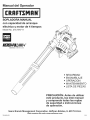
HANDHELD BLOWER
Model No. 316.794711
INCREDI.PULLX H
UNBELIEVABLE
STARTING
E A S E
• SAFETY
ASSEMBLY
OPERATION
MAINTENANCE
PARTS LIST
ESPANOL, R 11
CAUTION: Before using this
product, read this manual and
understand all safety rules and
operating instructions.
Sears Brands
Management
Corporation,
Visit our website:
769-06493A
PO0
Hoffman
Estates, IL 60179 U.S.A.
www.craftsman.com
09/11
TABLE OF CONTENTS
Rules for Safe Operation .................................................................................
2
Warranty ..........................................................................................................
Know Your Unit ...............................................................................................
4
4
Assembly Instructions .....................................................................................
Oil and Fuel Information ..................................................................................
4
5
Starting/Stopping
Instructions ........................................................................
5
Operating Instructions ....................................................................................
6
Maintenance and Repair Instructions .............................................................
6
Cleaning and Storage .....................................................................................
8
Speed Start TM Accessory ................................................................................
8
Troubleshooting Chart .....................................................................................
9
Specifications ...............................................................................................
10
Parts List .......................................................................................................
22
Service Numbers ...........................................................................
Back Cover
The purpose of safety symbols is to attract your attention to possible dangers.
The safety symbols, and their explanations, deserve your careful attention
and understanding. The safety warnings do not by themselves eliminate any
danger. The instructions or warnings they give are not substitutes for proper
acc dent prevent on measures.
SYMBOL
SAFETYis ALERT:
danger,
warning
or caution.
Attention
required in Indicates
order to avoid
serious
personal
injury.
May be used in conjunction with other symbols or pictographs.
NOTE: Advises of information or instructions
maintenance of the equipment.
WARNING:
to yourself and
Failure to
obey a
safetythewarning
can result in to
injury
others.
Always
follow
safety precautions
reduce the risk of fire, electric shock and personal injury.
SPARK ARRESTOR NOTE
_lb
• IMPORTANT
CALIFORNIA
A
PROPOSITION
SAFETY INSTRUCTIONS
SAFETY WARNINGS
65
Engine exhaust, some of its constituents and
certain finished components contain or emit chemicals known to
the State of California to cause cancer and birth defects or other
reproductive harm. Wash hands after handling.
BEFORE OPERATING
WARNING:
unit, all safety
must be
followed. PleaseWhen
read using
these the
instructions
beforerules
operating
the unit
in order to ensure the safety of the operator and any bystanders.
Please keep these instructions for later use.
•
Read the instructions carefully. Be familiar with the controls and proper use
of the unit.
•
Do not operate this unit when tired, ill, or under the influence of alcohol,
drugs, or medication.
•
Children and teens under the age of 15 must not use the unit, except for
teens guided by an adult.
All guards and safety attachments must be installed properly before
operating the unit.
Inspect the unit before use. Replace damaged parts. Check for fuel leaks.
Make sure all fasteners are in place and secure. Replace parts that are
cracked, chipped, or damaged in any way. Do not operate the unit with
loose or damaged parts.
Carefully inspect the area before starting the unit. Remove all debris and
hard or sharp objects such as glass, wire, etc.
Clear the area of children, bystanders, and pets. At a minimum, keep all
children, bystanders, and pets outside a 50 feet (15 m) radius; there still
may be a risk to bystanders from thrown objects. Bystanders should be
encouraged to wear eye protection. If you are approached, stop the unit
immediately.
•
•
•
•
•
Squeeze the throttle control and check that it returns automatically
idle position. Make all adjustments or repairs before using unit.
CAUTION:
Failure
to obey injury
a safety
warning or
may
property damage
or personal
to yourself
to result
others.in
Always follow the safety precautions to reduce the risk of fire,
electric shock and personal injury.
Read the Operator's Manual and follow all warnings and safety
instructions. Failure to do so can result in serious injury to the operator
and/or bystanders. FOR QUESTIONS, CALL 1=800=4=MY=HOME®
WARNING:
READ ALL INSTRUCTIONS
vital to the operation or
DANGER:
Failure
obey aAlways
safety follow
warningthewill
resultprecautions
in serious
injury
to yourself
or totoothers.
safety
to reduce the risk of fire, electric shock and personal injury.
All information, illustrations, and specifications in this manual are based on the
latest product information available at the time of printing. We reserve the right
to make changes at any time without notice.
NOTE: For users on U.S. Forest Land and in the states of California, Maine,
Oregon and Washington.
All U.S. Forest Land and the state of California
(Public Resources Codes 4442 and 4443), Oregon and Washington require, by
law that certain internal combustion engines operated on forest brush and/or
grass-covered areas be equipped with a spark arrestor, maintained in effective
working order, or the engine be constructed, equipped and maintained for the
prevention of fire. Check with your state or local authorities for regulations
pertaining to these requirements. Failure to follow these requirements could
subject you to liability or a fine. This unit is factory equipped with a spark
arrestor. If it requires replacement, ask your LOCAL SERVICE DEALER to
install the Accessory Part #753=05900 Muffler Assembly
MEANING
to the
FOR GAS UNITS
WARNING:
Gasoline
is
explode if ignited.
Take the
highly
flammable
and its vapors can
following
precautions:
•
Store fuel only in containers specifically designed and approved for the
storage of such materials.
•
Always stop the engine and allow it to cool before filling the tank. Never
remove the fuel tank cap or add fuel when the engine is hot. Always loosen
the fuel tank cap slowly to relieve any pressure in the tank before fueling.
DO NOT smoke.
•
Always add fuel in a clean, well-ventilated
sparks or flames. DO NOT smoke.
•
Never operate the unit without the fuel cap securely in place.
•
Avoid creating a source of ignition for spilled fuel. Wipe up any spilled fuel
from the unit immediately, before starting the unit. Move the unit at least 30
ft. (9.1 m) from the fueling source and site before starting the engine. DO
NOT smoke.
outdoor area where there are no
Never start or run the unit inside a closed room or building. Breathing exhaust
fumes can kill. Operate this unit only in a well ventilated outdoor area.
WHILE OPERATING
•
Wear safety glasses or goggles that are marked as meeting ANSI Z87.11989 standards and are marked as such.
•
Never run the unit without the proper equipment attached.
the unit without the blower tubes attached.
•
To reduce the risk of hearing loss associated with sound level(s), always
wear ear/hearing protection when operating this unit.
•
Wear heavy long pants, boots, gloves, and a long sleeve shirt. Do not wear
loose clothing, jewelry, short pants, sandals or go barefoot. Secure hair
above shoulder level.
•
•
Use the unit only in daylight or good artificial light.
Keep outside surfaces free from oil and fuel.
•
Avoid accidental starting. Be in the starting position whenever pulling
the starter rope. The operator and unit must be in a stable position while
starting. Refer to Starting/Stopping Instructions.
•
Do not set unit on any surface except a clean, hard area while engine is
running. Debris such as gravel, sand, dust, grass, etc. could be picked up
by the air intake and thrown out by the discharge opening, damaging unit,
property, or causing serious injury to bystanders or operator.
Do not operate
OTHER SAFETY WARNINGS
Use
therighttool.Onlyusethistoolforitsintended
purpose.
Donotforce
unit.Itwilldothejobbetter
andwithlesslikelihood
ofinjury
Never store the unit, with fuel in the tank, inside a building where fumes
atarateforwhich
itwasdesigned.
may reach an open flame (pilot lights, etc.) or sparks (switches, electrical
motors, etc.).
Donotoverreach
orusefromunstable
surfaces
such
asladders,
trees,
steep
slopes,
rooftops,
etc.Always
keep
proper
footing
andbalance.
Allow the engine to cool before storing or transporting. Be sure to secure
the unit while transporting.
Always
holdtheunitwithafirmgripwhen
operating.
Store the unit in a dry place, either locked up or up high to prevent
Keep
hands,
face,
and
feetaway
from
allmoving
parts.
Donottouch
ortryto
unauthorized use or damage. Keep out of the reach of children.
stoptheimpeller
when
itisrotating.
Donotoperate
without
guards
inplace.
douse or squirt the unit with water or any other liquid. Keep handles
Donotputanyobject
intoopenings.
Donotusewithanyopening
blocked; Never
dry, clean, and free from debris. Clean after each use, see Cleaning and
keep
freeofdirt,debris,
andanything
thatmayreduce
theairflow.
Storage instructions.
Donottouch
theengine
ormuffler.
These
parts
getextremely
hotfrom
Keep these instructions. Refer to them often and use them to instruct other
operation,
even
after
theunitisturned
off.
users. If you loan this unit to others, also loan these instructions to them.
Donotoperate
theengine
faster
than
thespeed
needed
todothejob.Do SPECIAL
NOTE: Exposure to vibrations through prolonged use of gasoline
notruntheengine
athigh
speed
when
notinuse.
powered hand tools could cause blood vessel or nerve damage in the
Always
stoptheengine
when
operation
isdelayed
orwhen
walking
from
fingers, hands, and joints of people prone to circulation disorders or
onelocation
toanother.
abnormal swelling. Prolonged use in cold weather has been linked to blood
Stoptheengine
formaintenance,
repair,
toinstall
orremove
theblower
vessel damage in otherwise healthy people. If symptoms occur such as
tubes.
Theunitmust
bestopped
andtheimpeller
nolonger
turning
to
numbness, pain, loss of strength, change in skin color or texture, or loss of
avoid
contact
withtherotating
blades.
feeling in the fingers, hands or joints, discontinue use of this tool and seek
Ifyoustrike
orcome
intocontact
withaforeign
object,
stoptheengine
medical attention. An anti-vibration system does not guarantee avoidance
immediately
andcheck
fordamage.
Donotoperate
before
repairing
of these problems. Users who operate power tools on a regular basis must
closely monitor their physical condition and the condition of this tool.
damage.
Donotoperate
theunitwithloose
ordamaged
parts.
Use
onlygenuine
factory
replacement
parts
andaccessories
forthis
unit.These
areavailable
fromyourauthorized
service
dealer.
Use
ofany
unauthorized
parts
oraccessories
could
leadtoserious
injury
totheuser
ordamage
totheunit,
andvoid
yourwarranty.
SAVE THESE INSTRUCTIONS
Toreduce
firehazard,
replace
faulty
muffler
andspark
arrestor.
Keep
the
engine
andmuffler
freefromgrass,
leaves,
excessive
grease
orcarbon
buildup.
Never
usethisunitforspreading
chemicals,
fertilizers
orother
substances
which
maycontain
toxicmaterials.
Never
point
theblower
inthedirection
ofbystanders,
animals,
windows
or
automobiles.
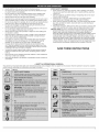
• SAFETY
& iNTERNATiONAL
This operator's manual describes safety and international symbols and pictographs
safety, assembly, operating and maintenance and repair information.
SYMBOL
MEANING
SYMBOLS
•
that may appear on this product.
SYMBOL
MEANING
Read the operator's
manual for complete
CRAFTSMAN
2 YEAR
FULL
WARRANTY
FOR 2 YEARS from the date of purchase, this product is warranted against any defects in material or workmanship.
or replacement if repair is unavailable.
For warranty
coverage
This warranty
details to obtain free repair or replacement,
covers ONLY defects
in material
and workmanship.
A defective product will receive free repair
visit the web site: www.craftsman.com
Warranty
coverage
does NOT include:
•
•
Expendable items that can wear out from normal use within the warranty period, such as air cleaner or spark plug.
Product damage resulting from user attempts at product modification or repair or caused by product accessories.
•
Repairs necessary because of accident or failure to operate or maintain the product according to all supplied instructions.
•
Preventive maintenance, or repairs necessary due to improper fuel mixture, contaminated or stale fuel.
This warranty is void if this product is ever used while providing commercial services or if rented to another person. This warranty gives you specific legal
rights, and you may also have other rights which vary from state to state.
Sears Brands Management Corporation, Hoffman Estates, IL 60179
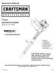
APPLICATIONS
*
G ip
Cleaning yards, garages, driveways, porches, patios,
around walls, fences and more
on/off
Switch
Trigger
Spark
Cruise
Plug Cover
Control
TOOLS REQUIRED:
*
Flathead Screwdriver
Upper
Blower
Tube
Primer Bulb
Oil Plug
_,
Starter
(Straight)
Lower Blower
Air Filter Cover
Rope Grip
\\/
Tube
(Curved)
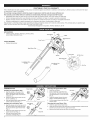
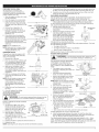
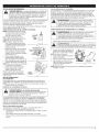
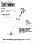
ASSEMBLING
UNiT
Removing
Instafling the Upper Blower Tube
1.
Align the bump on the end of the
upper blower tube with the bump
slot on the bottom end of the blower
outlet (Fig. 1).
2.
Insert the upper blower tube into the
blower outlet (Fig. 1).
3.
Twist the upper blower tube clockwise
until it locks into place (Fig. 1).
Instafling the Lower Blower
1.
2.
3.
4
Tube
Align the bump slot on the top end of
the lower blower tube with the bump
on the end of the upper blower tube
(Fig. 2).
Place the lower blower tube onto the
upper blower tube (Fig. 2).
Twist the lower blower tube
clockwise until tight (Fig. 2).
Blower
Outlet
_4_
1.
2.
3.
4.
Fig. 1
Pull the upper blower tube from the
blower outlet.
Removing
Upper Blower
Tube
1.
2.
Lower
Blower
Tube
Bump
\
Bump Slot
Fig. 2
3.
the Upper Blower Tube
Hold the unit firmly.
Insert a flathead screwdriver into
the tube lock. Twist the screwdriver
counterclockwise
1/4 turn and hold
(Fig. 3).
Grasp the upper blower tube and
twist it counterclockwise
(Fig. 3).
the Lower Blower
Fig,3
Tube
Hold the upper blower tube firmly.
Grasp the lower blower tube and twist it counterclockwise
until the lower
blower tube unlocks from the upper blower tube.
Remove the lower blower tube from the upper blower tube.
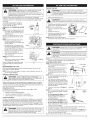
RECOMMENDED
OiL TYPE
FUELING THE UNIT
WARNING:
OVERFILLING
CRANKCASE
MAYthe
CAUSE
SERIOUS PERSONAL
INJURY.OIL
Check
and maintain
proper oil level in the crankcase; it is important and cannot be
overemphasized. Check the oil before each use and change it as
needed. See Changing the Oil.
Using the proper type and weight of oil in the crankcase is extremely
important. Check the oil before each use and change the oil regularly. Failure
to use the correct oil, or using dirty oil, can cause premature engine wear
and failure.
Use a high-quality SAE 30 weight oil
of API (American Petroleum Institute)
service class SF, SG, SH.
ADDING OIL TO CRANKCASE:
USE
3.
WARNING:
Remove
slowlythetofuel
avoid
from infuel
spray. Never operate
the fuel
unitcap
without
capinjury
securely
place.
Wipe up any gasoline that may have
spilled.
4.
Reinstall the fuel cap.
I
ell
Fig.7
Plu_
Wipe up any oil that may have spilled
and reinstall the oil fill plug.
Check oil before each use and change
as needed. Refer to Checking the Oil
Level.
WARNING:
Operate this unit only in a well-ventilated outdoor
area. Carbon monoxide exhaust fumes can be lethal in a
confined area.
Fig. 5
WARNING:
Avoid accidental starting. Make sure to be in the
starting position when pulling the starter rope (Fig. 10). To avoid
serious injury, the operator and unit must be in a stable position
while starting.
Hole
Fig. 6
Old fuel is the primary reason for poor unit performance.
fresh, clean, unleaded gasoline.
Be sure to use
NOTE: This is a four cycle engine. In order to avoid damage to the unit, do
not mix oil with gasoline.
Fuels
been proven that fuel containing greater than 10% ethanol will
WARNING:
DO engine
NOT USE
IN THIS UNIT. It has
likely damage this
and E85
void FUEL
the warranty.
Today's fuels are often a blend of gasoline and oxygenates such as ethanol,
methanol or MTBE (ether). Alcohol-blended
fuel absorbs water. As little as
1% water in the fuel can form acids when stored. Use fresh fuel (less than 30
days old), when using alcohol-blended
fuel.
Using Blended Fuels
If choosing to use a blended fuel, or its use is unavoidable,
recommended precautions:
NOTE: This unit has the Incredi-Pull TM starting system, which significantly
reduces the effort required to pull the starter rope.
STARTING INSTRUCTIONS
NOTE: When starting the unit, make sure
it is not directed at bystanders or
loose debris.
FUEL TYPE
of Blended
FuelTank
Move the unit at least 30 ft. (9.1 m)
from the fueling source and site
before starting the engine.
NOTE: Dispose of any old gasoline in
accordance with federal, state and local regulations.
Fig. 4
4.
Definition
Place the gas container's spout into
the fill hole on the fuel tank and fill.
3.
oil fill hole (Fig. 6).
NOTE: Never add oil to the fuel or fuel
tank.
RECOMMENDED
Remove the fuel cap (Fig. 7).
5.
NOTE: Save the empty oil bottle. It can
be used to measure the correct
amount during future oil changes. See
Changing the Oil.
2.
1.
NOTE: Do not overfill the tank.
INITIAL
Unscrew the top of the bottle of oil
and remove the paper seal covering
the opening. Replace the top and cut
the tip off the funnel spout (Fig. 4).
With the unit on a flat level surface,
remove the oil plug (Fig. 5).
Pour the entire bottle of oil into the
Add up
fuelany
in spilled
a clean, fuel
levelimmediately.
and well ventilated
Wipe
Avoid creating
a source of ignition for spilled fuel. Do not start the engine until
fuel vapors dissipate.
2.
NOTE: This unit is shipped without oil in
the engine. To avoid damage to the
unit, put oil in the crankcase prior to
starting the unit.
This unit is supplied with one 2.03 fl.oz.
(60 ml) bottle of SAE 30 SF, SG, SH oil
(Fig. 4).
1.
WARNING:
outdoor area.
follow
Always use fresh unleaded gasoline
Use the fuel additive STA-BIL® or an equivalent
Drain tank and run the engine dry before storing unit
Using Fuel Additives
The use of fuel additives, such as STA-BIL® Gas Stabilizer or an equivalent,
will inhibit corrosion and minimize the formation of gum deposits. Using a
fuel additive can keep fuel from forming harmful deposits in the carburetor
for up to six (6) months. Add 0.8 oz. (23 ml) of fuel additive per gallon of fuel
according to the instructions on the fuel additive container. NEVER add fuel
additives directly to the unit's gas tank.
1.
2.
Switch
1
Cruise
Control
Trigger
Check the oil level in the crankcase.
Refer to Checking the Oil Level.
Fill the fuel tank with fresh, clean
unleaded gasoline. Refer to Fueling
the Unit.
NOTE: There is no need to turn the unit
on. The On/Off Switch is in the ON ( I )
position at all times.
Fully press and release the primer
bulb 10 times, slowly. Some amount
of fuel should be visible in the primer
bulb (Fig. 9). If fuel cannot be seen in
the bulb, press and release the bulb
until fuel is visible.
4. Move the choke lever to Position 1
(Fig. 9).
NOTE: The unit should be started in idle.
Do not squeeze the trigger until step
8 (Fig. 8).
5. Do not squeeze the trigger. Crouch
in the starting position (Fig. 10).
Pull the starter rope 5 times in a
controlled motion.
Fig. 8
3.
6.
7.
Do not squeeze the trigger. Move
the choke lever to Position 2 (Fig. 9).
Do not squeeze the trigger. Pull the
starter rope 3-5 times in a controlled
motion to start the engine.
Primer
Bulb
Fig. 9
_I[
Sta ,lii_gn
Fig. 10
8.
Squeeze and hold the trigger, or press down the cruise control (Fig. 8),
and allow the engine to warm up for 30 to 60 seconds.
9.
Continue to squeeze the trigger. Move the choke lever to Position 3 (Fig.
9) and continue warming the engine for an additional 60 seconds. The
unit may be used during this time.
WARNING:
Gasoline is extremely flammable. Ignited vapors
may explode. Always stop the engine and allow it to cool before
filling the fuel tank. Do not smoke while filling the tank. Keep
sparks and open flames at a distance from the area.
On/Off
IE.. the engine does not start, go back to step 3.
IF,..theengine
failstostartafter
afewattempts,
move
thechoke
lever
to
Position
3andpullthestarter
rope
3-8timesinacontrolled
motion.
The
engine
should
start.Ifnot,repeat.
IFWARM...
Iftheengine
isalready
warm,
goback
tostep6.
HOLDING
STOPPING INSTRUCTIONS
•
The unit is in the right hand and on
the right side of the body. Do not
block the air intake which will affect
the unit's performance (Fig. 11).
•
If the conditions are dusty, the
operator is wearing a dust mask or
face mask
1.
Release your hand from the trigger. Allow the engine to cool down by idling.
2.
Press and hold the On/Off switch in the OFF (O) position until the unit
comes to a complete stop (Fig. 8).
•
•
NOTE: This unit can use a Speed Start TM Accessory!
STARTING INSTRUCTIONS
NOTE: When starting the unit, make sure it is not directed
loose debris.
at bystanders or
1.
Check the oil level in the crankcase.
2.
Fill the fuel tank with fresh, clean unleaded gasoline. Refer to Fueling the
Unit.
4.
Fully press and release the primer bulb 10 times, slowly. Some amount of
fuel should be visible in the primer bulb (Fig. 9). If fuel cannot be seen in
the bulb, press and release the bulb until fuel is visible.
Move the choke lever to Position 1 (Fig. 9).
NOTE: The unit should be started in idle. Do not squeeze the trigger until
step 8 (Fig. 8).
5. Crouch in the starting position (Fig. 10). Insert the Speed Start TM
accessory into the Speed Start TM port on the side of the unit (Fig. 25).
Refer to the Operation section of the Speed Start TM accessory operator's
manual.
6.
Do not squeeze
seconds.
the trigger.
Run the Speed Start
7.
Do not squeeze
the trigger,
Move the choke lever to Position
8.
Do not squeeze the trigger, Run the Speed Start TM accessory in
intervals no longer than 2 seconds each until the unit starts.
9.
Remove the Speed Start
TM
TM
accessory for 2
2 (Fig. 9).
accessory from the unit.
TIPS
Using the Variable Speed Cruise Control
For longer periods of operation and to
eliminate possible finger fatigue.
1.
Refer to Checking the Oil Level.
NOTE: There is no need to turn the unit on. The On/Oft Switch is in the ON ( I )
position at all times.
Fig. 11
The unit is in good working condition
The tubes are in place and secure
OPERATING
Please refer to the Speed Start TM accessory operator's manual for proper
use of this feature. (Items Sold Separately! Refer to page 8 of this manual
for more information about these Speed Start TM accessories.)
3.
THE BLOWER
Before operating the unit, stand in the
operating position and check for the
following:
2.
Move the variable speed cruise
control toward the FAST position to
incrementally increase or maintain
the unit's engine speed (Fig. 12).
When the variable speed cruise
control is pressed, the trigger will
recede into the handle.
Cruise
Cont_
To decrease engine speed, move the
Fig, 12
variable speed cruise control to the
SLOW position and the trigger will return to idle (Fig. 12).
Other Tips
•
Always use a firm grip when holding the unit.
•
•
To reduce the risk of hearing loss, hearing protection is required.
Operate power equipment only at reasonable hours when people might
not be disturbed. Comply with times listed in local ordinances. Usual
recommendations are 9:00 am to 5:00 pm, Monday through Saturday.
•
To reduce noise levels, operate the unit at the lowest possible speed to
do the job.
•
Use rakes and brooms to loosen debris before blowing.
•
•
Watch for bystanders, open windows or cars; blow debris safely away.
Use the curved tube extension so the unit can work closer to the ground.
•
Clean up after using blowers and other equipment.
appropriately.
Dispose of debris
10. Squeeze and hold the trigger, or press down the cruise control (Fig. 8),
and allow the engine to warm up for 30 to 60 seconds.
11. Continue to squeeze the trigger. Move the choke lever to Position 3 (Fig. 9)
and continue warming the engine for an additional 60 seconds. The unit may
be used during this time.
IF,..the engine does not start, go back to step 3.
IF,..the engine fails to start after a few attempts, move the choke lever to
Position 3 and squeeze the throttle control. Run the Speed Start TM
accessory in intervals no longer than 2 seconds each until the unit starts.
IF WARM... If the engine is already warm, go back to step 7.
STOPPING INSTRUCTIONS
1.
Release your hand from the trigger. Allow the engine to cool down by idling.
2.
Press and hold the On/Off switch in the OFF (O) position until the unit
comes to a complete stop (Fig. 8).
MAINTENANCE
SCHEDULE
Perform these required maintenance procedures at the frequency stated in
the table. These procedures should also be a part of any seasonal tune-up.
NOTE: Some maintenance procedures may require special tools or skills. If
unsure about these procedures take the unit to Sears or other qualified
service dealer. Call 1-800-4-MY-HOME®
for more information.
NOTE: Maintenance, replacement, or repair of the emission control devices
and system may be performed by a Sears or other qualified service dealer.
Call 1-800-4=MY=HOME® for more information.
NOTE: Please read the California/EPA statement that came with the unit for a
complete listing of terms and coverage for the emissions control devices,
such as the spark arrestor, muffler, carburetor, etc.
FREQUENCY
MAINTENANCE
Every 10 hours
Clean and oil air filter
REQUIRED
SEE
p. 7
After 1st 10
hours
Change oil
Check rocker arm to valve clearance and adjust
p. 7
p. 7
Every 40 hours
Change oil
Check rocker arm to valve clearance and adjust
p. 7
p. 7
Check spark plug condition and gap
p. 8
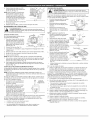
CHECKING
THE OiL
LEVEL
The importance of checking and
maintaining the proper oil level in the
crankcase cannot be overemphasized.
Check oil before each use:
1.
2.
3.
4.
5.
6.
If, after checking the fuel and cleaning the air filter, the engine still will not
idle, adjust the idle speed screw as follows:
o,O-R,n0
,o0
1.
2.
If the oil level is not touching the
innermost thread on the oil fill hole,
add a small amount of oil to the oil
fill hole and recheck (Fig. 13). Repeat
this procedure until the oil level
reaches the innermost thread on the
oil fill hole.
Fig. 14
•
•
Release the trigger and let the engine
idle. If the engine stops, insert a
small Phillips screwdriver in between
the Air Filter Cover and the Engine
Cover (Fig. 19). Turn the idle speed
screw 1/8 of a turn clockwise at a
time until the engine idles smoothly.
the engine will not idle
the engine hesitates or stalls on acceleration
WARNING:
To itavoid
serious
always turnit. the
unit off and allow
to cool
beforepersonal
cleaninginjury,
or maintaining
Fill Level
This adjustment requires disassembly
of the engine. If you feel unsure or
unqualified to perform this, take the
unit to a Sears or other qualified service
dealer.
__
4-cceMo_o,o_
The engine must be cold when
checking or adjusting the rocker arm
clearance.
Fig. 16
1.
Cleaning
4.
T-Fig. 17
the Air Filter
WARNING:
Toitavoid
serious
unit off and allow
to cool
beforepersonal
cleaning injury,always
or maintainingturnit. the
5.
Failure to maintain the air filter will VOID
the warranty.
1.
2.
3.
To open the air filter cover, push
the tab on the left side of the cover
inward and pull the air filter cover
slightly out and to the right (Fig. 18).
Remove the air filter (Fig. 18).
Wash the filter in detergent and
water. Making sure to rinse the filter
thoroughly and allow it to dry.
•
Fig. 20
Remove the 8 engine cover screws
with the appropriate tool (Fig. 20),
then remove the cover.
AIR FILTER MAINTENANCE
Once full, replace the oil plug.
screws
This task should be performed
inside, in a clean, dust free area.
NOTE: Make sure to store the screws so
that they can be reinstalled into their
original holes.
2. Disconnect the spark plug wire.
3. Clean dirt from around the spark
plug and rocker arm cover.
Remove the spark plug from the
cylinder by turning a 5/8 in. socket
counterclockwise.
6.
If not and
ROCKER ARM CLEARANCE
NOTE: Use the bottle and spout saved
from initial use to measure the
correct amount of oil. The fill line
on the bottle's label measures
approximately 2.03 ounces (60 ml)
(Fig. 16).
Check the level, See Checking the
Oil Level.
Fig. 19
Fig. 15
Wipe up any oil residue on the
unit and clean up any oil that may
have spilled. Dispose of the oil
according to federal, state and local
regulations.
Refill the crankcase with 2.03 fluid
ounce (60 ml) of SAE 30 SF, SG, SH
oil (Fig. 17).
5.
ldle AsdJrUeStwm
e nt
•
there is a loss of engine power
take the unit to a Sears or other qualified service dealer.
Change the oil while the engine is still
warm. The oil will flow freely and carry
away more impurities.
4.
Start the engine and warm up
according to the Starting/Stopping
Instructions.
Checking the fuel, cleaning the air filter,
and adjusting the idle speed should solve most engine problems.
all of the following are true:
NOTE: Make sure the O-ring is in place
on the oil plug when checking and
changing the oil (Fig. 14).
CHANGING THE OIL
3.
Swing the cover to the left and press closed so the air filter cover tab
snaps into the slot on the back plate (Fig. 18).
NOTE: Careless adjustments can seriously damage to the unit. A Sears or
other qualified service dealer should make carburetor adjustments.
Fig. 13
Look into the oil fill hole (use a
flashlight if needed). The oil should
be just touching the innermost
thread (Fig. 13).
Remove the oil fill plug.
Pour the oil out of the oil fill hole and
into a container by tipping the unit
to a vertical position (Fig. 15). Allow
ample time for complete drainage.
8.
The idle speed of the engine is adjustable. An idle adjustment screw is
between the air filter cover and the engine starter housing (Fig. 19).
()il Fill Line-
NOTE: Do not overfill the unit.
1.
2.
To reinstall the air filter cover, position the hooks on the right side of the
air filter cover into the slots at the right side of the back plate (Fig. 18).
IDLE SPEED ADJUSTMENT
Stop the engine and allow oil to drain
into the crankcase.
Place the engine on a level surface.
Clean the area around the oil plug
before removing it. Keep dirt, grass
clippings, and other debris out of the
engine.
Remove the oil plug (Fig. 14).
7.
Rocker
Arm
cover
Spark
plug,
Nole
Remove the screw holding the rocker
arm cover with the appropriate tool
(Fig. 21). Remove the rocker arm
_
cover and gasket.
Turn the flywheel slowly to bring the
piston to the top of its travel (known
as top dead center). Check that:
_
The piston is at the top of its travel
by looking in the spark plug hole
(Fig. 21)
Screw
Fig. 21
Adjustment
Nut
0.003-0.006
in.
(0.076-0.152
mm)
Feeler Gauge
RockerArm
Valve
Stem
Fig. 22
•
Both rocker arms move freely, and both valves are closed.
If these statements are not true, repeat this step.
Tab
Air Filter
4.
Lightly coat the filter with clean SAE
30 motor oil.
5.
Squeeze the filter to spread and remove excess oil.
Air Filtl
Fig, 18
6. Replace the filter.
NOTE: Operating the unit without the air filter will VOID the warranty.
" Cover
6.
Slide the feeler gauge between the rocker arm and the valve return
spring. Measure the clearance between the valve stem and rocker arm
(Fig. 22). Measure both the intake and exhaust valves.
The recommended clearance for both intake and exhaust is .003 - .006 in.
(.076 - 0.152 mm). Use a standard automotive .005 in. (0.127 mm) feeler
gauge. The feeler gauge should slide between the rocker arm and valve stem
with a slight amount of resistance, without binding (Fig. 22).
7. Iftheclearance
isnotwithin
specification:
a. Turn
theadjusting
nutusing
a5/16
inch
(8mm)
wrench
ornutdriver
(Fig.
22).
• Toincrease
clearance,
turntheadjusting
nutcounterclockwise.
• Todecrease
clearance,
turntheadjusting
nutclockwise.
b. Recheck
bothclearances,
andadjust
asnecessary.
8. Reinstall
therocker
armcover
using
anewgasket
(Fig.
21).Torque
the
screw
to:20-30
in.lb(2.2-3.4
N.m).
9. Check
thespark
plugandreinstall.
SeeReplacing the Spark Plug.
10. Reinstall the spark plug wire.
11. Reinstall the engine cover. Check alignment of the cover before
tightening the screws. Tighten screws.
NOTE: Make sure that the screws are reinstalled into their original holes (Fig.
20).
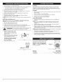
REPLACING THE SPARK PLUG
Use a replacement part number 753-05784 or Champion®
#RDZ4H. The correct spark gap is 0.025 in. (0.635 mm).
1. Stop the engine and allow it to cool.
Open the spark plug cover (Fig. 23).
3.
4.
Grasp the plug wire firmly and pull the cap from the spark plug.
Clean dirt from around the spark plug. Remove the spark plug from the
cylinder head by turning a 5/8 in. socket counterclockwise.
WARNING:Grit Do
not engine
sand blast,
cleancylinder.
spark plug
electrodes.
in the
could scrape
damageor the
6.
Use a small brush to clean off the outside of the unit. Do not use strong
detergents. Household cleaners that contain aromatic oils such as pine
and lemon, and solvents such as kerosene, can damage plastic housing or
handle. Wipe off any moisture with a soft cloth.
STORAGE
*
.
Never store the unit with fuel in the tank where fumes may reach an open
flame or spark.
Allow the engine to cool before storing.
.
.
.
Lock up the unit to prevent unauthorized use or damage.
Store the unit in a dry, well-ventilated area.
Store the unit out of the reach of children.
LONG TERM STORAGE
1.
spark plug
2.
5.
CLEANING
Replace cracked, fouled or dirty
spark plug. Set the spark gap at
0.025 in. (0.635 mm) using a feeler
gauge (Fig. 24).
Install a correctly-gapped
spark plug
in the cylinder head. Turn the 5/8 in.
socket clockwise until snug.
Remove the fuel cap, tip the unit and drain the fuel into an approved
container.
NOTE: Do not use gasoline that has been stored for more than 30 days.
Dispose of old gasoline in accordance with federal, state and local
regulations.
2. Start the engine and allow it to run until it stalls. This ensures that all
gasoline has been drained from the carburetor.
3.
Allow the engine to cool. Remove the spark plug and put 5 drops of high
quality motor oil into the cylinder. Pull the starter rope slowly to distribute
the oil. Reinstall the spark plug.
NOTE: Remove the spark plug and drain all of the oil from the cylinder before
attempting to start the blower after storage.
4. Change the oil, referring to Changing the Oil. Dispose of the old oil in
accordance with federal, state and local regulations.
5. Thoroughly clean the unit and inspect for any loose or damaged parts.
Repair or replace damaged parts and tighten loose screws, nuts or bolts.
The unit is ready for storage.
If using a torque wrench, torque to:
110-120 in.*ib. (12.3=13.5 N,m)
Do not overtighten.
7.
Fig. 23
This unit can be started with an optional
Speed Start TM accessory (items sold
separately). Please contact your local
Craftsman retailer, call 1-800-4-MYHOME ® or visit www.craftsman.com
for more information.
Reinstall the spark plug cover.
Speed Start
Port
TM
(O "t3255in
r nm}_
Fig. 25'
Fig. 24
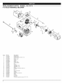
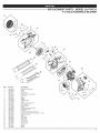
item No.
Description
316.85951
..............................
316.85952
.................................
Plug-in
Power
Power
Start
Bit Start
PROBLEM
SOLUTION
Primer bulb wasn't pressed enough
Slowly press primer bulb 10 times
Fouled spark plug
Replace or clean the spark plug
Improper idle speed
Adjust according to the Idle Speed Adjustments
Fouled spark plug
Replace or clean the spark plug
HELP?
o Find this and a[[ your other product manuats ontine.
o Get answers from our team of home experts.
_ Get a personalized maintenance plan for your home.
o Find information and rods to hdp with home projects.
section.
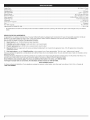
Engine Type ..........................................................................................................................................................................................................
Air-Cooled, 4-Cycle
Displacement ..............................................................................................................................................................................................................................
25 cc
Operating RPM .....................................................................................................................................................................................................................
7,000 rpm
Idle Speed RPM ......................................................................................................................................................................................................
3,600 - 4,600 rpm
Blower Velocity ............................................................................................................................................................................................
up to 150 mph (240 kmh)
Blower Air Output .......................................................................................................................................................................................
up to 450 cfm (12.7 cmm)
Valve clearance ..............................................................................................................................................................................
0.003-0.006 in. (0.076-0.152 mm)
Spark Plug Gap ................................................................................................................................................................................................
0.025 inch (0.635 mm)
Lubrication ..........................................................................................................................................................................................................................
SAE 30 Oil
Crankcase Oil Capacity ...............................................................................................................................................................................................
Fuel .......................................................................................................................................................................................................................................
2.03 oz (60 ml)
Unleaded
Fuel Tank Capacity ........................................................................................................................................................................................................
Approximate Unit Weight (No fuel) ..................................................................................................................................................................................
14 oz (414 ml)
11 Ibs. (5 kg)
*
All specifications
notice.
are based on the latest product information
REPAIR PROTECTION
available at the time of printing. We reserve the right to make changes at any time without
AGREEMENTS
Congratulations on making a smart purchase. Your new Craftsman@ product is designed and manufactured for years of dependable operation. But like all
products, it may require repair from time to time. That's when having a Repair Protection Agreement can save you money and aggravation.
Here is what the Repair Protection
Plan Agreement
by our 10,000 professional
includes:
[_
Expert service
[_
Llnlimited
[_
Product
[_
Discount of 10% from regular price of service and related installed parts not covered
maintenance checks
service
and no charge
replacement
repair specialists
for parts and labor on all covered repairs
up to $1500 if your covered product cannot be fixed
by the agreement; also, 10% off regular price of preventive
[_
Fast help by phone - we call it Rapid Resolution - phone support from a Sears representative. Think of us as a "talking owner's manual."
Once you purchase the Agreement, a simple phone call is all that it takes for you to schedule service. You can call anytime day or night, or schedule a service
appointment online.
The Repair Protection Agreement is a risk-free purchase. If you cancel for any reason during the product warranty period, we will provide a full refund. Or a
prorated refund anytime after the product warranty period expires. Purchase you Repair Protection Agreement today!
Some limitations and exclusions apply. For prices and additional
*Coverage
in Canada varies on some items. For fuU details
information
in the U.S.A. call 1=800=827=6655.
call Sears Canada at 1 =800=361 =6665.
Sears Installation
For Sears professional
1=800=4=MY=HOME®.
10
installation of home appliances,
Service
garage door openers, water heaters, and other major home items, in the U.S.A. or Canada call
Manual del Operador
CRnJ:rSMRH
SOPLADORA
MANUAL
con capacidad
de arranque
el6ctrico y motor de 4 tiempos
Model No. 316.794711
INCREDI.PUL
L
UNBELIEVABLE
STARTING
E A S E
•
•
•
•
SEGURIDAD
ENSAMBLAJE
OPERACION
MANTENIMIENTO
LISTA DE PIEZAS
PRECAUCION: Antes de utilizar
este producto, lea este manual
y comprenda todas las reglas
de seguridad e instrucciones
de operaci6n.
Sears Brands
Management
Visite
769-06493A
P00
Corporation,
nuestro
sitio
web:
Hoffman
Estates, IL 60179 U.S.A.
www.craftsman.com
09/11
TABLA DE CONTENIDO
Normas para operarlo de manera segura .....................................................
Garantia ........................................................................................................
Conozca su unidad .......................................................................................
Instrucciones de ensamble ...........................................................................
12
14
14
14
Informaci6n del aceite y del combustible .....................................................
15
Instrucciones de arranque y apagado ..........................................................
16
Instrucciones de operaci6n ...........................................................................
17
Instrucciones de mantenimiento y reparaci6n ..............................................
17
Limpieza y almacenamiento .........................................................................
19
Accesorio Speed Start TM ..............................................................................
19
Tabla de Iocalizaci6n y soluci6n de problemas .............................................
20
Especificaciones ...........................................................................................
21
Lista de piezas ..............................................................................................
22
NOmeros de servicio .................................................................
Contraportada
El prop6sito de los simbolos de seguridad es Ilamar su atenci6n sobre
posibles peligros. Los simbolos de seguridad, y sus explicaciones, merecen I
toda su atenci6n y comprensi6n. Las advertencias de seguridad no eliminan
ningQn peligro pot si mismas. Las instrucciones o advertencias que ofrecen
no sust tuyen a as med das adecuadas de prevenc 6n de acc dentes.
SIMBOLO
ALERTA
SEGURIDAD:
peligro,
advertencia
o precauci6n.DE
Debe
prestar atenci6n Indica
para evitar
graves
lesiones
personales. Puede utilizarse junto a otros simbolos o pictografias.
NOTA: Indica informaci6n o instrucciones de vital importancia
operaci6n o el mantenimiento del equipo.
_:_
Toda la informaci6n, las ilustraciones y especificaciones
que contiene este
manual se basan en la informaci6n m&s reciente del producto, existente en
el momento de la impresi6n. Nos reservamos el derecho de hacer cambios
en cualquier momento sin previo aviso.
• INSTRUCCIONES
PROPOSICI()N
PELIGRO:
obedecer
de seguridad
puede conducir Elano
que
usted u una
otrasadvertencia
personas sufran
graves
lesiones. Siga siempre las precauciones de seguridad para reducir
el riesgo de incendio, descarga electrica o lesiones personales.
lesiones. Siga siempre las precauciones de seguridad para reducir
el riesgo de incendio, descarga electrica o lesiones personales.
PRECAUCION:
El no en
obedecer
una
advertencia
de usted
seguridad puede resultar
dafio a la
propiedad
o a que
u otras personas sufran lesiones personales. Siga siempre las
precauciones de seguridad para reducir el riesgo de incendio,
descarga electrica o lesiones personales.
Lea el Manual del Operador y siga todas las advertencias
e
instrucciones de seguridad. De no hacerlo, el operador y/o las personas
que Io rodean pudieran sufrir graves lesiones. Sl TIENE PREGUNTAS,
LLAME AL 1=800=4=MY=HOME®
DE SEGURIDAD
65 DEL ESTADO DE CALIFORNIA
para la
ADVERTENCIA:
El no
advertencia
seguridad puede resultar
en obedecer
que usted una
u otras
personasdesufran
NOT.& SOBRE EL PARACHISPAS
NOTA: Para usuarios de la Zona Forestal de EE. UU., y los estados de
California, Maine, Oreg6n y Washington.
Todas las Zonas Forestales de
los EE.UU. y el estado de California (C6digos de Recursos PQblicos 4442
y 4443), Oregon y Washington requieren, segQn la ley, que ciertos motores
de combusti6n interna que operen en el bosque y/o en zonas cubiertas de
hierba, se encuentren equipados con un parachispas, sean mantenidos en
buen estado de funcionamiento,
o que el motor sea construido, equipado
y mantenido, para prevenir incendios. Compruebe con sus autoridades
estatales o locales las regulaciones relacionadas con estos requisitos. Si no
cumple con estos requisitos podria estar sujeto a responsabilidad civil o a
una multa Esta unidad viene equipada de fabrica con un parachispas.
Si necesita reemplazarlo, pidale a su DISTRIBUIDOR DE SERVICIO LOCAL
instalarle la Pieza Accesorio #753=05900 del ensamblaje del silenciador.
SIGNIFICADO
IMPORTANTES
AVISOS DE SEGURIDAD
GASOLINA
PARA LAS UNIDADES
QUE TRABAJAN
CON
ADVERTENCIA:
Los gases de escape, algunos de sus
componentes y determinados productos terminados contienen
o emiten productos quimicos de los que el estado de California
tiene conocimiento provocan cancer, malformaciones cong_nitas
u otros daSos al sistema reproductor. Lavese las manos despu_s
de manipularlo.
LEA TODAS LAS INSTRUCCIONES
ANTES DE OPERAR LA UNIDAD
ADVERTENCIA:
es altamente
gases pueden explotar Lasigasolina
se encienden.
Tome
•
•
ADVERTENCIA:
Deben laseguirse
seguridad cuando se opera
unidad.
todas
las normas
de
Lea estas
instrucciones
antes de operar la unidad a fin de garantizar la seguridad del
operador y de cualquier otra persona presente. Guarde estas
instrucciones para poder usarlas m&s adelante.
•
•
•
Lea las instrucciones cuidadosamente.
uso adecuado de la unidad.
Familiaricese con los controles y el
•
•
No opere esta unidad siesta cansado, enfermo, o bajo los efectos del
alcohol, drogas o medicamentos.
Los nifios y los adolescentes menores de 15 afios de edad no deben usar la
unidad. Los adolescentes pueden hacerlo bajo la supervisi6n de un adulto.
Todos los dispositivos de protecci6n y los accesorios de seguridad deben
estar instalados adecuadamente antes de operar la unidad.
•
•
•
•
•
•
12
Inspeccione la unidad antes de usarla. Cambie las piezas dafiadas.
Verifique que no haya fugas de combustible. AsegQrese de que todos los
sujetadores est_n colocados y asegurados. Cambie las piezas rajadas,
melladas o daSadas de cualquier forma. No opere la unidad si tiene piezas
flojas o daSadas.
Inspeccione cuidadosamente el &rea antes de encender la unidad. Elimine
todos los escombros y los objetos duros o filosos tales como cristales,
alambres, etc.
Aleje a los nifios, personas presentes y animales domesticos. Mantenga
todos los nifios, personas presentes y animales domesticos a un radio de
por Io menos 50 pies (15 m); aun asi puede existir riesgo de que vuelen
objetos contra las personas presentes. Debe sugerir a los presentes que usen
protecci6n para los ojos. Si alguien se le acerca, pare la unidad de inmediato.
Optima el control del regulador y compruebe que regresa
automaticamente a la posici6n de mancha en vacio. Haga todos los
ajustes o reparaciones antes de usar la unidad.
inflamable
las
siguientesy sus
precauciones.
AImacene el combustible solamente en recipientes disefiados y aprobados
especificamente para el almacenamiento de dichos materiales.
Pare siempre el motor y deje que se enfrie antes de Ilenar el tanque.
No quite nunca la tapa del tanque de combustible ni eche combustible
cuando el motor est_ caliente. Antes de Ilenar el tanque, afloje siempre la
tapa lentamente para disipar la presi6n del mismo. NO fume.
Eche siempre el combustible en un area exterior bien ventilada y limpia,
donde no haya chispas ni llamas. NO fume.
No opere nunca la unidad sin la tapa del combustible colocada firmemente
en su lugar.
Evite el peligro de incendio debido a combustible derramado. Limpie de
inmediato todo combustible derramado de la unidad antes de encenderla.
Aleje siempre la unidad a por Io menos 30 pies (9.1 m) de la fuente y sitio
del combustible antes de arrancar el motor. NO fume.
Nunca arranque ni opere la unidad dentro de una habitaci6n o edificio
cerrado. Respirar los vapores de escape puede ocasionarle la muerte.
Haga funcionar esta unidad solamente en un area exterior bien ventilada.
MIENTRAS OPERA LA UNIDAD
•
•
•
•
•
•
•
Use espejuelos o gafas de seguridad que indiquen que cumplen con las
normas ANSI Z87.1- 1989 y que est_n marcados como tal.
Nunca opere la unidad sin haber conectado el equipo adecuado. No la
opere si los tubos a la sopladora no estan puestos.
Para reducir el peligro de perdida de audici6n relacionada con nivel(es) de
ruido, use siempre protecci6n para las orejas u oidos al operar esta unidad.
Use pantalones largos y gruesos, botas, guantes y camisa de mangas
largas. No use ropa holgada, alhajas, pantalones cortos, sandalias, ni
permanezca descalzo. Asegure su cabello sobre el nivel de los hombros.
Use la unidad Qnicamente con la luz del dia o con buena luz artificial.
Mantenga las superficies exteriores libres de aceite y combustible.
Evite los arranques accidentales. Debe estar en la posici6n de arranque
siempre que tire de la cuerda. El operador y la unidad deben estar en
una posici6n estable durante el arranque. Consulte las Instrucciones de
Arranque y Apagado.
Mientras el motor este funcionando, no coloque el equipo sobre ninguna
superficie, excepto sobre un area limpia y s61ida. La toma de aire pudiera
recoger residuos tales como gravilla, arena, polvo, hierba, etc., los que
luego sedan lanzados pot la abertura de descarga, da_ando de esta
forma la unidad, la propiedad, u ocasionar lesiones graves alas personas
presentes o al operador.
Use la herramienta correcta. Use esta herramienta solamente para el
prop6sito previsto.
No fuerce el equipo. El equipo funcionara mejor y con menos probabilidad
de accidentes a la velocidad para la que fue dise_ado.
No intente alcanzar demasiado lejos ni Io use desde superficies inestables
como escaleras, arboles, pendientes pronunciadas, techos, etc. Mantenga
siempre la posici6n y el equilibrio adecuados.
Sostenga siempre la unidad con firmeza cuando la est6 operando.
Mantenga las manos, la cara y los pies lejos de todas las partes m6viles.
No toque nitrate de detener el impelente cuando este girando. No opere
la unidad sin tener los protectores en su lugar.
No ponga ningOn objeto en las aberturas. No opere la unidad si alguna
de las aberturas esta obstruida; mant6ngala libre de mugre, residuos y
cualquier otra cosa que pueda reducir el flujo de aire.
No toque el motor ni el silenciador. Estas partes se calientan mucho durante
el funcionamiento y se mantienen asi aun despues de apagarse la unidad.
No opere el motor a una velocidad mayor que la necesaria para realizar el
trabajo. No ponga a funcionar el motor a alta velocidad si no Io esta. usando.
Apague siempre el motor cuando demote el corte o cuando camine de un
lugar a otro.
Apague el motor para realizar el mantenimiento, reparaciones o para
instalar o quitar los tubos del soplador. Para evitar el contacto con las
aspas giratorias, se debe parar la unidad y esperar a que el impelente no
d6 mas vueltas.
Si golpea o se enreda con un objeto extra,o, pare el motor de inmediato y
compruebe si ha habido algOn da_o. No ponga a funcionar el equipo antes
de reparar el da_o. No opere la unidad si tiene piezas flojas o da_adas.
Use Onicamente piezas de repuesto y accesorios del fabricante original
para esta unidad. Se encuentran disponibles en el distribuidor autorizado.
El uso de piezas o accesorios que no sean genuinos puede ocasionarle
lesiones graves al usuario o da_ar la unidad y anular la garantia.
• SIMBOLOS
Para evitar el peligro de incendio, reemplace el silenciador y parachispas
defectuosos. Mantenga el motor y el silenciador sin hierbas, hojas, grasa
excesiva, e incrustaciones de carb6n.
No use nunca esta unidad para rociar productos quimicos, fertilizantes ni
otras sustancias que puedan contener materiales t6xicos.
No apunte nunca la sopladora hacia personas presentes, animales,
ventanas o autom6viles.
OTRAS ADVERTENCIAS
DE SEGURIDAD
No guarde nunca la unidad con combustible en el tanque, ni dentro de
un edificio donde las emanaciones puedan alcanzar una llama viva (luces
pilotos, etc.) o chispas (interruptores, motores electricos, etc.).
Espere a que el motor se enfrie antes de guardar o transportar la unidad.
Cerci6rese de que la unidad est_ segura al transportarla.
•
Guarde la unidad en un lugar seco, ya sea bajo Ilave o en un sitio alto, a
fin de evitar que sea utilizado por personas no autorizadas o que se dare.
Mantengala fuera del alcance de los ni_os.
•
No moje nunca ni rocie la unidad con agua ni con ningOn otro liquido.
Mantenga las manijas secas, limpias y sin residuos. Limpie la unidad
despues de cada uso, lea las Instrucciones de Limpieza yAImacenamiento.
•
Guarde estas instrucciones. ConsQltelas con frecuencia y utilicelas para
enseRar a otros usuarios. Si le presta esta unidad a alguien, prestele
tambien estas instrucciones.
NOTA ESPECIAL" LA EXPOSICION A LAS VIBRACIONES POR EL USO
PROLONGADO DE HERRAMIENTAS MANUALES CON MOTORES DE
GASOLINA PODRIA OCASlONAR DANOS A LOS VASOS SANGUINEOS O
NERVIOS DE LOS DEDOS, MANOS Y ARTICULACIONES DE PERSONAS
PROPENSAS A PROBLEMAS CIRCULATORIOS O INFLAMACIONES
ATIPICAS. Su uso prolongado en climas frios se ha relacionado con danos
alas venas de otras personas por el contrario, sanas. Si se presentan
sintomas como entumecimiento, dolor, perdida de fuerza, cambios en el
color o textura de la piel o perdida de sensibilidad en los dedos, las manos
o las articulaciones, suspenda el uso de la herramienta y busque atenci6n
medica. Un sistema anti vibratorio no garantizaria evitar estos problemas.
Los usuarios que operan habitualmente herramientas motorizadas deben
monitorear de cerca su estado de salud y las condiciones de la herramienta.
INTERNACIONALES
GUARDE
ESTAS INSTRUCCIONES
Y DE SEGURIDAD
•
Este manual del operador describe simbolos y pictografias internacionales y de seguridad que posiblemente aparezcan en este producto.
operador para obtener informaci6n completa acerca de la seguridad, el ensamblaje, la operaci6n, el mantenimiento y la reparaci6n.
SIMBOLO
SIGNIFICADO
SIMBOLO
Lea el manual del
SIGNIFICADO
13
GARANTiA
TOTAL
POR 2 AI_IOS DE CRAFTSMAN
Este producto se garantiza POR 2 ANOS a partir de la fecha de compra, contra defectos en el material o en la mano de obra. Un producto defectuoso
reparara sin costo alguno o se remplazara si no es posible repararlo.
Para conocer
los detalles
Esta garantia
cubre SOLAMENTE
de la cobertura
de garantia
defectos
para la reparaci6n
en el material
o reemplazo,
se
visite el sitio web: www.craftsman.com
o mano de obra. La cobertura
de la garantia NO incluye:
•
•
Los articulos consumibles que se desgasten debido al uso normal dentro del periodo de garantia, como filtros de aire o bujias.
Dados que ocurran al producto como resultado de intentos de modificaci6n o reparaci6n por parte del usuario, o que sean causados por accesorios del producto.
•
Reparaciones necesarias debidas a accidente
o falla en el funcionamiento,
o pot no mantener el producto de acuerdo con todas las instrucciones
provistas.
•
El mantenimiento preventivo, o reparaciones necesarias debido a mezcla incorrecta de combustible, o a combustible viejo o contaminado.
Esta garantia es nula si este producto se utiliza alguna vez durante la prestaci6n de servicios de tipo comercial o si se le alquila a otra persona. Esta garantia le
confiere a usted derechos legales especificos y usted puede tenet otros derechos que varian de un estado a otto.
Sears Brands Management Corporation, Hoffman Estates, IL 60179
APLICACIONES
*
interrupter
Limpieza de patios, garajes, entrada de autos, p6rticos,
terrazas, aceras, derredores de muros, cercas y otros
de
Agarre
Eneendidoy
Apagado
Gatillo
Tapa
de
la bujia
SE NECESITAN HERRAMIENTAS:
*
Destornillador
Control
piano
Tubo
superior
de
de
erucero
la sopladora
Pera del
cebador
Tap6n de aceite
Tapa del filtro
de aire
Agarre de la euerda
de arranque
Tube inferior
sopladora
de la
(recto)
Tubo inferior de la
--
sopladora
(curve)
pa del
tanque
de
combustible
ENSAMBLAR
LA UNIDAD
Salidade ia
Instalar el tube superior de la sopladora
1. Alinee el saliente del extremo del
tubo superior de la sopladora con la
ranura de tope en el extremo inferior
de la salida de la sopladora (Fig. 1).
2. Inserte el tubo superior de la
sopladora en la salida de la
sopladora (Fig. 1).
3.
Gire el tubo superior de la sopladora
en el sentido de las agujas del reloj
hasta que trabe en su sitio (Fig. 1).
Instalar el tube inferior de la sopladora
1.
2.
14
Alinee la ranura de tope
en el extreme de arriba
inferior de la sopladora
saliente al final del tubo
la sopladora (Fig. 2).
que esta
del tubo
con el
superior de
Ponga el tubo inferior sobre el tubo
superior de la sopladora (Fig. 2).
sopladora
Tube
3.
_,
superior de la
sopladora
2.
de tope
Saliente
Fig. 1
3.
Tubo superior
de la
4.
Inserte un destornillador piano en el
cierre del tube. Gire el destornillador
1/4 de vuelta en sentido contrario a
las agujas del reloj y dejelo ahi (Fig. 3).
Sujete el tubo superior de la
Fig.3
sopladora y girelo en sentido contrario alas agujas del reloj (Fig. 3).
Saque el tubo superior de la salida de la sopladora.
Quitar el tubo inferior
Tube
de
Trabadel
tubo --_
Quitar el tube superior de la sopladora
1. Sujete la unidad firmemente.
Ranura
inferior
Gire el tubo inferior de la sopladora
en el sentido de las agujas del reloj
hasta que apriete (Fig. 2).
la
sopladora
Saliente
Ranura
tope
Fig, 2
de
1.
2.
3.
Sujete
Sujete
agujas
Saque
de la sopladora
firmemente el tube superior de la sopladora.
el tubo inferior de la sopladora y girelo en sentido contrario a las
del reloj hasta destrabarlo del tubo superior.
el tubo inferior del tubo superior de la sopladora.
TIPO DE ACEITE RECOMENDADO
,_
ACEITE PUEDE CAUSAR
ADVERTENCIA:
EL LLENAR
LESIONES
DEMASIADO
PERSONALES
EL CARTER
GRAVES.DE
Revise y mantenga el nivel de aceite adecuado en el carter; es
importante y no se puede exagerar la importancia. Verifique el
aceite antes de cada use y c&mbielo segOn sea necesario.
Vea la secci6n Cambio de aceite.
Uso de aditivos para el combustible
El uso de aditivos, como el estabilizador de gasolina STA-BIL® o un equivalente,
inhibir_, la corrosi6n y minimizar_, la formaci6n de dep6sitos de goma. El uso
de aditivos puede evitar que se formen dep6sitos daNinos en el carburador
par hasta sais (6) meses. Agregue 23 ml (0,8 de onza) de aditivo per gal6n de
combustible de acuerdo alas instrucciones del envase. No agregue NUNCA los
aditivos directamente al tanque de combustible de la unidad.
El use de un aceite del tipo y peso correctos en el c&rter es extremadamente
importante. Verifique el aceite antes de cada use y cambie el aceite con
frecuencia. Si no usa el aceite correcto, o utiliza aceite sucio, puede
ocasionar desgaste y fallas prematuras del motor.
Use un aceite de alta calidad SAE 30 de API (American Petroleum Institute)
de la categoria de servicio SF, SG, SH.
COMO ECHAR ACEITE EN EL CARTER: USO INIOlAL
NOTA: Esta unidad se envia sin aceite
en el motor. Para evitar que se daSe
la unidad, eche aceite en el carter
antes de arrancar la unidad.
Esta unidad se suministra con una
botella de 2.03 onzas fluidas (60 ml) de
aceite SAE 30 SF, SG, SH (Fig. 4).
NOTA: Guarde la botella de aceite
vacia. Puede utilizarse para medir
la cantidad correcta durante futures
Fig. 4
cambios de aceite. Vea la secci6n
Cambio de aceite.
1.
Desenrosque la tapa de la botella de
aceite y quite el sello de papel que
cubre la abertura. Vuelva a colocar
la tapa y corte la punta de la boquilla
del embudo (Fig. 4).
2. Con la unidad colocada en una
superficie plana nivelada, quite el
tap6n del recipiente de aceite (Fig. 5).
3. Vierta la botella de aceite completa en
el agujero de Ilenado de aceite (Fig. 6).
NOTA: Nunca eche aceite al combustible
ni al tanque de combustible.
4. Limpie todo el aceite que pueda
haberse derramado y vuelva a
instalar el tap6n del aceite.
Revise el aceite antes de cada use y
cada cambio, segOn sea necesario.
Consulte el tema Cdmo comprobar el
nivel de aceite.
ADVERTENCIA:
La gasolina
Los gases pueden explotar
si se
es sumamente
inflamable.
encienden.
Detenga
siempre
el motor y deje que se enfrie antes de Ilenar el tanque de
combustible. No fume mientras Ilena el tanque. Mantenga
alejadas del &rea las chispas y llamas expuestas.
COMO ABASTECER
DE COMBUSTIBLE
A LA UNIDAD
ADVERTENCIA:
Eche el combustible en un &rea exterior
nivelada y bien ventilada. Limpie de inmediato todo el
combustible derramado. Evite el peligro de incendio debido a
combustible derramado. No arranque el motor hasta que no se
hayan disipado los vapores de combustible.
1.
Quite la tapa del tanque de combustible
(Fig. 7).
ADVERTENClA:
fin de evitar lesiones
Quite
lentamente No
la tapa
combustible
per
salpicaduras.
operedenunca
la unidada
sin la tapa del combustible colocada firmemente en su lugar.
2.
Coloque la boquilla del dep6sito de
gasolina en el orificio de Ilenado en
el tanque de combustible, y Ilenelo.
NOTA: No rebose el tanque.
3. Limpie toda la gasolina que pueda
haberse derramado.
Fig. 5
4.
5.
Vuelva a colocar la tapa de la gasolina.
Aleje siempre la unidad a por Io
menos 30 pies (9.1 m) de la fuente
y sitio de combustible antes de
arrancar el motor.
Tanquede
combustible
Fig.7
NOTA: Deseche la gasolina vieja conforme a las regulaciones
estatales y locales.
federales,
Agujero
de Ilenado
de aceite
Fig. 6
TIPO DE COMBUSTIBLE
RECOMENDADO
La principal causa de un funcionamiento inadecuado de la unidad es un
combustible viejo. AsegQrese de usar gasolina fresca, limpia y sin plomo.
NOTA: Este es un motor de cuatro tiempos. Para evitar da_ar la unidad, no
mezcle el aceite con la gasolina.
Definicibn de combustibles
mezclados
EN ESTA UNIDAD.
I_
Se ha demostrado
que el combustible que
ocasionar&
E85
mas de110% NO
de UTILICE
etanol probablemente
I contiene
ADVERTENCIA:
GASOLINA
da_os al motor y anular& la garantia.
Los combustibles actuales con frecuencia son una mezcla de gasolina y
oxigenados como el etanol, el metanol o el MTBE (eter). El combustible
mezclado con alcohol absorbe agua. Un porcentaje de agua tan peque_o
como un 1% en el combustible puede formar &cidos cuando esta guardado.
Cuando use combustible con mezcla de alcohol, utilice combustible fresco
(almacenado durante menos de 30 dias).
Uso de combustibles
mezclados
Si decide usar un combustible mezclado, o no puede utilizar otro, le
recomendamos que tome las siguientes precauciones:
•
Use siempre una mezcla fresca de combustible segQn Io indica su manual
del operador
Use el aditivo especial de combustible STA-BIL® ouno similar
Drene el tanque y haga funcionar el motor en seco antes de guardar la
unidad
15
ADVERTENClA:
Opere Las
esta emanaciones
unidad solamente
en un de
&rea exterior bien ventilada.
de escape
mon6xido de carbono pueden ser letales en un lugar cerrado.
NOTA: En esta unidad se puede usar un accesorio
ADVERTENCIA:
los arranques
accidentales.
Cerci6rese de estar enEvite
la posici6n
de arranque
al tirar de la
cuerda (Fig. 10). A fin de evitar lesiones graves, el operador y la
unidad deben estar en una posici6n estable durante el arranque.
NOTA: Esta unidad utiliza el sistema de
arranque Incredi-Pull TM, que reduce
notablemente el esfuerzo necesario
para arrancar el motor.
INSTRUCCIONES
Interruptor
E ....
de
Control
_yA_
....
INSTRUCCIONES
de
eGr_t,,,o
NOTA: AI arrancar la unidad, asegOrese
de que no este dirigida hacia
personas presentes o residuos
sueltos.
Compruebe el nivel de aceite en
el carter. Consulte el tema Cdmo
comprobar el nivel de aceite.
2.
Llene el tanque de combustible con
gasolina nueva, limpia y sin plomo.
Consulte Cdmo flenar la unidad de
combustible.
NOTA: No hay necesidad de arrancar la
unidad. El interrupter de Encendido
y Apagado esta en la posici6n
ENCENDIDO (I) en todo memento.
Oprima y suelte completamente
la pera del cebador 10 veces,
lentamente. Debera verse alguna
cantidad de combustible en la pera
del cebador (Fig. 9). Si no se ve
combustible en la pera, oprima la
pera hasta que se vea el combustible.
4. Coloque la palanca del obturador en
la Posicibn 1 (Fig. 9).
NOTA: La unidad debe arrancarse en
vacio. No apriete el gatillo hasta que
el paso 8 (Fig. 8).
3.
Fig, 8
i,)i,j j
obturador
....oo,
Pera del
cebador
Fig, 9
Posici6n
8.
anque
11. Continuar oprime el gatillo. Mover la palanca del obturador a la Posici6n
3 (Fig. 9) y continuar el calentamiento del motor per un periodo adicional
de 60 segundos. La unidad se puede usar durante este tiempo.
SL.. el motor no arranca, regrese al paso 3.
No apriete el gatillo. Col6quese en la posici6n de arranque (Fig. 10).
Tire de la cuerda de arranque 5 veces en un movimiento controlado.
6.
No apriete
(Fig. 9).
7.
No apriete el gatillo. Tire de la cuerda de arranque 3 a 5 veces en un
movimiento controlado para arrancar el motor.
Apriete y sostenga el gatillo, o presione el control de crucero (Fig. 8), y
permitir que el motor se caliente durante 30 a 60 segundos.
Continuar oprime el gatillo. Mover la palanca del obturador a la Posiei6n
3 (Fig. 9) y continuar el calentamiento del motor per un periodo adicional
de 60 segundos. La unidad se puede usar durante este tiempo.
9.
en la Posici6n
2
SL. el motor no arranca, regrese al paso 3.
SL. el motor no arranca despues de unos cuantos intentos, coloque la
palanca del obturador en la Posici6n 3 y tire de la cuerda de arranque 3
a 8 veces en un movimiento controlado. El motor debe arrancar. Si no Io
hace, repita el procedimiento.
Sl ESTA CALIENTE... El motor ya esta caliente, regrese al paso 6.
INSTRUCCIONES
DE PARADA
1.
Libere el gatillo. Deje que el motor se enfrie dej&ndolo funcionar en
minima.
2.
Oprima y mantenga oprimido el Control de encendido y apagado en la
posici6n APAGADO (O) hasta que el motor se detenga per complete (Fig. 8).
16
9.
No apriete el gatillo. Coloque la palanca del obturador en la Posicibn 2
(Fig. 9).
No apriete el gatillo. Eche a andar el accesorio Speed Start TM por
intervalos no mayores de 2 segundos cada vez hasta que la unidad
arranque.
Saque el accesorio Speed Start TM de la unidad.
10. Apriete y sostenga el gatillo, o presione el control de crucero (Fig. 8), y
permitir que el motor se caliente durante 30 a 60 segundos.
Fig. 10
Coloque la palanca del obturador
Oprima y suelte completamente la pera del cebador 10 veces,
lentamente. Deber& verse alguna cantidad de combustible en la pera del
cebador (Fig. 9). Si no se ve combustible en la pera, oprima la pera hasta
que se vea el combustible.
4. Coloque la palanca del obturador en la Posici6n 1 (Fig. 9).
NOTA: La unidad debe arrancarse en vacio. No apriete el gatillo hasta que el
paso 8 (Fig. 8).
5. Ag&chese en la posici6n de arranque (Fig. 10). Inserte el accesorio
Speed Start TM en el puerto situado a uno de los lades de la unidad
(Fig. 25). Consulte la secci6n Operaci6n del manual del operador del
accesorio Speed Start TM.
6. No apriete el gatiUo. Eche a andar el accesorio Speed Start TM per 2
segundos.
7.
5.
8.
DE ARRANQUE
NOTA" No hay necesidad de arrancar la unidad. El interruptor de Encendido
y Apagado est& en la posici6n ENCENDIDO ( I ) en todo momento.
3.
el gatillo.
TM.
NOTA: AI arrancar la unidad, asegQrese de que no este dirigida hacia
personas presentes o residuos sueltos.
1. Compruebe el nivel de aceite en el c&rter. Consulte el tema Cdmo
comprobar el nivel de aceite.
2. Llene el tanque de combustible con gasolina nueva, limpia y sin plomo.
Consulte Cdmo Ilenar la unidad de combustible.
DE ARRANQUE
1.
Speed Start
Para utilizar correctamente este dispositivo, consulte el manual del
operador del accesorio Speed Start TM.
(iLos accesorios se venden
por separado! Para informarse mas sobre la compra de los accesorios
Speed Start TM, vaya a la pagina 19 de este manual).
Si... el motor no arranca despues de unos cuantos intentos, coloque la
palanca del obturador en la Posici6n 3 y apriete el control del regulador.
Eche a andar el accesorio Speed Start TM por intervalos no mayores de 2
segundos cada vez hasta que la unidad arranque.
Sl ESTA CALIENTE...
INSTRUCCIONES
El motor ya esta caliente, regrese al paso 7.
DE PARADA
1.
Libere el gatillo. Deje que el motor se enfrie dejandolo funcionar
minima.
en
2.
Oprima y mantenga oprimido el Control de encendido y apagado en la
posici6n APAGADO (O) hasta que el motor se detenga per complete (Fig. 8).
SOSTENER
LA SOPLADORA
PROGRAMA
Antes de hacer funcionar la unidad,
parese en la posici6n de funcionamiento
y compruebe que:
La unidad est6 en la mano derecha
yen el lado derecho del cuerpo. No
bloquee la admisi6n de aire, Io cual
puede afectar el rendimiento de la
unidad (Fig. 11).
Si la operaci6n levanta polvo, el
operador Ileva puesta una m&scara
facial o mascara contra el polvo
La unidad este en buen estado de funcionamiento
Lleve a cabo estos procedimientos necesarios de mantenimiento con la
frecuencia indicada en la tabla. Estos procedimientos
deberian tambien
formar parte de cualquier afinaci6n temporal.
NOTA: Es posible que algunos procedimientos de mantenimiento requieran
herramientas o habilidades especiales. Si no esta seguro sobre estos
procedimientos,
Ileve la unidad a Sears o a otro proveedor de servicio
calificado. Para mas informaci6n, Ilame al 1-800-4-MY-HOME®.
Fig. 11
de crucero
de velocidad
variable
Para periodos de funcionamiento m_s prolongados
posibilidad de fatiga en los dedos.
1.
NOTA: El mantenimiento, el reemplazo o la reparaci6n de los dispositivos
y del sistema de control de emisiones puede ser realizado per Sears o
por otra agencia de servicio calificada. Para mas informaci6n, Ilame al
1=800-4=MY=HOME®.
NOTA: Para ver la lista completa de t_rminos y la cobertura de los
dispositivos de control de emisiones como parachispas, silenciador,
carburador, etc., lea la declaraci6n de California/EPA que viene junto con
la unidad.
Los tubes estan en su sitio y asegurados
RECOMENDACIONES
DE OPERACION
Uso del control
DE MANTENIMIENTO
y para eliminar la
Mueva el control de crucero de velocidad variable hacia la posici6n
RikPIDO para aumentar poco a poco la velocidad del motor de la unidad,
o mantenerla (Fig. 12). Cuando
se oprima el control de crucero
Control de
crucero
retrocederA
la manija.
de velocidad hacia
variable,
el gatillo
motor, mueva el control de crucero
de velocidad variable hacia la
posici6n LENTO y el gatillo regresara
a la posici6n de mancha en vacio
(Fig. 12).
Otras recomendaciones
LE'NTO
_/LE/_
FRECUENCIA
MANTENIMIENTO
Cada 10 horas
Limpie y vuelva a aceitar el filtro de aire
p. 18
Despues
primeras 10
horas
Cambie el aceite
Verifique la separaci6n entre el braze oscilante y
la valvula y ajuste
p. 17
p. 18
Cada 40 horas
Cambie el aceite
Verifique la separaci6n entre el brazo oscilante y
la vAIvula y ajuste
p. 17
p. 18
Verifique la condici6n
encendido
p. 19
f_ _,
VER
y separaci6n
de la bujia de
_rf-INSPECCION
Fig. 12
Siempre sujete la unidad de manera firme.
Se requiere el uso de protecci6n auditiva para reducir el riesgo de
perdida auditiva.
Opere los equipos motorizados solamente durante horas razonables
cuando no moleste a las personas. Atengase a los horarios indicados
por los reglamentos de la Iocalidad. Usualmente se recomienda el
horario entre 9:00 am a 5:00 pm, de lunes a sabado.
Para reducir los niveles de ruido, haga funcionar la unidad a la velocidad
mas baja posible a la que se pueda realizar el trabajo.
Utilice rastrillos y escobas para aflojar el mugre antes de comenzar a
soplar.
Tenga cuidado con las personas presentes, ventanas o autom6viles
abiertos y sople los desechos en forma segura.
DEL NIVEL DE ACEITE
No se puede exagerar la importancia de
verificar y mantener el nivel correcto de
aceite en el carter. Inspeccione el nivel
de aceite antes de cada use:
1.
Detenga el motor y deje que el aceite
drene hacia el carter.
2.
Coloque el motor en una superficie
a nivel.
3.
Limpie el &rea alrededor del tap6n de
Ilenado de aceite antes de retirarlo.
Mantenga el mugre, los recortes de
cesped, etc. fuera del motor.
Quite el tap6n de Ilenado de aceite
(Fig. 14).
Mire dentro del orificio de Ilenado
de aceite (use una linterna de ser
necesario). El aceite deber& estar
tocando apenas la parte inferior de la
rosca (Fig. 13).
Si el nivel de aceite no est& tocando
la parte inferior de la rosca del
orificio de Ilenar aceite, afiada una
pequefia cantidad de aceite en el
orificio de Ilenado de aceite y vuelva
a comprobar (Fig. 13). Repita este
procedimiento hasta que el nivel de
aceite Ilegue a la parte inferior de
la rosca en el orificio de Ilenado de
aceite.
4.
5.
Use la extensi6n del tubo curvo de manera que la unidad pueda trabajar
mas cerca del suelo.
Limpie bien despues de usar las sopladoras
Elimine los residuos como se debe.
NECESARIO
y los demas equipos.
6.
-._v
\\
I
de Ilenado
de aceite
Fig. 13
Tap6n
aceite
de
Sello
anuI
Agujero
de Ilenado
de aceite
Fig. 14
NOTA: No deje rebosar la unidad.
NOTA: AsegOrese de que el sello anular
este colocado en el tap6n de aceite
al comprobar y cambiar el aceite
(Fig. 14).
COMO CAMBIAR EL ACEITE
Cambie el aceite cuando el motor
todavia est_ caliente. El aceite fluirA
libremente y arrastrar& m&s impurezas.
- Tuberia
Fig. 15
Nivei de
ilenado
1.
2.
Quite el tap6n de Ilenado de aceite.
Vierta el aceite del orificio de Ilenado
Fig. 16
de aceite en un recipiente inclinando
la unidad en una posici6n vertical
(Fig. 15). Deje suficiente tiempo para que drene completamente.
3.
Seque todos los residuos de aceite de la unidad y limpie todo el aceite
que pueda haberse derramado. Deseche el aceite Fig. 16 conforme alas
regulaciones federales, estatales y locales.
17
4.
Vuelva a Ilenar el c&rter con 2.03
onzas fluidas (60 ml) de aceite SAE
30 SF, SG, SH (Fig. 17).
NOTA: Use la botella y la boquilla que
guard6 desde la primera vez que
las utiliz6 para medir la cantidad
correcta de aceite. El nivel de 2.03
onzas (60 ml) esta aproximadamente
en la linea de Ilenado de la etiqueta
de la botella (Fig. 16).
5. Revise el nivel. Vea c6mo comprobar
el nivel de aceite.
HOLGURA
DEL BALANCIN
_
apague siempre la unidad y deje que se enfrie antes de limpiarla
DVERTENCIA:
o dame
mantenimiento. Para evitar lesiones personales graves,
Para hacer este ajuste es necesario desarmar el motor. Si usted no esta
seguro o no se considera calificado para realizar esto, Ileve la unidad a Sears
o a otro centro de servicio calificado.
•
El motor tiene que estar frio cuando
verifique o ajuste la holgura del
balancin.
Fig.
17
•
6. Despues que este Ileno, vuelva a colocar el tap6n de aceite.
MANTENIMIENTO
DEL FILTRO DE AIRE
1.
ADVERTENClA:
Para yevitar
apague siempre la unidad
deje
lesiones
personales
graves,
que se enfrie
antes de
limpiarla
o darle mantenimiento.
2.
3.
Para abrir la tapa del filtro de aire,
empuje hacia adentro la lengQeta
que esta en el lado izquierdo de la
tapa y hale la tapa del filtro de aire
ligeramente hacia afuera y para la
derecha (Fig. 18).
Quite el filtro de aire (Fig. 18).
Tapa del filtro
aire
Filtro de aire
Fig.18
4.
5.
6.
Apriete el filtro para esparcir y eliminar el exceso de aceite.
Vuelva a colocar el filtro.
Para volver a colocar la tapa del filtro de aire, sitOe los ganchos del lado
derecho de la tapa del filtro de aire en las ranuras que estan en el lado
derecho de la placa posterior (Fig. 18).
Gire la tapa hacia la izquierda y cierrela haciendo presi6n de manera
que la lengQeta de la tapa del filtro de aire caiga en la ranura de la placa
posterior (Fig. 18).
AJUSTE DE LA VELOCIDAD
DE MANCHA
EN VACIO
La velocidad de mancha en vacio del motor se puede ajustar. Hay un tornillo
de regulaci6n de mancha en vacio entre la tapa del filtro de aire y la tapa del
motor (Fig. 19).
NOTA: Los ajustes negligentes pueden da_ar seriamente la unidad. Un
distribuidor Sears u otro distribuidor de servicio calificado debe hacer los
ajustes del carburador.
Si luego de verificar el combustible y limpiar el filtro de aire, el motor aOn no
se mantiene en mancha en vacio, ajuste el tornillo de regulaci6n de mancha
en vacio de la siguiente manera:
TOrnillo de
Arranque el motor y calientelo de
regulaci6n
de
acuerdo con las Instrucciones de
Arranque y Parada.
Suelte el gatillo y deje que el motor
se mantenga en marcha en vacio.
Si el motor se para, inserte un
destornillador Phillips pequeho entre
en vacio
la tapa del filtro de aire y la tapa del
motor (Fig. 19). Gire el tornillo de
regulaci6n de mancha en vacio 1/8 de
Fig, 19
vuelta en el sentido de las agujas del
reloj, a la vez, hasta que el motor se ponga en mancha en vacio suavemente.
2.
Comprobar el combustible, limpiar el filtro de aire y ajustar la mancha
en vacio, deberian resolver la mayoria de los problemas del motor. De Io
contrario y ser cierto todo Io siguiente:
•
el motor no funciona en mancha en vacio
•
el motor falla o se para al acelerar
•
hay una perdida de la potencia del motor, Ileve la unidad a un
distribuidor Sears o a un distribuidor de servicio calificado.
18
Fig. 20
.,
_
Quite el tornillo que sujeta la tapa del
balancin utilizando la herramienta
adecuada (Fig. 21). Quite la tapa del
balancin y la junta.
Gire el volante lentamente para Ilevar _.
el pist6n a la parte superior de su
recorrido (conocido como punto
muerto superior). Compruebe que:
El pist6n se encuentre en la parte
superior de su recorrido mirando en
el orificio de la bujia de encendido
(Fig. 21)
o
....
H
il/
"-'C_'/
Agujero de
la bujia de
.....
/
fr_ /
_._J
_
4.
5.
{
J
_ .
ba_ancin
Desconecte el cable de la bujla,
Limpie el mugre alrededor de la bujia
y el de la tapa del balancin. Saque la
buj a de c ndro g rando a en sent do
•
•
•
contrano alas agujas del reloj con
una Ilave de bujia de 5/8 de pulgada.
NOTA: Si opera la unidad sin el filtro de aire, la garantia ser& ANULADA.
8.
Tornillos
2.
3.
de
Lave el filtro con detergente y agua. AsegOrese de enjuagar bien el filtro
y d_jelo secar.
Aplique aceite de motor SAE 30 limpio para recubrir ligeramente el filtro.
7.
Esta tarea debe ser realizada en
interiores, en un area limpia y libre
de polvo.
Remueva los 8 tornillos de la
tapa del motor con la herramienta
adecuada (Fig. 20), y luego quite la
tapa.
NOTA: AsegOrese de guardar los
tornillos de manera que se puedan
VOlver a COlocar en lOS agujeros
originales.
Limpieza del filtro de aire
Si no da mantenimiento al filtro de aire,
la garantia sera AN U LADA.
1.
_I/
TorniIIo
"_d_dO
//_
"\ _._.JJl.._d_
_"x_-_m_:-:-_::,_S
_4_'___
__
Fig. 21
Tuerca
de ajuste
de hoja
Balancin
Vastago
de
la v_lvula
Fig,22
Ambos balancines de valvulas se mueven libremente, y ambas valvulas
estan cerradas.
De no ser asi, repita este paso.
6.
Deslice el calibrador de hoja entre el balancin y el resorte de retorno de
la valvula. Mida la holgura entre el vastago de la valvula y el balancin
(Fig. 22). Mida tanto las valvulas de admisi6n como las de escape.
La holgura recomendada para las valvulas de admisi6n como de escape
es de 0.003 - 0.006 pulgada (0.076 - 0.152 mm). Use un calibrador de hoja
estandar de autom6vil de 0.005 pulgadas (0.127 mm). El calibrador de hoja
debe deslizarse entre el balancin y el vastago de la valvula con una ligera
cantidad de resistencia, sin doblarse (Fig. 22).
7.
a.
Si la holgura no se encuentra dentro de las especificaciones:
Gire la tuerca de ajuste utilizando una Ilave de 5/16 de pulgada (8 mm) o
un impulsor de tuercas (Fig. 22).
Para aumentar
contrario alas
Para disminuir
las agujas del
la holgura, gire la tuerca de regulaci6n en sentido
agujas del reloj.
la holgura, gire la tuerca de regulaci6n en el sentido de
reloj.
b.
8.
Vuelva a comprobar ambas holguras, y ajOstelas segOn sea necesario.
Vuelva a instalar la tapa del balancin utilizando una junta nueva (Fig. 21).
Apriete el tornillo a: 20-30 pulgada.libra (2.2-3.4 N*m).
9. Inspeccione la bujia de encendido y vuelva a instalarla. Vea la secci6n
Cambio de la Bujfa de Encendido.
10. Vuelva a instalar el cable de la bujia.
11. Vuelva a instalar la cubierta del motor. Antes de apretar los tornillos,
revise la alineaci6n de la cubierta. Apriete los tornillos.
NOTA: AsegOrese de que los tornillos se vuelvan a colocar en los agujeros
originales (Fig. 20).
CAMBIO
DE LA BUJJA DE ENCENDIDO
LIMPIEZA
Use una bujia de encendido con el nOmero de pieza 753-05784 o una
bujia Champion@ #RDZ4H. La separaci6n correcta de la bujia es de 0.025
pulgadas (0.635 mm).
1.
2.
Detenga el motor y d_jelo enfriar.
Abra la tapa de la bujia (Fig. 23).
3.
Agarre firmemente el cable de la bujia y hale la tapa de la bujia de
encendido.
4.
Limpie el mugre alrededor de la bujia. Saque la bujia de la culata
gir&ndola en sentido contrario alas agujas del reloj con una Ilave de bujia
de 5/8 de pulgada
ADVERTENClA:
limpie
con
ni limpie los electrodos. NoLa
arenisca
Use un cepillo peque_o para limpiar la parte exterior de la unidad. No
utilice detergentes fuertes. Los limpiadores caseros que contienen aceites
aromaticos come el pine y el lim6n, y los disolventes como el queroseno,
pueden da_ar la caja de plastico o la manija. Limpie la humedad con un
paso suave.
ALMACENAMIENTO
Nunca guarde la unidad con combustible en el tanque en un lugar en el
cual los vapores puedan Ilegar a una llama viva o una chispa.
Espere a que el motor se enfrie para guardar la unidad.
Guarde la unidad con Ilave para evitar que sea usada por personas
autorizadas y se da_e.
Guarde el cargador en un lugar seco y bien ventilado.
Guarde la unidad fuera del alcance de los ni_os.
chorro
de arena,
raspe el
en el motor
puedeni daSar
cilindro.
ALMACENAMIENTO
5.
6.
Cambie las bujias que est_n rajadas,
corroidas o sucias. Ajuste el espacio
de la bujia a 0.025 pulgadas (0.635
mm) con la ayuda de un calibrador
de hoja (Fig. 24).
Instale una bujia correctamente
espaciada en la culata del motor.
D_le vueltas con la Ilave de bujia de
5/8 de pulgada en el sentido de las
agujas del reloj, hasta que ajuste.
Si usa una Ilave dinamometrica, use
un par de torsi6n de:
110-120 pulgada olibra (12.3-13.5
N_rn)
No apriete
7.
1.
Fig. 23
no
A LARGO PLAZO
Quite la tapa del tanque de combustible, voltee la unidad y vacie el
combustible en un contenedor aprobado.
NOTA: No use gasolina que haya estado guardada durante mas de 30 dias.
Elimine la gasolina vieja de acuerdo con las normas federales, estatales
y locales.
2. Arranque el motor y d_jelo funcionar hasta que pare. Con esto se
asegura que toda la gasolina del carburador se haya drenado.
3. Espere a que el motor se enfrie. Quite la bujia de encendido y eche 5
gotas de aceite de motor de alta calidad en el cilindro. Tire lentamente
de la cuerda de arranque para distribuir el aceite. Vuelva a porter la bujia.
NOTA: Saque la bujia de encendido y drene todo el aceite del cilindro
antes de intentar arrancar de nuevo la sopladora despues de estar
almacenada.
dernasiado.
Vuelva a colocar la tapa de la bujia.
4.
Cambie el aceite, consulte Cambio de aceite. Deseche el aceite viejo
conforme alas regulaciones federales, estatales y locales.
5.
Limpie bien la unidad e inspeccione si hay piezas sueltas o da_adas.
Repare o reemplace las piezas da_adas y apriete los tornillos, tuercas o
pernos sueltos. La unidad esta lista para guardarse.
Fig. 24
Esta unidad se puede arrancar con un accesorio opcional Speed Start TM (los
accesorios se venden por separado). Para mas informaci6n, comuniquese
con su distribuidor local Craftsman Ilamando al 1-800-4-MY- HOME® o
visite www.craftsman.com.
Pue_o
Speed
Fig. 25
N_mero
del articulo
316.85951
...................
316.85952
................
Descripci6n
Arrancador
Arrancador
de potencia
de potencia
electrico
para taladro
19
SOLUCION
PROBLEMA
20
La pera del cebador no se oprimi6 Io suficiente
Oprima despacio la pera del cebador unas 10 veces
Bujia corroida
Cambie o limpie la bujia de encendido
Velocidad de mancha en vacio inadecuada
Haga el ajuste de acuerdo con la secci6n de Ajustes de Velocidad para
marcha en vacfo.
Bujia sucia
Reemplace o limpie la bujia
Tipo de motor .....................................................................................................................................................................................
Enfriado por aire, de 4 tiempos
Cilindrada .....................................................................................................................................................................................................................................
25 cc
RPM de operaci6n ................................................................................................................................................................................................................
7,000 rpm
RPM de velocidad lenta ...........................................................................................................................................................................................
3,600 - 4,600 rpm
Velocidad del soplador ................................................................................................................................................................................
hasta 150 m/h (240 km/h)
Salida de aire del soplador .....................................................................................................................................................................
hasta 450 cfm (12.7 m3/min)
Holgura de las valvulas ........................................................................................................................................................
0.003-0.006 pulgadas (0.076-0.152 mm)
Espacio de la bujia de encendido .............................................................................................................................................................
0.025 pulgadas (0.635 mm)
Lubricaci6n ....................................................................................................................................................................................................................
Aceite SAE 30
Capacidad de aceite del carter ................................................................................................................................................................................
Combustible ..........................................................................................................................................................................................................................
Capacidad del tanque de combustible .....................................................................................................................................................................
Peso aproximado de la unidad (sin combustible) ............................................................................................................................................................
*
Todas las especificaciones
se basan en la informaci6n del producto mas reciente disponible
hacer cambios en cualquier momento sin previo aviso.
CONVENIOS
DE PROTECCION
2.03 onzas (60 ml)
Sin plomo
14 onzas (414 ml)
11 Ibs. (5 kg)
en el momento de la impresi6n. Nos reservamos el derecho de
DE REPARACION
Felicidades por haber realizado una compra inteligente. Su nuevo producto Craftsman _ esta dise_ado y fabricado para ofrecerle amos de funcionamiento
confiable. Pero como todos los productos, es posible que sea necesario repararlo de vez en cuando. Ahi es cuando tener un Convenio de Protecci6n de
Reparaci6n puede ahorrarle dinero y problemas.
Esto es Io que incluye el Convenio del Plan de Protecci6n
Servicio experto de nuestros 10,000 especialistas
Servicio
de Reparaci6n:
profesionales
en reparaciones
ilimitado y sin costo alguno por piezas y mano de obra en todas las reparaciones
Reernplazo
del producto pot un valor de hasta $1500 si el producto que tenga cubrimiento
que tengan cubrimiento
no se puede reparar
Descuento del 10% en el precio regular del servicio, asi como de las piezas instaladas, que el convenio no cubra; igualmente,
precio regular de las inspecciones de mantenimiento preventivo
[_
Ayuda r_pida per tel_fono - la Ilamamos Soluci6n R_pida - asistencia tecnica pot telefono
fueramos un "manual del usuario que habla".
de un representante
10% de descuento en el
de Sears. Piense en nosotros como si
Una vez que adquiera el Convenio, todo Io que necesita es hacer una simple Ilamada para programar el servicio de reparaci6n. Puede Ilamar a cualquier hora
del dia o de la noche, o programr una cita de servicio por Internet.
El Convenio de Protecci6n de Reparaci6n es una compra libre de riesgo. Si usted cancela pot cualquier motivo durante el periodo de garantia del producto,
proporcionaremos
un reembolso completo. O, un reembolso prorrateado en cualquier momento despues de que venza el periodo de garantia del producto.
iAdquiera hoy mismo su Convenio de Protecci6n de Reparaci6n!
Aplican algunas
lirnitaciones y e×clusiones. Para obtener
*La cobertura en Canada varJa en algunos
artJculos.
precios e inforrnaci6n adicional
Para obtener todos
los detalles,
Servicio de Instalaci6n
Para la instalaci6n de electrodomesticos,
abridores de puertas de garaje, calentadores
los Estados Unidos o Canad& Ilame al 1=800=4=MY=HOME®.
en los Estados Unidos, Ilarne al 1=800=827=6655.
Ilarne a Sears en Canada al 1=800=361 =6665.
Sears
de agua, y otros productos
para el hogar pot profesionales
de Sears, en
21
REPLACEMENT
PARTS - MODEL
4-CYCLE
HANDHELD
BLOWER
item
1
2
3
4
5
6
7
8
9
10
11
12
13
14
15
16
17
18
19
20
21
22
23
24
25
26
27
22
Part
No.
753-05246
753-05900
753-05244
791-181025
753-05901
753-05902
791-181003
753-05903
753-05673
753-05248
753-05904
753-05905
753-05908
791-181751
753-05253
753-04223
791-181757
753-05687
753-05906
753-05907
753-05400
753-05909
753-05377
753-05910
753-05784
753-05911
753-06677
316,794711
Description
Muffler Screws
Muffler Assembly (includes 1 & 3)
Muffler Gasket
Screw
Rocker Cover
O-Ring
Screw
Throttle Cable
Insulator Gasket
Nut
Insulator
Carburetor Gasket
Carburetor
Carburetor O-Ring
Screw
Air Cleaner Assembly (includes 17)
Air Filter
Nut
Flywheel Assembly
Module
Oil Plug
Oil Fill Tube (includes 23)
Screw
O-Ring
Spark Plug
Lead Wire
Shortblock Assembly (includes 4-7 & 21-25)
REPLACEMENT
item
1
2
3
4
5
6
7
8
9
10
11
12
13
14
15
16
17
18
19
20
21
22
23
24
25
26
27
28
29
30
31
Pa_
No.
753-06716
753-05918
753-04595
753-06711
753-06679
753-05926
753-05927
753-06444
753-05929
753-05930
791-181003
753-05931
753-05924
753-05925
791-182405
753-05921
753-05932
753-05289
753-05933
753-05934
753-05935
753-05377
753-05936
753-05937
753-05938
753-05939
753-05964
753-05965
753-1202
753-06700
753-06806
PARTS - MODEL 316.794711
4-CYCLE
HANDHELD
BLOWER
Description
Intake Cover Assembly
Spring
Screw
Handle Grips
Impeller Housing (includes 4)
Latch Tube
Nut
Washer
Impeller
Throttle Trigger
Screw
Muffler Cover (includes 3)
Inner Trigger Lock
Wavey Washer
Switch
Impeller Housing (includes 4)
Outer Trigger Lock
Fuel Cap
Fuel Tank Assembly (includes 18)
Engine Cover Assembly (includes 3, 21 & 22)
Spark Plug Cover
Screw
Upper Tube
Lower Tube
Flare Tube
Latch Spring
Wire Ground
Strap Ground
Screw
Adapter
Spacer
23
Your Home
For troubleshooting,
product
manuals and expert advice:
managernylife
www.rnanagernylife.corn
For repair - in your home - of all major brand appliances,
lawn and garden equipment, or heating and cooling systems,
no matter who made it, no matter who sold it!
For the replacement parts, accessories and
owner's manuals that you need to do-it-yourself.
For Sears professional installation of home appliances
and items like garage door openers and water heaters.
1-800-4-MY-HOME
Call anytime,
®
(1-8oo-469-4663)
day or night (U.S.A. and Canada)
www,sears,com
www,sears.ca
Our
Home
For repair of carry-in items like vacuums, lawn equipment,
and electronics, call anytime for the location of your nearest
Sears Parts & Repair Service
1-800-488-1222
(U.S.A.)
www.sears.corn
To purchase a protection
1 =800-827-6655
agreement
(U.S.A.)
Para pedir servicio de reparaci6n
a domicilio, y para ordenar piezas:
l=888=SU=HOGAR
®
(1-888-784-6427)
WWW.sears.com
Center
1-800-469-4663
(Canada)
www.sears.ca
on a product serviced
1 =800-361-6665
by Sears:
(Canada)
Au Canada pour service
en fran(;ais:
I=800=LE=FOYER Mc
(1-800-533-6937)
www. sears .ca
® Registered Trademark / TMTrademark of KCD IP, LLC in the United States, or Sears Brands, LLC in other countries
® Marca Registrada / TMMarca de Fabrica de KCD IP,en Estados Unidos, o Sears Brands, LLC in otros paises
MCMarque de commerce
/ MDMarque d_pos6e de Sears Brands, LLC