1
Sears
MODEL NO,
113.239201
SHAPER ONLY
113.239291
SHAPER WITH STEEL
LEGS AND MOTOR
Serial
Number
Model and serial
number may be found
on the front of
the table.
You should record both
model and serial number
in a safe place for
future use.
WOOD
CAUTION:
Read
SHAPER
GENERAL
and ADDITIONAL
SAFETY
o assembly
iNSTRUCTiONS
+ operating
carefui|y
Sold by SEARS,
Part No. 72033
o repair
ROEBUCK
AND
parts
CO., Chicago,
IL 60684
U.S.A.
Pr',_ed
in U S,A
ON CRAFTSMAN
this
AVAILABLE
BY
SIMPLY
Craftsman:
Wood
CONTACTING
WOOD:SHAPER
Shaper
THE
fails
duel to
NEAREST
a defect
SEARS
in material
STORE
or
OR SERVICE
_her rights which vary from state to state,
Sears Tower.
general
Instructions
safety
1. KNOW YOUR
-,
:i
•
:
POWER TOOL
to this
2. GROUND
This
Cord
Keep proper
and
in
proper
adjustment
and
alignment,
4, REMOVE ADJUSTING
AND WRENCHES
KEYS
Cluttered
areas
must notbe
6.:AVOID
AREA
and
slippery
due
Don't-use
power:tools
vis=tors
accidents.
in
Floor
or sawdust.
damp
or wet
locations
area we
space.
kept-a
safedistance
from
9. DON'T
It will
switches,
or
by
removing
FORCE TOOL
do the
job better
tt was desMgned
10. USE RIGHT
Don't
force
designed
or attachmem
to do a job
_t was not
for.
11. WEAR PROPER APPAREL
DO not
wear
loose clothing,
gloves,
(rings, wrist
watches)
to get caught
Nonsfip
footwear
is recommended.
hair covering
to contain
long hair.
above the el bow.
12. USE SAFETY
Wear Safety
GOGGLES
goggles (must
for
best and
lubricating
safest
and
accessories
such
as
position
before
plugging
ACCESSORIES
manual
for
recommended
instructions
that accompany
improper
accessories
mav
ON TOOL
injury could occur if the tool is tipped
tool is accidentally
contacted.
or if the
Do not store materials above or near the toot such that
it _snecessary to stand on the tool to reach them.
Before
further
PARTS
use of the tool,
a guard
or other
part that
is damaged should be carefully
checked to ensure that it
will operate properly
and perform
_ts intended function.
TOOL
tool
Serious
cutting
for
STARTING
The use of
20. CHECK DAMAGED
and safer at the rate for which
at all times.
changing
is in "OFF"
STAND
:
keys.
of
etc.
ACCIDENTAL
work
KID-PROOF
master
when
cutters,
i::,!!:i:i;_:!:,i:::!::tfi_:'accessories.
hazards,
....
padlocks,
bits,
Consult
the
owner's
_accessories,
Follow
the
or
lighted.
periods
TOOLS
18. USE RECOMMENDED
area.
with
blades,
AWAY
sho_J|d be
8. MAKE WORKSHOP
starter
servicing;
Make sure switch
in,
ENVIRONMENT
them
tO Cain. Keepw0(k'
adequate surrounding work
7, KEEP CHtLDREN
All
to wax
DANGEROUS
expose
Provide
inwte
before
17. AVOID
CLEAN
benches
extended
TOOLS WITH CARE
16. DISCONNECT
Form habit of checking
to see that keys and adjusting
wrenches
are removed from tool before turning
it on.
5. KEEP WORK
and balance
Keep
tools
sharp
and clean
performance.
Follow
instructions
changing
accessories.
tN PLACE
order,
footing
15. MAINTAIN
to a live terminal.
in working
during
14. DON'T OVERREACH
proper grounding
type receptacle.
The green conductor
in the cord is the grounding
wire. Never connect
the
3. KEEP GUARDS
or muffs)
Use clamps or a vise to hold work when practical,
It's
safer than using your hand, frees both hands to operate
tool
too!,
is equipped
w_th an approved
3-conductor
a 3-prong
grounding
type plug to fit the
green wire
(plugs
tools
13. SECURE WORK
ALL TOOLS
tool
and
IL 60684
power
r
protectors
operation,
Read and understand
the owner's
manual and labels
affixed
to
the toot.
Learn
its application
and
limitations
as wel! as the specific
potential
hazards
peculiar
fo
Chicago,
neckties
or jewelry
in moving
parts.
Wear protective
Roll long sleeves
(Head Protection)
comply
with
ANSi
Z87.1)
-at all times.: Everyday
eyeglasses 0nly have impact
resistant _lenSes, ;they: are NOT-safety
glasses.,Also, use
face or dust mask if cutting
operation
is dusty, and ear
Check
for
parts,
breakage
alignment
of
of
moving
parts,
conditions
that
may .affect
other
that
is damaged
part
parts, binding
mounting,
its
operation.
should
of mowng
and
any
A
be properly
other
guard
or
repaired
or replaced.
21. DIRECTION
Feed work
of rotation
OF FEED
into a blade or cutter against
of the blade or cutter only,
22. NEVER LEAVE
UNATTENDED
Turn
power
complete
off.
stop.
TOOL
Don't
the direction
RUNNING
leave
tool
until
it comes
to a
:ilADDITIONAL
SAFETY INSTRUCTIONS
FOR WOOD SHAPER
CAUTION:
Turn
motor
switch "OFF"
and
Power Cord
when
changing Shaper
cutters
adjustments.
disconnect
or making
18, DO NOT perform
layout,
the table while the cutting
19. NEVER
Safety
is a combination
of operator
common
sense and
alertness at all times when the Wood Shaper is being used,
WARNING:
FOR
YOUR
OWN
SAFETY,
DO
NOT
ATTEMPT
TO OPERATE
YOUR WOOD SHAPER
UNTIL
IT
IS COMPLETLY
ASSEMBLED
AND
INSTALLED
ACCORDING
TO THE INSTRUCTIONS.,.
AND UNTIL
YOU
HAVE
READ
AND
UNDERSTAND
THE
FOLLOWING:
PAGE
1.
General Safety Instructions
2,
3.
4.
Getting to Know your Wood Shaper ............
Basic Wood Shaper Operation
.................
Maintenance
..............................
for Power
Tools
5.
Stability
.....
2
11
t4
t8
of Machine
The Shaper must be bolted securely to a stand or work
bench, in addition,
if there is any tendency
for the
Shaper to tip over or move during certain operations,
it
should be bolted to the floor.
6,
Location
The
Shaper
should
be positioned
so neither
the
operator
nor a casual observer is forced to stand in line
with
the workpiece
when straight
line shaping.
This
Shaper is intended
for indoor use only.
7.
Protection:
Eyes, Hands, Face, Ears, Body
8,
Always
feed against
rotation
"back up" the workpiece.
of
the
cutter.
9.
Do not take deep cuts or feed the stock too
rapidly.
10. Be particularly
careful
in shaping wood that
cross grains or knots, as these may cause the
be thrown into the cutter or cause kickbacks.
11. Before
applying
power,
make sure the
NEVER
keyed
contains
hands to
washer
is
installed
immediately
under the spindle
nut and the
spindle nut is securely fastened, and all guards are in the
proper position,
Make sure cutters are sharp,
12. Avoid
awkward
hand positions,
where a sudden
slip
could cause a hand to move into the cutt:er. Never reach
in back of or around the cutter with either hand to hold
down the workpiece.
13. Accumulations
of stock or of finished work should not
be allowed on the table. Never clear table while cutter is
20. Do not
material
shaping
-
place your
being cut.
fingers
or
22. NEVER
Shaper.
perform
internal
with
on
the
on the
near
edge
of
operations
with the
it is installed
and
shaping
guards nor
Use either
hands
operations
23. Do not use your hands to remove
from around cutters; use a brush.
24. Do not tamper
in any way.
work
and a collar
21. NEVER
perform
irregular shaping
cutter
guard removed.
Be positive
adjusted
per instructions.
objects
on
this
or materials
make them
inoperative
25. ALWAYS
joint or plane edge on surface of workpiece
that will be in contact with fence and/or table.
26. NEVER
attempt
work pieces.
to shape warped
or twisted
or bowed
27. Before leaving the machine, make sure the motor switch
is "OFF"
the power
cord is disconnected
from
the
power source, and the cutter has stopped revolving.
28. Never operate the Shaper without
a protective
the ur_used shaft end of a double ended motor.
part of this
Shaper
should
break,
cover on
bend, or fail
WARNING:
DO NOT ALLOW
FAMILIARITY
(GAINED
FROM FREQUENT
USE OF YOUR WOOD SHAPER)TO
BECOME
COMMONPLACE,
ALWAYS
REMEMBER
THAT
A CARELESS
FRACTION
OF A SECOND
IS
SUFFICIENT
TO INFLICT
SEVERE
INJURY.
30. Note
and follow
Shape:r
Safety
Instructions
that
appears
on the
appear
on the
fence.
WAR
NIN G
A KEYED
WASHER
MUST ALWAYS
BE USED UNDER THE SPINDLE
NUT
31. Note and follow
Safety
Shaper Switch assembly.
Instructions
that
DANGER
FOR YOUR OWN SAFETY:
14. Rubbish,
shavings, stock, or other objects or material
should not be allowed on the floor where they may be a
tripping
hazard.
_EAO AND UNDERSTANO
OWN£R S
MANUAL
BEFORE OPERATING MACH_N£
1
2
15. Use working
forms,
patterns
or holders
wherever
possible,
and keep them maintained,
Care should be
taken
that the work
is securely
fastened
in these
fixtures,
Stock is often of such size or shape that it
must be clamped
in a holder before being shaped, The
inside
jaws which
clamp
directly
against
the stock
should
be lined with sand paper, Guards may also be
:mounted
on a holder to afford additional
protection.
fastened
17, Do not wear gloves, neckties, loose sleeves, or ragged or
torn
clothing
of any
kind.
Wear safety
goggles
complying
with ANSI Z87,1-t968
to protect
your eyes
from dust or flying particles.
in
any way or any electrical
component
fail to perform
properly,
or if any is missing, shut off power switch,
remove
power
supply
cord from
power supply
and
replace
damaged
missing and/or
failed
parts before
resuming operation.
rotating.
16: When the fence is used, make sure it Ts securely
and will not slip, and is properly
adjusted.
freehand
fence, or a starting
pin in the table
spindle, or a pattern.
29. If any
Wear safety
goggles that comply
with
ANSI
Z87.1
1 968. Wear ear plugs or muffs during extended
periods
of operation,
Do not wear gloves .., roll long sleeves
above the elbow,
perform
assembly, or set-Up
tool is rotating.
W£AR
S_FET¥
AT
ALL
BE
POStTIVE
KEYED
gPIN_LE
LINDE_
TtGHT
GOGGLES
PStq AN$!2'87
t
TIME&t
_E_OR_.
NU?
_,_,q-_,_._ _S DER_CTLY
A_
T'ORNtN{_
SPJNDL£"
S_4*_.P_R
NLET IS
"ON
3 ALWAYS
cEED
WO_KPIEC£
AGA!N_T
ROTATION
OF CUTTER
MOTOR
AND
CUTTER _OTATE tN SAME QIRECTIO_
4
AVOId"
AWK_A_
F,[_._
_OSJ'TIONS
5 _EEP F_NGE_S AWAY _ROM REVOLVING
C{JTTER
_
US_
FI×TURE_
WHEN
N_CESSA_tY
6
tJSE
ABL_.
GUARD
OVERHEAD
F_NC£
_S
NOT
WH_4
ADJUS1-
JN PLACE
WARNING:
THE 4-3/8"
FLAT PULLEY
AND THE 2"
MOTOR
PULLEY
FURNISHED,
WILL
RUN
THE
CUTTER
APPROXIMATELY
9000
R,P,M.
WHEN
USED WITH A 3450 MOTOR,
NEVER
SUBSTITUTE
THESE
BECAUSE
PULLEYS
IT COULD
TO
INCREASE
BE DANGEROUS.
THIS
SPEED
resultin foreign
objectsbeingthrownintothe,eyes;whichcanresultin
ilseve:re:
eyedamagei
AlWays
wearsafetyg0ggles
complying
;i:_i;_h
ANSI:
Z87_1
(shoWn
OnPackage)
beforecommencing
powe_
tooloperation.
SafetyGoggles
are available at Sears
retaiFbr
catalog
stores.
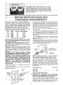
MOTOR SPECUFRCATIONS AND
ELECTRICAL
REQUIREMENTS
TtiiS rnachine is designed
to use a 3450 R.P.M. Motor only.
DOnot
use any motor that runs faster than 3450 R.P.M. It
is: wired for _peration
on 115 volts, 60 Hz., alternating
current; IT MUST
NOT BE CONVERTED
TO OPERATE
ON
230
VOLTS,
EVEN
THOUGH
SOME
OF THE
RECOMMENDED
MOTORS
ARE DUAL VOLTAGE.
This
THESE CRAFTSMAN
MOTORS
HAVE BEEN FOUND
BE ACCEPTABLE
FOR USE ON THIS TOOL.
This
plug requires
outlet as shown.
HP
1/2
1/2
_:3/4
RPM
3450
3450
3450
1/2, _
VOLTS
115
115
115
115
115
3450
CATALOG
12!6
1218
1219
1226
1269"
"MOtor has reversing
CAUTION:
Do notuse
or any motor with an automatic
their use may be hazardous.
CONNECTING
This
machine
Plug power
must
_ord idto
sa;_er fUse:o[:
ch:cuit
TO
protector
While in use to protect
a i 15v
properly
breaker.
If you:are
WARNING:
DO NOT
PERMIT
THE TERMINALS
OF PLUGS
REMOVING
THE PLUG TO OR
:grounded
the
Your
unit
plttg that
or cut, or damaged
125
_0Qr
S-PRoNG
volts and it has a
Extension
,
i
_
_:
CHECK
_
PRONG
lug to
electrician
grounded
\_
LUG
.........
_
t
CONNECTED
TO A
Cord
Wire Size AWG
Length
MOTOR
14
12
8
ROTATION
WARNING:
FOR YOUR
OWN SAFETY,
MAKE
SURE
PLUG
IS NOT
CONNECTED
TO
POWER
SOURCE
OUTLET
WHEN CHANGING
MOTOR ROTATION.
The
GROUNDING
the grounding
Up to100'
. .................................
100' to 200'
. ..................................
200' to 400'
. ................................
RouND II-Fn
o
Ui
OUT
connect
NOTE: The adapter illustrated is for useonly if you already
have a properly grounded 2-prong receptacle. Adapter is
not allowed in Canada by the Canadian Electrica! Code,
The use of any extension cord will cause some loss of
power, To keep this to a minimum and to prevent
overheating and motor burn-out, use the table below to
determine the minimum wire stze (A.W.G.) extension cord.
Use only 3 wire extension cords which have 3-prong
grounding type plugs and 3-pote receptacles which accept
the tools plug.
like this.
PROPERLY___
type
2-PRONG
RECEPTACLE
in any way, have
PLUG
cord and
grounded
you have a qualified
outlet with
a properly
ADAPTER
3-PRONG
i
3-conductor
FINGERS
TO TOUCH
WHEN
INSTALLING
OR
FROM
THE OUTLET.
is to be used on less than
looks
and always
GROUNb|NG
WARNING::
IF
NOT
PROPERLY
GROUNDED
THIS
POWER TOOL
CAN INCUR
THE POTENTIAL
HAZARD
OF
ELECTRICAL
SHOCK.
PARTICULARLY
WHEN
USED
IN
DAMP
LOCATIONS
IN
PROXIMITY
TO
PLUMBING.
IF
AN
ELECTRICAL
SHOCK
OCCURS
THERE
iS THE
POTENTIAL
OF A SECONDARY
HAZARD
SUCH AS YOUR
HANDS
CONTACTING
THE
CUTTER
BLADE.
If power cord is worn
it replaced immediately.
a 3-conductor
An adapter as shown below is available for connecting
plugs
to 2-prong receptacles.
The green grounding
lug extending
from the adapter must be connected
to a permanent
ground
such as to a properly
grounded outlet box.
as
type outlet
not: sure that
with
a mating
It is recommended
that
replace the TWO
prong
THREE prong outlet,
TO POWER SOURCE OUTLET
be grounded
is equipped
adapter as shown
known ground,
machi ne motors
reset overload
tool
If the outlet you are planning
to use for this power tool is
of the two prong
type
DO NOT REMOVE
OR ALTER
THE GROUNDING
PRONG
IN ANY
MANNER.
Use an
NO.
switch
blower or washing
power
grounding type plug which has a grounding prong, approved
by Underwriters'
Laboratories
and the Canadian Standards
Association.
The ground conductor has a green jacket and is
attached to the toot housing at one end and to the ground
prong in the attachment
plug at the other end.
motor
viewed
pulley.
according
must
from
(See
rotate
COUNTERCLOCKWISE
the shaft end to which
page 8) If it does not,
to the instructions
furnished
when
you will mount
the
change the direction
with
the motor.
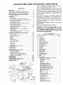
UNPACKmNG:
AND
CHECKING
Model
113.239291
one carton
CONTENTS
WARRANTY
................................
ShaPer
is shipped
Complete
in
2
Elevating Rod and Table Support
.......
Belt Guard and Motor to Motor Mount
+.
Motor Rotation
.....................
Motor Pulley
.......................
Motor Support Assembly
to Shaper .....
Mounting
Switch Assembly
...................
Assembling
Steel Legs .......................
Mounting
Wood Shaper on Floor Stand
............
Plugging in Motor
...........................
Installing Shaper Fence + For Straight
Edge
Shaping only ..............................
Installing Shaper Cutter Guard - For Curved
or Irregular Shaping only
....................
GETTING
TO KNOW YOUR WOOD SHAPER
......
On-Off Switch
.............................
Elevating Control
Lever ......................
Spindle
Lock Knob
.........................
Spindle
...................................
Spacers ....................................
Keyed Washer
.............................
Fence Adjusting
Knob
.......................
Fence Lock Knob
..........................
Fence Faces ...............................
Cutter Guard
..............................
Starting Pin
...............................
Removing and Installing Cutter
ADJUSTMENTS
..............................
Wood
and includes steel legs and motor.
Model
113.239201
Wood Shaper is shipped complete
in
one carton but DOES NOT INCLUDE
Steel Legs or Motor.
General Safety Instruction for Power Tools
.........
Additional
Safety Instructions
for Wood Shaper
.....
Motor Specifications
and Electrical
Requirements
....
UNPACKING
AND CHECKING
CONTENTS
.......
List of Loose Parts ..........................
ASSEMBLY
.................................
Tools Needed ..............................
Installing
Mounting
Checking
Installing
Mounting
CONTENTS
................
2
Separate
3
4
5
5
6
6
one with the illustration and the list of Loose Parts to make
certain
all items are accounted
for, before discarding any
packing material.
tf any parts are missing, do not attempt
to assemble the
Shaper, plug in the power cord or turn the switch on until
the missing parts are obtained and are installed correctly.
all
parts from
packing
materials
7
7
8
Remove the protective
and edges of the table.
grease and spot remover.
8
9
CAUTION:
Never
volatile solvents.
oil that is applied
Use any ordinary
use gasoline,
check
or similar
highly
Apply
1t
ALL
ASSEMBLY
STEPS ARE
COMPLETE,
AND
HAVE
READ
AND UNDERSTAND
THE SAFETY
OPERATIONAL
INSTRUCTIONS.
14
14
14
14
14
14
14
14
14
14
14
15
Shaper Fence
..............................
Fence Faces ...............................
BASIC SHAPING
OPERATIONS
.................
Use of Cutter Spacers ........................
15
15
16
t 6
Straight Edge Shaping
.......................
Shaping With Use of Miter Gauge and
Hold+Down
Clamp (Optional
Accessory)
.........
Irregular or curved Shaping
...................
MAINTENANCE
.............................
LUBRICATION
..............................
RECOMMENDED
ACCESSORIES
................
TROUBLE
SHOOTING
........................
REPAIR
PARTS
..............................
17
17
18
20
20
21
22
Wipe all parts thoroughly
WARNING:
CONNECT
FOR
PLUG TO
each
to the table top
household
type
9
10
10
11
11
13
!3
a coat of automobile
naptha
and
wax to the table.
with
YOUR
POWER
a clean, dry
cloth.
OWN
SAFETY,
SOURCE
OUTLET
NEVER
UNTIL
YOU
AND
LIST OF LOOSE PARTS
Included with Model No, 113.239201 and 113.239291
Item
A
B
C
D
E
F
G
H
J
K
L
M
N
0
P
Q
R
S
T
PartName
Motor Mount
Qty.
.............................
I
Guard, Pulley .............................
Pulley, Motor .............................
Belt, "'V'" 1/2 x 33 .........................
1
1
1
Support Assembly, R.H .....................
Support Assembly,LH ......................
Guard, Cutter .............................
Hub Assembly, Lock .......................
Nut, Lock ...............................
Stud Nut ................................
Support, Guard ...........................
Bracket, Support ..........................
Fence Assembly ...........................
Plate, Guard ..............................
Switch Box Assembly
......................
Spindle Assembly ..........................
Base ....................................
!
I
+
I
I
I
1
1
1
1
I
1
1
Owners Manua{ ...........................
Bag Assembly, Loose Parts (Part No. 72022)
Containing The Following:
Starting Pin .............................
Insert, Table ............................
Wrench ................................
Screw, Hex Hd. 3/8-1B x 1 .................
1
1
1
1
2
Washer
25164x 1-118x 7164 ...............
2
B01t+ Carriage 5/16-18 x 1-114 ..............
Washer 21]64 I.D. x 7 tB 0.D. x lib
..........
4
4
Screw, W/L0ckwasher 5]16-t8 x 3/4
.........
Washer11/321.D. x1+1116 x1/8
............
3
2
Wrench, Hex "L" 5]32 ....................
Wrench, Hex "L" I/4 .....................
Knob ..................................
Nut, Hex Jam 3/8-24
.....................
Screw, Hex Hd+ 5/16-18 x 1 1/_, ..............
Nut, Hex 5/16-18
........................
1
1
1
!
3
7
L0ckwasher, Int. 5]! B .....................
Hanger,Cable ...........................
Screw, He× Hd. 5/_6-18 x 2 ................
Elevating Rod ...........................
Washer 21/84 x 3/4 x 1/16 .................
3
1
2
1
5
Screw, Soc. Set 5/1E;..l_ x 5/1_
1
i ii:izzi
¸/:! ! iii
¸¸:,
¢
Induded With ModeiNo;: 113.239291
only
nty.
8
_=.Screw,Truss:Hd_Ii4o20x 5/B: ,,,:. .............
28
C
c:i:D_"
Nut,_
RexIJ4_2o
...:;.
........................
2B
....i:Loci(washer;
1/4:External.
_.;. :.:,. .... _=.,;L,.
28
B
...... E
F
..... G
.H
L
M
Cl_anneliSuppb_t i.,.
..........
.. ,. _,..,
Stiffener, i....!_.;...,,,,...
.... :.i...;
::-Stiffener;
Side .........................
Stiffener, End ..........................
e;Screw, Pan Hd. Ty, A N8 x 1/2 ............
Nut, HeXHd. 1/2-13 ....................
• Foot, Leveling ..........................
Motor .........
; ......................
2
2
2
2
4
B
4
1
A
:HARDWAREFOR MOUNTING TOOL
_
• Screw, Hex Hd, 5/16-18 x 3
• Lockwasher,5/lBExterna _!_:.ii_i_i_
oNut, Hex Jarn5/16-18 ...................
• Washer,11/32 ID .......................
3
3
3
3
• These parts contained in Loose Parts Bag No. 72031.
_----L
'
III
ASSEMBLY
i
TOOLS NEEDED
F RAMI
7/16-INCH
WRENCH
1 I2-1NCH
WR ENCH
9/16-_ NCH WRENCH
......
SCREWDRIVER
SCREWDRIVER
NG SQUARE
(MEDIUM}
(SMALL)
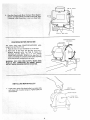
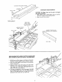
Coat the spindle assembly with cup grease, being sure to
wipe some of the grease into the elevating slot milled in the
spindle assembly.
TAPPED HOLE FOR
ELEVATING
ROD
SLOT
SPINDLE
6
PULLEY
INSTALLING
ELEVATING
AND TABLE
ROD
SUPPORT
Position
table upside down on 2 x 4's on edge for support
and clearance for spindle assembly.
1.
Install
(3/8-24)
jam nut on short
elevating
rod and screw the rod into
side of spindle assembly.
2.
Remove spindle
lock knob. htsert the spindle assembly
into the table support,
position the tong angle of the
elevating
rod straight
down
and
tighten
jam
nut
securely.
The angle portion
of elevating
rod must be
parallel with spindle assembly.
3.
Install
4.
Rotate
the set screw into
the table
support,
while
moving the elevating
rod back and forth,
until the dog
point
on end of set screw enters the elevating
slot in
spindle
assembly. This can be felt as the set screw and
spindle
assembly
are rotated.
Tighten
the set screw,
then back it off
1/4 turn.
This wilt allow
enough
clearance
for the spindle
assembly
slot to slide on
dog-point
end of set screw,
5.
Check
knob
on end of elevating
operation
of
spindle
threaded
end of
the threads in the
rod.
several
times,
by
moving
elevating
control
lever back and forth in order to make
sure it is not binding,
yet slides effectively
on the
dog-point
end of screw. Readjust set screw slightly,
if
requi red, for smooth operation.
Reinstall
6.
spindle
lock knob.
Position
shaper base on table support
casting so the
three mounting
holes are aligned. Install and tighten the
three
5/16-18
x 3i4dnch
hex-head
screws with
fock
washers.
POSITION
.5/8
IN.
DIA,
MOTOR
SHAFT
WITH
THiS
END
BELT GUARD
MOUNTING
BELT GUARD
TO MOTOR
1.
Place the motor
2.
Support
shown.
3.
rear
mount
of
MOUNT
on your
motor
AND MOTOR
mount
workbench.
with
3/4"
Find
four
5/16"
x 18 x 1-1/4
carriage
5/16-18
hex nuts, and two
2t/64
x 3/4
Washers. Position
hardware as shown.
x
stock
bolts,
1/16
as
four
Flat
MOTOR
3/4
IN.
STOCK
MOUNT
{
u
::
5/8 IN.
SHAFT
i1t,
:::4.; !: ::Place:':Belti::G_ard iunde_iMotor
(between; Motor Support
'
i:i B_a_ket and M0torll Mount )and makd certaln 518' shaft
:
:is Centeied in •Bblt Guard hoie. :inStall nuts finger tight,
?i!!
5/t6
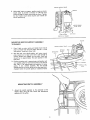
CHECKING
The
motor
viewed from
1. Place
2.
must
rotate
the PULLEY
the motor
Stand
MOTOR
clear
of
COUNTERCLOCKWISE
end.
the
NUTS
when
or on the floor.
motor
and
plug
outlet
shaft,
(see
If
Page 4). Notice
the
it
is
not
turning
properly,grounded
rotation
of the
HEX
COU NTERCLOCKW]SE
ROTATION
ROTATION
on your workbench
IN.
the
cord
into
a
COUNTERCLOCKWISE,
REMOVE
the plug from the
Outlet and change the:irotation of the motor according
tO the instructions
furnished with the: motor,
WARNING_
FOR YOUR
OWN SAFETY,
MAKE
SURE
PLUG
IS NOT
CONNECTEDi:TO
POWER
SOURCE
OUTLET
WHEN CHANGING
MOTOR ROTATION.
INSTALLING
1.
MOTOR
PULLEY
\
5/32 lN.
TSCREWWRENCH
Install motor pulley (flat-faced
pulley) on motor shah,
with closed end of pulley facing out. Tighten
pulley set
screw securely.
MOTOR
PULLEY
\
FLUSH WITH
END OF SHAFT
k• ••/,
:
•
.
MOTOR MOUNT
.
PLATE
MOTOR
Using table insert as a spacer, position motor on motor
mount
plate to provide
a distance
of 1/4-inch
from
mounting
edge of motor mount plate as shown. Tighten
the four motor
mount
bolts securely and recheck for
correct positioning.
MOTOR
PULLEY
(FLAT-FACE)
TABLE iNSERT
I/4
INCH
USED AS A SPACER
MOUNTING
MOTOR
TO SHAPER
MOTOR
SUPPORT ASSEMBLY
MOTOR
t.
PLace V-belt on motor pulley and attach motor mount
plate to shaper base with
two bolts (3/8-16
x 1-inch)
and washers. Leave bolts finger tight.
2.
Roll the belt onto spindle
pulley,
pull motor
mount
plate toward
end of base until belt is tight enough to
prevent
slipping and tighten
the two bolts. Each bolt
should
be in approximately
the same position
in the
base slots.
3.
Position
elevating
rod in approximate
mid position
and
turn spindle pulley by hand several times to see that the
belt rides in the approximate
mid position
of motor
pulley.
If not,
recheck
assembly.
The
belt should
change positions on motor pulley as the lever position is
changed
(while the spindte pulley
is rotated by hand).
MOUNTING
"J,
SWITCH ASSEMBLY
Attach the switch assembly to the underside of the
Shaper table using the two screws and lockwashers
packed with the switch.
MOUNT
SPINDLE
ELEVATING
ROD
PULLEY
PLATE
BASE
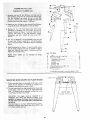
ASSEMBLING
STEEL
LEGS
: (Si_ppli_ With 113J2392910nly),
£
: :: 'Side::Stiffeners USi_ig::
f0ur: (4)i: i14;20 Truss heads_re_;
: Thel EndStiffeners;_are
placed cin: itop 0f each Side
::stiffener
as:shown.: !lfisert screws: thi0ugh: the 9/32 inch
i: :::di;_meter holes and finger tighten l:/4-20;nutS:
2_ Attach: the four (4) legS;'::tothe Sicle'_nd End Stiffener
{]singl_/4_20 screws, IOckwashers and nuts assh6wn:
•
3; Remove the four (4) Truss head screws which were
assembled in Paragraph No. Orie. Place the two (2)
Support Channels as Shown, in position, align holes in
supports with holes in the side Stiffeners,
replace
|ockw_shers and nuts. Tighten all nuts using 7/!6
wrench;
/
4: The two (2) Stiffeners, (F)iare fastened to the top side
of each side stiffener using N8 x 1/2 self-threading
screws. The guard plate is mounted as shown using same
screws.
Install leveling feet as shown. To level Leg Set, loosen
nut on inside of leg and turn nut on outside to raise or
lOWer feet, Adjust all four levelers, if necessary, and then
:'tighten nuts on inside of leg.
Item
NOTE_ These levelers ape not: intended
adjUstment._ "
for
height
A
8
C
D
E
F
Leg ..................................
e Screw, Truss Hd, I/4-20
x 5/8
.............
• Nut, Hex 1/4-20
........................
Lockwasher,
1!4 External
................
Channel,
Support ........................
Stiffener
..............................
G
H
j
K
L
Stiffener.
Side
........................
Stiffener,
End ..........................
• Screw, Pan Hd, TV- A N8 x 1/2 ............
• Nut, Hex Hal. 1/2-13
....................
• Foot, Leveling
.........................
• These
GUARD
MOUNTING
WOOD SHAPER ON FLOOR
Qty.
Part Name
parrs contained
in Loose Parts Bag No, 72031.
PLATE
STAND
t. Three mounting
holes are provided in the base of the
shaper for the purpose of mounting it securely on a
substantial tool stand with screws or bolts.
2. The tool stand should be high enough so the top surface
of the shaper table will be 35 to 37 inches above the
floor. The shaper must be mounted to allow the motor
to overhang rear edge of tool stand.
t
NO.
PAN
(SUPPL}ED
CAUTION:
The shaper must be mounted on a
substantial tool stand and secured so there is no
possibility of tipping. The Shaper must be positioned on
the toot:stand-so that the spindle pulley is guarded from
the bottom.
Place the Shaper on the Steel LEGS. PositiOn as shown,
and align mounting holes; SecUre with 3 ea. 5/16" x 18
x 3" screws;washers and nuts,
....
i=
..............
.....
10
8 X
HD,
WiTH
I/2 iN.
SCREW
LEG
SET)
4
28
28
28
2
2
2
2
4
8
4
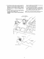
PLUGGING
1.
Find
2.
Route
plastic
the
cable
motor
hanger
cord
IN MOTOR
from
behind
among
the
motor
the loose parts.
mount,
across
the top of the Leg Set and plug it into the receptacle
the side;of the switch box.
3.
in
Bring
the
power
cord
alongside
the
motor
cord ... wrap the plastic cable hanger around the cords
and attach the hanger to the top of the Leg Set.
5/16-18
X 2 IN.
HEX HD. SCREWS
AND WASHERS
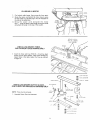
RNSTALLING
FOR STRAIGHT
1,
Instal_
the
fence
FENCE
SHAPER FENCE -EDGE SHAPING ONLY
with
two
5/16-18
x 2 inch
hex head
screws and two plain washers. These screws thread into
tapped
holes in the table. Adjust
the fence as outlined
on page 13.
GUARO
INSTALLING
FOR CURVED
SHAPER CUTTER GUARD OR IRREGULAR
SHAPING ONLY
HEX
NOTE:
1.
Fence must be removed.
Assemble
Cutter
Guard
as illustrated.
1t
HD,
SCR, EW
ki_:ii:i¸__;¸¸ :
!:!_-_:_i/:_::i:
¸¸!,I:I/i
_ _ .:_ _;:; :_::: _` :;_;_::_:::_;;j_
......
Aiign the guard _pportl _0 that it is:cer_teredon the shaper
spind e i(It may_ibe necessary to ioosen: the 5/16:18 ScreWs
Which: secure _the ii Support bracket :tO the channeis ito
perform this adjustment):; Af{er the :alignment is achieved
tighten all four SCrewSsecurely.
GUARD
InStall Cutter GUard:Assembly to table support using the
two 5/16:18 X:2 inch hex head screws located at rear of
table Support.
k
]2
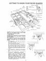
GETTING TO KNOW
YOUR WOOD
SHAPER
8
FENCE
LOCK
KNOB
9
FENCE
TABLE
MITER
FACE
INSERT
GAUGE
TABLE
\
STARTING
PIN
FENCE
ADJUSTING
KNOB
FENCE
2
_:LEVATI NG
CONTROL
LEVER
3
1
ON-OFF
\
MOTOR
SHAPER
MOTOR
KNOB
CAUTION: Before turning switch on, make sure the cutter
is installed properly and the keyed washer is positioned
below the spindle nut,
The On*Off Switch has a locking feature, THIS FEATURE
IS INTENDED
TO PREVENT
UNAUTHORIZED
AND
POSSIBLE HAZARDOUS
USE BY CHILDREN
AND
OTHE RS.
MOUNT
PLATE
BASE
a.
TO turn Shaper ON...
insert finger under switch lever
and putl END of lever out.
After turning switch ON, always allow the cutter to
come up to full speed before cutting.
Do not cycle the motor switch on and off rapidly, as
this may cause the cutter to loosen. In the event this
should ever occur; allow the cutter to come to a
complete stop and ret_ghten the spindle nut normally,
not excessively. Never leave the shaper white the power
is "ON".
b.
TO turn shaper OFF...
PUSH lever in. Never leave the
shaper until the cutting tool has come to a comptete
stop,
TO lock switch in OFF position...hold
switch 1N
with one hand ,. o REMOVE key with other hand.
ALWAYS
LOCK
THE
SWITCH "OFF"
WHEN
SHAPER IS NOT IN USE.,.
REMOVE KEY AND
KEEP IT IN A SAFE PLACE,,,
ALSO.,,
IN THE
EVENT OF A POWER FAILURE
(ALL OF YOUR
LIGHTS GO OUT) TURN SWITCH OFF ... LOCK IT
AND REMOVE THE KEY, THIS WILL PREVENT
THE SHAPER FROM STARTING UP AGAIN WHEN
THE POWER COMES BACK ON.
KEY
(YELLOW
I3
(NOT
FURNISHED)
CAUTION:
All set-up and operational instructions that
follow
(for the Shaper)
relate
to and
require
counterclockwise rotation of the spindle.
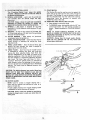
1. ON-OFF SWITCH
c.
SPINDLE
LOCK
SWITCH
PLASTIC)
FACE
2; :ELEVATING CONTROL LEVER , i ....
The :,Elevating ::i:co_troi Lever: : movesl _he: spindle
:vertically :a di_ait_:of,718:inch
to locate:the: cUttei;_;at:
the desired:vertical_i_Sition_
determined,
CAUTION: Always release the quill lock knob before
attempting to ichattge ithe iposition:of
Spindle
tighten the knob Secureiy before startinff operation. : ....
4. SPINDLE
L_ .This::=shaper is designed for use with
maximum
diameter
2Li/2-inch
bore.
diameter
cutters having
a l/2:inch
5_
SPACERSA total of three spacers are provided,
two
7/16inch
thick and one 1/4 inch think for positioning
the cutter for desired shapes.
6;
KEYED
7.
immediately
below the spindle nut;
FENCE ADJUSTING
KNOB
Each fence face may be
moved
forward
or backward
by turning
the fence
adjusting
8.
-
Must
always
be
positioned
CAUTION:
Always have the keyed washer directly
under the nut, otherwise the nut may loosen and
serious injury could resu|t.
knobs.
FENCE
LOCK
position
has
tightening
9.
WASHER
1 !, STARTING PIN
: :The Starting' Pin must be used as a pivot to support the
: i:iwork unti!:it has been fed into the cutter and against
the collar. The Starting Pin may be located in either of
the two threaded holes near the table insert opening,
depending
upon the direction of rotation, but
ALWAYS on the in-feed side.
12. REMOVING AND INSTALLING CUTTERS
a.
Raise:spind}e to maximum height
b. To REMOVE cutter, hold spindle with the 1/4" hex
wrench and loosen nut with wrench provided as
shownReverse procedure to TIGHTEN SPINDLE
NUT.
NOTE: TO AVOID
POSSIBLE BENDING OF THE
SPINDLE LOOSEN OR TIGHTEN NUT WITH BOTH
WRENCHES POINTING AS NEARLY IN THE SAME
DIRECTION AS POSSIBLE.
KNOB
been
-
After
selected,
the
the
desired
fence
fence
is secured
face
bY
the fence lock knobs.
FENCE FACES -- Each fence may be moved forward
or backward
by releasing
the fence lock
knob
and
turning
the fence adjusting
knobs.
Each fence face
operates independently
of the other,
by means of the
adjusting
mechanism.
After the desired fence position
has been selected, it is secured by tightening
the fence
lock
knob.
The fence
faces wilt
close
in from
a
maximum
three-inch
opening
down
to one-inch
for
Small diameter
cutters, by loosening
the two screws in
the front of each face and sliding the face to the desired
posiiton. The Screws must be tightened
securely after
each setting.
CAUTION;
The opening between inner ends of fence faces
ShOuld: never _be large_ than required to just clear the
particular cutter being used. ALWAYS
ROTATE THE
SPINDLE BY HAND BEFORE STARTING THE SHAPER
MOTOR TO MAKE SURE CUTTER DOES NOT STRIKE
FENCE FACES,
/
10. CUTTER GUARD
NOTE: Used for curved or irregular shaping only fence must be removed and starting pin must be in
place on in-feed side.
Provides added protection for irregular shaping. Guard
is adjustable for various thickness of material.
WRONG
CAUTION; Always rotate the spindle by hand before
starting the shaper motor to make sure cutter does not
strike guard,
•
•-•::::i:: • •: •••:• O••::• •• :• •:
RIGHI"
• :__-•i _•:•i: • :• •
:'14. ¸
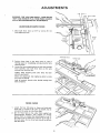
ADJUSTMENTS
WARNING:
FOR YOUR OWN SAFETY, TURN SWITCH
"OFF." AND REMOVE PLUG FROM POWER SOURCE
OUTLET BEFORE MAKING ANY ADJUSTMENTS.
ADJUSTABLE
1.
Move both fence
faces
fence adjusting
knobs.
SHAPER
out
3/4"
FENCE
by turning
the
two
FENCE
ADJUSTING
KNOBS
STRAIGHT
EDGE
FENCE
2.
Position
fence
framing
square
adjusting knob.
3,
Loosen the fence attaching bolts and shift the complete
fence assembly
until
both fence faces are the same
distance from the miter slot.
Tighten
correctly
faces in the
or straightedge
fence
attaching
positioned.
Check this adjustment
sure it did not change.
Lock all controls
been completed.
same plane by using a
and adjusting
the fence
bolts
after
securely
after
fence
tightening
after
desired
bolts
has
been
to
make
settings
have
FENCE FACES
Loosen
the four
(4) screws as shown and slide each
fence face in as close to the cutter as possible, but do
not permit the cutter to strike fence faces.
1°
,
Set
the
fence
faces
so the
cutter
(Not
supplied
see
Recommended
Accessory
List)
projects
far enough
beyond
them to produce
the desired depth of cut. if
the cutter is set to remove only a portion
of the edge of
the work piece, the two fence faces should be set even
with each other.
15
FACE
BA SiC SHAPING; O PERATION
cutter would
S
have to be turned over.
2i :Always remember (when mounting
the cutter) that the
cutting edge of cutter
must lead into the direction
of
rotation;
Instructions:_:for
: reversing
the
motor
rotation
are
normally
:foUnd On the motor
name plate, or electrical
cover plate. Make sure the plug has been removed
from
electrical:outlet
before attempting
to reverse rotation.
SPINDLE
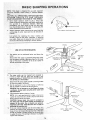
USE OF CUTTER
1; The
spacers
cutter,
can
SPINDLE
SPACERS
be positioned
below
and
above
the
y
KEYED
Notice when the spacer is positioned
below the cutter
how the spacer proVides a bearing surface for the uncut
edge of the board, in addition
to its use as a spacer in
vertical positioning
of the cutter.
DIRECTION
OF FEED
WASHER
"_CUTTER
__SPACER
/
2;:This
same :cutter
produce a Shape
ooposite direction
THE SPINDLE IS
f
k
TABLE INSERT
can be inverted
and mounted to
with the board fed through in the
I F DIRECTION OF- ROTATION OF
REVERSED,
Notice how the spacer again provides a bearing surface
for the uncut edge of the board.
3. Cut the workpiece to size, so the shaping cut will be as
light as possible to produce the desired pattern.
CAUTION: Do not attempt to usethe Shaper for sizing
a workpiece (except when using the jointer cutter and
adjustable fence).
4. Feed workpiece against rotation of cutter.
NOTE: It is a very good practice to make a trial cut on
a piece of scrap wood as a double check on the set-up
before usingthe actual workpiece.
CAUTION: Serious injury may result if workpiece is
not always fed into the cutter against the direction of
rotation of the cutter, Use a smooth even pressure.
Experience will:soon reveal the best rate of feed for
producing rite Smoothest cut,
5. If :the :Cut removes materia_ Over the entire ed
reducing the Width 0f_t!_e work
fence ir_ fron_
enough:to provid,
it passesthee:utter: This!
mg
to
support the workpiece.
/ SPACER
DIRECTION
OF FEED
:i •. • •
.
• :
DIRECTION
OF
ROTATI 0 N
NOTE: TABLE INSERT
REMOVED
•16
" :
/
AUXILIARY
FENCE/WORK
SUPPORT
WORKPIECE
X
STRAIGHT
2,7 IN,
EDGE SHAPING
CAUTION: The Shaper fence must be used in all straight
edge shaping operations.
1. When shaping stock 3 inches wide or tess, an auxiliary
fence/work support must be used as shown.
2,
Make
the push stick
as shown.
I
SLIGHTLY THICKER
THAN WORKPfECE
PUSH STICK
(FEEDS UNDER
AUXILIARY
_ENCEi
WORK SUPPORT
AUXiLiARY FENCE!
WORK SUPPORT
,\
SLIGHTLY
NARROWER
FENCE
2O
PUSH STICK
WO_KPI ECE
END SHAPING WITH USE OF MITER GAUGE AND
HOLD-DOWN CLAMP (OPTIONAL ACCESSORIES)
1.
NEVER
Hold-down
use the Miter
Clamp
Gauge on the Shaper without
installed
and the workpiece
be positioned
the
clamped.
2.
Both fence faces MUST
cannot contact them.
so the workpiece
3.
Adjust
the head of the miter gauge so the end of the
workpiece
to be shaped will be exactly parallel to the
miter gauge slot in the table, This holds true for all
angles of the end of the workpiece,
4.
The board is positioned
in the miter gauge; then hold
the workpiece
firmly
against the miter gauge head and
down on the table with your left hand, and feed by
gripping the lock handle with vour right hand.
17
THINNER
THAN
AND
WORKPiECE
,."EGUL ROR
C RVES. PmG
DIRECTION
OF FEED
DIRECTI(
OF
workpiece; by using various combinations of cutters on
successive passes, and/or by invertlng Cutterand changing
direction of spindie: rotati0n and: feedidirectibn_ Tile table
insert:must be removed if the cutter does not ctearthe hole
in the insert when the cutter is lowered below the table
surface:check clearance before turning switch "ON":
t; To make irregular shaping cuts remove power cable
from electrical source, remove the fence assembly,
select the shaper collar that wit! position the cutter to
obtain the desired pattern, and lock the shaper collar
and Cutter onthe spindle.
NOTE: A shaper collar may be located above or below
a cutter, or between the two cutters selected.
SHAPER COLLAR
(OPTIONAL
ACCESSORY)
o
©
SHAPER COLLAR
(OPTIONAL
2.
Mount the cutter guard and adjust as shown.
Position the: Guard verticalli (A) (Guard should just
clear workpiece)
Center the Guard over the cutter. (B)
NOTE: Rotate cutter by hand and check for proper
clearance inside guard.
STARTING(-
/
i
._: c•• : •_..• _
/
SET
ACCE SSORY)
/
3.
4.
The starting
pin must be used as a pivot to support
the
work
until it has been fed into the st_aper collar. The
Starting
Pin may
be located
in either
of the two
threaded
holes near the table insert opening, depending
upon the direction
of rotation;
but always
on the
in-feed side.
Workpiece
MUST contact
collar - toward the miter
5.
Start the workpiece
by pivoting
it around the starting
pin
slowly
into
the path of the cutter
until
the
workpiece
contacts the shaper collar.
WARNING:
LUMBER.
DO NOT
ATTEMPT
of the cutter
WORKPIECE
STARTING
PIN
COLLAR
POSITION J
19
and
in addition,
the following
operations
are some which
can be performed
on the shaper
- shaping with
a
pattern,
tongue
and groove joints,
reading and fluting,
etc.
("Power
Toot
Know
How"
Handbooks
are
available)
See Recommended
Accessories list.
NOTE: After a few hours of operation,
tighten both
set screws securely with the Hex wrenches provided.
TO SHAPE WARPED
PIVOT
AROUND
the FRONT
gauge slot.
pulley
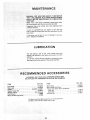
MAINTENANCE
:i_¸ !j: :i
WARNING:
FOR YOUR
OWN
I?OFF_
AND REMOVE
PLUG
OUTLET
BEFORE:MAINTAINiNG
YOURSAW,I
:
SAFETY,
TURN
SWITCH
FROM
POWER
SOURCE
OR LUBRICATING
NOTE: After a few hours of operation, tighten
both pulley
set screws securely withthe
Hex wrenches provided.
Frequently
clean your cutting
and Pitch Remover,
tools
with
Craftsman
Gum
A coat of automobi]e-type
wax applied
to the table wil!
help to keep the surface clean and allow workpieces
to slide
more freely.
If the power cord is worn or cut,
have it replaced immediately.
or damaged
in any way,
LUBRnCATION
The ball bearings
used on the cutter
spindle
packed with lubricant
at the factory
and require
attention,
have been
no further
To maintain
smooth and easy operation,
occasionally
add a
few drops of oil tothe outside of the spindle assembly.
RECOMMENDED
ACCESSORIES
IN CANADA, SEE YOUR LOCAL SIMPSONS-SEARS STORE
OR CATALOG FOR ACCESSORY SELECTION AND NUMBERS
ITEM
CAT.
Floor Base .................................
Steel Legs ..................................
Casters ............................
Shaper Collar Set ...........................
Shaper Cutters
.........................
Push Blocks .................................
Motor W/Reversing Switch ...................
:i ii :
i_
NO.
CAT.
ITEM
9-22213
9-22236
9-22222, 9-22221
9-23672
See Catalog
9-2299
9-1269
Miter Gauge .............................
Miter Gauge Hold Down ....................
"Power Tool Know How" handbooks
Table Saw ..............................
Radial Saw ..............................
Universal Jig .. _...........................
The above recommended
accessories
are current
available
manual
_rinted.
at the time:this
was
and were
NO.
9-29929
9-29928
9-2918
9-2917
9-3231
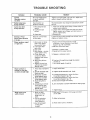
TROUBLE
PROBABLE
TROUBLE
SHOOTING
REMEDY
CAUSE
iii ,,
,,, ,,,,,,,
Spindle
Assembly actuates
too hard.
Set screw engaging slot
in spindle assembly
too tight,
Tighten
Cutter
comes loose
during
operation.
Keyed washer not
properly
installed.
The keyed
the nut,
1, Work being fed too
rapid I%
2, Insufficient
belt
tension.
i '.'F'eed work through
more slowly to allow cutter to
remove stock smoothly.
2. Loosen motor mount
plate bolts and move motor
slightly
toward rear of shaper until belt tension is
correct,
tighten bolts.
3, Replace belt.
Cutter slow down
during operation.
3. Glazed
Bottoms
belt
of fence faces
Binding of Fence
Boards when adjusting
in or out,
striking
table,
Shaper
1. Work
piece not being
produces ragged
action
2. Interrupted
and tighten
,
5.
6.
sufficient
always be used directly
through
front
hand pressure
or revise Auxiliary
Support
Maintain
(pg. 15) accordingly.
continuous
feed.
or resharpen
7. Use a better
1.
Adjust
until
under
of face, raise it
in _c)th
Fence/Work
cutter.
slow enough
to produce
grade of material.
fence faces,
2. Tighten
knob not tight.
Workpieoe
not held
snugly against fence,
Work piece not held
snugly against table.
Work being fed to
rapicJly.
Attempting
to remove
more material than
spindle
assembly
lock
knob,
3. Increase hand pressure or revise Auxiliary
Fence/Work
Support
(10g. 15),
4, Increase hand pressure or revise Auxiliary
Fence/Work
Support
(pg, t 5),
5.
Feed work
6. Joint
required to produce
desired shape,
7. Fence loose on table,
1. Work
Adjust
screws.
6. Feed work through
smooth cut,
1. Fence faces improperly
set.
2. Spindle Assembly
lock
4.
screws
turn,
end piay.
directions
5. Replace
rapidly.
7. Quality of wood not
sufficient
to produce
desired results.
3.
must
it off 'i/4
3. Sharpen or replace cutter
4. Adjust belt for proper tension.
segments have uneven
lengths.)
6. Work being fed too
Shape varies across
width of board.
the two
feed
4. Belt slipping - causing
cutter speed to vary.
5. Cutter blades not
concentric.
(Blade
Shaper produces a
smooth cut, but does
not hold a straight edge.
washer
Apply
back
without
slightly
I,
past cutter.
3. Dull cutter.
is smooth
Loosen
held firmly against
fence and/or table.
or ripple cuts.
screw then
workpiece
7. Tighten
not held
through
to proper
securely to miter
gauge and/or to
table.
2. End of workpiece
2. Adjust
not parallel with
miter gauge slot.
3, End to be shaped
3. Resaw and/or
21
width
before
shaping
fence.
I. Hold work firmly
on the table.
is wavy (not
straight).
more slowly,
miter
against
miter
gauge.
joint
as necessary.
gauge and down
edge.
R EPAIR:: PARTS
I
I
!
I
§
I
!
I:
36.__.._ _
40
41
|
|
|
g
|
g
g
H
42
6
37 =
I
!
I
ii
i
44
i
91
I
g
II
g
t
"'38
35
\
(used
22
with
9-22236
Steel
Leg
Set)
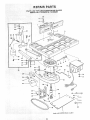
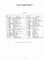
PARTS LIST FOR CRAFTSMAN WOOD SHAPER
MODEL No. 113.239201 & 113.239291
FIGURE 1
Key
No.
1
3
4
5
Part
No,
Ke! '
No
Description
72008
60167
STD 623120
39411
39613
39290
39512
STD 551037
STD 54t 137
39629
60437
38799
39628
38546
Fence Assembly
(See Figure 2)
Washer, .343 x 1.062 x 1/8
*Screw, Hex Hd. 5/16-18 x 2
Insert, Table
Pin, Table Dowel
Table (Includes
Nameplate}
Knob, Lock
*Washer, 13/32 x 47/64 x t/16
*Nut, Hex, Jam, 3/8-24
Stud, Lock
*Washer, 2t/64 x 7/8 x 1/8
Screw, Set, 3/8-24 x 3/4 Dog Pt.
Rod, Elevating
Knob
Switch Box Assembly
(See Figure
STD 55! 210 * Lockwasher,.lnternal
No. 10
STD 511 t05 *Screw, Pan Hal. 10-32 x 1/2
39215
Base
J
10
11
12
13
!4
1
17
t8
19
20
21
22
23
24
25
26
4)
Spindle Assembly
(See Figure 5)
72014
Plate, Guard
STD 304330 *Belt, V, I/2 x 33
STD 533t 12 *Bolt, Carriage 5/16-18 x 1-1/4
STD 55t 031 *Washer 21/64
STD 541231 *Nut, Hex 5/16-18
39217
453068
27
28
72003
STD 503102
29
30
31
32
33
34
35
36
37
38
39
40
41
39230
STD 551037
STD 523710
39216
72027
72024
72025
STD 551231
STD 523112
72005
42
43
44
45
46
47
48
56634
72026
72023
68036
37435
37837
38713
72022
Mount, Motor
Screw, Mach., 5/16-18 x 3/4,
Hex. Hd. w/Lockwasher
*Standard
Hardware
Items-
Part
No.
23
Description
Guard, Pultey
*Screw, Set 5/t6-18
x 5/16,
Soc. Hd. Cup Pt.
Pulley, Motor, (w/Set Screw)
Washer, 25/64 x 1-9/64 x 7/64
*Screw, Hex Hd. 3/8-16 x 1
Support Tabre
Guard, Asm. Cutter
Support Assembly,
R.H.
Support Assembly,
L.Ho
* Lockwasher,
tnternat 5/16
Screw, Hex Hd. 5/16 x !8x
1-t/4
Guard, Cutter
60262
I.Grip
STD 541525
Nut, Lock 1/4-28
70007
Hub Asm. Lock
72033
May be Purchased
!
i
Loca!ly.
i Stud,
Includes
Nut Key No. 39 )
Arm, Guard
Holder, Guard
Hanger,
*Wrench,
*Wrench,
Wrench
Cable
He×., t/4
Hex., 5/32
Bag Asm. Loose Parts
(not illustrated)
Owners
Manual
(not
illustrated)
7
9
\
12
11
FIGURE
2 -- FENCE ASSEMBLY
: Key
No.
!
:
::
:
"
3 138612
41t:t8451-I
5::138413
6
1 38531 .....
7 _ 381:10
9
38533
.
t0
S'£D 512507
11
STD 551012
t2
38532
Hardware
72008
Description
:I
72008::
*Standard
10
Fence Assembly Complete
x 1/2
K_ob, Adjusting
Washer, Spring
•
Frame
{i Knob
Shoe Assy., Fence
Plate,
Work Face (Right)
*Screw, Pan Hd., 114-20 x 3/4
*Washer, Plain, 1/4
Plate, Work Face (Left)
Item
-- May be Purchased
24
Locally.
PARTS LIST FOR CRAFTSMAN WOOD SHAPER
MODEL No, 113.239201 & 113.239291
2
L
FIGURE 3-
Key
No.
LEGS (Supplied with 113.239291
Part
No,
Description
i
1
2
3
4
5
6
7
8
9
10
11
12
62614
60314
STD541025
STD551225
68060
72030
68059
62615
ST D610805
STD541050
803835
72029
HARDWARE
,i
Leg
OScrew, Truss Hd. 1/4-20 x 5/8
e_ Nut, Hex 1/4-20
o* Lockwasher, 1/4 External
Channel, Support
Stiffener
Stiffener, Side
Stiffener, End
®*Screw, Pan Hd. Ty. A N8 x 1/2
o* Nut, Hex Hdo 1/2-13
• Foot, Leveling
t Motor
FOR MOUNTING
STD523130
STD 551131
ST0541231
STD551031
only)
Standard Hardware Item - May be purchased
!ocatly.
Stock Item - May be secured through the
Hardware
Department
of most Sears Retail
Stores or Cata;tog Order Houses,
TOOL
These parts contained
No. 72031.
• Screw, Hex Hd, 5/16-t8 x 3
e* Lockwasher, 5/16 External
• Nut, Hex Jam 5/16-t8
• Washer, 11/32 ID
25
in Loose Parts Bag
J
• •ii :L_;:i/•
;•. ":k
i_/•i•!.i i¸
8
f
J
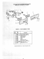
FIGURE 4ON/OFF POWER OUTLET 60382
AND MOUNTING BRACKET
'Key;
No,
-Pa,t
i_ .
No,
i
Description;
I
i
60375
_
211 6037811;
: 3 _' 60256
160376
=
Cord, Molded
Housing,Switchi_
:: I • Key;Switch
:
6o374
ii: 51
i
....
i
.....
i
:
i
i
I SwitchiLocking
:
::
SwitCh;i:;
;=
7
•
=
:
FIGURE
*Standard
Hardware
Does Not Include
Order Separately
Item
- May be Purchased
Locally.
Key
No.
Key No. 3
If Required.
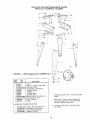
5 - SPINDLE
Part
No.
Description
r
R
!
2
3
4
5
6
39615
39711
39616
39617
72007
STD 503103
STD 328011
*Standard
k-
•i::••• ••: •i•••" " •i/•:
ASSEMBLY
i••••:: •i •• ••
••
:;
• .
26
Hardware
i
.
Spindle Assembty
Complete
Nut, Spindle
Washer, Keyed
Spacer 1/4
Spacer 7/t6
Spindle Assembly
*Screw, Set 5/16-18 x 3/8,
Soc. Hd. Cup pt.
*Pulley, (w!Set Screw)
2 x 1/2 Bore
Item
"V"
- May be Purchased
Locally.
NOTES
27
WOOD
SERVmCE
SHAPER
Now that you have purchased your wood shaper, should a need
ever exist for repair parts or service, simply contact any Sears
Service Center and most Sears, Roebuck and Co. stores. Be sure
to provide all pertinent facts when you call or visit.
MODEL NO.
113.239201
SHAPER ONLY
The model number of your wood shaper will be found on a
plate attached to your wood shaper on the front of the table.
113.239291
SHAPER WITH STEEL
LEGS AND MOTOR
HOW TO ORDER
REPAIR PARTS
WHEN ORDERING
REPAIR
FOLLOWIN3 INFORMATION:
PaN No. 72033
ALWAYS
GIVE
PART NUMBER
PART DESCRIPTION
MODEL NUMBER
113.239201
113.239291
NAME OF ITEM
WOOD SHAPER
All parts listed may be
and most Sears stores.
locally, your order witl
Repair Parts Distribution
Sold by SEARS,
PARTS,
ROEBUCK
Form
AND
ordered from any Sears Service Center
If the parts you need are not stocked
be electronically
transmitted
to a Sears
Center for handling.
CO., Chicago,
No. SP4462-6
THE
IL. 60684
Printed
U.S.A.
in U.S.A,
11/82