1
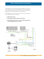
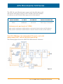
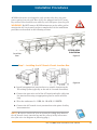
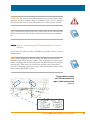
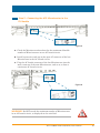
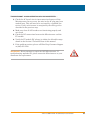
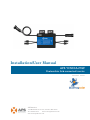
Installation/User Manual
APS YC500A-MIW
Photovoltaic Grid-connected Inverter
Version 2.4 2/17/13
APS America
1015 Hostmark St. Ste 104; Poulsbo, WA 98370
TEL: 206-855-5100
EMAIL: [email protected]
WEB: www.apsamerica.com
Table of Contents
IMPORTANT SAFETY INSTRUCTIONS
1
APS Microinverter System Introduction
2
APS Microinverter 500 series Introduction
4
APS Microinverter System Installation
5
Additional Installation components from APS
5
Required Parts and Tools from installer
5
Installation Procedures
6
Step 1 - Installing the AC Branch Circuit Junction Box
6
Step 2 – Attaching the APS Microinverters to the Racking
or the PV Module Frame
7
Step 3 - Connecting the APS Microinverter to the PV Module
8
Step 4 - Ground the System
9
Step 5 –Connecting APS Microinverters to the AC Cables
10
Step 6 - Completing the APS Installation Map
11
APS Microinverter system operating instructions
12
Troubleshooting
13
• Status Indications and Error Reporting
13
• Operation LED
13
• GFDI Error
13
• Other Faults
13
Troubleshooting a non-operating APS Microinverter
Replace a Microinverter
14-15
16
Technical Data
17-18
Warranty Regulation and Liabilities
19
Wiring Diagrams
20
• Sample Wiring Diagram – 120V/240V Split Phase
20
• Sample Wiring Diagram – 120V/ 208V Three Phase
21
• Sample Wiring Diagram – 277V/480V Three Phase
22
APS YC500-MIW Installation/User Manual
iii
IMPORTANT SAFETY INSTRUCTIONS
SAVE THESE INSTRUCTIONS! This manual contains important
instructions to follow during installation and maintenance of the APS
Photovoltaic Grid-connected Inverter (Microinverter). To reduce the
risk of electrical shock and ensure the safe installation and operation
of the APS Microinverter, the following symbols appear throughout
this document to indicate dangerous conditions and important safety
instructions.
WARNING: This indicates a situation where failure to follow instructions may cause a serious hardware failure or personnel danger if
not applied appropriately. Use extreme caution when performing this
task.
WARNING
SYMBOL
NOTE: This indicates information that is important for optimized
Microinverter operation. Follow these instructions closely.
NOTE
SYMBOL
SAFETY INSTRUCTIONS
✔✔ Do NOT disconnect the PV module from the APS Microinverter without first disconnecting the AC power.
✔✔ Only qualified professionals should install and/or replace APS Microinverters.
✔✔ Perform all electrical installations in accordance with local electrical codes.
✔✔ Before installing or using the APS Microinverter, please read all
instructions and cautionary markings in the technical documents
and on the APS Microinverter system and the PV-array.
✔✔ Be aware that the body of the APS Microinverter is the heat sink
and can reach high temperatures. To reduce risk of burns, do not
touch the body of the Microinverter.
✔✔ Do NOT attempt to repair the APS Microinverter. If it fails, contact
Blue Frog Customer Support (206-855-5100) to obtain an RMA
number and start the replacement process. Damaging or opening
the APS Microinverter will void the warranty.
APS YC500A-MIW Installation/User Manual
1
APS YC500A-MIW Introduction
Congratulations on your decision to purchase APS YC-series microinverters! When purchased with the APS ECU, this system will improve
safety, maximize solar energy harvest, increase system reliability and
simplify your PV system maintenance and management.
The APS Microinverter is used in utility-interactive grid-tied applications, comprised of three key elements:
✹✹ APS Microinverter
✹✹ APS Energy Communication Unit (ECU)
✹✹ APS Energy Monitor and Analysis (EMA) web-based
monitoring and analysis system
Figure 1
APS YC500A-MIW Installation/User Manual
2
APS Microinverters maximize PV energy production
Each PV module has individual Maximum Peak Power Tracking
(MPPT) controls, which ensures that the maximum power is exported to the utility grid regardless of the performance of the other PV
modules in the array. When PV modules in the array are affected by
shade, dust, orientation, or any situation in which one module underperforms compared with the other units, the APS Microinverter ensures top performance from the array by maximizing the performance
of each module within the array.
More reliable than centralized or string inverters
The distributed APS Microinverter system ensures that no single
point of system failure exists across the PV system. APS Microinverters are designed to operate at full power at ambient outdoor temperatures of up to 149°F (65°C). The inverter housing is designed for
outdoor installation and complies with the IP65 environmental enclosure rating.
Simple to install
You can install individual PV modules in any combination of module
quantity, orientation, type, and power rate.
Smart system performance monitoring and analysis.
The APS Energy Communication Unit (ECU) is installed by simply
plugging it into any wall outlet and providing an Ethernet or Wi-Fi
connection to a broadband router or modem. After installing the ECU,
the full network of APS Microinverters automatically reports to the
APS Energy Monitor and Analysis (EMA) web server. The EMA software displays performance trends, informs you of abnormal events,
and controls system shutdown when it is needed. (See ECU manual
for instructions.)
APS YC500A-MIW Installation/User Manual
3
APS Microinverter 500 Series
The APS 500 series Microinverters connect with the Split-phase grid,
and operate with most 60 and 72 cell PV modules. For more information, please see the Technical Data page (p.18) of this manual.
MODEL NUMBER
YC500
AC GRID
PV MODULE
MODULE CONNECTOR
60Hz/240V
60,72 Cell MC-4 Type or Customize
Maximum units per branch of YC500
Max. parallel combination of APS modules = 10/branch for 25 A breaker (20 PV modules)
Max. parallel combination of APS modules = 8/branch for 20 A breaker (16 PV modules)
The APS YC500 has two independent DC inputs, each with
independent MPPT control and data monitoring.
The following figure shows the APS YC500 Microinverter schematic:
Figure 2
APS YC500A-MIW Installation/User Manual
4
APS Microinverter System Installation
A PV system using APS Microinverters is simple to install. Each Microinverter easily mounts on the PV racking, directly beneath the PV
module(s). Low voltage DC wires connect from the PV module directly
to the Microinverter, eliminating the risk of high DC voltage. Installation MUST comply with local regulations and technical rules.
WARNING: Perform all electrical installations in accordance with
local electrical codes.
WARNING: Be aware that only qualified professionals should install
and/or replace APS Microinverters.
WARNING: Before installing or using an APS Microinverter, please
WARNING: Be aware that installation of this equipment includes
read all instructions and warnings in the technical documents and on
the APS Microinverter system itself as well as on the PV array.
the risk of electric shock.
WARNING: Do not touch any live parts in the system, including the
PV array, when the system has been connected to the electrical grid.
Additional Installation components from APS
✹✹ AC branch end cable (1 per branch, sold separately)
✹✹ Protective end cap (1 per branch, sold separately)
Required Parts and Tools from Installer
In addition to your PV array and its associated hardware, the following tools are required for assembly:
✹✹
✹✹
✹✹
✹✹
✹✹
✹✹
One AC connection junction box
Mounting hardware suitable for module racking
Sockets and wrenches for mounting hardware
Continuous grounding conductor and grounding washers
Phillips screwdriver
Torque wrench
APS YC500A-MIW Installation/User Manual
5
Installation Proceduress
APS Microinverters are designed to only operate when they can sense
power coming from the grid. Even if they are plugged into the PV array,
they will not turn themselves on until they can read power from the grid.
WARNING: Do NOT connect APS Microinverters to the utility grid or
energize the AC circuit until you have completed all of the installation
procedures as described in the following sections.
YC500-MIW
Installation
To
Junction
box
Figure 3
Step 1 - Installing the AC Branch Circuit Junction Box
A. Install an appropriate junction box at a suitable location on the
Figure 4
PV racking system (typically at the end of a branch of modules).
B. Connect the open wire end of the AC branch end splice cable into
the junction box using an appropriate gland or strain relief fitting.
C. Wire the conductors: L1- RED; L2 - BLACK; N -WHITE.
D. Connect the AC branch circuit junction box to the point of utility
interconnection.
NOTE: Be sure to size the AC wire to account for voltage drop between
the AC branch circuit junction box and the point of utility interconnection. (See wire size diagram on following page.)
APS YC500A-MIW Installation/User Manual
6
YC500 Number per Branch
2
3
4
5
6
7
8* 9
10**
EXTERNAL WIRE
SIZE (AWG)
MAXIMUM EXTERNAL CABLE LENGTH (ft)
12
370.7
237.1
167.9
124.3
93.6
70.2
51.4
35.7 22.1
10 593.1
379.4 268.6
198.9
149.7
112.3
82.3
57.1
8
926.8
592.9 419.6
310.7
233.9 175.5 128.6
89.3 55.4
6
1482.8
948.6 671.4
497.1
374.3 280.8 205.7
142.9 88.6
35.4
*8 is the maximum number/branch with a 20 amp breaker
** 10 is the maximum number/branch with a 25 amp breaker
Step 2 – Attaching the APS Microinverters to the Racking or the PV Module Frame
Figure 5
A. Mark the location of the Microinverter on the rack, keeping in
mind the PV module junction box or any other obstructions.
B. Mount one Microinverter at each of these locations using hard-
ware recommended by your module racking vendor.
C. GROUNDING WASHER: If using the appropriate grounding
washer (check with a licensed electrician); attach the grounding washer between the frame and the Microinverter.
WARNING: Prior to installing any of the Microinverters, verify that
the utility voltage at the point of common connection matches the voltage rating on the Microinverter label.
APS YC500A-MIW Installation/User Manual
7
WARNING: Do not mount the Microinverter in a location that allows
exposure to direct sunlight. Allow a minimum of 3/4” (1.5 cm.) between
the roof and the bottom of the Microinverter to allow proper air flow.
NOTE: Connecting cables (steps 3-5) can be done in any order but DO
NOT connect to the utility power grid until all the steps are completed.
Step 3 – Connecting APS Microinverters to the PV
Module
Connect the DC cables from the PV Modules to the Micro-Inverter per the
diagram below:
Note: When plugging in the DC cables, the Microinverter should
immediately blink green three times. This will happen as soon as the
cables are plugged in and will show that the Microinverter is functioning correctly. This entire check function will start and end within 5
seconds of plugging in the unit, so pay careful attention to these lights
when connecting the DC cables.
Photovoltaic panels
and Microinverter DC
input cable connection
Figure 6
- +
+ APS YC500A-MIW Installation/User Manual
8
WARNING: Insure that all AC and DC wiring is correct. Check that
none of the AC and DC wires are pinched or damaged. Be sure that
all junction boxes are properly closed.
Step 4 - Ground the System
NOTE: If you already use grounding washers (WEEB) to ground the
Microinverter chassis to the PV module racking as described in Step
2C, skip this step.
Figure 7
Each APS Microinverter comes with a ground clamp that can accommodate a single #6 awg strand and #4 awg solid conductor. Check your
local electrical code for grounding conductor sizing requirements. Connect the grounding electrode conductor to the microinverter ground
clamp.
NOTE: The AC output neutral is not bonded to ground inside the
microinverter.
APS YC500A-MIW Installation/User Manual
9
Step 5 - Connecting the APS Microinverter to the
PV Module
Figure 8
A. Check the Microinverter datasheet for the maximum allowable
number of Microinverters on one AC branch circuit.
B. Install a protective end cap on the open AC connector of the last
Microinverter in the AC branch circuit.
C. Plug the AC female connector of the last Microinverter into the
male connector of the next Microinverter, and so on, to form a
continuous AC branch circuit.
Figure 9
WARNING: Do NOT exceed the maximum number of Microinverters
in an AC branch circuit, as displayed on the unit label.
APS YC500A-MIW Installation/User Manual
10
Step 6 - Completing the APS Installation Map
Fill in the APS Registration Cards, which provide system information and the installation map. Feel free to provide your own layout
if a larger or more intricate installation map is required. The layout
map provided is designed to accomodate labels in vertical or horizontal
orientation to meet all the field PV connections.
1. Each APS Microinverter has removable serial number labels.
Peel a label off, and affix it to the respective location on the
APS installation map.
2. Fill out the warranty cards and email to APS at emasupport@
altenergy-power.com
3. APS will create the EMA account and email you the account in-
formation. Then you can use the EMA website to view detailed
performance of your PV system.
Figure 10
APS YC500A-MIW Installation/User Manual
11
APS Microinverter System Operating Instructions
To operate the APS Microinverter PV system:
1. Turn ON the AC circuit breaker on each Microinverter
branch circuit.
2. Turn ON the main utility-grid AC circuit breaker. Your system
will start producing power after a two-minute wait time.
3. Within 2 to 5 minutes of turning on the AC circuit breaker, the
units should start blinking green every 2 seconds. This means
they are producing power normally, but have not yet connected
to the ECU. After the ECU has been plugged in and acknowledges the Microinverters, they will start to blink green every 10
seconds.
4. Plug in the ECU and follow the instructions according to the
manual for the ECU.
5. The APS Microinverters will start to send performance data
over power line to the ECU. The time required for all the Microinverters in the system to report to the ECU will vary with the
number of Microinverters in the system. You can verify proper
operation of the APS Microinverters via the ECU. See the
ECU Installation and Operation Manual for more information.
roubleshooting
APS YC500A-MIW Installation/User Manual
12
Troubleshooting
Qualified personnel can use the following troubleshooting steps if the
PV system does not operate correctly:
Status Indications and Error Reporting
START UP LED
One quick red light followed by three short green blinks when DC
power is first applied to the Microinverter indicate a successful
Microinverter startup
Operation LED
Flashing Slow Green (10 sec. gap) - Producing power and communicating with ECU
Flashing Fast Green (2 sec. gap) – Producing power and not communicating with ECU
Flashing Red – Not producing power
GFDI Error
A solid red LED indicates the Microinverter has detected a Ground
Fault Detector Interrupter (GFDI) error in the PV system. Unless
the GFDI error has been cleared, the LED will remain red and the
ECU will keep reporting the fault.
After the ground fault error is fixed, follow the instructions in the
ECU Installation and Operation Manual to clear this GFDI error
reporting.
Other Faults
All other faults are reported to the ECU. Refer to the ECU Installation and Operation Manual for a list of additional faults and
troubleshooting procedures.
WARNING: Only qualified personnel should directly handle the APS
Microinverter.
WARNING: Never disconnect the DC wire connectors under load.
Ensure that no current is flowing in the DC wires prior to disconnecting.
WARNING: Always disconnect AC power before disconnecting the
PV module wires from the APS Microinverter. Either disconnecting by
the appropriate AC circuit breaker or unplugging the first AC connector of the first Microinverter in a branch circuit is suitable as a means
of disconnection.
APS YC500A-MIW Installation/User Manual
13
WARNING: The APS Microinverter is powered by PV module DC
power. AFTER disconnecting the DC power, when reconnecting the
PV modules to the Microinverter, be sure to watch for the three short
LED flashes.
A non-operating APS Microinverter
There are two possible overall areas of trouble:
A. The Microinverter itself may be having problems, or
B. The Microinverter itself is working fine but it is having trouble
communicating with the ECU. The items below refer to Microinverter
issues, not communication issues (addressed in the ECU manual).
A quick way to tell whether the issue is the Microinverter or a communication problem with the ECU:
1. Diagnosing from the Micro-Inverter: A red light – either blink-
ing or solid on the Microinverter, or no light at all. No light, or a
red light, means it is definitely a Microinverter problem.
2. Diagnosing from the ECU:
a. No-Data-Display: This is probably a communication issue-
not a Microinverter problem.
b. Problems
with erratic display: Data is displayed for some
period and then no data is displayed: most likely a communication issue.
0 watts, or 2 watts: Possibly a Microinverter problem
d. Erratic data display that is not coordinating with data disc.
plays from other units: most likely a Microinverter problem.
TO TROUBLESHOOT A NON-OPERATING APS MICROINVERTER, FOLLOW THE STEPS BELOW IN ORDER:
1. Verify the utility voltage and frequency are within ranges
shown in the Technical Data section of this manual.
2. Check the connection to the utility grid. Verify utility power is
present at the inverter in question by removing AC, then DC
power. Never disconnect the DC wires while the Microinverter
is producing power. Re-connect the DC module connectors and
watch for three short green LED flashes.
Troubleshoot a Non-operating APS Microinverter. . .
continued on next page
APS YC500A-MIW Installation/User Manual
14
TROUBLESHOOT A NON-OPERATING APS MICROINVERTER. . .
3. Check the AC branch circuit interconnection between all the
Microinverters. In rare cases, the wire in the AC plug may have
worked loose. This will need to be reviewed by a qualified electrician. Verify each inverter is energized by the utility grid as
described in the previous step.
4. Make sure that all AC breakers are functioning properly and
are closed.
5. Check the DC connections between the Microinverter and the
PV module.
6. Verify the PV module DC voltage is within the allowable range
shown in the Section 8 Technical Data of this manual.
7. If the problem persists, please call Blue Frog Customer Support
at (206) 855-5100.
WARNING: Do not attempt to repair the APS Microinverter. If
troubleshooting methods fail, please return the Microinverter to your
distributor for replacement.
APS YC500A-MIW Installation/User Manual
15
Replace a Microinverter
Follow this procedure to replace a failed APS
Microinverter
A. Disconnect the APS Microinverter from the PV Module, in the
order shown below:
1. Disconnect the AC by turning off the branch circuit breaker.
2. Disconnect the first AC connector in the branch circuit.
3. Disconnect the PV module DC wire connectors from the Micro-
inverter.
4. Remove the Microinverter from the PV array racking.
B. Install a replacement Microinverter to the rack. Remember to
observe the flashing LED light as soon as the new Microinverter is
plugged into the DC cables.
C. Connect the AC cable of the replacement Microinverter and the
neighboring Microinverter to complete the branch circuit connections.
D. Close the branch circuit breaker, and verify operation of the replacement Microinverter.
APS YC500A-MIW Installation/User Manual
16
YC500A-MIW Technical Data
WARNING: Be sure to verify the voltage and current specifications
of your PV module match with those of the Microinverter. Refer to the
APS website http://www.altenergy-power.com for a list of approved PV
modules.
WARNING: You must match the DC operating voltage range of the
PV module with the allowable input voltage range of the APS Microinverter.
WARNING: The maximum open circuit voltage of the PV module
must not exceed the specified maximum input voltage of the APS Microinverter.
APS YC500A-MIW Installation/User Manual
17
YC500-MIW Technical Data
OUTPUT DATA (AC)
Recommended PV Module Power Range (STC) 180-280W
MPPT Voltage Range
22-45V
Maximum Input Voltage
55V
Maximum Input Current
10.5A x 2
OUTPUT DATA (AC)
Rated Output Power
450W
Maximum Output Current
1.87A
Nominal Output Voltage/Range
240V / 211-264V*
Nominal Output Frequency/Range
60Hz / 59.3-60.5Hz*
Power Factor
>0.99
Total Harmonic Distortion
<3%
Maximum Units Per Branch
8 per 20A / 10 per 25A breaker
EFFICIENCY
Peak Efficiency
95.5%
CEC Weighted Efficiency
94.5%
Nominal MPP Tracking Efficiency
99.0%
MECHANICAL DATA
Storage Temperature Range
-40ºF to +185ºF (-40ºC to +85ºC)
Operating Temperature Range (Ambient)
-40ºF to +149ºF (-40ºC to +65ºC)
Operating Temperature Range (Internal)
-40ºF to +185ºF (-40ºC to +85ºC)
Dimensions (WxHxD) inches
7.9” x 6.3” x 1.1”
Dimensions (WxHxD) mm 200mm x 160mm x 29mm
Weight5.5 lbs (2.5kg)
Enclosure Rating
NEMA 3R
CoolingNatural Convection
FEATURES & COMPLIANCE
Communication
Power line
Warranty
25 years
Emissions & Immunity (EMC) Compliance
FCC PART 15, ANSI C63.4 2003, ICES-003
Safety Class Compliance UL 1741 , CSA C22.2, No. 107.1-01
Grid Connection Compliance
IEEE 1547
* Programmable to meet customer need
Wiring Diagram
APS YC500A-MIW Installation/User Manual
18
APS YC500A-MIW Microinverter Warranty
The APS YC500A Microinverter (the “Product”) is designed to withstand normal operating conditions when used for its originally
intended purpose in compliance with the APS User Manual supplied with the system when shipped. This APS Limited Warranty (“Limited Warranty”) provides for repair or replacement of Products shown to have defects in workmanship and materials (the “Defective
Product”) for a period of twenty-five (25) years from the date of original purchase of the Product from APS (the “Warranty Period”).
During the Warranty Period, this Limited Warranty is transferable to subsequent owners of the Product, as long as the Product remains
installed at the originally installed end user location.
During the Warranty Period, APS America Corp. (“APS”) will, at its option, repair or replace the Defective Product free of charge,
provided that APS, through inspection, establishes the existence of a defect that is covered by the Limited Warranty. APS may, at its
option, use new and/or reconditioned parts, and/or parts of the original or an improved design, in repairing or replacing the Defective
Product. If APS repairs or replaces a Defective Product, the Limited Warranty continues on the repaired or replacement Product for the
remainder of the original Warranty Period.
The Limited Warranty covers both parts and labor necessary to repair or replace the Defective Product, but does not include labor costs
related to un-installing the Defective Product or re-installing the repaired or replacement Product. The Limited Warranty also covers the
costs of ship¬ping repaired or replacement Product from APS, via a non-expedited freight carrier selected by APS. The Limited Warranty does not cover, and APS will not be responsible for, shipping damage or damage caused by mishandling by the freight carrier, and
any such damage is the responsibility of the freight carrier.
To obtain service under this Limited Warranty, the customer must comply with the following procedures:
• Prior to requesting a Return Merchandise Authorization number (“RMA”), the customer must contact an APS technical support
representative to evaluate and troubleshoot the problem while the APS Microinverter is still installed in its original location, since
many problems can be solved in the field.
• If in-field troubleshooting does not solve the problem, customer may return the Defective Product to APS, with an RMA number.
The RMA number is provided by APS upon request of the customer and upon provision to APS of ;
- The serial number of the Defective Product
- A detailed description of the defect
- Proof-of-purchase. If the original purchaser of the Product submitted a Warranty Registration, no further proof of purchase
is required. If APS does not have a record of that Registration, the customer must also provide a copy of a dated invoice or
purchase receipt from the original purchase of the Product, or the dated invoice or purchase receipt showing that Product exchanged under warranty.
- Shipping address for return of the repaired or replacement Product.
• All Defective Product authorized for return must be returned in the original shipping carton or other packaging that is equally protective of the Product.
The Limited Warranty does not apply to, and APS will not be responsible for, any defect in, or damage to, any Product that (1) has
been disassembled or modified in any way, or (2) has been misused, neglected, tampered with, altered, or otherwise damaged, either
internally or externally, or (3) has been improperly installed, operated, handled or used, including use under conditions for which the
product was not designed, use in an unsuitable environment, or use in a manner contrary to the APS User Manual or applicable laws or
regulations, or (4) has been subjected to fire, water, generalized corrosion, biological infestations, or input voltage that creates operating conditions beyond the maximum or minimum limits listed in the Product specifications, including high input voltage from generators or lightning strikes, or (5) has been subjected to incidental or consequential damage caused by defects of other components of
the electrical system within which it is installed, or (6) has any alteration to, or removal of, the original identification markings (including
trademark, model number, or serial number).
This Limited Warranty does not cover costs related to the removal, installation or troubleshooting of the customer’s electrical systems.
THIS LIMITED WARRANTY IS THE SOLE AND EXCLUSIVE WARRANTY GIVEN BY APS AMERICA CORP., AND ITS AFFILIATES, AND,
WHERE PERMITTED BY LAW, IS MADE EXPRESSLY IN LIEU OF ALL OTHER WARRANTIES, EXPRESS OR IMPLIED, STATUTORY OR
OTHERWISE, INCLUDING, WITHOUT LIMITATION, WARRANTIES OF TITLE, QUALITY, MERCHANTABILITY, FITNESS FOR A PARTICULAR PURPOSE OR NON-INFRINGEMENT, OR WARRANTIES AS TO THE ACCURACY, SUFFICIENCY OR SUITABILITY OF ANY TECHNICAL OR OTHER INFORMATION PROVIDED IN MANUALS OR OTHER DOCUMENTATION. IN NO EVENT WILL APS BE LIABLE FOR ANY
SPECIAL, DIRECT, INDIRECT, INCIDENTAL OR CONSEQUENTIAL DAMAGES, LOSSES, COSTS OR EXPENSES, HOWEVER ARISING,
WHETHER IN CONTRACT OR TORT, INCLUDING WITHOUT LIMITATION ANY ECONOMIC LOSSES OF ANY KIND, ANY LOSS OR DAMAGE TO PROPERTY, OR ANY PERSONAL INJURY.
Some states do not allow limitations or exclusions on implied warranties or on the duration of an implied warranty or on the limitation
or exclusion of certain damages, so the above limitation(s) or exclusion(s) may not apply. This Limited Warranty gives the customer
specific legal rights, and the customer may have other rights that may vary from state to state.
APS America Corp.
1015 Hostmark St. Ste 104; Poulsbo, WA 98370
TEL: 206-855-5100
EMAIL: [email protected]
WEB: www.apsamerica.com
© All Rights Reserved 02/17/2013
APS YC500A-MIW Installation/User Manual
19
Sample Wiring Diagrams
Sample Wiring Diagram – 120V/ 240V Three Phase
Figure 11
APS YC500A-MIW Installation/User Manual
20
Sample Wiring Diagram – 120V/ 208V Three Phase
Figure 12
NOTE: The ECU should function properly when connected to L1, L2 or L3.
APS YC500A-MIW Installation/User Manual
21
Sample Wiring Diagram – 227V/ 480V Three Phase
Figure 13
NOTE: The ECU should function properly when connected to L1, L2 or L3.
APS YC500A-MIW Installation/User Manual
22