1
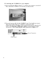
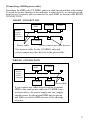
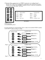
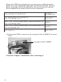
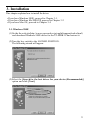
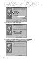
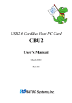
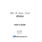
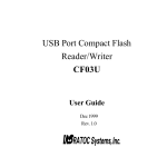
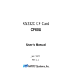
U2-MDK1U
User’s Manual
Contents
1. Introduction .................................................... 1
2. Setting .............................................................. 3
3. Installation....................................................... 9
4. Exchanging HD cases ................................... 12
5. Registration and Tech-support.................... 13
6. Specifications ................................................ 13
Jan. 2003
Rev 1.0
1. Introduction
1-1. Features
•The interface module includes RATOC's original circuit and firmware for highperformance USB2.0 to IDE conversion. It supports UDMA mode 4.
•RATOC’s original circuit and firmware enables a removable HDD.
•Allows HDD exchanging without the System shutdown or restart.
•Support ‘Big Drive’/48bit LBA.
•The HDD tray includes 80-conductors ATA133/100 cable and convenient pullout handle.
1-2. Package Confirmation
Check your package contents:
• U2-MDK1
• One lock key
• Screws to mount a HDD
• USB2.0 mother board cable
(2.54mm pitch single header 4pin --USB TypeB-M)
• User’s Manual
NOTE
1.A HDD isn’t included in the package.
2.If any of these items are missing from the retail package, contact
your supplier immediately.
1-3. System Requirements
•Windows
OS:Windows XP-SP1/2000/Me/98SE
PC with USB port
1
1-4. Restrictions
(1)A HDD power cable is required exclusively.
For more information, refer to Chapter 2-2.
(2)If you exchange a HDD, refer to Chapter 4.
(3)The following HDDs are guaranteed to work fine with the U2-MDK1U.
(Sept. in 2002).
For more information, refer to our web site:
(http://www.rexpccard.co.jp/english/)
IBM DTLA Series/IC35 Series
Maxtor DiamondMAX Series
Fireball Plus AS Series
Seagate Barracuda ATA Series
(4)Supports the following ATAPI MODE:
PIO MODE 4/DMA MODE 0-2/ULTRA DMA MODE 0-4
1-5. Caution
Just in case, you should back up important data stored in a HDD of your PC
or in a HDD used with U2-MDK1U before you use it.
RATOC assumes no liability resulting from the loss of important data.
2
2. Setting
This chapter explains how to set up U2-MDK1U. Proceed to Chapter 2-1.
2-1.Attaching a HDD to U2-MDK1U
To attach a HDD to the U2-MDK1U, follow the steps:
(1)Turn the key switch to the UNLOCKED POSITION. Then, lift handle to
release the HD case from the removable case and pull out.
Cover
Removable case
HD case
Key switch
Handle
Access LED
Power LED
(2)Slide cover off the HD case and connect power and data cable to the HDD.
Mount the HDD in the HD case with the screws provided.
(NOTE)You must set [MASTER] position at HDD jumper setting.
For a Western Digital HDD, set [SINGLE] position at HDD
jumper setting. For more information, refer to its manual.
Power cable and data cable
Screws
Handle
(3)Reinstall cover on the HD case and push the HD case back into the
removable case.
(4)Lower handle and lock the HD case with the lock key provided. If you don’t
lock it, U2-MD1U won’t work.
Next, proceed to 2-2 to attach the U2-MDK1U to your computer.
3
2-2.Attaching the U2-MDK1U to your computer
(1)After attaching the HDD at Chapter 2-1, confirm your computer is turned off.
Then, attach the U2-MDK1 to a 5 inch bay as shown below.
(2)You need a power cable for the U2-MDK1U only. You should not connect
other devices other than the U2-MDK1U to the power cable.
Connect the cable to the power connector on the rear panel as shown below.
Refer to [Connecting a HDD power cable] in the next page for more
information. After connecting the cable, proceed to Chapter 2-3.
Power Connector
USB2.0 port
4
[Connecting a HDD power cable]
Sometimes the HDD in the U2-MDK1 causes in-rush current problem at the startup.
To avoid the power shortage or the influence to other devices, we strongly recommend to use a separate power connector for each HDD as shown in the RIGHT
CONNECTION.
RIGHT CONNECTION
Internal
HDD
CD-ROM
FDD
Power
supply
unit in
computer
U2-MDK1
Power cable
Never connect any other devices
Use a power cable for the U2-MDK1 only and
never connect any other devices to the power cable
WRONG CONNECTION
Internal
HDD
U2-MDK1
Power
supply
unit in
computer
CD-ROM
FDD
Power cable
If you connect any other devices such as a internal
HDD to the same power cable the U2-MDK1 uses
as shown above, the power supply unit can’t supply
enough power for the internal HDD unit to spin up
and fails to work the HDD because of the shortage
of power.
5
2-3.Connecting the bundled USB2.0 mother board cable
NOTICE
•Connect the bundled USB2.0 cable at your own risk.RATOC assumes no
liability resulting from the breakage of a mother board or other devices,
caused by connecting the cable mistakenly.
•The bundled USB2.0 mother board cable is certified with USB2.0 logo,
but the cable doesn’t guarantee the USB 2.0 performance with a mother
board.
• Before connecting the cable, be sure to turn off your system and unplug
the power cable. To avoid the breakage with static charge or shocks,
be careful to read the user’s manual that accompanied your mother board.
Follow the steps carefully to connect the USB2.0 mother board cable.
(1)The connector at the side of a mother board comprises the following
4 kinds of connectors.
RED: VBUS(Power Supply)
White: DGreen: D+
Black: GND
6
(2)Connect these connectors to a USB2.0 connector on a mother board.
Please note USB2.0 pin assignment or pin names vary in different mother
boards, so we take as an example a mother board of which pin assignment
is recommended by Intel. See Fig.1.
1
2
3
4
5
6
7
8
9
10
Pin#1:
Pin#3:
Pin#5:
Pin#7:
Pin#9:
USB POWER
USB PUSB P+
GND
Don’t care
Pin#2:
Pin#4:
Pin#6:
Pin#8:
Pin#10:
USB POWER
USB PUSB P+
GND
NC(Don’t care)
pin names
(Fig.1)
pin assignment
recommended by Intel.
For pin assignment recommended by Intel, connect the bundled USB2.0 mother
board cable as shown in Fig.2 or Fig3.:
mother board
(Fig.2)
bundled cable
1
Red(VBUS)
3
White(D-)
5
Green(D+)
7
Black (GND)
mother board
bundled cable
2
Red(VBUS)
4
White(D-)
6
Green(D+)
8
Black (GND)
(Fig.3)
7
Please note USB2.0 pin assignment or pin names vary in different mother
boards. If your pin assignment or pin names are different from Fig1. shown in
the previous page, refer to the table below. Be sure to read user’s manual
that accompanied your mother board for more information.
Terms of pin names on a mother board
The name of
the bundled cable
VCC, USB POWER, (+)5V, POWER, etc.
Find a word indicating "Power".
RED(VBUS)
DATA- , USB- , USB Dn- (n means number), DMn(n means number), etc.
Find a word indicating "Minus".
White(D- )
DATA+, USB+, USB Dn+(n means number), DPn(n means number), etc.
Green(D+)
Find a word indicating "Plus".
GND, Ground, etc.
Black (GND)
(3)Connect the USB2.0 connector to the rear panel of the U2-MDK1U as shown
below.
rear panel of the U2-MDK1
Proceed to Chapter 3.Installation after connecting it.
8
3. Installation
This chapter explains how to install the driver.
•If you have Windows 98SE, proceed to Chapter 3-1.
•If you have Windows Me/2000/XP, proceed to Chapter 3-2.
•If you have Mac OS, proceed to Chapter 3-4.
3-1.Windows 98SE
(1)Go the the web site(http://www.rexpccard.co.jp/english/support/index.html)
and download Windows 98SE driver for the U2-MDK1U and extract it.
(2)Turn the key switch to the LOCKED POSITION.
The following wizard will appear.
(2)Select the [Search for the best driver for your device.(Recommended)]
option and click [Next].
9
(3)Select the [Specify a location] option and click [Browse]to specify the
driver.(The following screen as an example specifies the driver at the
U2MDK1U folder in C drive. The location of the driver depends on where
you downloaded the driver in your computer at step 1)
(4)The driver is found. Click [Next].
(5)Windows has finished installing the driver. Click [Finish].
Proceed to Chapter 3-3 to confirm the installation.
10
3-2.Windows Me/2000/XP
Turn the key switch to the LOCKED POSITION.
The driver will be copied automatically. Proceed to Chapter 3-3 to confirm
the installation.
3-3.Confirming the installation
Open [My Computer]. If you can find a Removable Disk icon as shown
below, the driver installation is successful.
When you double click on the Removable icon and get an error saying
the device is not ready, check the following:
1)The key switch must be in the LOCKED POSITION.
2)The HDD in the U2-Dock must be formatted.
Refer to Chapter 5 for formatting.
Proceed to Chapter 4 for how to use the U2-MDK1.
11
4. Exchanging HD cases
This chapter explains how to exchange HD cases.
To exchange HD cases, follow the steps:
(1)Open [My Computer] and
right-click on the removable
icon. The pull-down menu will
appear. Select the [Eject].
(2)Turn the key switch to the
UNLOCKED POSITION.
(The removable icon still
appears even after turning
the key switch to the
UNLOCKED POSITION.)
(3)Wait about 5 seconds until the HDD spins down completely.
Then,exchange HD cases.
(NOTE)
If you double-click on the removable icon before you turn the
key switch to the LOCKED POSITION, you will see the
following warning message. In this case, after turning the key
switch to the LOCKED POSITION, double-click on the icon.
( OS:Windows 98SE )
( OS:Windows Me/Windows 2000/XP )
(4)Turn the key switch to the LOCKED POSITION. The HDD will spin
up. After a few seconds, the Access LED (RED) will flash. You may
access to the HDD after the Access LED flashed.
12
5. Registration and Tech-support
5-1. How to Register
We highly recommend to register yourself as our customer through our on-line registration.
1. On the Internet, access our site.
(https://regist.ratocsystems.com/english/)
2. Follow on-screen instructions to register.
3. Fill out and submit the registration form.
5-2. Software Update and Support
-Software UpdateThe latest driver and application software are subject to change for improvement or bug fix.
You can download the latest version from our web site.
(http://www.ratocsystems.com/english/)
-Technical SupportYou can get a Tech support from RATOC at the following.
(Open Monday - Friday, 9:30A.M. to 5:00P.M.(PST))
RATOC Systems International,Inc. Tech support
Address: 1933 O’Toole Avenue Suite A109
SanJose, CA 95131, U.S.A.
Phone : (408)955-9400
Fax
: (408)955-9402
E-mail : [email protected]
Web
: http://www.ratocsystems.com/english/
6. Specifications
Model
Interface
Data transfer rate
Drive
Electrical: Input
Power dissipation
Size
Weight
U2-MDK1
Upstream USB2.0 480Mbps one Type B(F) port.
Downstream IDE ATA133/100/66/33/PIO4 compatible.
For a computer:480/12 Mbps
For a drive:66 MBytes
3.5 inch ATA HD(ATA 133/100/66/33), ATAPI MO, ATAPI Zip
5V/12V
5V/220mA(TPY.), 250mA(MAX), 12V/60mA(FAN)
(Excluding HDD power dissipation)
147mm(5.78in)(W) x 213mm(8.38in)(L) x 38mm(1.49in)(H)
490g(17.3oz)
13
Copyright
©2003 RATOC Systems,Inc. All rights reserved. No part of this publication may be reproduced,
store in a retrieval system, or transmitted in any form or by any means(electronic, mechanical,
photocopying, recording or otherwise) without the prior written consent of RATOC Systems,Inc.
Trademarks
-Windows is a registered trademark of Microsoft Corporation.
-Other brand and product names may be registered trademarks or trademarks of
their respective holders.
Changes
The information in this User’s Manual is furnished for information only and is subject to change
without notice. RATOC Systems,Inc. reserves the right to make changes in the product design or
product improvements without reservations and without notification to its users. RATOC
Systems,Inc. assumes no responsibility or liability for any errors or inaccuracies that may appear in
this document.
Regulatory Agency Notice
FCC Compliance Statement
This equipment has been tested and found to comply with the limits for a Class B digital device,
pursuant to Part 15 of the FCC Rules. These limits are designed to provide reasonable protection
against harmful interference in a residential installation. This equipment generates, uses and can
radiate radio frequency energy and, if not installed and used in accordance with the instructions,
may cause harmful interference to radio communications. However, there is no guarantee that
interference will not occur in a particular installation. If this equipment does cause harmful
interference to radio or television reception, which can be determined by turning the equipment
off and on, the user is encouraged to try to correct the interference by one or more of the
following measures:
(1) Reorient or relocate the receiving antenna.
(2) Increase the separation between the equipment and receiver.
(3) Connect the equipment into an outlet on a circuit different from that to which the receiver is
connected.
(4) Consult the dealer or an experienced radio/TV technician for help.
Changes or modifications not expressly approved by the party responsible for compliance may
result in this unit not complying with FCC Rules Part 15.
14