1
Basic version
Advanced version
AV Surround Receiver
Owner’s Manual
Information
NR1402
nSAFETY PRECAUTIONS
CAUTION:
TO REDUCE THE RISK OF ELECTRIC SHOCK, DO NOT REMOVE
COVER (OR BACK). NO USER-SERVICEABLE PARTS INSIDE.
REFER SERVICING TO QUALIFIED SERVICE PERSONNEL.
The exclamation point within an equilateral triangle is intended
to alert the user to the presence of important operating
and maintenance (servicing) instructions in the literature
accompanying the appliance.
WARNING:
TO REDUCE THE RISK OF FIRE OR ELECTRIC SHOCK, DO NOT
EXPOSE THIS APPLIANCE TO RAIN OR MOISTURE.
Read these instructions.
Keep these instructions.
Heed all warnings.
Follow all instructions.
Do not use this apparatus near water.
Clean only with dry cloth.
Do not block any ventilation openings.
Install in accordance with the manufacturer’s instructions.
Do not install near any heat sources such as radiators, heat registers,
stoves, or other apparatus (including amplifiers) that produce heat.
9. Protect the power cord from being walked on or pinched particularly at
plugs, convenience receptacles, and the point where they exit from the
apparatus.
10. Only use attachments/accessories specified by the manufacturer.
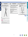
11. Use only with the cart, stand, tripod, bracket, or table
specified by the manufacturer, or sold with the apparatus.
When a cart is used, use caution when moving the cart/
apparatus combination to avoid injury from tip-over.
12. Unplug this apparatus during lightning storms or when
unused for long periods of time.
CAUTION:
To completely disconnect this product from the mains, disconnect the plug
from the wall socket outlet.
The mains plug is used to completely interrupt the power supply to the unit
and must be within easy access by the user.
I
marantz Europe
A division of D&M Europe B.V.
Beemdstraat 11, 5653 MA Eindhoven,
The Netherlands
A NOTE ABOUT RECYCLING:
This product’s packaging materials are recyclable and can
be reused. Please dispose of any materials in accordance
with the local recycling regulations.
When discarding the unit, comply with local rules or
regulations.
Batteries should never be thrown away or incinerated
but disposed of in accordance with the local regulations
concerning battery disposal.
This product and the supplied accessories, excluding the
batteries, constitute the applicable product according to
the WEEE directive.
Information
13.Refer all servicing to qualified service personnel.
Servicing is required when the apparatus has been damaged in any way,
such as power-supply cord or plug is damaged, liquid has been spilled or
objects have fallen into the apparatus, the apparatus has been exposed to
rain or moisture, does not operate normally, or has been dropped.
14.Batteries shall not be exposed to excessive heat such as sunshine, fire or
the like.
We declare under our sole responsibility that this product, to which this
declaration relates, is in conformity with the following standards:
EN60065, EN55013, EN55020, EN61000-3-2 and EN61000-3-3.
Following the provisions of Low Voltage Directive 2006/95/EC and EMC
Directive 2004/108/EC, the EC regulation 1275/2008 and its frame work
Directive 2009/125/EC for Energy-related Products (ErP).
Advanced version
The lightning flash with arrowhead symbol, within an equilateral
triangle, is intended to alert the user to the presence of
uninsulated “dangerous voltage” within the product’s enclosure
that may be of sufficient magnitude to constitute a risk of
electric shock to persons.
1.
2.
3.
4.
5.
6.
7.
8.
• DECLARATION OF CONFORMITY
Basic version
CAUTION
RISK OF ELECTRIC SHOCK
DO NOT OPEN
IMPORTANT SAFETY
INSTRUCTIONS
nCAUTIONS ON INSTALLATION
nNOTES ON USE
z
z
z
z
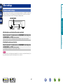
Wall
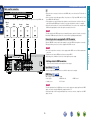
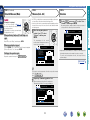
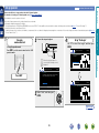
zzFor proper heat dispersal, do not install this unit in a confined
space, such as a bookcase or similar enclosure.
•More than 0.3 m is recommended.
•Do not place any other equipment on this unit.
Advanced version
•Avoid high temperatures.
Allow for sufficient heat dispersion when installed in a rack.
•Handle the power cord carefully.
Hold the plug when unplugging the cord.
•Keep the unit free from moisture, water, and dust.
•Unplug the power cord when not using the unit for long periods of time.
•Do not obstruct the ventilation holes.
•Do not let foreign objects into the unit.
•Do not let insecticides, benzene, and thinner come in contact with the unit.
•Never disassemble or modify the unit in any way.
•Ventilation should not be impeded by covering the ventilation openings
with items, such as newspapers, tablecloths or curtains.
•Naked flame sources such as lighted candles should not be placed on
the unit.
•Observe and follow local regulations regarding battery disposal.
•Do not expose the unit to dripping or splashing fluids.
•Do not place objects filled with liquids, such as vases, on the unit.
•Do not handle the mains cord with wet hands.
•When the switch is in the OFF (STANDBY) position, the equipment is not
completely switched off from MAINS.
•The equipment shall be installed near the power supply so that the power
supply is easily accessible.
Basic version
WARNINGS
Information
II
Basic version
Getting started
Thank you for purchasing this marantz product. To ensure proper operation, please read this owner’s manual carefully before using the product.
After reading them, be sure to keep them for future reference.
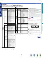
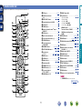
Contents
Getting started···············································································1
Accessories···················································································1
Features·························································································2
Cautions on handling·····································································2
Information··············································································73
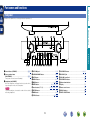
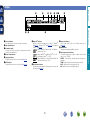
Part names and functions···························································74
Front panel···················································································74
Display·························································································75
Rear panel····················································································76
Remote control unit·····································································77
Other information········································································79
Trademark information·································································79
Surround······················································································80
Relationship between video signals and monitor output·············84
Explanation of terms····································································85
Troubleshooting···········································································87
Resetting the microprocessor·····················································89
Specifications···············································································90
1
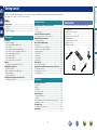
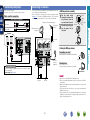
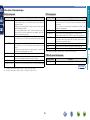
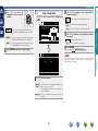
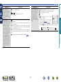
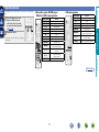
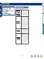
Accessories
Check that the following parts are supplied with the product.
qGetting Started......................................................................... 1
wCD-ROM (Owner’s manual)..................................................... 1
ePower cord............................................................................... 1
rRemote control unit (RC013SR)............................................... 1
tR03/AAA batteries.................................................................... 2
ySetup microphone (ACM1H).................................................... 1
uAM loop antenna...................................................................... 1
iFM indoor antenna................................................................... 1
e
r
u
y
i
Information
Connections····················································································4
Important information····································································4
Connecting an HDMI-compatible device·······································5
Connecting a TV············································································7
Connecting a Blu-ray Disc player/DVD player································7
Connecting a set-top box (Satellite tuner/Cable TV)······················8
Connecting a portable audio player················································8
Connecting a CD player·································································9
Connecting an antenna··································································9
Connecting a wireless receiver (RX101)······································10
Settings·························································································11
Set up speakers (Audyssey® Auto Setup)··································11
Playback (Basic operation)··························································18
Important information··································································18
Playing a Blu-ray Disc player/DVD player·····································19
Playing a CD player······································································19
Tuning in radio stations································································20
Selecting a listening mode (Surround mode)···························24
Selecting a listening mode··························································24
Speaker installation/connection (Advanced) ···························29
Install···························································································29
Connect·······················································································31
Set up speakers···········································································35
Connections (Advanced connection)·········································37
Connecting the remote control connectors·································37
Playback (Advanced operation)··················································38
Convenient functions···································································38
How to make detailed settings···················································43
Menu map···················································································43
Examples of menu screen displays·············································44
Examples of menu and front display···········································45
Inputting characters ····································································46
Audio Adjust················································································48
Information··················································································53
System Setup··············································································54
Input Setup··················································································62
Other settings···············································································67
Remote control settings······························································67
Operating the connected devices by remote control unit·······68
Operating AV devices··································································68
Registering preset codes·····························································69
Operating devices········································································71
Advanced version
Basic version·············································································3
Advanced version ·······························································28
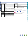
Features
The unit is equipped with a power amplifier that reproduces highfidelity sound in surround mode with equal quality and power for all
channels, true to the original sound.
The power amplifier circuit adopts a discrete-circuit configuration
that achieves high-quality surround sound reproduction.
The unit is equipped with a decoder which supports high-quality
digital audio format for Blu-ray Disc players such as Dolby TrueHD,
DTS-HD Master Audio, etc.
M-XPort (marantz-eXtension Port) (vpage 10)
This unit is equipped with the M-XPort, a marantz original innovation
that provides outstanding expandability. You can connect the
Wireless Receiver RX101 (sold separately) to this port.
First select the language when prompted. Then simply follow the
instructions displayed on the TV screen to set up the speakers, etc.
Easy to use, Graphical User Interface
•Before turning the power on
Check once again that all connections are correct and that there are
no problems with the connection cables.
•Power is supplied to some of the circuitry even when the unit is
set to the standby mode. When going on vacation or leaving home
for long periods of time, be sure to unplug the power cord from the
power outlet.
•About condensation
If there is a major difference in temperature between the inside of
the unit and the surroundings, condensation (dew) may form on
the operating parts inside the unit, causing the unit not to operate
properly.
If this happens, let the unit sit for an hour or two with the power
turned off and wait until there is little difference in temperature
before using the unit.
•Cautions on using mobile phones
Using a mobile phone near this unit may result in noise. If that
occurs, move the mobile phone away from this unit when it is in use.
This unit is equipped with an easy to see “Graphical User Interface”
that uses menu displays and levels. The use of level displays
increases operability of the this unit.
Supports HDMI 1.4a with 3D, ARC, Deep Color,
“x.v.Color”, Auto Lip Sync and HDMI control
function (vpage 5)
•About care
•Wipe the cabinet and control panel clean with a soft cloth.
•Follow the instructions when using a chemical cleaner.
•Benzene, paint thinner or other organic solvents as well as
insecticide may cause material changes and discoloration if brought
into contact with the unit, and should therefore not be used.
This unit can output 3D video signals input from a Blu-ray Disc
player to a TV that supports a 3D system. This unit also supports
the ARC (Audio Return Channel) function, which reproduces TV
sound with this unit via an HDMI cable used for connecting the
unit and a TVz.
zzThe TV should support the ARC function.
4-HDMI inputs and 1-output
The unit is equipped with 4 HDMI input connectors for connecting
devices with HDMI connectors, such as a Blu-ray Disc player,
game machine, HD video camera, etc.
2
Information
•Moving the unit
Turn off the power and unplug the power cord from the power
outlet. Next, disconnect the connection cables to other system units
before moving the unit.
Advanced version
Setup wizard, providing easy-to-follow setup
instructions
High definition audio support
Basic version
Fully discrete, identical quality and power for all
5 channels (50 W x 5ch, 8 Ω)
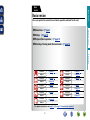
Cautions on handling
Basic version
Here, we explain the connections and basic operation methods for this unit.
Advanced version
F Connections vpage 4
Basic version
Basic
version
F Settings vpage 11
F Playback (Basic operation) vpage 18
F Selecting a listening mode (Surround mode) vpage 24
Information
vpage 6, 7
Connection
–
Playback
vpage 6, 7
Connection
vpage 19
Playback
vpage 8
Connection
–
Playback
vpage 6
Connection
–
Playback
Connection
Playback
Connection
Playback
Connection
Playback
Connection
Playback
vpage 10
Connection
–
Playback
For speaker connections, see page 31, C page 6 “Connecting the speakers”.
3
vpage 6, 7
vpage 19
vpage 6, 8
–
vpage 9
vpage 19
vpage 9
vpage 20
Basic version
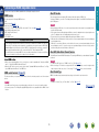
Connections
Important information
•Make connections as follows before using this unit. Select an appropriate connection type
according to the devices to be connected.
•You may need to make some settings on this unit depending on the connection method. Refer to
each description for more information.
•Select the cables (sold separately) according to the devices being connected.
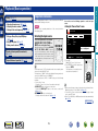
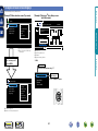
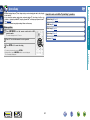
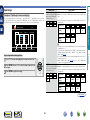
Examples of screen display
•Menu screen
When the volume is adjusted.
Menu
•Do not plug in the power cord until all connections have been completed. (When the Setup wizard is
running, follow the instructions in the Setup wizard screen for making connections.)
•When running the Setup wizard, turn off the power supply of connected devices.
•When making connections, also refer to the operating instructions of the other devices being connected.
•Be sure to connect the left and right channels properly (left with left, right with right).
•Do not bundle power cords together with connection cables. Doing so can result in noise.
Audio Adjust
Information
Setup Wizard
System Setup
Input Setup
[Auto]
SOURCE :BD
MODE :STEREO
Master Volume
-55.5dB
Status display: The operating status appears briefly on the screen
when the input source is switched or the volume is
changed.
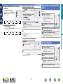
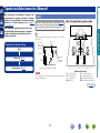
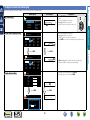
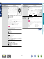
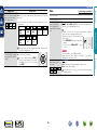
Relationship between video signals and monitor output
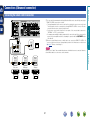
GFlow of video signalsH
NOTE
•If you operate the menu while playing back 3D video content or computer’s resolution (e.g. VGA), the
playback video is replaced by the menu screen. The playback video is not displayed behind the menu
screen.
•This unit does not show the status display while playing back 3D video content or computer’s resolution
(e.g. VGA).
•The menu screen and status display are displayed when this unit and a TV are connected by HDMI.
Furthermore, the menu screen and status display are not displayed when this unit and a TV are connected
by VIDEO and COMPONENT VIDEO.
Monitor (TV)
This unit
Output
Input
(IN)
Output
(MONITOR OUT)
HDMI connector
HDMI connector
HDMI
connector
HDMI connector
Component video
connectors
Component video
connectors
Component video
connectors
Component video
connectors
Video connector
Video connector
Video connector
Video connector
Input
•Resolutions of HDMI-compatible TVs can be checked at “Monitor Info.” (vpage 53).
•HDMI signals cannot be converted into analog signals (vpage 84).
•Analog signals cannot be converted into HDMI signals (vpage 84).
4
Information
Video device
Surr.Parameter
Tone
AudysseySettings
Manual EQ
M-DAX
Audio Delay
Advanced version
NOTE
•Status display screen
When the input source is
switched.
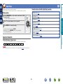
Connecting an HDMI-compatible device
About 3D function
HDMI function
This unit supports input and output of 3D (3 dimensional) video signals of HDMI 1.4a.
To play back 3D video, you need a TV and player that provide support for the HDMI 1.4a 3D function and
a pair of 3D glasses.
This unit supports the following HDMI functions:
•3D
•Deep Color (vpage 85)
•Auto Lip Sync (vpage 58, 85)
•“x.v.Color”, sYCC601 color, Adobe RGB color, Adobe YCC601 color (vpage 85, 86)
•High definition digital audio format
•ARC (Audio Return Channel)
•Content Type
•CEC (HDMI control)
Basic version
You can connect up to five HDMI-compatible devices (4-inputs/1-output) to the unit.
NOTE
Copyright protection system
In order to play back digital video and audio such as BD-Video or DVD-Video via HDMI connection, both
this unit and TV or the player need to support the copyright protection system known as HDCP (Highbandwidth Digital Content Protection System). HDCP is copyright protection technology comprised of
data encryption and authentication of the connected AV devices. This unit supports HDCP.
•If a device that does not support HDCP is connected, video and audio are not output correctly. Read
the owner’s manual of your television or player for more information.
Advanced version
•When playing back 3D video, refer to the instructions provided in the manual of your playback device
together with this manual.
•If you operate the menu while playing back 3D video content, the playback video is replaced by the menu
screen. The playback video is not displayed behind the menu screen.
•This unit does not show the status display while playing back 3D video content.
•If 3D video with no 3D information is input, the menu screen and status display on this unit are displayed
over the playback video.
•If 2D video is converted to 3D video on the television, the menu screen and status display on this unit
are not displayed correctly. To view the menu screen and status display on this unit correctly, turn the
television setting that converts 2D video to 3D video off.
About ARC (Audio Return Channel) function
The Audio Return Channel in HDMI 1.4a enables a TV, via a single HDMI cable, to send audio data “upstream”
to this unit.
NOTE
•To enable the ARC function, set “HDMI Control” to “ON” (vpage 58).
•When connecting a TV that does not support the ARC function, a separate connection using an audio
cable is required. In this case, refer to “Connecting a TV” (vpage 7) for the connection method.
About Content Type
HDMI control function (vpage 38)
HDMI 1.4a enables simple, automated picture setting selection with no user intervention.
This function allows you to operate external devices from the unit and operate the unit from external
devices.
NOTE
NOTE
To enable the Content Type, set “Video Mode” to “Auto” (vpage 65).
•The HDMI control function may not work depending on the device it is connected to and its settings.
•You cannot operate a TV or Blu-ray Disc player/DVD player that is not compatible with the HDMI control
function.
vSee overleaf
5
Information
About HDMI cables
•When a device supporting Deep Color is connected, use a cable compatible with “High Speed HDMI
cable” or “High Speed HDMI cable with Ethernet”.
•When the ARC function is used, connect a device with a ”Standard HDMI cable with Ethernet” or “High
Speed HDMI cable with Ethernet” for HDMI 1.4a.
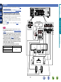
Connecting an HDMI-compatible device
Audio and video cable (sold separately)
•When this unit is connected to other devices with HDMI cables, connect this unit and TV also with an
HDMI cable.
•When connecting a device that supports Deep Color, please use a “High Speed HDMI cable” or “High
Speed HDMI cable with Ethernet”.
•Video signals are not output if the input video signals do not match the monitor’s resolution. In this case,
switch the Blu-ray Disc/DVD player’s resolution to a resolution with which the monitor is compatible.
•When this unit and monitor are connected with an HDMI cable, if the monitor is not compatible with
HDMI audio signal playback, only the video signals are output to the monitor.
HDMI cable
•This interface allows transfer of digital video signals and digital audio signals over a single HDMI cable.
DVD
player
Set-top
box
Game
console
TV
HDMI
OUT
HDMI
OUT
HDMI
OUT
HDMI
OUT
HDMI
IN
NOTE
The audio signal from the HDMI output connector (sampling frequency, number of channels, etc.) may be
limited by the HDMI audio specifications of the connected device regarding permissible inputs.
Connecting to a device equipped with a DVI-D connector
When an HDMI/DVI conversion cable (sold separately) is used, the HDMI video signals are converted to
DVI signals, allowing connection to a device equipped with a DVI-D connector.
Advanced version
Blu-ray
Disc
player
Basic version
Cables used for connections
NOTE
nnSettings related to HDMI connections
Set as necessary. For details, see the respective reference pages.
Input Assign (vpage 64)
Set this to change the HDMI input connector to which the input source is assigned.
HDMI Setup (vpage 58)
Make settings for HDMI video/audio output.
•Auto Lip Sync
•HDMI Audio Out
•Standby Source
•P.Off Control
•HDMI Control
NOTE
The audio signal input from the HDMI input connector can be output as an output signal from the HDMI
output connector by setting the HDMI audio output destination to TV.
Audio signals input via the Analog/Coaxial/Optical input connectors cannot be output from the HDMI
output connector.
6
Information
•No sound is output when connected to a device equipped with a DVI-D connector. Make separate audio
connections.
•Signals cannot be output to DVI-D devices that do not support HDCP.
•Depending on the combination of devices, the video signals may not be output.
Connecting a TV
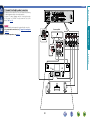
Connecting a Blu-ray Disc player/DVD player
•You can enjoy video and audio from a Blu-ray Disc or DVD.
•Select the connector to use and connect the device.
•For instructions on HDMI connections, see “Connecting an HDMI-compatible device” (vpage 5).
Cables used for connections
To listen to TV audio through this device, use the optical digital connection.
Video cable (sold separately)
NOTE
Video cable
Component video
cable
Cables used for connections
Audio cable
Video cable
Y
PB
PB
PB
PB
PR
PR
PR
PR
L
L
R
R
Coaxial digital cable
Blu-ray Disc player
DVD player
COMPONENT VIDEO
OUT
Y
PB PR
VIDEO
VIDEO
IN
VIDEO
OUT
AUDIO
AUDIO
COAXIAL
OUT
AUDIO
OUT
L
R
L
R
L
R
VIDEO
VIDEO
OUT
COMPONENT VIDEO
OUT
Y
PB PR
in Set as Necessary
in Set as Necessary
Set this to change the digital input connector or component video input connector to which the input
source is assigned.
“Input Assign” (vpage 64)
At the time of purchase, the OPTICAL input connector is assigned to “CD”. To use the OPTICAL input
connector for the TV audio input, change the settings of “Input Assign” (vpage 64) in the menu.
When you want to play back HD Audio (Dolby TrueHD, DTS-HD, Dolby Digital Plus, DTS Express) and Multichannel PCM with this unit, use an HDMI connection (vpage 5 “Connecting an HDMI-compatible
device”).
7
Information
VIDEO
TV
COMPONENT VIDEO
IN
Y
P B PR
Y
Audio cable (sold separately)
Video cable (sold separately)
Component video
cable
Y
Advanced version
The optical connection is not required when a TV compatible with the ARC function (Audio Return Channel
HDMI 1.4a standard function) is connected to this unit via an HDMI connection.
For details, see “About ARC (Audio Return Channel) function” (vpage 5) or refer to the instruction
manual for your TV.
Y
Basic version
•Select the connector to use and connect the device.
•For instructions on HDMI connections, see “Connecting an HDMI-compatible device” (vpage 5).
Connecting a set-top box (Satellite tuner/Cable TV)
Connecting a portable audio player
If a portable player is connected via the AUX INPUT jack of the unit, music from the portable player can
be played.
Cables used for connections
Cables used for connections
Audio cable (sold separately)
Video cable (sold separately)
Stereo mini
plug cable
Video cable
Audio cable (sold separately)
L
R
R
Portable
audio player
AUDIO
AUDIO
OUT
Satellite tuner/
Cable TV
VIDEO
AUDIO
VIDEO
OUT
AUDIO
OUT
L
R
R
L
R
Information
L
Advanced version
Audio cable
L
Basic version
•You can watch satellite or cable TV.
•Select the connector to use and connect the device.
•For instructions on HDMI connections, see “Connecting an HDMI-compatible device” (vpage 5).
You can enjoy listening to music by connecting a portable audio player via the AUX INPUT jack. In this case,
set the input source to “AUX”.
in Set as Necessary
Set this to change the digital input connector or component video input connector to which the input
source is assigned.
“Input Assign” (vpage 64)
8
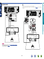
Connecting a CD player
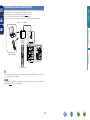
Connecting an antenna
•Connect the FM antenna or AM loop antenna supplied with the unit
to enjoy listening to radio broadcasts.
•After connecting the antenna and receiving a broadcast signal
(vpage 20 “Listening to FM/AM broadcasts”), fix the antenna
with tape in a position where the noise level becomes minimal.
Cables used for connections
Audio cable (sold separately)
Audio cable
L
L
R
R
Direction of broadcasting station
FM outdoor
antenna
AM loop antenna
(supplied)
the stand section
1 Put
through the bottom of the
loop antenna from the
rear and bend it forward.
the projecting part
2 Insert
into the square hole in
Stand
Square
hole
Loop
antenna
Projecting
part
the stand.
Advanced version
Optical cable
nnAM loop antenna assembly
CD player
AUDIO
OPTICAL
OUT
AUDIO
OUT
L
R
R
L
R
w
e
75 Ω coaxial
cable
nnUsing the AM loop antenna
Suspending on a wall
Suspend directly on a wall without assembling.
Black
White
FM indoor
antenna
(supplied)
in Set as Necessary
Nail, tack, etc.
Standing alone
Use the procedure shown above to assemble.
Set this to change the digital input connector to which the input
source is assigned.
“Input Assign” (vpage 64)
NOTE
AM outdoor
antenna
Ground
9
•Do not connect two FM antennas simultaneously.
•Even if an external AM antenna is used, do not disconnect the AM
loop antenna.
•Make sure the AM loop antenna lead terminals do not touch metal
parts of the panel.
•If the signal has noise interference, connect the ground terminal
(GND) to reduce noise.
•If you are unable to receive a good broadcast signal, we recommend
installing an outdoor antenna. For details, inquire at the retail store
where you purchased the unit.
Information
L
q
Basic version
•You can enjoy CD sound.
•Select the connector to use and connect the device.
Connecting a wireless receiver (RX101)
Basic version
By connecting a wireless receiver RX101 (sold separately) to this unit, you can receive and playback audio
signals from other devices using the Bluetooth Communication Function.
•Use a Bluetooth device that is A2DP compatible (vpage 85 “A2DP”).
•You can also use wireless receiver RX101 as an external IR receiver.
•For instructions on the wireless receiver settings, refer to the RX101’s operating instructions.
Wireless receiver RX101
Advanced version
Information
Bluetooth device
(A2DP Compatibility)
Remote control unit
You can enjoy listening to music by connecting a wireless receiver via the M-XPort input connector. In this
case, set the input source to “M-XPort”.
NOTE
To use wireless receiver RX101 as external IR receiver, set the remote sensor function of this unit to
disable (vpage 67 “Remote control settings”).
10
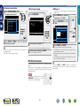
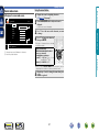
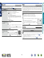
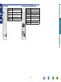
Here, we explain “Audyssey® Auto Setup”, which allows you to
automatically make the optimal settings for your speakers.
nn Set up speakers (Audyssey® Auto Setup)
(vpage 11)
Selecting a listening mode (Surround mode)
(vpage 24)
Playback (Advanced operation) (vpage 38)
Set up speakers (Audyssey® Auto Setup)
The acoustic characteristics of the connected speakers and
listening room are measured and the optimum settings are made
automatically. This is called “Audyssey® Auto Setup”.
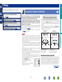
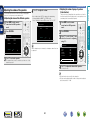
To perform measurement, place the setup microphone in
multiple locations all around the listening area. For best results,
we recommend you measure in six positions, as shown in the
illustration (up to six positions).
•When performing Audyssey® Auto Setup, Audyssey MultEQ®/
Audyssey Dynamic EQ®/Audyssey Dynamic Volume® functions
become active (vpage 50, 51).
•To set up the speakers manually, use “Speaker Setup”
(vpage 55) on the menu.
About setup microphone placement
•Measurements are performed by placing the setup microphone
successively at multiple positions throughout the entire listening
area, as shown in GExample qH. For best results, we recommend
you measure in six positions, as shown in the illustration (up to six
positions).
•Even if the listening environment is small as shown in GExample wH,
measuring at multiple points throughout the listening environment
results in more effective correction.
NOTE
GExample wH
FL SW C
FR
( : Measuring positions)
SL
*M
FL Front speaker (L)
FR Front speaker (R)
C Center speaker
FR
( : Measuring positions)
SR
SL
*M
Information
•Make the room as quiet as possible. Background noise can disrupt
the room measurements. Close windows, silence cell phones,
televisions, radios, air conditioners, fluorescent lights, home
appliances, light dimmers, or other devices as measurements may
be affected by these sounds.
•Cell phones should be placed away from all audio electronics during
the measurement process as Radio Frequency Interference (RFI)
may cause measurement disruptions (even if the cell phone is not
in use).
•Do not unplug the setup microphone from the main unit until
Audyssey® Auto Setup is completed.
•Do not stand between the speakers and setup microphone or allow
obstacles in the path while the measurements are being made. This
will cause inaccurate readings.
•Loud test sounds may be played during Audyssey® Auto setup. This
is part of normal operation. If there is background noise in room,
these test signals will increase in volume.
•Operating VOLUME +, – during
the measurements will cancel the
measurements.
•Measurement cannot be performed when
headphones are connected.
GExample qH
FL SW C
SR
SW Subwoofer
SL Surround speaker (L)
SR Surround speaker (R)
About the main listening position (*M)
The main listening position is the position where listeners would
normally sit or where one would normally sit alone within the listening
environment. Before starting Audyssey® Auto Setup, place the setup
microphone in the main listening position. Audyssey MultEQ® uses
the measurements from this position to calculate speaker distance,
level, polarity, and the optimum crossover value for the subwoofer.
vSee overleaf
11
Advanced version
Playback (Basic operation) (vpage 18)
Basic version
Settings
Set up speakers (Audyssey® Auto Setup)
Set up the microphone
Mount the setup microphone on a tripod or stand
and place it in the main listening position.
When placing the setup microphone, adjust the height of the
sound receptor to the level of the listener’s ear.
Sound receptor
Set up the subwoofer
If using a subwoofer capable of the following
adjustments, set up the subwoofer as shown below.
nn When using a subwoofer with a direct mode
3
Set up the remote control unit
nn Set up the operation mode
Press AMP to set the remote control unit to AMPoperation mode.
Set the direct mode to “On” and disable the volume adjustment
and crossover frequency setting.
nn When using a subwoofer without a direct mode
Make the following settings:
•Volume : “12 o’clock position”
•Crossover frequency : “Maximum/Highest Frequency”
•Low pass filter : “Off”
•Standby mode : “Off”
Advanced version
Setup
microphone
2
Basic version
1
Press AMP
vSee overleaf
Information
If you do not have a tripod or stand, set up the microphone on, for
example, a seat without a back.
NOTE
•Do not hold the setup microphone in your hand during
measurements.
•Avoid placing the setup microphone close to a seat back or wall as
sound reflections may give inaccurate results.
12
Set up speakers (Audyssey® Auto Setup)
Detect & Measure (Main)
Preparation
4
Connect the setup microphone to the SETUP MIC
jack of this unit.
6
Use ui to select “Auto Setup Start” and then press
ENTER.
Audyssey Auto Setup
MultEQ
When the setup microphone is
connected, the following screen is
displayed.
MultEQ
Audyssey Auto Setup
Preparation
Next
[ENTER] Enter
5
When measuring begins, a test tone is output from each
speaker.
Pre Assign
Channel Select
•Measurement requires several minutes.
Auto Setup Start
[ENTER] Enter
[RETURN] Cancel
Here, we explain setup using the example of 5.1-channel speaker
playback.
For settings other than 5.1-channel surround, select “Pre Assign”
and perform step 4 to 5 of “Set up “Pre Assign”” (vpage 35).
If unused channels are set with “Channel Select”, measuring time
can be shortened. For setting, perform steps 7 to 11 of “Set up
“Channel Select”” (vpage 36).
8 The detected speakers are displayed.
•The illustration below shows an example of when the front
speakers, center speaker, subwoofer, and surround speakers have
been detected.
Audyssey Auto Setup
Detect Check
Front
Center
Subwoofer
Surround
S.Back
[RETURN] Cancel
Retry
Next
Select “Next” and then press
ENTER.
MultEQ
Yes
Yes
Yes
Yes
No
Measure
[ENTER] Enter
[RETURN] Cancel
NOTE
If a connected speaker is not displayed, the speaker may not be
connected correctly. Check the speaker connection.
ui to select “Next → Measure” and then press
9 Use
ENTER.
vSee overleaf
13
Information
Connect the speakers and place them according
to the recommendations in the manual.
7 Select “Measure” and then press ENTER.
Advanced version
Preparation
Set the following items
if necessary.
•In STEP 2, you will perform measurements at the main listening
position.
•This step automatically checks the speaker configuration and speaker
size, and calculates the channel level, distance, and crossover
frequency.
It also corrects distortion in the listening area.
Basic version
STEP 2
STEP 1
Set up speakers (Audyssey® Auto Setup)
Detect & Measure (Main)
Calculate
Measure (2nd – 6th)
•In STEP 3, you will perform measurements at multiple positions (two
to six positions) other than the main listening position.
•Just one position can be measured but measuring multiple positions
increases the accuracy of the correction of acoustic distortion within
the listening area.
NOTE
When performing Audyssey® Auto Setup over
again
Press ui to select “Retry”, and then press ENTER.
When measuring has stopped
qPress RETURN, to the “Cancel Auto Setup?” prompt is displayed.
wPress o to select “Yes”, then press ENTER.
.
Audyssey Auto Setup
The measurement of the second
position starts. Measurements can be
made in up to six positions.
MultEQ
•Analysis takes several minutes to complete. The time required for
this analysis depends on the number of speakers connected.
The more connected speakers there are, the longer it takes to
perform analysis.
Measure
vSee overleaf
Calculate
[ENTER] Enter
[RETURN] Cancel
If you want to omit measurements from the next position onward,
select “Next
Calculate”.
(Go to STEP4 Calculate
)
11 Repeat step 10, measuring positions 3 to 6.
When measurement of position 6 is completed, a
“Measurements finished.” message is displayed.
Audyssey Auto Setup
MultEQ
Measure (Finish)
Measurements finished.
Retry
Next
MultEQ
0%
Measure (2nd)
Please place the
microphone at ear
height at 2nd
listening position.
Next
Measuring results are analyzed, and the frequency response of
each speaker in the listening room is determined.
Calculate
Now calculating
Please wait
“Measure”, and then press
ENTER.
Audyssey Auto Setup
STEP 3
Calculate
[ENTER] Enter
14
[RETURN] Cancel
Information
Setting up the speakers again
the setup microphone to
10 Move
position 2, use ui to select
On the
screen, use ui to select “Next →
12 Calculate”,
and then press ENTER.
Advanced version
If “Caution!” is displayed:
Go to “Error messages” (vpage 16),
check any related items, and perform the
necessary procedures.
If the problem is resolved, return and restart
“Audyssey® Auto Setup”.
Repeat the operation from step 4 of STEP 1 Preparation
STEP 4
STEP 3
Basic version
STEP 2 (Continued)
Set up speakers (Audyssey® Auto Setup)
STEP 6
Check
Finish
Store
15 Select “Store” and then press ENTER.
ui to select the item you
13 Use
want to check, and then press
Save the measurement results.
ENTER.
Audyssey Auto Setup
MultEQ
Audyssey Auto Setup
Check
Check processing resuit.
To proceed, press
“Next”.
MultEQ
Finish
Storing complete.
Auto Setup is now finished.
Please unplug microphone.
Store
[ENTER] Enter
Sp.Config. Check
Distance Check
Ch.Level Check
Crossover Check
Next
Audyssey Auto Setup
MultEQ
Turn on Dynamic Volume?
[RETURN] Cancel
Yes
No
Advanced version
Store
Press “Store” to
store calculation
result.
the setup microphone from the unit’s SETUP
16 Unplug
MIC jack.
®
17 Set Audyssey Dynamic Volume .
Basic version
STEP 5
[ENTER] Exit
Store
[ENTER] Enter
[RETURN] Cancel
Store
Now storing
Please wait
ui to select “Next → Store” and then press
14 Use
ENTER.
NOTE
•If the result differs from the actual connection status, or if “Caution!”
is displayed, see “Error messages” (vpage 16). Then carry out
Audyssey® Auto Setup again.
•If you change speaker positions or orientation, perform Audyssey®
Auto Setup again to find the optimal equalizer settings.
MultEQ
•This feature adjusts the output volume to the optimal level while
constantly monitoring the level of the audio input to the unit.
Optimal volume control is performed automatically without any
loss in the dynamism and clarity of the sound when, for example,
the volume suddenly increases for commercials shown during
television programs.
nn When turning Dynamic Volume® on
0%
•Use u to select “Yes”, and then press ENTER.
The unit automatically enters “Medium” mode.
•Saving the results requires about 10 seconds.
•If the measuring results are not to be saved, press RETURN. A
message “Cancel Auto Setup?” will be displayed. Press o then
select “Yes”. All the measured Audyssey® Auto Setup data will
be erased.
•During saving of measurements results, “Now storing Please
wait” is displayed. When saving is completed, “Storing complete.
Auto Setup is now finished.” is displayed.
NOTE
During saving of measurement results, be sure not to turn off the
power.
15
nn When turning Dynamic Volume® off
•Use i to select “No”, and then press ENTER.
NOTE
After performing Audyssey® Auto Setup, do not change the speaker
connections or subwoofer volume. In event of a change, perform
Audyssey® Auto Setup again.
Information
Audyssey Auto Setup
•Subwoofers may measure a greater reported distance than
the actual distance due to added electrical delay common in
subwoofers.
•If you want to check another item, press RETURN.
Set up speakers (Audyssey® Auto Setup)
NOTE
•An error message is displayed if Audyssey® Auto Setup could not be completed due to speaker placement, the measurement environment, etc. If this happens, check the relevant items, be sure to take the necessary
measures, then perform Audyssey® Auto Setup over again.
•If the result still differs from the actual connection status after remeasurement or the error message still appears, it is possible that the speakers are not connected properly. Turn this unit off, check the speaker
connections and repeat the measurement process from the beginning.
•Be sure to turn off the power before checking speaker connections.
MultEQ
Audyssey Auto Setup
Caution!
Microphone or Speaker is none
Measures
•The connected setup microphone is broken, or a device other than the
supplied setup microphone is connected.
•Not all speakers could be detected.
•The front L speaker was not properly detected.
•Connect the included setup microphone to the SETUP MIC jack of this unit.
•There is too much noise in the room for accurate measurements to be
made.
•Speaker or subwoofer sound is too low for accurate measurements to be
made.
•Either turn off any device generating noise or move it away.
•Perform again when the surroundings are quieter.
•Check the speaker installation and the direction in which the speakers are
facing.
•Adjust the subwoofer’s volume.
•The displayed speaker could not be detected.
(The screen on the left indicates that the front right speaker cannot be
detected.)
•Check the connections of the displayed speaker.
•The displayed speaker is connected with the polarity reversed.
(The screen on the left indicates that the polarity phases of the front right
speakers are reversed.)
•Check the polarity of the displayed speaker.
•For some speakers, this error message may be
displayed even if the speaker is properly connected.
If you are sure the connection is correct, press ui
to select “Skip”, then press ENTER.
•Check the speaker connections.
Retry
Audyssey Auto Setup
[
] Cancel
MultEQ
Caution!
Ambient noise is too high or level is too low
Retry
Audyssey Auto Setup
[
] Cancel
[
] Cancel
MultEQ
Caution! Speaker:None
Front R
Retry
MultEQ
Audyssey Auto Setup
Caution! Speaker:Phase
Front R
Skip
Retry
[
] Cancel
16
Information
Error details
Advanced version
Examples
Basic version
Error messages
Set up speakers (Audyssey® Auto Setup)
2 Use ui to select the item you want to check, then press ENTER or p.
This function enables you to check the measurement results and equalizer characteristics after Audyssey®
Auto Setup.
Measurement results for each speaker are displayed.
Sp. Config. Check
1 Use ui to select “Parameter Check” and then press ENTER.
Auto Setup
Sp. Config. Check
Distance Check
Ch. Level Check
Crossover Check
EQ Check
Distance Check
Check the distance.
Ch. Level Check
Check the channel level.
Crossover Check
Check the crossover frequency.
EQ Check
Check the equalizer.
•If “EQ Check” is selected, press ui to select equalizing curve (“Audyssey” or “Audyssey Flat”) to
be checked.
Use o p to switch the display between the different speakers.
3 Press RETURN.
The confirmation screen reappears. Repeat step 2.
Advanced version
Auto Setup
Parameter Check
Check the speaker configuration.
Basic version
Parameter Check
Retrieving Audyssey® Auto Setup settings
Parameter Check
Sp. Config. Check
Distance Check
Ch. Level Check
Crossover Check
EQ Check
Restore
17
Information
If you set “Restore” to “Yes”, you can return to Audyssey® Auto Setup measurement result (value
calculated at the start by MultEQ®) even when you have changed each setting manually.
Important information
Settings (vpage 11)
nn Selecting the input source (vpage 18)
nn Adjusting the master volume (vpage 19)
nn Turning off the sound temporarily (vpage 19)
Selecting a listening mode (Surround mode)
(vpage 24)
Source Select
Selecting the input source
Player
BD
DVD
CD
M-XPort
Press the input source select button
(BD, DVD, SAT, TV, CD, TUNER or
M-XP) twice to be played back.
When an input source select button (BD, DVD,
SAT, TV, CD, TUNER or M-XP) is pressed
once, the unit switches to device selected
by the operating mode of the remote control.
If the input source select button is then
pressed again twice, the input source for the
unit is switched.
Select input source “AUX” to play back music from an audio system
connected to the AUX INPUT jack.
The input source “GAME” is selected to playback from a game device
connected to GAME connector of HDMI IN.
Select the input source “AUX” or “GAME” using one of the following
methods.
•“Source Select” menu
(“Using the “Source Select” menu” provided on the right)
•SOURCE d f button on the remote control unit
(“Using the SOURCE d f button on the remote control unit”
(vpage 19))
•INPUT SELECTOR knob on the main unit
(“Using the knob on the main unit” (vpage 19))
BD
nnUsing the “Source Select” menu
18
Video
SAT
TV
GAME
AUX
Tuner
TUNER
The currently selected input
source is highlighted.
[
] Move
[ENTER] Enter
qPress 3.
Display the “Source Select” menu.
The input source is set and the source
selection menu is turned off.
wUse uio p to select the input source,
then press ENTER.
•Input sources that are not going to be used can be set ahead of time.
Make this setting at “Source Delete” (vpage 59).
•To turn off the source selection menu without selecting an input
source, press 3 again.
•When 3 is pressed, the AMP-operation mode starts automatically
(vpage 68).
vSee overleaf
Information
Playback (Advanced operation) (vpage 38)
NOTE
Also refer to the operating instructions of the connected devices
when playing them.
You can also use the following operation to select an input
source.
Advanced version
nn Playing a Blu-ray Disc player/DVD player
(vpage 19)
nn Playing a CD player (vpage 19)
nn Tuning in radio stations (vpage 20)
Before starting playback, make the connections between the different
devices and the settings on the unit.
Basic version
Playback (Basic operation)
Important information
Press SOURCE d or SOURCE f.
•Every time you press SOURCE d or
SOURCE f, the input source switches in
the following order.
DVD
M-XPort
SAT
TUNER
GAME
AUX
CD
TV
nnUsing the knob on the main unit
Turn INPUT SELECTOR.
•Every time you turn INPUT SELECTOR, the input source switches
in the following order.
BD
M-XPort
DVD
SAT
TUNER
GAME
AUX
CD
TV
Playing a Blu-ray Disc player/DVD
player
Use VOLUME +, – to adjust the
volume.
The following describes the procedure for playing Blu-ray Disc player/
DVD player.
nn When the “Volume Display” setting
(vpage 59) is “Relative”
1 Prepare for playback.
GAdjustable rangeH
–––
–80.5dB – 18.0dB
qTurn on the power of the TV,
subwoofer and player.
wChange the TV input to the input of
this unit.
nn When the “Volume Display” setting (vpage 59) is
“Absolute”
GAdjustable rangeH 0.0 – 99.0
•The variable range differs according to the input signal and channel
level setting.
You can also operate via the main unit. In this case, perform the
following operations.
Turn VOLUME to adjust the volume.
eLoad the disc in the player.
Press ON to turn on power to the
2 unit.
BD or DVD twice to switch an input source for
3 Press
a player used for playback.
4 Play the device connected to this unit.
Make the necessary settings on the player (language setting,
subtitles setting, etc.) beforehand.
Press MUTE.
Playing a CD player
The following describes the procedure for playing CD player.
1 Prepare for playback.
qTurn on the power of the subwoofer
and player.
wLoad the disc in the player.
•The sound is reduced to the level set at “Mute Level” (vpage 59).
•To cancel, press MUTE again. Muting can also be canceled by
adjusting the master volume.
Press ON to turn on power to the
2 unit.
CD twice to switch an input
3 Press
source for a player used for
playback.
4 Play the device connected to this unit.
BD
19
Information
Turning off the sound temporarily
•“MUTE” indicator on the display lights.
appears on a TV screen.
•
Advanced version
BD
Adjusting the master volume
Basic version
nnUsing the SOURCE d f button on the remote
control unit
Tuning in radio stations
1
Press BAND to select “FM” or
2 “AM”.
Press TUNER twice to switch the
input source to “TUNER”.
When listening to an FM broadcast.
AM
When listening to an AM broadcast.
Your favorite broadcast stations can be preset so that you can tune
them in easily. Up to 56 stations can be preset.
•Stations can be preset automatically at “Auto Preset”
(vpage 63). If “Auto Preset” is performed after performing
“Manual preset”, the “Manual preset” settings will be overwritten.
1 Tune in the broadcast station you want to preset.
TUNER
AUTO
TUNER
AUTO
FM 87.50MHz
Now Playing
Now Playing
FM 87.50MHz
A1
A1
[TUNING+/-] Tuning
[PRESET+/-] Preset
Tune in the desired broadcast
station.
[TUNING+/-] Tuning
[PRESET+/-] Preset
2 Press MEMORY.
TUNER
qTo tune in automatically (Auto tuning)
Press T.MODE to light the “AUTO” indicator on the display, then
use TUNING + or TUNING – to select the station you want to
hear.
wTo tune in manually (Manual tuning)
Press T.MODE to turn off the display’s “AUTO” indicator, then
use TUNING + or TUNING – to select the station you want to
hear.
•You can also operate via the main unit.
In this case, perform the following operations.
Press BAND to select “FM” or “AM”.
Press ui to select the station you want to hear.
•If the desired station cannot be tuned in with auto tuning, tune it in
manually.
•When tuning in stations manually, press and hold TUNING + or
TUNING – to change frequencies continuously.
•The time (default : 30 sec) for which the menu are displayed can be
set at menu “Tuner” (vpage 60). Press uio p to return to
the original screen.
BD
[BAND] Band
[T.MODE] Mode
[MEMORY] Memory [SEARCH] Search
To store preset:
Select A1-G8
[SHIFT]
[1-8]
[MEMORY]
A1
[TUNING+/-] Tuning
[PRESET+/-] Preset
Block (A – G)
and
Channel (1 – 8)
A1 – A8
B1 – B8
C1 – C8
D1 – D8
E1 – E8
F1 – F8
G1 – G8
Default Settings
87.50 / 89.10 / 98.10 / 108.00 / 90.10 / 90.10 /
90.10 / 90.10 MHz
522 / 603 / 999 / 1404 / 1611 kHz,
90.10 / 90.10 / 90.10 MHz
90.10 MHz
90.10 MHz
90.10 MHz
90.10 MHz
90.10 MHz
Specify a name for the preset broadcast station
(Preset Name) (vpage 63)
vSee overleaf
Information
3
[BAND] Band
[T.MODE] Mode
[MEMORY] Memory [SEARCH] Search
Default settings
Advanced version
FM
nnPresetting radio stations (Manual preset)
Basic version
Listening to FM/AM broadcasts
[BAND] Band
[T.MODE] Mode
[MEMORY] Memory [SEARCH] Search
Press SHIFT/TOP MENU to select the block (A to G) in
3 which
the channel (1 to 8 per a block) is to be preset,
then press PRESET +, PRESET – or 1 – 8 to select the
preset number.
4 Press MEMORY again to complete the setting.
•To preset other stations, repeat steps 1 to 4.
20
Tuning in radio stations
1
Press SHIFT/TOP MENU to select
the memory block (A to G).
TUNER
Preset Channel
90.10MHz
90.10MHz
A3 FM
A2 FM
A1 FM
98.10MHz
89.10MHz
87.50MHz
You can enter the receiving frequency directly to tune in.
1 Press SEARCH/INFO.
AUTO
TUNER
AUTO
FM ---.-- MHz
A6 FM 90.10MHz
A5 FM 90.10MHz
A4 FM 108.00MHz
[TUNING+/-] Tuning
[PRESET+/-] Preset
Now Playing
DIRECT TUNE
[TUNING+/-] Tuning
[PRESET+/-] Preset
Use this function to automatically tune to FM stations that provide
the RDS service.
Press TUNER twice to switch the
1 input
source to “TUNER”.
Press SEARCH/INFO to select
2 “RDS”.
TUNER
B6
[BAND] Band
[T.MODE] Mode
[MEMORY] Memory
nnRDS search
[BAND] Band
[T.MODE] Mode
[MEMORY] Memory [SEARCH] Search
RDS
RDS
RDS station
PTY
Program category
TP
Traffic info
RT
Radio text
FM
2
90.10MHz
[SEARCH] SearchMode [PRESET+/-] Tuning
Press PRESET +, PRESET – or 1 – 8 to select the
desired preset channel.
2 Input frequencies using the 0 – 9.
You can also operate via the main unit. In this case, perform the
following operations.
Press o p to select a preset radio station.
3
When setting is completed, press ENTER.
The preset frequency is tuned in.
RDS (Radio Data System)
Note that the RDS function only works when receiving RDS compatible
stations.
RDS (works only on the FM band) is a broadcasting service which
allows a station to send additional information along with the regular
radio program signal.
NOTE
The operations described as follows using
SEARCH/INFO will not function in areas in
which there are no RDS broadcasts.
BD
21
[BAND] Band
[T.MODE] Mode
[MEMORY] Memory [SEARCH] Search
3 Press PRESET + or PRESET –.
The search for RDS stations begins automatically.
•If no RDS stations are found with the above operation, all the
reception bands are searched.
•When a broadcast station is found, that station’s name appears on
the display.
•If no RDS station is found when all the frequencies have been
searched, “NO RDS” is displayed.
If you press PRESET + or PRESET – within 5 seconds after the
broadcast station name is shown on the display, you can search for a
different station.
Information
•If o is pressed, the immediately preceding input is cancelled.
[TUNING+/-] Tuning
[PRESET+/-] Preset
Advanced version
A8 FM
A7 FM
nnDirect frequency tuning
Basic version
nnListening to preset stations
Tuning in radio stations
nnPTY search
PTY identifies the type of RDS program.
The program types and their displays are as follows:
News
Current Affairs
Information
Sports
Education
Drama
Culture
Science
Varied
Pop Music
Rock Music
EASY M
Easy Listening
Music
Light Classical
Serious Classical
Other Music
Weather
Finance
CHILDREN
Children’s
program
SOCIAL
RELIGION
PHONE IN
TRAVEL
LEISURE
JAZZ
COUNTRY
NATION M
OLDIES
FOLK M
DOCUMENT
Social Affairs
Religion
Phone In
Travel
Leisure
Jazz Music
Country Music
National Music
Oldies Music
Folk Music
Documentary
Press TUNER twice to switch the
1 input
source to “TUNER”.
Press SEARCH/INFO to select
2 “PTY”.
TUNER
Program category
NEWS
RDS
AFFAIRS
PTY
INFO
TP
SPORT
RT
EDUCATE
Press TUNER twice to switch the
1 input
source to “TUNER”.
Press SEARCH/INFO to select
2 “TP”.
RDS
[BAND] Band
[T.MODE] Mode
[MEMORY] Memory [SEARCH] Search
3
4 Press PRESET + or PRESET –.
Watching the display, press ui to call out the
desired program type.
PTY search begins automatically.
•If there is no station broadcasting the designated program type
with the above operation, all the reception bands are searched.
•The station name is displayed on the display after searching stops.
•If no station broadcasting the designated program type is found
when all the frequencies have been searched, “NO PROGRAMME”
is displayed.
If you press PRESET + or PRESET – within 5 seconds after the
broadcast station name is shown on the display, you can search for a
different station.
BD
Use this function to find RDS stations broadcasting traffic programs
(TP stations).
90.10MHz
[SEARCH] SearchMode
[TUNING+/-] Tuning
[PRESET+/-] Preset
nnTP search
TUNER
DRAMA
FM
TP identifies programs that carry traffic announcements.
This allows you to easily find out the latest traffic conditions in your
area before leaving home.
22
RDS
RDS station
PTY
Program category
TP
Traffic info
RT
Radio text
FM
90.10MHz
[SEARCH] SearchMode [PRESET+/-] Tuning
[TUNING+/-] Tuning
[PRESET+/-] Preset
[BAND] Band
[T.MODE] Mode
[MEMORY] Memory [SEARCH] Search
3 Press PRESET + or PRESET –.
TP search begins automatically.
•If no TP station is found with the above operation, all the reception
bands are searched.
•The station name is displayed on the display after searching stops.
•If no other TP station is found when all the frequencies have been
searched, “NO PROGRAMME” is displayed.
If you press PRESET + or PRESET – within 5 seconds after the
broadcast station name is shown on the display, you can search for a
different station.
Information
LIGHT M
CLASSICS
OTHER M
WEATHER
FINANCE
TP (Traffic Program)
Advanced version
NEWS
AFFAIRS
INFO
SPORT
EDUCATE
DRAMA
CULTURE
SCIENCE
VARIED
POP M
ROCK M
Use this function to find RDS stations broadcasting a designated
program type (PTY).
Basic version
PTY (Program Type)
Tuning in radio stations
RT allows RDS stations to send text messages that appear on the
display.
“RT” appears on the display when radio text data is received.
to select
TUNER
RDS
RDS
RDS station
PTY
Program category
TP
Traffic info
RT
ON
FM
0–9
TV Z / X
TV INPUT
90.10MHz
[SEARCH] SearchMode
[TUNING+/-] Tuning
[PRESET+/-] Preset
[BAND] Band
[T.MODE] Mode
[MEMORY] Memory [SEARCH] Search
TUNING +, –
PRESET +, –
Switching the tuning increment
The tuning increment factory settings are 9 kHz for AM, and 0.05 MHz
for FM.
ENTER
MENU BAND
ON/STANDBY
op
pressing down MENU and BAND, press ON/
1 While
STANDBY to turn on the power.
“AM9/FM50” appears on the display.
2 Press o p.
“AM10/FM200” appears on the display, and the tuning
increment is switched to AM and FM are 10 kHz and 0.2 MHz.
3 Press ENTER.
4 Press ON/STANDBY.
•The tuner preset memory will be cleared if this operation is
performed.
•This setting will not revert to the default values even when the
microprocessor is reset.
BD
23
Information
•While receiving an RDS broadcast station, the text data broadcast
from the station is displayed.
•To turn the display off, press o p.
•If no text data is being broadcast, “NO TEXT DATA” is displayed.
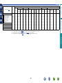
Function
Amp menu
Preset channel block selection
Direct frequency tuning / RDS Search
Cursor operation
Enter
Return
Preset memory registration
Switch search modes
FM/AM switching
Preset channel selection (1 – 8) /
Direct frequency tuning (0 – 9)
TV power on/standby
(Default : marantz)
Switch TV input
(Default : marantz)
Tuning (up/down)
Preset channel selection
Advanced version
1
Press SEARCH/INFO
2 “RT”.
Press TUNER twice to switch the
input source to “TUNER”.
Operation buttons
AMP MENU
SHIFT/TOP MENU
SEARCH/INFO
uio p
ENTER
RETURN
MEMORY
T.MODE
BAND
Basic version
nnTuner (FM/AM) operation
RT (Radio Text)
This unit can play input audio signals in multi-channel surround mode or in stereo mode.
Select a listening mode suitable for the playback contents (movie, music, etc.) or according to your liking.
Basic version
Selecting a listening mode (Surround mode)
Selecting a listening mode
1 Play the selected device (vpage 19).
SURROUND, AUTO, STEREO or P.DIRECT to select a
2 Press
listening mode.
Advanced version
•Each time SURROUND, AUTO, STEREO or P.DIRECT is pressed, the listening
mode is switched.
Various types of surround sound can be selected to match the source being played back. Press
SURROUND until the desired surround mode is reached.
Switches the listening mode to Stereo mode.
Switches the listening mode to DIRECT or PURE DIRECT mode. In DIRECT mode, the audio is
played back exactly how it was recorded.
When PURE DIRECT mode is selected, the PURE DIRECT indicator on the unit lights.
The listening mode can also be selected in the same way for the SURROUND MODE, AUTO and PURE
DIRECT on the main unit.
vSee overleaf
24
Information
This mode detects the type of input digital signal, and automatically selects the corresponding
mode for playback.
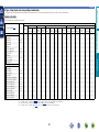
Selecting a listening mode
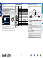
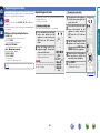
•The following listening modes can be selected using the SURROUND, AUTO, STEREO and P.DIRECT buttons.
•Adjust the sound field effect with the menu “Surr.Parameter” (vpage 49) to enjoy your favorite sound mode.
Operation
button
Input signal
Listening mode
Input signal
Listening mode
All
AUTO z2
All
STEREO
All
DIRECT
PURE DIRECT
AUTO z2
DTS-HD /
DTS Express
PCM multichannel
Multi-channel
NOTE
When you use headphones, you can choose the VIRTUAL, STEREO,
DIRECT and PURE DIRECT mode.
Views on the TV screen or display
q
w
qShows a decoder to be used.
•A DOLBY DIGITAL Plus decoder is displayed as “DOLBY D +”.
wShows a decoder that creates sound output from the surround
back speakers.
•“+ PLgz” indicates the front height sound from front height
speakers.
vSee overleaf
25
Information
z4
DTS-HD HI RES
DTS-HD MSTR
DTS Express
DTS-HD + NEO:6
DTS-HD + PLgx Movie
DTS-HD + PLgx Music
DTS-HD + PLgz
MULTI CH IN
MULTI CH IN 7.1
MULTI IN + Dolby EX
MULTI IN + PLgx Movie
MULTI IN + PLgx Music
MULTI IN + PLgz
MULTI CH STEREO
VIRTUAL
z1 2-channel also includes analog input.
z2 When AUTO mode is selected, the surround mode that is
compatible with the input signal is used for playback.
z3 This mode plays back 2-channel source in 5.1 or 7.1-channel
playback. It cannot be selected when headphones are used, or
when only front speakers are used.
z4 Some listening modes cannot be selected, depending on the
audio format or number of channels of the input signal. For
details, see “Types of input signals, and corresponding surround
modes” (vpage 82).
Advanced version
AUTOz2
STEREO
DOLBY PLgx Movie z3
DOLBY PLg Movie z3
DOLBY PLgx Music z3
DOLBY PLg Music z3
2-channel z1
DOLBY PLgx Game z3
DOLBY PLg Game z3
DTS NEO:6 Cinema z3
DTS NEO:6 Music z3
DOLBY PLgz Height z3
MULTI CH STEREO
VIRTUAL
Multi-channel
AUTOz2
z4
STEREO
DOLBY DIGITAL
DOLBY DIGITAL EX
Dolby Digital DOLBY DIGITAL + PLgx Movie
DOLBY DIGITAL + PLgx Music
DOLBY DIGITAL + PLgz
DOLBY TrueHD
DOLBY TrueHD + EX
Dolby TrueHD DOLBY TrueHD + PLgx Movie
DOLBY TrueHD + PLgx Music
DOLBY TrueHD + PLgz
DOLBY DIGITAL Plus
DOLBY DIGITAL Plus + EX
Dolby Digital
DOLBY DIGITAL Plus + PLgx Movie
Plus
DOLBY DIGITAL Plus + PLgx Music
DOLBY DIGITAL Plus + PLgz
DTS SURROUND
DTS ES DSCRT 6.1
DTS ES MTRX 6.1
DTS 96/24
DTS
DTS + NEO:6
DTS + PLgx Movie
DTS + PLgx Music
DTS + PLgz
Operation
button
Basic version
nnListening mode
Selecting a listening mode
Dolby listening mode
Listening mode type
DOLBY PLgxz1
DOLBY PLgzz2
DOLBY DIGITAL EXz1
DOLBY TrueHD
DOLBY DIGITAL Plus
Listening mode type
DTS NEO:6
DTS SURROUND
DTS ES DSCRT6.1z
DTS ES MTRX6.1z
DTS 96/24
DTS-HD
DTS Express
Description
This mode can be selected when a DTS NEO:6 decoder is used to play back
2-channel source in 6.1/7.1-channel surround sound including the surround
back channel.
There is a “Cinema” mode optimized for movie playback, and a “Music” mode
optimized for music playback.
This mode can be selected when playing sources recorded in DTS.
This mode can be selected when playing sources recorded in DTS-ES.
Provides optimum playback of DTS-ES Discrete signals using surround back.
This mode can be selected when playing sources recorded in DTS-ES.
Surround back channel data encoded in DTS-ES Matrix recording software is
played from the surround back channel.
This mode can be selected when playing sources recorded in DTS 96/24.
This mode can be selected when playing sources recorded in DTS-HD.
This mode can be selected when playing sources recorded in DTS Express.
zzThis can be selected when “Speaker Config.” – “S.Back” is not set to “None”.
PCM multi-channel listening mode
This mode improves the depth, dimension, and expressiveness of the sound
stage by sound field playback including surround back channels.
This mode can be selected when playing sources recorded in Dolby TrueHD.
This mode can be selected when playing sources recorded with Dolby Digital
Plus.
Listening mode type
MULTI CH IN
Description
This mode can be selected when playing multi-channel PCM sources .
vSee overleaf
z1 This can be selected when “Speaker Config.” – “S.Back” is not set to “None”.
z2 This can be selected when “Speaker Config.” – “F.Height” is not set to “None”.
26
Information
DOLBY DIGITAL
Description
This mode can be selected when a Dolby Pro Logic gx decoder is used to
play back 2-channel source in 6.1/7.1-channel surround sound including the
surround back channel.
By adding the surround back channel, a stronger surround feeling is obtained
compared to Dolby Pro Logic g.
There are three playback modes: “Movie” mode that is optimized for movie
playback, “Music” mode that is optimized for music playback, and “Game”
mode that is optimized for game play.
This mode can be selected when a Dolby Pro Logic g decoder is used to play
back 2-channel source in 5.1-channel surround sound with a natural, realistic
feel.
This mode can be selected when a Dolby Pro Logic gz decoder is used to play
back 2-channel source in 7.1-channel surround sound with added front height
channel.
By adding a front height channel, the vertical expression is emphasized,
improving the three-dimensionality of the sound.
This mode can be selected when playing sources recorded with Dolby Digital.
Advanced version
DOLBY PLg
DTS listening mode
Basic version
nnDescription of listening mode types
Selecting a listening mode
Listening mode type
MULTI CH STEREO
VIRTUAL
AUTO
Direct listening mode
Description
Listening mode type
DIRECT
PURE DIRECT
In Direct listening mode, the following items cannot be adjusted.
•Tone (vpage 50)
•MultEQ® (vpage 50)
•Dynamic Volume® (vpage 51) •M-DAX (vpage 52)
STEREO
•Dynamic EQ® (vpage 51)
NOTE
STEREO listening mode
Listening mode type
Description
This mode plays back tracks at high sound quality without passing through the
sound quality adjustment circuits.
This mode plays back tracks at the closest to the original sound quality.
Turn the display of the amplifier off to stop the analogue video circuit. This
suppresses the source of noise that affects sound quality.
•Video signals are only output when HDMI signals are played in the PURE DIRECT mode.
•When in the PURE DIRECT mode, the menu screen is not displayed.
Description
Advanced version
This mode is for enjoying stereo sound from all speakers.
The same sound as that from the front speakers (L/R) is played back at the
same level from the surround speakers (L/R) and surround back speakers (L/R).
This mode is for enjoying surround effects using only the front speakers or
headphones.
In this mode, the type of digital signal input, such as Dolby Digital, Dolby
TrueHD, Dolby Digital Plus, Dolby Digital EX, DTS, DTS-HD, DTS-ES, PCM
(multi-channel) is detected, and the playback mode switches automatically to
the corresponding mode.
If the input signal is analog or PCM (2-channel), stereo playback is used.
Basic version
marantz original listening mode
This is the mode for playing in stereo. The tone can be adjusted.
•Sound is output from the front left and right speakers and subwoofer.
•If multichannel signals are input, they are mixed down to 2-channel audio and
are played.
Information
27
Advanced version
Here, we explain functions and operations that let you make better use of this unit.
F Connections (Advanced connection) vpage 37
F Playback (Advanced operation) vpage 38
F How to make detailed settings vpage 43
Advanced version
F Speaker installation/connection (Advanced) vpage 29
Basic version
Advanced
version
F Other settings vpage 67
28
Information
F Operating the connected devices by remote control unit vpage 68
Procedure for speaker settings
Install
Install
This unit is compatible with Dolby Pro Logic gz (vpage 85),
which offers an even wider and deeper surround sensation.
When using Dolby Pro Logic gz, install front height speakers.
When 7.1ch (Surround back speaker) installed
FL
FR
SW
Install the surround back speakers in a position 60 to 90 cm higher
than ear level.
Front height
speaker
•Point slightly
downwards
C
Surround
speaker
z1
z2
z3
SL
At least 1 mz
SR
60 – 90 cm
Surround back
speaker
•Point slightly
downwards
Front
speaker
SBL
Listening
position
SBR
GViewed from the sideH
Set up speakers (vpage 35)
z1 22˚ – 30˚
zzRecommended for Dolby Pro Logic gz
z2 90˚ – 110˚
z3 135˚ – 150˚
GSpeaker abbreviationsH
NOTE
It is not possible to use the surround back speakers and front height
speakers simultaneously.
FL
FR
C
SW
Front speaker (L)
Front speaker (R)
Center speaker
Subwoofer
SL
SR
SBL
SBR
Surround speaker (L)
Surround speaker (R)
Surround back speaker (L)
Surround back speaker (R)
vSee overleaf
29
Information
Connect (vpage 31)
Advanced version
Here we describe the installation, connection and
setup methods for speakers other than 5.1-channel
speakers. For the installation, connection and setup
methods for 5.1-channel speakers, see C page 4
“Setup Wizard”.
Use Audyssey® Auto Setup function of this unit
to automatically detect the number of connected
speakers and perform optimal settings for the
speakers to be used.
Basic version
Speaker installation/connection (Advanced)
Install
FHL
When 6.1ch (Surround back speaker) installed
When 2.1ch speakers installed
FHR
FL
FR
FL SW
FR
SW
FL
C
C
SW
FR
Basic version
When 7.1ch (Front height speaker) installed
z2
z1
z1
SL
SR
SL
SR
Listening position
Listening position
SB
z1 22˚ – 30˚
z2 22˚ – 45˚
z3 90˚ – 110˚
GSpeaker abbreviationsH
Front speaker (L)
Front speaker (R)
Center speaker
Subwoofer
Surround speaker (L)
Surround speaker (R)
SB Surround back speaker
FHL Front height speaker (L)
FHR Front height speaker (R)
z1 22˚ – 30˚
z2 90˚ – 110˚
Information
FL
FR
C
SW
SL
SR
Listening position
Advanced version
z2
z3
30
Connect
Basic version
•For the method of connecting 5.1-channel speakers, see C page
6 “Connecting the speakers”.
•For the method of connecting the TV, see C page 3 “Connect this
unit to the television using an HDMI cable (sold separately)”.
7.1-channel (Surround back speaker) connection
Advanced version
The illustration on the right shows a connection example for performing
7.1-channel playback using the surround back speakers.
To perform 7.1-channel playback using the surround back speakers,
set “Pre Assign” to “NORMAL” in steps 3 and 4 for “Set up “Pre
Assign”” (vpage 35).
Also use the “Speaker Config.” setting (vpage 55) to set
“S.Back” to “2spkrs”.
Power amplifier
L
R
NOTE
•A power amplifier (sold separately) is required for this connection.
•For speaker cable connections, see C page 6 “Connecting the
speakers”.
•Connect so that the speaker cable core wires do not protrude
from the speaker terminal. The protection circuit may be
activated if the core wires touch the rear panel or if the + and
– sides touch each other (vpage 86 “Protection Circuit”).
•Never touch the speaker terminals while the power supply is
connected. Doing so could result in electric shock (When the
Setup wizard is running, follow the instructions in the Setup
wizard screen for making connections.).
•Use speakers with the speaker impedances shown below.
R
L
Information
Speaker terminals
FRONT
CENTER
SURROUND
IN
Speaker impedance
FR
FL SW
6–8Ω
C
SL
SR
SBL
31
SBR
Connect
Basic version
7.1-channel (Front height speaker) connection
The illustration on the right shows a connection example for performing
7.1-channel playback using the front height speakers.
To perform 7.1-channel playback using the front height speaker,
set “Pre Assign” to “F.HEIGHT” in steps 3 and 4 for “Set up “Pre
Assign”” (vpage 35).
NOTE
Power amplifier
L
Advanced version
•A power amplifier (sold separately) is required for this connection.
•For speaker cable connections, see C page 6 “Connecting the
speakers”.
•For speaker impedance, see page 31.
R
IN
R
L
Information
FHL
FR
FL SW
FHR
C
SL
32
SR
Connect
Basic version
6.1-channel (Surround back speaker) connection
If using only one surround back speaker (with a 6.1-channel
connection), connect to the “L” side of the FL/SBL/HL connector.
For speaker settings in this case, see “When 6.1ch (Surround back
speaker) installed” (vpage 30).
To perform 6.1-channel playback using the surround back speaker,
set “Pre Assign” to “NORMAL” in steps 3 and 4 for “Set up “Pre
Assign”” (vpage 35).
Also use the “Speaker Config.” setting (vpage 55) to set
“S.Back” to “1spkr”.
Advanced version
NOTE
Power amplifier
L
•A power amplifier (sold separately) is required for this connection.
•For speaker cable connections, see C page 6 “Connecting the
speakers”.
•For speaker impedance, see page 31.
IN
L
Information
FR
FL SW
C
SL
SR
SB
33
Connect
The PRE OUT connectors can be used to connect front speakers.
In this case, follow procedures 3 and 4 in “Set up “Pre Assign”” (vpage 35), and set “Pre Assign”
to “FRONT”.
Advanced version
Power amplifier
L
R
FL
SW
Information
IN
R
L
FR
FL SW
NOTE
•For speaker cable connections, see C page 6 “Connecting the speakers”.
•For speaker impedance, see page 31.
34
Basic version
2.1-channel connection
FR
Set up speakers
around items indicate the settings.
First install and connect the speakers to this unit.
1
Set up the
remote control unit
4
2 Connect the setup microphone.
nn Set up the operation mode
Press AMP to set the remote control unit to AMPoperation mode.
Set up “Pre Assign”
Use ui to select “Pre Assign”, and then press
ENTER.
Audyssey Auto Setup
MultEQ
Preparation
Set the following items
if necessary.
Pre Assign
Channel Select
Auto Setup Start
[ENTER] Enter
MultEQ
Audyssey Auto Setup
[RETURN] Cancel
Preparation
Connect the speakers and place them according
to the recommendations in the manual.
Pre Assign
Next
[ENTER] Enter
[RETURN] Cancel
Pre Assign
MultEQ
NORMAL
“Next”, and then press
3 Select
ENTER.
[RETURN] Return
vSee overleaf
35
Information
When the setup microphone is
connected, the following screen is
displayed.
Press AMP
Advanced version
Before Auto Setup measurement, the settings shown below can be made.
•Changing the amplifier assignment (Pre Assign)
The signal output from the FL/SBL/HL and FR/SBR/HR connectors on PRE OUT of the amplifier can be switched in accordance with the speaker environment (vpage 35 “Set up “Pre Assign””).
•Setting the channels to be used (Channel Select)
If channels that are not to be used are set in advance, measurement for the set channels is skipped, and measuring time can be reduced. You can also change the number of surround back speakers (vpage 36
“Set up “Channel Select””).
Basic version
Here we describe how to set up speakers other than 5.1-channel speakers.
For the method of setting up 5.1-channel speakers, see C page 4 “Setup Wizard”.
Set up speakers
speakers.
7
Set up “Channel Select”
Use ui to select “Channel Select”, and then press
ENTER.
Audyssey Auto Setup
NORMAL
FRONT
6
Preparation
Set the following items
if necessary.
Set for connecting the surround back speakers to
the FL/SBL/HL and FR/SBR/HR connectors in PRE
OUT.
Set for no measuring of a surround back speaker.
o p to set whether or not a subwoofer channel
10 Use
is measured.
Auto Setup Start
[ENTER] Enter
Set for connecting the front speakers to the FL/SBL/
HL and FR/SBR/HR connectors in PRE OUT.
Measure
Set for measuring a surround back speaker.
(1 sp)
Skip
Pre Assign
Channel Select
Set for connecting the front height speakers to the
FL/SBL/HL and FR/SBR/HR connectors in PRE OUT.
Measure
Set for measuring two surround back speakers.
(2 sp)
[RETURN] Cancel
Measure Set for measuring a subwoofer.
Skip
Set for no measuring of a subwoofer.
11 Press RETURN.
Press RETURN to exit the “Pre Assign” setting.
Proceed to page 13 STEP 1 Preparation
Channel Select
NOTE
Measure (2 sp)
Measure
[RETURN] Return
8 Use ui to select a channel.
Surround
Back
Select the number of surround back speakers to be
used. In this case, go to step 9.
•“Surround Back” can be set when “Pre Assign” is
set to “NORMAL”.
Subwoofer
Select for no subwoofer to be used. In this case, go
to step 10.
36
After performing Audyssey® Auto Setup, do not change the speaker
connections or subwoofer volume. In event of a change, perform
Audyssey® Auto Setup again.
Information
Surround Back
Subwoofer
step 6.
Advanced version
F.HEIGHT
MultEQ
o p to set whether or not a surround back
9 Use
channel is measured.
Basic version
Use o p to select the
5 configuration
of the connected
qYou can control other marantz products through this unit with the remote control unit by connecting the
Basic version
REMOTE CONTROL connectors on each unit.
•The signal transmitted from the remote control unit is received by the remote sensor on this unit.
Then the signal is sent to the connected device through REMOTE CONTROL connector. Therefore
you need to aim the remote control only at the this unit.
•Set the remote control switch located on the rear panel of the connected audio component to
“EXTERNAL” or “EXT.” to use this feature.
•If a marantz power amplifier (excluding certain models) is connected to any of these connectors, the
power of the power amplifier switches to on/standby in conjunction with the ON/STANDBY button
of the this unit.
wWhenever external infrared sensors or similar devices are connected to REMOTE CONTROL IN
connector of the this unit, be sure to always disable operation of the infrared sensor on the this unit
(vpage 67 “Remote control settings”).
Advanced version
Connections (Advanced connection)
Connecting the remote control connectors
q
RC OUT
NOTE
IR receiver
w
Be sure to set to “enable” when external infrared sensors or similar devices are not connected. Otherwise,
the unit will be unable to receive remote control commands.
REMOTE
CONTROL
REMOTE
CONTROL
IN OUT
IN OUT
IN OUT
CD recorder
DVD player
CD player
EXTERNAL INTERNAL
EXTERNAL INTERNAL
EXTERNAL INTERNAL
Information
REMOTE
CONTROL
37
Basic version
Playback (Advanced operation)
Convenient functions
Settings (vpage 11)
HDMI control function
Playback (Basic operation) (vpage 18)
•This unit power off can be linked to the TV power off step.
•You can switch audio output devices with a TV operation.
When you set “Output audio from amp” in the TV audio output
setup operation, you can switch the amp power on.
•You can adjust this unit volume in the TV volume adjustment
operation.
•You can switch this unit input sources through linkage to TV
input switching.
•When playing the player, this unit input source switches to the
source for that player.
•If you switch the input source of the unit to “TV”, you can
play TV audio with this unit (vpage 5 “About ARC (Audio
Return Channel) function”).
•When “HDMI Control” (vpage 58) in the menu is set to
“ON”, signals input to the HDMI input connector are output to
the television or other device connected to the HDMI output
connector, even if the power of this unit is in standby (passthrough function).
•To play the audio of a TV that does not support the ARC function
with the unit, connect the TV with an optical digital connection.
•To use the pass-through function, connect an HDMI connection
device that is compatible with HDMI control.
Set “HDMI Control” (vpage 58) to “ON“.
the power on for all the devices connected by
2 Turn
HDMI cable.
the HDMI control function for all devices
3 Set
connected by HDMI cable.
•Please consult the operating instructions for the connected devices
to check the settings.
•Carry out steps 2 and 3 should any of the devices be unplugged.
the television input to the HDMI input
4 Switch
connected to this unit.
this unit input to the HDMI input source and
5 Switch
check if the picture from the player is ok.
you turn the TV’s power to standby, check
6 When
that the power of this unit also goes to standby.
If the HDMI control function does not operate properly, check the
following points.
•Is the TV or player compatible with the HDMI control function?
•Is “HDMI Control” (vpage 58) set to “ON”?
•Is “P.Off Control” (vpage 58) set to “All” or “Video”?
•Are the HDMI control function settings of all devices correct?
vSee overleaf
BD
38
Information
nn HDMI control function (vpage 38)
nn Sleep timer function (vpage 39)
nn Adjusting the volume of the speakers
(vpage 40)
nn Dual backup memory function (vpage 41)
nn Panel lock function (vpage 41)
nn Various memory functions (vpage 42)
nnOperations possible by HDMI control
the HDMI output connector corresponding with
1 Set
the HDMI control function.
Advanced version
Selecting a listening mode (Surround mode)
(vpage 24)
If you connect the unit and an HDMI control function compatible TV or
player with an HDMI cable and then enable the HDMI control function
setting on each device, the devices will be able to control each other.
nnSetting procedure
Convenient functions
The power automatically goes into standby once the set time has
elapsed.
This is convenient for playing sources while going to sleep.
Press SLEEP and display the time you
want to set.
The “SLEEP” indicator on the display lights.
OFF
120
110
10 min
20
30
40
100
90
80
70
50
60
To confirm the countdown time before putting the
unit to sleep
Advanced version
•The time switches as shown below each
time SLEEP is pressed.
Press SLEEP.
“Sleep : zmin” appears on the display.
zzCountdown time
The sleep timer setting is canceled if this unit’s power is set to
standby.
39
Information
To cancel the sleep timer
Press SLEEP to set “OFF”.
The “SLEEP” indicator on the display turns off.
BD
Basic version
Sleep timer function
NOTE
•When “HDMI Control” is set to “ON”, it consumes more
standby power.
•The HDMI control function controls operations of a TV that is
compatible with the HDMI control function. Make sure that the TV
and HDMI are connected when you perform HDMI control.
•Some functions may not operate depending on the connected TV
or player. Check the owner’s manual of each device for details
beforehand.
•When “P.Off Control” on the menu is set to “OFF” (vpage 58),
this unit is not set to standby even if the connected device is in the
standby mode.
•When connection changes are implemented, such as adding
connections to HDMI devices, linked operations may be initialized.
In this case, you will need to reconfigure the settings.
•When “HDMI Control” is set to “ON”, it is not possible to assign an
HDMI connector to “TV” at “Input Assign” (vpage 64).
•Should any of the operations below be performed, the interlocking
function may be reset, in which case, repeat steps 2 and 3.
•“Input Assign” – “HDMI” (vpage 64) setting has changed.
•There is a change to the connection between the devices and the
HDMI, or an increase in devices.
Convenient functions
You can adjust the channel level either according to the playback
sources or to suit your taste, as described below.
nnAdjusting the volume of the different speakers
Press AMP to set the remote
1 control
unit to AMP-operation
mode.
Channel Level
Front L
Front R
Subwoofer
-8.5dB
-11.5dB
•You can directly turn “OFF” the subwoofer outputs during
2-channel playback in DIRECT or STEREO mode.
Select “Subwoofer” and use o p to select “ON” or “OFF”.
Channel Level
Front L
Front R
-8.5dB
-11.5dB
Subwoofer
OFF
nnAdjusting the volume of groups of speakers
(Fader function)
This function lets you adjust (fade) the sound all at once from the
front (front speaker / front height speaker / center speaker) or rear
(surround speaker / surround back speaker).
AMP to set the remote
1 Press
control unit to AMP-operation
mode.
2 Press CH LEVEL.
i to select “Fader”, then
3 Press
select the item to be adjusting
using o p.
0.0dB
Channel Level
Subwoofer
When a headphone jack is inserted, the headphone channel level can
be adjusted.
ON
Fader
The speaker that can be set switches each time one of the
buttons is pressed.
-1.0dB
-1.0dB
-1.0dB
+0.5dB
0.0dB
0.0dB
Front
Rear
4 Use o p to adjust the volume of the speakers.
(o : front, p: rear)
•The fader function does not affect the subwoofer.
•The fader can be adjusted until the volume of the speaker is adjusted
to the lowest value of –12 dB.
BD
40
Information
3 Use ui to select the speaker.
Front L
Front R
Center
Subwoofer
Surround L
Surround R
Advanced version
2 Press CH LEVEL.
4
Use o p to adjust the volume.
Basic version
Adjusting the volume of the speakers
Convenient functions
Panel lock function
The unit stores settings information in nonvolatile memory even when the main power supply is turned off. Using the Dual Backup Memory
function, you can write settings information to another memory area to back up saved settings for recovery anytime as needed.
To prevent accidental operation of this unit, you can disable operation
of the buttons on the front panel.
nnRemembering set details (Backup)
nnRecalling remembered details (Recovery)
MENU
ON/STANDBY DISPLAY PURE DIRECT
Basic version
Dual backup memory function
DISPLAY
u
nnDisabling all key button operations
Set the unit in the state you want remembering, and press
and hold u and MENU for at least 3 seconds.
NOTE
“MEMORY LOAD” is shown in the display, and the remembered
details are recalled.
NOTE
•The volume is not remembered.
•If remembered details are overwritten, the previously remembered
contents are deleted.
•If there is no remembered data, “NO BACKUP” is shown in the
display, and no remembered details are recalled.
•As the volume cannot be recalled, it returns to the factory setting
volume.
Press ON/STANDBY while you press and hold PURE
DIRECT and BAND with the unit in standby mode.
“Panel Lock:ON” appears on the display and all button operations
except ON/STANDBY are disabled.
nnDisabling all button operations except VOLUME
Press ON/STANDBY while you press and hold PURE
DIRECT and DISPLAY with the unit in standby mode.
“Panel Lock:ON” appears on the display and all button operations
except ON/STANDBY and VOLUME are disabled.
nnCanceling the Panel lock function
Press ON/STANDBY while you press and hold PURE
DIRECT and RETURN with the unit in standby mode.
The Panel lock function is canceled.
Even when the Panel lock function is set, you can operate the unit
using the remote control unit.
BD
41
Information
“MEMORY SAVING” is shown in the display, and the setting details
are remembered.
Press and hold u and DISPLAY together for at least 3
seconds.
Advanced version
u
RETURN BAND VOLUME
Convenient functions
Basic version
Various memory functions
nnPersonal memory plus function
This function sets the settings (input mode, surround mode, HDMI
output mode, MultEQ®, Dynamic EQ®, audio delay etc.) last
selected for the individual input sources.
Advanced version
The surround parameters, tone settings and the volumes of the
different speakers are stored for the individual surround modes.
nnLast function memory
This function stores the settings which were made before going
into the standby mode.
When the power is turned back on, the settings are restored.
Information
BD
42
Basic version
How to make detailed settings
Menu map
For menu operation, connect a TV to this unit and display the menu on the TV screen. For menu operations, see the following page.
Setting items
Audio Adjust
Detailed items
Manual EQ
M-DAX
Menu
Audio Adjust
Information
Setup Wizard
System Setup
Input Setup
Items that only need to be set
once
Set these for example upon purchase.
Once these items are set, there is
no need to set them again unless
the speaker layout or the connected
speakers have been changed.
BD
Audio Delay
Status
Audio Signal
HDMI Information
Speaker Setup
HDMI Setup
Audio Setup
Option Setup
Language
Auto Preset
Input Setup
Preset Skip
Preset Name
Displayed items of the “Input
Input Assign
Setup” menu differs, depending on
Video
the selected input source.
Input Mode
Rename
Source Level
43
Page
49
50
50
52
52
52
53
53
53
C4
55
58
59
59
61
63
63
63
64
65
66
66
66
Information
Information
Surr.Parameter
Tone
AudysseySettings
Setup Wizard
Manual EQ
RESTORERSystem Setup
Audio Delay
Description
Adjusts surround sound parameters.
Adjusts the tonal quality of the sound.
Makes Audyssey MultEQ®, Audyssey Dynamic EQ® and Audyssey Dynamic
Volume® settings.
Uses the graphic equalizer to adjust the tone of each speaker.
Expands the low and high frequency components of compressed audio to enable
richer audio playback.
Compensates for incorrect timing between video and audio.
Shows information about current settings.
Shows information about audio input signals.
Displays the HDMI input/output signals and HDMI monitor information.
Perform the installation, connection, and setup procedures to prepare the unit for
operation following guidance.
Sets the speaker size and distance, the channel level, etc.
Makes settings for HDMI video/audio output.
Makes settings for audio playback.
Makes various other settings.
Sets the language for display the menu on the TV screen.
Uses the auto preset function to program radio stations.
Sets the preset memories that you do not want to display when tuning.
Assigns name to a preset memory.
Changes input connector assignment.
Makes the video settings.
Sets the audio input mode and decode mode.
Changes the display name for this source.
Adjusts the playback level of the audio input.
Advanced version
Surr.Parameter
Tone
Audyssey Settings
Examples of menu screen displays
GExample 1H Menu selection screen (Top menu)
GExample 2H Audyssey® Auto Setup screen
(with illustration)
Menu
q
Surr.Parameter
Tone
AudysseySettings
Manual EQ
M-DAX
Audio Delay
w
y
MultEQ
Preparation
Set the following items
if necessary.
u
Pre Assign
Channel Select
Auto Setup Start
qCurrently selected setup item
wList of currently selected setup
subcategory
[ENTER] Enter
[RETURN] Cancel
tHistory icon
yOperation guidance text
uIllustration
iOperation button guidance
nn List
Selected item
•Switch the selected item using ui.
Input Setup
Input Assign
Video
Input Mode
Rename
Source Level
System Setup
e
Speaker Setup
HDMI Setup
Audio Setup
Option Setup
Language
Auto Setup
Pre Assign
Speaker Config.
Bass Setting
Distance
Channel Level
Crossover Freq.
Proceed to the
subcategory
(Use p or ENTER to switch.)
r
eSelected setup item
rOptions of the selected setup item
BD
44
Information
Press i to select “System
Setup” and then press p.
(Or press ENTER.)
i
Advanced version
Audio Adjust
Information
Setup Wizard
System Setup
Input Setup
t
Audyssey Auto Setup
Basic version
Typical examples are described below.
Examples of menu and front display
Menu display
Top menu display
Front display
Description
qPress AMP MENU to display the menu
screen.
w TV screen: Displays the selected line.
Display: Displays the selected item.
•Use ui to move to the item you want to set.
Menu
w
Audio Adjust
Information
Setup Wizard
System Setup
Input Setup
Input Assign
Default
BD
DVD
SAT
GAME
AUX
[
G HDMI H
] Select
G DIGITAL H
w
q TV screen: Displays the selected line.
Display: Displays the selected item.
•Use ui to move to the item you want to set.
wPress ENTER to set to the mode in which the setting can be made.
G COMPONENT H
1-RCA
2-RCA
None
None
None
None
COAX
None
None
None
ENTER. [
[ENTER]
Press Enter
BD
[HDMI1 ]
Display when resetting
[
HDMI1
HDNI2
HDMI3
HDMI4
None
H
e G DIGITAL
None
1-RCA
2-RCA
None
None
None
COAX
None
None
None
Rename
] Select
[ENTER] Enter
Default
BD
BD
DVD
DVD
SAT
SAT
GAME
GAME
AUX
AUX
TV
TV
•HDMI1 –
G COMPONENT H
[
[
Press ENTER.
] Return
q
Press ENTER.
Rename
Default?
Return settings to the default?
w
BD
Yes
e 0 1 is displayed at the sides of items whose setting can be
changed. Use o p to change to the desired setting.
qPress u to select “Default”, then press ENTER.
wPress o to select “Yes”, then press ENTER.
] Return
Default
[ENTER] Enter
e
No
45
: • No
Information
[1/2]
BD
G HDMI H
q
Press ENTER.
] Return
Input Assign
Default
BD
DVD
SAT
GAME
AUX
–
[1/2]
q
HDMI1
HDNI2
HDMI3
HDMI4
None
Audio Adjust
Advanced version
Display when changing settings
Surr.Parameter
Tone
AudysseySettings
Manual EQ
M-DAX
Audio Delay
Basic version
Below we describe typical examples of displays on the TV screen and on the set’s display window.
Inputting characters
Method for inputting characters
Method
Using the keyboard
screen
Keyboard screen
Using the keyboard screen
nnDisplay of a keyboard input screen
the screen for inputting
1 Display
characters (vpage 43
“Menu map”).
Rename
Operations
•Operating with the remote control unit.
•Select a character on the TV screen to
input characters.
BD
e
A
N
0
$
r
[a/A] [SPACE] [
t
Q0
BD
w
[
] Select
[SHIFT] a/A
B
O
1
%
C
P
2
&
D
Q
3
‘
E
R
4
(
][
y
F
S
5
)
G
T
6
z
H
U
7
+
q
I
V
8
,
J
W
9
;
K
X
!
<
L
Y
“
=
M
Z
#
>
] [INSERT] [DELETE] [OK]
u
i
o
[ENTER] Input
[RETURN] Cancel
[SEARCH] CursorMode
or [→].
wPress ENTER to place the
cursor at the character to be
changed.
Each time ENTER is pressed, the
cursor moves by one character.
a character to be input with uio p then
3 Select
press ENTER.
•The types of characters that can be input are as shown below.
GUpper case characters/Numbers/SymbolsH
ABCDEFGHIJKLMNOPQRSTUVWXYZ
0123456789
!“#$ %&’()z+,;<=>
GLower case characters/Numbers/SymbolsH
abcdefghijklmnopqrstuvwxyz
0123456789
.@-_/:˜?[\]^`{|}
Information
q Character input section (Maximum 8 characters)
wCursor
e Keyboard section
r Uppercase and lowercase switch key
t Space key
y Cursor keys
u Insert key
i Delete key
o OK key
Q0 Guide for operation buttons
a character to be changed.
2 Select
qPress uio p to select [←]
•When you press SHIFT/TOP MENU while you type in, you can
change uppercase characters to lowercase and vice versa.
4 Repeat steps 2 and 3 to change the name.
5 Use uio p to select [OK], then press ENTER.
vSee overleaf
BD
46
Advanced version
•Operating with the remote control unit.
Using the cursor buttons
•Use uio p and ENTER to input
(Cursor mode screen)
characters.
Basic version
You can change the names as desired using the “Preset Name”
(vpage 63) and “Rename” (vpage 66).
For inputting characters, there are two methods, as shown below.
Inputting characters
Using the cursor buttons
nnDisplay of a cursor mode screen
Rename
BD
DVD
SAT
GAME
AUX
TV
[ENTER] Enter
[ ] Input
[SEARCH] Keyboard
q
w
[RETURN] Cancel
q Character input section (Maximum 8 characters)
w Guide for operation buttons
A cursor mode screen is displayed.
o p to set the cursor to the character you want
3 Use
to change.
ui to change the character,
4 Use
then press ENTER.
•The types of characters that can be input
are as shown below.
GUpper case charactersH
•When you press SHIFT/TOP MENU while you type in, you can
change uppercase characters to lowercase and vice versa.
steps 3 and 4 to change the name then press
5 Repeat
ENTER to register it.
BD
47
Information
ABCDEFGHIJKLMNOPQRSTUVWXYZ
GLower case charactersH
abcdefghijklmnopqrstuvwxyz
GSymbolsH ! “ # $ % & ‘ ( ) z + , - . / : ; <
=>?@[\]^_`{|}˜
GNumbersH 0123456789 (Space)
Advanced version
Default
BD
DVD
SAT
GAME
AUX
TV
[1/2]
the screen for inputting characters
1 Display
(vpage 43 “Menu map”).
Press SEARCH/INFO while a keyboard screen is
2 displayed.
Basic version
Cursor mode screen
The sound being played in the surround mode can be adjusted to your liking.
The items (parameters) that can be adjusted depend on the signal being input and the currently
set surround mode. For details on the adjustable parameters, see “Surround modes and surround
parameters” (vpage 80).
Items that can be set with the “Audio Adjust” procedure
Surr.Parameter (vpage 49)
NOTE
Tone (vpage 50)
Some setting items cannot be set while playback is stopped. Make the settings during playback.
Audyssey Settings (vpage 50)
Press AMP MENU to set the remote control unit to AMP1 operation
mode.
Manual EQ (vpage 52)
M-DAX (vpage 52)
The menu is displayed on the TV screen.
2 Use ui to select the menu to be set or operated.
3 Press ENTER or p to enter the setting.
Audio Delay (vpage 52)
Information
•To return to the previous item, press RETURN .
•Exiting the Menu, press AMP MENU while the menu is displayed.
The menu display disappears.
Advanced version
Menu operation
BD
Basic version
Audio Adjust
48
Audio Adjust
Setting items
Default settings are underlined.
C.Width
Assign center channel
signal to front left and right
channels for wider sound.
Height Gain
Control the front height
channel volume.
Adjust surround sound parameters. It may not be possible to set this item depending on the input signal
(vpage 80 “Surround modes and surround parameters”).
Setting items
Setting details
DRC
Compress dynamic range
(difference between loud
and soft sounds).
D.Comp
Compress dynamic range
(difference between loud
and soft sounds).
LFE
Adjust the low-frequency
effects level (LFE).
Auto : Automatic dynamic range compression on/off control according to
source. This can be set in the Dolby TrueHD mode.
Low / Middle / High : These set the compression level.
OFF : Dynamic range compression always off.
OFF : Turn dynamic range compression off.
Low / Middle / High : These set the compression level.
This can also be set by pressing HT-EQ.
Low : Reduce the front height channel volume.
Middle : Front height channel sound is output with standard sound
volume.
High : Increase the front height channel volume.
NOTE
C.Image
Assign center channel
signal to front left and right
channels for wider sound.
Panorama
Assign front L/R signal also
to surround channels for
wider sound.
Dimension
Shift sound image center
to front or rear to adjust
playback balance.
Default
The “Surr.Parameter”
settings are returned to the
default settings.
–10dB – 0dB
For proper playback of the different sources, we recommend setting
to the values below.
•Dolby Digital sources : “0dB”
•DTS movie sources : “0dB”
•DTS music sources : “–10dB”
0.0 – 1.0 (0.3)
When you select “Default” and press ENTER,
the “Return settings to the default?” prompt
is displayed. Select either “Yes” or “No”, and
press ENTER.
vSee overleaf
ON : Set.
OFF : Do not set.
0 – 6 (3)
BD
“Height Gain” is displayed for the following settings.
•When “Pre Assign” (vpage 55) is set to “F.HEIGHT”.
•When the “Speaker Config.” – “F.Height” setting (vpage 56) is set
other than to “None”.
•When surround mode is “PLgz” or the PLgz decoder is used.
Yes : Reset to the defaults.
No : Do not reset to the defaults.
49
Information
ON : “HT-EQ” is used.
OFF : “HT-EQ” is not used.
0 – 7 (3)
Advanced version
HT-EQ
Soften the treble range
of movie soundtracks for
better understanding.
Setting details
Basic version
Surr.Parameter
Audio Adjust
Audyssey Settings
Adjust the tonal quality of the sound.
Set Audyssey MultEQ®, Audyssey Dynamic EQ® and Audyssey Dynamic Volume®. These can be selected
after Audyssey® Auto Setup has been performed. For additional information on Audyssey technology,
please see page 85.
Setting items
Setting details
Tone Control
ON : Allow tone adjustment (bass, treble).
Set the tone control function OFF : Playback without tone adjustment.
to ON and OFF.
“Tone Control” can be set when “Dynamic EQ®” (vpage 51) is
set to “OFF”.
Default settings are underlined.
NOTE
NOTE
The tone cannot be adjusted in the “DIRECT” mode.
Bass
–6dB – +6dB
Adjust low frequency range
“Bass” can be set when “Tone Control” is set to “ON”.
(bass).
Treble
–6dB – +6dB
Adjust high frequency range
“Treble” can be set when “Tone Control” is set to “ON”.
(treble).
Setting details
Audyssey : Optimize the frequency response of all speakers.
Audyssey Byp.L/R : Optimize frequency response of speakers except
front L and R speakers.
Audyssey Flat : Optimize frequency response of all speakers to flat
response.
Manual : Apply frequency response set with “Manual EQ” (vpage 52).
OFF : Turn “MultEQ®” equalizer off.
•“Audyssey”, “Audyssey Byp. L/R” and “Audyssey Flat” can be selected
after Audyssey® Auto Setup has been performed. “Audyssey” is
automatically selected after performing Audyssey® Auto Setup. When
“Audyssey”, “Audyssey Byp. L/R” or “Audyssey Flat” is selected,
illuminates.
•After running Audyssey® Auto Setup, if the Speaker Configuration,
Distance, Channel Level, and Crossover Frequency have changed
without increasing the number of speakers measured, only
illuminates.
NOTE
•“MultEQ®” and “Manual” cannot be selected when “EQ Customize” is
set to “Not Used” (vpage 59).
•When using headphones, “MultEQ®” is automatically set to “OFF”.
“MultEQ®”, “Dynamic EQ®” and “Dynamic Volume®” settings are stored for each input source.
vSee overleaf
BD
50
Information
Setting items
MultEQ®
MultEQ® corrects both time
and frequency response
problems in the listening
area based on Audyssey®
Auto Setup calibration. We
recommend “Audyssey”.
MultEQ® is the prerequisite
function for Dynamic EQ®
and Dynamic Volume®.
Advanced version
•If you have not performed Auto Setup, or if you change the speaker settings after performing Auto Setup,
you may not be able to select Dynamic EQ®/Dynamic Volume®.
In this case, either perform Audyssey® Auto Setup over again or perform “Restore” (vpage 17) to
return to the settings after Audyssey® Auto Setup was run.
•When HD Audio for which the sampling frequency exceeds 96 kHz is played back, the “Audyssey
Settings” cannot be set.
Basic version
Tone
Audio Adjust
Setting details
®
ON : Use Dynamic EQ .
OFF : Do not use Dynamic EQ®.
or
is displayed when set to “ON”.
0dB (Film Ref) : This is the default setting and should be used when
listening to movies.
5dB : Select this setting for content that has a very wide dynamic range,
such as classical music.
10dB : Select this setting for jazz or other music that has a wider dynamic
range. This setting should also be selected for TV content as that is usually
mixed at 10 dB below film reference.
15dB : Select this setting for pop/rock music or other program material
that is mixed at very high listening levels and has a compressed dynamic
range.
Setting details
Heavy : Most adjustment to loudest and softest sounds.
Medium : Medium adjustment to loudest and softest sound.
Light : Least adjustment to loudest and softest sounds.
OFF : Do not use “Dynamic Volume®”.
•
is displayed when set to “Heavy”,
“Medium” or “Light”.
•If “Dynamic Volume®” is set to “Yes” in
Auto Setup (vpage 15), the setting is
automatically changed to “Medium”.
•This can also be set by pressing DYN VOL.
Each time DYN VOL is pressed, the setting is changed as shown below.
Dynamic Volume : OFF
Dynamic Volume : Heavy
Dynamic Volume : Light
Dynamic Volume : Medium
Advanced version
Setting items
Dynamic Volume®
Solve the problem of large
variations in volume level
between TV, movies and
other content (between
quiet passages and
loud passages, etc.) by
automatically adjusting to
the user’s preferred volume
setting.
Basic version
Setting is enabled when “Dynamic EQ®” is “ON” (vpage 51).
Information
Setting items
Dynamic EQ®
Solve the problem of
deteriorating sound quality
as volume is decreased
by taking into account
human perception and
room acoustics. Works with
MultEQ®.
Reference Offset
Audyssey Dynamic EQ® is
referenced to the standard
film mix level. It makes
adjustments to maintain
the reference response
and surround envelopment
when the volume is turned
down from 0 dB. However,
film reference level is not
always used in music or
other non-film content.
Dynamic EQ® Reference
Level Offset provides three
offsets from the film level
reference (5 dB, 10 dB, and
15 dB) that can be selected
when the mix level of the
content is not within the
standard.
BD
51
Audio Adjust
M-DAX
Default settings are underlined.
Compressed audio formats such as MP3, WMA (Windows Media Audio) and MPEG-4 AAC reduce the
amount of data by eliminating signal components that are hard for the human ear to hear. The M-DAX
function generates the signals eliminated upon compression, restoring the sound to conditions near those
of the original sound before compression. It also corrects the sense of volume of the bass to obtain richer
sound with compressed audio signals.
Use the graphic equalizer to adjust the tone of each speaker.
“Manual EQ” can be set when “MultEQ®” setting (vpage 50) is “Manual”.
Setting items
Setting details
Adjust Channel
Correct the tone of each
speaker.
q Select the speaker tone adjustment method.
All : Adjust the tone of all speakers together.
L/R : Adjust the tone of left and right speakers together.
Each : Adjust the tone of each speaker.
w Select the speaker.
e Select the adjustment frequency band.
63Hz / 125Hz / 250Hz / 500Hz / 1kHz / 2kHz / 4kHz / 8kHz / 16kHz
•Select the speakers you want to adjust when “L/R” or “Each” is
selected.
r Adjust the level.
–20.0dB – +6.0dB (0.0dB)
Curve Copy
Yes : Copy.
Copy “Audyssey Flat” curve No : Do not copy.
from MultEQ®.
Setting details
OFF : Do not use M-DAX.
Low : Optimized mode for compressed sources with normal highs.
Mid : Apply suitable bass and treble boost for all compressed sources.
High : Optimized mode for compressed sources with very weak highs.
•This item can be set with analog signals or PCM signal (fs = 44.1/48 kHz) is
input.
•“M-DAX” settings are stored for each input source.
•When set to “OFF”, the M-DAX indicator on the front panel switches off.
•This cannot be set when the surround mode is set to “DIRECT” or “PURE
DIRECT”.
•This can also be set by pressing M-DAX.
Audio Delay
While viewing video, manually adjust the time to delay audio output.
Setting details
0ms – 200ms
When you select “Default” and press ENTER,
the “Return settings to the default?” prompt
is displayed. Select either “Yes” or “No”, and
press ENTER.
BD
Default settings are underlined.
•This item can be set within the range of 0 to 100 ms when “Auto Lip Sync” (vpage 58) is set to
“ON” and when a TV compatible with Auto Lip Sync is connected.
•Store “Audio Delay” for each input source.
•Audio Delay for game mode can be set when “Video Mode” (vpage 65) is set to “Auto” or
“Game”.
52
Information
•“Curve Copy” is displayed after Audyssey® Auto Setup has been
performed.
•When you select “Curve Copy” and press ENTER, the “Set EQ curve to
Audyssey Flat?” prompt is displayed. Select either “Yes” or “No”, and
press ENTER.
Yes : Reset to the defaults.
No : Do not reset to the defaults.
Advanced version
Default
The “Manual EQ” settings
are returned to the default
settings.
Default settings are underlined.
Basic version
Manual EQ
Basic version
Information
Show information about receiver settings, input signals, etc.
Items
Setting details
The information displayed differs according to the input source.
Select Source / Name / Surround Mode / Input Mode /
Decode Mode / Assign / Video Select / Video Mode /
Content Type etc.
Audio Signal
Show information about
audio input signals.
Surround Mode : The currently set surround mode.
Signal : The input signal type.
fs : The input signal’s sampling frequency.
Format : The number of channels in the input signal (front, surround, LFE).
Offset : The dialogue normalization correction value.
Flag : This is displayed when inputting signals including a surround back
channel. “MATRIX” is displayed with Dolby Digital EX and DTS-ES Matrix
signals, “DISCRETE” with DTS-ES Discrete signals.
Advanced version
Status
Show information about
current settings.
Dialogue normalization function
Information
This function is automatically activated when playing Dolby Digital
sources.
It automatically corrects the standard signal level for individual program
sources.
The correction value can be checked using the STATUS on the main unit.
The figure is the corrected value.
This cannot be changed.
HDMI Information
Show information about
HDMI input/output signals
and monitor.
Signal Info.
•Resolution / Color Space / Pixel Depth
Monitor Info.
•Interface / Support Resolution
Even if STATUS OSD is pressed, the Information screen (Status, Audio Signal,
HDMI Information) can be displayed.
BD
53
Set when changing Audyssey® Auto Setup settings, or when changing the audio, video, display
or other settings.
•If you change the speaker settings after performing Audyssey® Auto Setup, it will not be
possible to set Audyssey MultEQ®, Audyssey Dynamic EQ® and Audyssey Dynamic Volume®
(vpage 50, 51).
•Can be used without changing the settings. Please set if necessary.
Items that can be set with the “System Setup” procedure
Speaker Setup (vpage 55)
HDMI Setup (vpage 58)
Menu operation
Audio Setup (vpage 59)
Press AMP MENU to set the remote control unit to AMPoperation mode.
Option Setup (vpage 59)
The menu is displayed on the TV screen.
Language (vpage 61)
2
3 Press ENTER or p to enter the setting.
Press ui to select the menu to be set or operated.
BD
Information
•To return to the previous item, press RETURN .
•Exiting the Menu, press AMP MENU while the menu is displayed.
The menu display disappears.
Advanced version
1
Basic version
System Setup
54
System Setup
Default settings are underlined.
Speaker Config.
(Continued)
Perform when setting the speakers manually or when changing settings made in Audyssey® Auto Setup.
•If you change the speaker settings after performing Audyssey® Auto Setup, it will not be possible to
select Audyssey MultEQ®, Audyssey Dynamic EQ® and Audyssey Dynamic Volume® (vpage 50,
51).
•“System Setup” can be used without changing the settings. Please set if necessary.
Setting details
NORMAL : Set for connecting the surround back speakers to the FL/SBL/
HL and FR/SBR/HR connectors in PRE OUT.
F.HEIGHT : Set for connecting the front height speakers to the FL/SBL/HL
and FR/SBR/HR connectors in PRE OUT.
FRONT : Set for connecting the front speakers to the FL/SBL/HL and FR/
SBR/HR connectors in PRE OUT.
When “Front” is set to “Small”, “Subwoofer” is automatically set to
“Yes”.
Surround : Set the presence and size of the surround speakers.
•Large : Use a large speaker that can adequately play back low
frequencies.
•Small : Use a small speaker that has inadequate playback capacity for
low frequencies.
•None : Select when the surround speakers are not connected.
A power amplifier (sold separately) is required for this connection.
NOTE
•When “Subwoofer” is set to “No”, “Front” is automatically set to
“Large”.
•When “Front” is set to “Small”, “Center”, “Surround“, “S.Back” and
“F.Height” can not be set to “Large”.
Center : Set the presence and size of the center speaker.
•Large : Use a large speaker that can adequately play back low
frequencies.
•Small : Use a small speaker that has inadequate playback capacity for
low frequencies.
•None : Select when a center speaker is not connected.
•2spkrs : Use two surround back speakers.
•1spkr : Use only one surround back speaker. When you select this
setting, connect the surround back speaker to the left (L) channel.
Even when the “S.Back“ setting is other than “None”, sound may
not be emitted from the surround back speaker, depending on the
playback source.
NOTE
When “Pre Assign” setting (vpage 55) is “NORMAL”, you can make
the “S.Back” setting.
“Large” is not displayed when “Front” is set to “Small”.
vSee overleaf
BD
55
Information
•When “Surround” is set to “Large”, “S.Back” and “F.Height” can be
set to “Large”.
•When “Surround” is set to “None”, “S.Back” and “F.Height” are
automatically set to “None”.
S.Back : Set the presence, size and number of surround back speakers.
•Large : Use a large speaker that can adequately play back low
frequencies.
•Small : Use a small speaker that has inadequate playback capacity for
low frequencies.
•None : Select when the surround back speakers are not connected.
Speaker Config.
Front : Set the front speaker size.
Select speaker configuration •Large : Use a large speaker that can adequately play back low
and size (bass reproduction
frequencies.
capability).
•Small : Use a small speaker that has inadequate playback capacity for
low frequencies.
Do not use the outward
shape of the speaker to
determine selection of a
“Large” or “Small” speaker.
Instead, use the frequencies
set in “Crossover Freq.”
(vpage 57) as the
standard for determining
bass reproduction capability.
Subwoofer : Set the presence of a subwoofer.
•Yes : Use a subwoofer.
•No : Select when a subwoofer is not connected.
Advanced version
Setting items
Pre Assign
The signal output from the
FL/SBL/HL and FR/SBR/
HR connectors on PRE
OUT of the amplifier can be
switched in accordance with
the speaker environment.
Setting details
Basic version
Setting items
Speaker Setup
System Setup
Speaker Config.
(Continued)
Setting details
Setting items
F.Height : Set the presence and size of the front height speakers.
•Large : Use a large speaker that can adequately play back low
frequencies.
•Small : Use a small speaker that has inadequate playback capacity for
low frequencies.
•None : Select when the front height speakers are not connected.
Distance
Set distance from listening
position to speakers.
Measure beforehand the
distance from the listening
position to each speaker.
NOTE
Unit : Set the unit of distance.
•Meters / Feet
Step : Set the minimum variable width of the distance.
•0.1m / 0.01m
•1ft / 0.1ft
Default : The “Distance” settings are returned to the default settings.
•Yes : Reset to the defaults.
•No : Do not reset to the defaults.
When you select “Default” and press ENTER,
the “Return settings to the default?” prompt
is displayed. Select either “Yes” or “No”, and
press ENTER.
Front L / Front R / Center / Subwoofer / Surround L / Surround R /
S.Back Lz / S.Back Rz / F.Height L / F.Height R : Select the speaker.
zzWhen the “Speaker Config.” – “S.Back” setting (vpage 55) is set
to “1spkr”, “S.Back” is displayed.
•“Subwoofer Mode” can be set when “Speaker Config.” – “Subwoofer”
(vpage 55) is set to “Yes”.
•Play music or a movie source and select the mode offering the strongest
bass.
•Select “LFE+Main” if you want the bass signals to always be produced
from the subwoofer.
•0.00m – 18.00m / 0.0ft – 60.0ft : Set the distance.
If “Front” and “Center” for “Speaker Config.” are set to “Large”, and
“Subwoofer Mode” is set to “LFE”, no sound may be output from the
subwoofers, depending on the input signal or selected surround mode.
LPF for LFE : Set LFE signal playback range. Set this when you want to
change the playback frequency of the subwoofer.
•80Hz / 90Hz / 100Hz / 110Hz / 120Hz / 150Hz / 200Hz / 250Hz
NOTE
Speakers set to “None” in “Speaker Config.” (vpage 55) are not
displayed.
vSee overleaf
56
Information
•The speakers that can be selected differ depending on the “Pre Assign”
(vpage 55) and “Speaker Config.” (vpage 55) settings.
•Default settings :
Front L / Front R / Center / Subwoofer / F.Height L / F.Height R : 3.60 m
(12.0 ft)
Surround L / Surround R / S.Back L / S.Back R : 3.00 m (10.0 ft)
•Set the difference in the distance between the speakers to less than
6.00 m (20.0 ft).
NOTE
BD
Advanced version
Bass Setting
Set subwoofer and LFE
signal range playback.
When “Pre Assign” setting (vpage 55) is “F.HEIGHT”, you can make
the “F.Height” setting.
Subwoofer Mode : Select low range signals to be reproduced by
subwoofer.
•LFE : The low range signal of the channel set to “Small” speaker size is
added to the LFE signal output from the subwoofer.
•LFE+Main : The low range signal of all channels is added to the LFE
signal output from the subwoofer.
Setting details
Basic version
Setting items
System Setup
Setting details
Test Tone Start : Output test tone.
Channel Level
•Front L / F.Height L / Center / F.Height R / Front R / Surround R /
Set the volume of the test
S.Back Rz / S.Back Lz / Surround L / Subwoofer : Select the speaker.
tone to be the same when it
is output from each speaker. zzWhen the “Speaker Config.” – “S.Back” setting (vpage 55) is set
to “1spkr”, “S.Back” is displayed.
•–12.0dB – +12.0dB (0.0dB) : Adjust the volume.
Crossover Freq.
Set the maximum frequency
of the bass signal output
from each channel to
the subwoofer. Set the
Crossover Frequency to
suit the bass reproduction
capability of the speaker
being used.
Crossover : Set the crossover frequency.
•40Hz / 60Hz / 80Hz / 90Hz / 100Hz / 110Hz / 120Hz / 150Hz / 200Hz /
250Hz
Advanced : Specify crossover frequency for each speaker.
•Front / Center / Surround / S.Back / F.Height : Select the speaker.
•40Hz / 60Hz / 80Hz / 90Hz / 100Hz / 110Hz / 120Hz / 150Hz / 200Hz /
250Hz : Set the crossover frequency.
NOTE
When you select “Default” and press ENTER,
the “Return settings to the default?” prompt
is displayed. Select either “Yes” or “No”, and
press ENTER.
vSee overleaf
57
Information
•“Crossover Freq.” can be set when the “Bass Setting” – “Subwoofer
Mode” (vpage 56) setting is “LFE+Main”, or when you have a
speaker that is set to “Small”.
•Always set the crossover frequency to “80Hz”. When using small
speakers, however, we recommend setting the crossover frequency to
a higher frequency.
•For speakers set to “Small”, sound below the crossover frequency
is cut from the sound output. The cut bass sound is output from the
subwoofer or front speakers.
•The speakers that can be set when “Advanced” is selected differ
depending on to the “Subwoofer Mode” setting (vpage 56).
•When “LFE” is selected, speakers set to “Small” at “Speaker Config.”
can be set. If the speakers are set to “Large”, “Full Band” is displayed
and the setting cannot be made.
•
If set to “LFE+Main”, this setting can be made regardless of the
speaker size.
•Speakers set to “None” in the “Speaker Config.” (vpage 55)
settings are not displayed.
•When a headphones jack is inserted in the PHONES jack of this unit, the
“Channel Level” is not displayed.
Default : The “Channel Level” settings are returned to the default settings.
•Yes : Reset to the defaults.
•No : Do not reset to the defaults.
BD
Setting details
Advanced version
•When “Channel Level” is adjusted, the adjusted
values are set for all the surround modes. To
adjust the channel level separately for the
different surround modes, use the operation see
page 40.
•When you press TEST TONE, you can enter this
setting item immediately.
Setting items
Basic version
Setting items
System Setup
Default settings are underlined.
Make settings for HDMI video/audio output.
Setting items
Setting details
ON : Compensated.
OFF : Not compensated.
Setting details
Standby Source
Sets the HDMI input source
to put into standby when
the power is on.
Last : This item is set at the last-used input source.
HDMI1 / HDMI2 / HDMI3 / HDMI4 : Put the respective input source into
standby.
“Standby Source” can be set when “HDMI Control” is set to “ON”.
P.Off Control
All : If power to a connected TV is turned off independently of the input
Links the power standby of source, power to this unit is automatically set to standby.
this unit to external devices. Video : If power to a connected TV is turned off when the input source
is BD / DVD / TV / SAT / GAME / AUX, power to this unit is automatically
set to standby.
OFF : This unit does not link with power to a TV.
AMP : Play back through speakers connected to the unit.
TV : Play back through TV connected to the unit.
“P.Off Control” can be set when “HDMI Control” is set to “ON”.
Information
•The audio signal input from the HDMI input connector can be output as
an output signal from the HDMI output connector by setting the HDMI
audio output destination to TV.
Audio signals input via the Analog/Coaxial/Optical input connectors
cannot be output from the HDMI output connector.
•When the HDMI control function is activated, priority is given to the TV
audio setting (vpage 38 “HDMI control function”).
ON : Use HDMI control function.
HDMI Control
You can link operations with OFF : Do not use HDMI control function.
devices connected to HDMI
and compatible with HDMI
•When a device that is not compatible with the HDMI control function is
Control.
connected, set “HDMI Control” to “OFF”.
•Please consult the operating instructions for each connected device to
check the settings.
•Refer to “HDMI control function” (vpage 38) for more information
about the HDMI control function.
NOTE
•When “HDMI Control” is set to “ON”, it consumes more standby
power. If you are not using this unit for an extended period, it is
recommended that you unplug the power cord from the power outlet.
•“HDMI Control” does not work when the power to the device is off.
Either turn power on or set to standby.
•The HDMI control function controls operations of a TV that is compatible
with the HDMI control function. Make sure that the TV and HDMI are
connected when you perform HDMI control.
•If the “HDMI Control” settings have been changed, always reset the
power to connected devices after the change.
BD
Advanced version
Auto Lip Sync
Make automatic
compensation for timing
shift in audio and video
output.
HDMI Audio Out
Select HDMI audio output
device.
Setting items
Basic version
HDMI Setup
58
System Setup
Option Setup
Default settings are underlined.
Make settings for audio playback.
Make various other settings.
Setting items
EQ Customize
Set the disengaged
equalizers to not display
when MultEQ® is selected.
Default settings are underlined.
Setting details
Setting items
Volume Control
Set the volume setting.
Set so that “Audyssey Flat” settings can be made when Audyssey®
Auto Setup is performed.
Audyssey Byp. L/R : Set when not using “Audyssey Byp. L/R” equalizer.
•Used : Use.
•Not Used : Do not use.
Set so that “Audyssey Byp. L/R” settings can be made when
Audyssey® Auto Setup is performed.
The “Volume Display” setting is applied also to the “Volume Limit” and
“Power On Level” display method.
Volume Limit : Make a setting for maximum volume.
•OFF : Do not set a maximum volume.
•–20dB (61) / –10dB (71) / 0dB (81)
Power On Level : Define the volume setting that is active when the
power is turned on.
•Last : Use the memorized setting from the last session.
•– – – (0) : Always use the muting on condition when power is turned on.
•–80dB – 18dB (1 – 99) : The volume is adjusted to the set level.
Mute Level : Set the amount of attenuation when muting is on.
•Full : The sound is muted entirely.
•–40dB : The sound is attenuated by 40 dB down.
•–20dB : The sound is attenuated by 20 dB down.
BD / DVD / SAT / GAME / AUX / TV / CD / TUNER / M-XPort : Select
input source that is not used.
•ON : Use this source.
•Delete : Do not use this source.
NOTE
Input sources set to “Delete” cannot be selected
using the input source select button.
vSee overleaf
BD
59
Information
Source Delete
Remove from the display
input sources that are not
used.
Setting details
Volume Display : Set how volume is displayed.
•Relative : Display ---dB (Min), in the range –80.5 dB to 18 dB.
•Absolute : Display in the range 0 (Min) to 99.
Advanced version
Manual : Set when not using the “Manual” equalizer.
•Used : Use.
•Not Used : Do not use.
Audyssey Flat : Set when not using “Audyssey Flat” equalizer.
•Used : Use.
•Not Used : Do not use.
Basic version
Audio Setup
System Setup
Setting details
Setting items
Screensaver : Make screensaver settings.
GUI
Make the settings related to •ON : The screensaver is activated during menu
display, Tuner screen display if no operation
displays on the TV screen.
is performed for an approximately 5-minute
continuous period. When you press uio p,
the screensaver is cancelled and the screen
before that screen saver started is displayed.
•OFF : Screensaver is not activated.
Display
Set the display on/off
setting.
ON : Display is always on.
Auto OFF : Display is off except when showing the status display.
OFF : Display is always off.
This can also be set by pressing DISPLAY.
Each time DISPLAY is pressed, the setting is
changed as shown below.
ON
Auto Off
Setup Lock
Protect settings from
inadvertent change.
“Format” can also be set by the following procedure. However, the menu
screen is not displayed.
1.Press and hold the main unit’s MENU and ENTER for at least 3 seconds.
“V.Format:<PAL>” appears on the display.
2.Press the main unit’s o p and set the video signal format.
3.Press the main unit’s ENTER to complete the setting.
ON : Turn protection on.
OFF : Turn protection off.
When canceling the setting, set “Setup Lock” to “OFF”.
NOTE
NOTE
When a format other than the video format of the connected TV is set, the
picture will not be displayed properly.
Text : Display the details of operation when switching surround mode,
input mode, etc.
•ON : Turn display on.
•OFF : Turn display off.
Master Volume : Display the master volume during adjustment.
•Bottom : Display at the bottom.
•Top : Display at the top.
•OFF : Turn display off.
vSee overleaf
When the master volume display is hard to see when superimposed
on movie subtitles, set to “Top”.
Tuner : Set the tuner screen display time when the input source is
“Tuner”.
•Always : Show display continuously.
•30s : Show display for 30 seconds after operation.
•10s : Show display for 10 seconds after operation.
•OFF : Turn display off.
60
Information
When “Setup Lock” is set to “ON”, the settings listed below can no
longer be changed. Also, “Setup Lock!” is displayed if you attempt to
operate related settings.
•Menu operations
•Channel Level
•M-DAX
•Dynamic Volume®
•HT-EQ
•Display settings
Advanced version
OFF
Format : Set the video signal format to be output for the TV you are using.
•NTSC : Select NTSC output.
•PAL : Select PAL output.
BD
Setting details
Basic version
Setting items
System Setup
Basic version
Language
Default settings are underlined.
Set the language for display on the menu screen.
Setting details
English / Deutsch / Français
Advanced version
“Language” can also be set by the following procedure. However, the menu screen is not displayed.
1.Press and hold the main unit’s MENU and ENTER for at least 3 seconds.
“V.Format:<PAL>” appears on the display.
2.Press the main unit’s STATUS and set “Lang:<ENGLISH >”.
3.Press the main unit’s o p and set the language.
4.Press the main unit’s ENTER to complete the setting.
Information
BD
61
Perform settings related to input source playback.
•You do not have to change the settings to use the unit. Make settings when needed.
Items that can be set with the “Input Setup” procedure
Menu operation
Auto Preset (vpage 63)
Press AMP MENU to set the remote control unit to AMP1 operation
mode.
Preset Skip (vpage 63)
The menu is displayed on the TV screen.
Preset Name (vpage 63)
Input Assign (vpage 64)
Video (vpage 65)
Input Mode (Audio) (vpage 66)
•To return to the previous item, press RETURN.
•Exiting the Menu, press AMP MENU while the menu is displayed.
The menu display disappears.
Rename (vpage 66)
Source Level (Audio) (vpage 66)
Information
Important information
nnAbout the display of input sources
In this section, the configurable input sources for each item are shown as follows.
DVD
SAT
GAME
Advanced version
2 Use ui to select the menu to be set or operated.
3 Press ENTER or p to enter the setting.
BD
Basic version
Input Setup
AUX
TV
CD
TUNER
M-XPort
NOTE
Input sources that have been set to “Delete” at “Source Delete” (vpage 59) cannot be selected.
BD
62
Input Setup
Preset Name
Use the auto preset function to program radio stations.
Assign name to a preset memory.
Setting items
Start
Start the auto preset
process.
Setting details
Setting items
Block
Select the preset memory
block.
If an FM station cannot be preset automatically, select the desired
station by tuning it in manually, then preset it manually.
TUNER
TUNER
A1 – G8
Change the display name of
the selected channel.
Default settings are underlined.
TUNER
Set preset channel to be skipped when selecting.
Setting items
Default
The changed preset name
is returned to the default
setting.
Setting details
A/B/C/D/E/F/G
TUNER
ON : Display the selected preset memory block.
Skip : Do not display the selected preset memory block.
TUNER
A1 – G8
Set by individual preset
channels in the currently
selected preset memory
block.
ON : Display the selected preset channel.
Skip : Do not display the selected preset channel.
If you set “Block Presets“ to “Skip”, you can skip by blocks (A – G).
TUNER
BD
Yes : Reset to the defaults.
No : Do not reset to the defaults.
If you select “Default” and press ENTER, the
message “Return settings to the default?”
is displayed. Select “Yes” or “No”, and then
press ENTER.
Information
Block Presets
Skip all channels of the
selected preset memory
blocks.
•Up to eight characters can be input.
•For character input, see page 46.
Advanced version
Preset Skip
Block
Select the preset memory
block.
Setting details
A/B/C/D/E/F/G
Basic version
Auto Preset
63
Input Setup
Setting items
HDMI
HDMI 1 / HDMI 2 / HDMI 3 / HDMI 4
Set this to change the HDMI None : Do not assign an HDMI input connector to the selected input
input connectors assigned
source.
to the input sources.
•At time of purchase, the settings of the different input sources are as
shown below.
BD
DVD
SAT
Examples of “Input Assign” menu screen displays
This screen appears when the “Input Setup” – “each input source” – “Input Assign” menu is selected.
Use the “Input Assign” menu to change the w HDMI input connectors, e Digital input connectors, and
r component input connectors that are assigned to the q input sources in default settings.
GAME
Input Assign
q
[
G HDMI H
G DIGITAL H
HDMI1
HDNI2
HDMI3
HDMI4
None
None
COAX
None
None
None
w
] Select
[1/2]
e
[ENTER] Enter
G COMPONENT H
1-RCA
2-RCA
None
None
None
AUX
TV
BD
DVD
SAT
GAME
Default
setting
HDMI
1
HDMI
2
HDMI
3
HDMI
4
Input source
AUX
TV
Default
setting
None
None
Input source
[RETURN] Return
Input assignments menu operations
1 Use uio p to move the highlight to the item you want to set.
ENTER, then use o p to select the input connector to be
2 Press
assigned.
3 Press ENTER to register the setting.
Input source
AUX
TV
CD
Default
setting
None
None
OPT
vSee overleaf
BD
64
Information
•An input source to which an HDMI input connector cannot be assigned
is displayed as “– – –”.
•To play the video signal assigned at “HDMI” combined with the audio
signal assigned at “Input Assign“ – “DIGITAL”, select “Digital” at “Input
Mode” (vpage 66).
•The audio signals input from the analog and digital connectors are not
output to the monitor.
•When “HDMI Control” (vpage 58) is set to “ON”, HDMI input
connector cannot be assigned to “TV”.
COAX (coaxial) / OPT (optical)
DIGITAL
Set this to change the digital None : Do not assign a digital input connector to the selected input source.
input connectors assigned
•At time of purchase, the settings of the different input sources are as
to the input sources.
shown below.
BD
DVD
SAT
Input source
BD
DVD
SAT
GAME
GAME
AUX
TV
Default
None
COAX
None
None
CD
setting
r
Advanced version
Default
BD
DVD
SAT
GAME
AUX
Setting details
Basic version
Input Assign
Input Setup
Video
Setting details
1-RCA / 2-RCA
COMPONENT
Set this to change the digital None : Do not assign a component video input connector to the selected
input source.
input connectors assigned
to the input sources.
•At time of purchase, the settings of the different input sources are as
shown below.
BD
DVD
SAT
GAME
AUX
TV
DVD
SAT
GAME
1-RCA
2-RCA
None
None
Input source
AUX
TV
Default
setting
None
None
Default
setting
Setting items
Video Select
Video of another input
source is played back
combined with the playing
audio.
An input source to which an component video input connector cannot
be assigned is displayed as “– – –”.
Yes : Reset to the defaults.
No : Do not reset to the defaults.
•“GAME”, “AUX” and “TV” can be selected only when a component
video connector is assigned as an input source.
•Buttons on the remote control unit can be used
for operations.
•Press VIDEO SELECT until the desired picture
appears.
•To cancel, press VIDEO SELECT to select
“Source”.
NOTE
If you select “Default” and press ENTER, the
message “Return settings to the default?”
is displayed. Select “Yes” or “No”, and then
press ENTER.
BD
Setting details
Source : Play the picture and sound of the input source.
BD / DVD / SAT / GAME / AUX / TV : Select video input source to view.
This can be set for individual input sources.
Video Mode
Make settings for video
processing.
65
BD
DVD
AUX
TV
GAME
•It is not possible to select HDMI input signals.
•Input sources for which “Delete” is selected at “Source Delete”
(vpage 59) cannot be selected.
Auto : Process video automatically based on the HDMI content
information.
Game : Always process video appropriate for game content.
Movie : Process video normally.
If “Video Mode” is set to “Auto”, the mode is switched according to
the input contents.
Information
Default
The “Input Assign” settings
are returned to the default
settings.
Set the source video.
Advanced version
BD
Input source
Default settings are underlined.
Basic version
Setting items
Input Setup
Rename
Default settings are underlined.
The input modes available for selection may vary depending on the input source.
Setting items
Setting details
Setting items
Auto : Automatically detect input signal and perform playback.
HDMI : Play only signals from HDMI input.
Digital : Play only signals from digital input.
Analog : Play only signals from analog input.
Rename
Change the display name of
the selected input source.
Default
The input source name
is returned to the default
setting.
•“HDMI” can be set for input sources for which “HDMI” is assigned at
“Input Assign” (vpage 64).
•“Digital” can be set for input sources for which “DIGITAL” is assigned
at “Input Assign” (vpage 64).
•If the input source is set to “GAME” or “TV”, it cannot be set to
“Analog”.
•When digital signals are properly input, the
indicator lights on
the display. If the
indicator does not light, check the digital input
connector assignment and the connections.
•If “HDMI Control” is set to “ON” and a TV compatible with the ARC is
connected via the HDMI MONITOR connectors, the input mode whose
input source is “TV” is fixed to ARC.
Auto : Detect type of digital input signal and decode and play automatically.
Decode Mode
Set the audio decode mode PCM : Decode and play only PCM input signals.
DTS : Decode and play only DTS input signals.
for input source.
DVD
SAT
GAME
AUX
TV
If you select “Default” and press ENTER, the
message “Return settings to the default?”
is displayed. Select “Yes” or “No”, and then
press ENTER.
Source Level (Audio)
Default settings are underlined.
•This function corrects the playback level of the selected input source’s audio input.
•Make this setting if there are differences in the input volume levels between the different sources.
Setting details
–12dB – +12dB (0dB)
The analog input level and digital input level can be adjusted independently for input sources for
which “HDMI” or “DIGITAL” is assigned at “Input Assign” (vpage 64).
•This item can be set for input sources for which “HDMI” or “DIGITAL”
is assigned at “Input Assign” (vpage 64).
•Normally set this mode to “Auto”. Set “PCM” and “DTS” when
inputting the corresponding input signal.
BD
Yes : Reset to the defaults.
No : Do not reset to the defaults.
66
Information
BD
Setting details
•Up to eight characters can be input.
•For character input, see page 46.
Advanced version
Input Mode
Set the audio input modes
for the different input
sources.
It is normally recommended
to set the audio input mode
to “Auto”.
Change the display name of the selected input source.
Basic version
Input Mode (Audio)
Basic version
Other settings
Remote control settings
•When you connect a remote control receiver unit (purchased separately) to the REMOTE CONTROL IN
connector of this unit, use the following procedure to disable the remote sensor function of this unit.
•The remote sensor function of remote control signals is enabled by default.
SURROUND MODE
Advanced version
ON/STANDBY
STATUS
nnDisabling the sensor function of the remote control unit
Information
When the main unit is in standby mode, press ON/STANDBY while holding down
SURROUND MODE and STATUS on the main unit.
“Remote Lock:ON” is shown on the display, and the infrared light receiving function is disabled.
nnEnabling the remote sensor function
When the main unit is in standby mode, press ON/STANDBY while holding down
SURROUND MODE and STATUS on the main unit.
The infrared light receiving function on the main unit is enabled.
NOTE
If a remote control receiver unit (purchased separately) is not connected, do not perform this setting. If you
do, you will not be able to operate this unit using the remote control unit.
BD
67
Registering the supplied preset codes in the remote control unit
enables you to operate devices made by other manufacturers.
Operating AV devices
1
Input source
select button
Press the input source select
button (vpage 18).
NOTE
Device registered on the BD
button
z
BD
z
DVD
Device registered on the DVD
button
z
SAT
Device registered on the SAT
button
z
TV
Device registered on the TV
button
z
CD
marantz CD player
TUNER
Radio of this unit
M-XPort
Device registered on the M-XP
button
zzIf a preset code is registered for this button, the remote control
unit of this unit can control another devices.
When 3 is pressed, the AMP-operation mode starts automatically.
NOTE
If the mode of the remote control unit is set to other than AMPoperation mode, press AMP to switch the remote control unit to the
AMP-operation mode to perform the following operations:
•For setting the channel level of the unit by pressing CH LEVEL.
•For performing direct playback.
•For using the Video Select function.
•For using the sleep timer function.
•For switching the M-DAX function.
•For directly selecting “AUTO” and “STEREO” of the listening
modes.
•For using the test tone function.
•For using the HT-EQ function.
68
this unit or the device whose input source is
2 Operate
switched.
•For details, refer to the operating instructions for each device.
For operations of TUNER, see the following pages.
•TUNER (vpage 23)
Information
Press the input source select buttons once to switch the operation
mode of the remote control unit supplied with this unit.
Press the input source select buttons twice consecutively to switch
the operation mode of the remote control unit and input source of
this unit.
Operation mode
Devices controllable with the
remote control unit
Advanced version
The operation mode of the remote
control unit is switched as shown in the
table.
Input
source of
this unit
Basic version
Operating the connected devices by remote control unit
Registering preset codes
NOTE
•No preset codes other than BD, DVD, SAT, TV and CD can be
registered.
•In the factory settings, remote control codes for all marantz products
are registered.
For details on operation with the remote control unit, see pages
23, 71, 72.
The following two methods can be used for registering the reset code.
q Entering a 4-digit code
w Scanning the code table
the power of the appliance
1 Switch
to which you want to register the
q Entering a 4-digit code
and hold down the input
2 Press
source select buttons for the
See the preset code list table for the code to be input.
and hold down the input
1 Press
source select buttons for the
appliance to control, and press
SET until the SET indicator
blinks.
the 4-digit code for the
2 Press
appliance using 0 - 9 (code table
at the end of this book).
When the procedure is successful, the
SEND indicator blinks twice.
NOTE
If the SEND indicator did not blink twice,
then repeat steps 1 and 2 and try entering
the same code again.
preset code to ON.
appliance to control, and press
SET until the SET indicator
blinks.
the remote control at the
3 Aim
appliance and slowly alternate
between pressing SOURCE d and
SOURCE Z /X for the appliance.
the power of the appliance
4 When
that you want to register has
turned off, release the button.
Information
q SOURCE Z / X
For switching power of each device on or off.
w uio p, ENTER
For menu operation of each device.
e MENU, SHIFT/TOP MENU
For displaying the menu of each device.
r 3, 1, 2, 8, 9, 6, 7
t Number button (0 – 9, +10)
y PRESET +, PRESET –
u TV Z / X, TV INPUT
For operating a TV
This button is enabled in any mode.
w Scanning the code table
Advanced version
nnButtons used for operating the devices
Registering preset codes
Basic version
When preset codes are registered in the included remote control unit,
it can then be used to operate any devices you have, such as DVD
players or TVs made by different manufacturers.
5 Press ENTER.
When the procedure is successful, the
SEND indicator blinks twice.
vSee overleaf
69
Registering preset codes
Default settings for preset codes
1
The devices shown below are registered for each input source button
as default. Settings can be changed according to the devices to be
used.
Press and hold down the input
source select buttons for the
appliance to control, and press
SET until the SET indicator
blinks.
The SEND indicator blinks twice.
Count the number of times the SEND
indicator blinks (e.g. 3 blinks = 3) and
write down the number.
•If a code digit is “0”, the SEND indicator
does not blink.
the appropriate preset
2 Enter
code (4 digits) from the table
below.
The SEND indicator blinks twice.
Input source
select
buttons
Then press 2 to check the second digit of the code.
Now press 3 and 4 to check the third and fourth
digits of the code.
Brand
Preset
code
Blu-ray Disc player
marantz
5000
DVD player
marantz
2000
Television
marantz
1000
Satellite set top box
marantz
4000
CD player
marantz
3000
Category
NOTE
After this procedure, the selected source reset to its initial code.
70
Information
4
appliance to control, and press
SET until the SET indicator
blinks twice.
Advanced version
2
3 Topressview1. the code for first digit,
Press SEARCH/INFO.
and hold down the input
1 Press
source select buttons for the
Basic version
Check the registered preset code
Operating devices
1
Press the input source select
button to which the preset
code for the device you want
to operate has been registered
(vpage 68).
•For details, refer to the device’s operating
instructions.
Operation buttons
SOURCE Z / X
SHIFT/TOP MENU
uio p
ENTER
MENU
3
1
2
8 9
6 7
0–9
TV Z / X
Operation buttons
SOURCE Z / X
3
1
2
8 9
6 7
TV Z / X
TV INPUT
Function
Power on/off
Pause
Playback
Stop
Auto search (cue)
Manual search
(fast-reverse/fast-forward)
TV power on/standby
(Default : marantz)
Switch TV input (Default : marantz)
vSee overleaf
71
Information
TV INPUT
Function
Power on/standby
Top menu
Cursor operation
Enter
(Popup) Menu
Pause
Playback
Stop
Auto search (cue)
Manual search
(fast-reverse/fast-forward)
Select title, chapter or channel
selection
TV power on/standby
(Default : marantz)
Switch TV input (Default : marantz)
nnCD player operation
Advanced version
2 Operate the device.
nnBlu-ray Disc player / HD-DVD player /
DVD player / DVD recorder operation
Basic version
The supplied remote control unit can control a device other than this
unit.
Operating devices
nnSet top box for satellite (SAT) operation
Operation buttons
SOURCE Z / X
CLR
TV Z / X
TV INPUT
CHANNEL +, –
Function
TV power on/standby
(Default : marantz)
Clear the inputting
TV power on/standby
(Default : marantz)
Switch TV input (Default : marantz)
Switch channels (up/down)
Operation buttons
SOURCE Z / X
uio p
ENTER
0–9
CLR
Function
Power on/standby
TV Z / X
TV INPUT
CHANNEL +, –
Advanced version
Cursor operation
Enter
Channel selection
Clear the inputting
TV power on/standby
(Default : marantz)
Switch TV input (Default : marantz)
Switch channels (up/down)
Basic version
nnTV operation
Information
72
Information
Here, we list various information related to this unit.
Please refer to this information as needed.
F Other information vpage 79
F Troubleshooting vpage 87
Advanced version
F Part names and functions vpage 74
Basic version
Information
F Specifications vpage 90
F List of preset codes vpage 93
73
Information
F Index vpage 91
Basic version
Part names and functions
Front panel
For buttons not explained here, see the page indicated in parentheses ( ).
W1
W0
Q9
Q8
Q7
Q6
Advanced version
W2
Information
qw
qPower indicator (STANDBY)············································· (C 5)
wPower operation button
(ON/STANDBY)·································································· (C 5)
Turns power to this unit on and off (standby).
eHeadphones jack (PHONES)
When the headphones are plugged into this jack, audio will no
longer be output from the connected speakers.
NOTE
To prevent hearing loss, do not raise the volume level excessively
when using headphones.
e r t y u i o Q0 Q1 Q2 Q3 Q4
Q5
rSETUP MIC jack·································································· (13, 35)
tSURROUND MODE button················································ (24, 67)
yAUTO button············································································ (24)
uDISPLAY button·································································· (41, 60)
iMENU button································································ (41, 48, 60)
oENTER button··················································· (45, 46, 48, 60, 67)
Q0Cursor buttons (uio p)··························· (41, 45, 46, 48, 60, 67)
Q1RETURN button········································································ (48)
Q2BAND button······································································ (20, 41)
Q3STATUS button···························································· (53, 61, 67)
74
Q4PURE DIRECT button························································· (24, 41)
Q65AUX INPUT jack·········································································· (8)
Q6VOLUME control knob····························································· (19)
Q7PURE DIRECT indicator···························································· (24)
Q8Master volume indicator
Q9Display······················································································· (75)
W0Remote control sensor···························································· (78)
W1M-DAX indicator······································································· (52)
W2INPUT SELECTOR knob··························································· (19)
Display
w
qDecoder indicators
These light when the respective decoders are operating.
wInput signal indicators
eInformation display
The input source name, surround mode, setting values and other
information are displayed here.
This lights when the sleep mode is selected (vpage 39).
yMUTE indicator
This lights when the mute mode is selected (vpage 19).
i
u
y t
r
e
uAudyssey® indicators
Light up as follows, depending on the setting of “MultEQ®”
(vpage 50), “Dynamic EQ®” (vpage 51) and “Dynamic
Volume®” (vpage 51).
When “MultEQ®”, “Dynamic EQ®” and “Dynamic
Volume®” are “ON”.
When “MultEQ®” and “Dynamic EQ®” are “ON”
and “Dynamic Volume®” is “OFF”.
When “MultEQ®” is “ON” and “Dynamic EQ®” and
“Dynamic Volume®” are “OFF”.
iSurround back indicator
This lights when audio signals are being output from the surround
back speakers (vpage 55).
75
oInput mode indicators
Set the audio input modes for the different input sources
(vpage 66).
Q0HDMI indicator
This lights when playing using HDMI connections.
Q1Tuner reception mode indicators
These light according to the reception conditions when the input
source is set to “TUNER”.
STEREO : In the FM mode, this lights up when receiving stereo
broadcasts.
TUNED : Lights up when the broadcast is properly tuned in.
AUTO : Lights up when in the auto tuning mode.
RDS : Lights up when receiving RDS broadcasts.
Information
rMaster volume indicator
tSleep timer indicator
o
Advanced version
q
Q0
Basic version
Q1
Rear panel
Q1
o
Q0
Basic version
See the page indicated in parentheses ( ).
i
Advanced version
w
e
qFM/AM antenna terminals························································ (9)
wAnalog audio connectors··················································· (7, 8, 9)
ePRE OUT connectors·································· (C 6, 31, 32, 33, 34)
rVIDEO connectors·································································· (7, 8)
tCOMPONENT VIDEO connectors·········································· (7, 8)
ySpeaker terminals······································ (C 6, 31, 32, 33, 34)
uAC inlet (AC IN)··································································· (C 5)
r
t
y
iHDMI connectors···························································· (C 3, 6)
oDigital audio connectors························································ (7, 9)
Q0REMOTE CONTROL connectors·············································· (37)
Q1M-XPort connector··································································· (10)
76
u
NOTE
Do not touch the inner pins of the connectors on the rear panel.
Electrostatic discharge may cause permanent damage to the unit.
Information
q
Remote control unit
qSET button············································· (69, 70)
wSOURCE power button
E9
E8
E7
eVIDEO SELECT button································ (65)
rChannel level button (CH LEVEL)·············· (40)
tAUTO button··············································· (24)
ySTEREO button············································ (24)
uAudyssey Dynamic Volume® button
W4REPEAT button (0)
W5System buttons····································· (71, 72)
(Z/X)··················································· (69, 71, 72)
q
w
e
t
u
r
E6
(DYN VOL)···················································· (51)
E5
y
i
iHT-EQ button··············································· (49)
oInput source select buttons························ (18)
Q0Source select menu button (3)················ (18)
Q1SURROUND button····································· (24)
Q2Source select buttons
E4
E3
E2
o
E1
Q2
E0
Q3
Q4
W9
W8
W7
Q5
Q6
Q7
(SOURCE df)··············································· (19)
Q3AMP MENU button··················· (44, 48, 54, 62)
Q4SHIFT/TOP MENU button··············· (20, 21, 46)
Q5Cursor buttons
(uio p)······························· (45, 46, 48, 54, 62)
Q6MENU button··············································· (71)
Q7SLEEP button··············································· (39)
Q8Number buttons······························ (20, 69, 70)
Q9Clear button (CLR)
W0TUNING buttons (+, –)································ (20)
W1PRESET buttons (+, –)··························· (20, 21)
W2TV operation buttons
W6
W5
(TV Z/X / INPUT)······························ (23, 71, 72)
W3RANDOM button (1)
W4
Q8
Q9
W0
MEMORY button········································· (20)
Tuner mode button (T.MODE)··················· (20)
FM/AM band switching button
(BAND)·························································· (20)
W6RETURN button······························· (48, 54, 62)
W7ENTER button······················ (45, 46, 48, 54, 62)
W8SEARCH/Information (INFO) button
·························································· (21, 47, 70)
W9AMP button······································ (12, 35, 68)
E0Master volume control buttons
(VOLUME +, –)············································· (19)
E1Muting button (MUTE)······························· (19)
E2DISPLAY button··········································· (60)
E3STATUS OSD button·································· (53)
E4M-DAX button············································· (52)
E5Pure direct button (P.DIRECT)···················· (24)
E6TEST TONE button······································ (57)
E7Power buttons (ON/STANDBY)··········· (C 5)
E8SET indicator········································· (69, 70)
E9SEND indicator······································ (69, 70)
R0Remote control signal transmitter············ (78)
NOTE
The SPEAKER A/B button cannot be used.
W3
vSee overleaf
W2
W1
77
Information
Q0
Q1
•Pause button (3)
•Play button (1)
•Stop button (2)
•Skip button (8, 9)
•Search button (6, 7)
Advanced version
R0
Basic version
For buttons not explained here, see the page indicated in parentheses ( ).
Remote control unit
Operating range of the remote control unit
q Remove the rear lid in the
direction of the arrow and
remove it.
Point the remote control unit at the remote sensor when operating it.
w Load the two batteries properly
as indicated by the marks in
the battery compartment.
R03/AAA
Basic version
Inserting the batteries
Approx. 7 m
30°
e Put the rear cover back on.
NOTE
•The set may function improperly or the remote control unit may not
operate if the remote control sensor is exposed to direct sunlight,
strong artificial light from an inverter type fluorescent lamp or
infrared light.
•When using 3D video devices that transmit radio communication
signals (such as infrared signals etc) between the various units (such
as the monitor, 3D glasses, 3D transmitter unit etc), the remote
control unit may not operate due to interference from those radio
communication signals. If this occurs, adjust the direction and
distance of the 3D communication for each unit, and check that the
remote control unit operation is not affected by these signals.
78
Information
•Insert the specified batteries in the remote control unit.
•Replace the batteries with new ones if the set does not operate
even when the remote control unit is operated close to the unit. (The
supplied batteries are only for verifying operation.)
•When inserting the batteries, be sure to do so in the proper direction,
following the q and w marks in the battery compartment.
•To prevent damage or leakage of battery fluid:
•Do not use a new battery together with an old one.
•Do not use two different types of batteries.
•Do not attempt to charge dry batteries.
•Do not short-circuit, disassemble, heat or dispose of batteries in
flames.
•Do not keep the battery in a place exposed to direct sunlight or in
places with extremely high temperatures, such as near a heater.
•If the battery fluid should leak, carefully wipe the fluid off the inside
of the battery compartment and insert new batteries.
•Remove the batteries from the remote control unit if it will not be in
use for long periods.
•Used batteries should be disposed of in accordance with the local
regulations regarding battery disposal.
•The remote control unit may function improperly if rechargeable
batteries are used.
NOTE
Advanced version
30°
nn Trademark information (vpage 79)
nn Surround (vpage 80)
nn Relationship between video signals and monitor
output (vpage 84)
nn Explanation of terms (vpage 85)
Trademark information
This product uses the following technologies:
79
Information
Manufactured under license under
U.S. Patent #’s: 5,451,942; 5,956,674;
5,974,380; 5,978,762; 6,226,616;
6,487,535; 7,212,872; 7,333,929;
7,392,195; 7,272,567 & other U.S.
and worldwide patents issued &
pending. DTS and the Symbol are
registered trademarks, & DTS-HD,
DTS-HD Master Audio, and the DTS
logos are trademarks of DTS, Inc.
Product includes software. © DTS,
Inc. All Rights Reserved.
HDMI, the HDMI Logo and HighDefinition Multimedia Interface are
trademarks or registered trademarks
of HDMI Licensing LLC in the United
States and other countries.
Manufactured under license from
Audyssey Laboratories™. U.S. and
foreign patents pending. Audyssey
MultEQ® is a registered trademark
of Audyssey Laboratories. Audyssey
Dynamic EQ® is a registered
trademark of Audyssey Laboratories.
Audyssey Dynamic Volume® is a
registered trademark of Audyssey
Laboratories.
Advanced version
Manufactured under license from
Dolby Laboratories. “Dolby”, “Pro
Logic” and the double-D symbol are
trademarks of Dolby Laboratories.
Basic version
Other information
Surround
Surround modes and surround parameters
This table shows the speakers that can be used in each surround mode and the surround parameters adjustable in each surround mode.
Symbols in the table
Basic version
This unit is equipped with a digital signal processing circuit that lets you play program sources in the surround mode to achieve the same sense of presence as in a movie theater.
S This indicates the audio output channels or surround parameters that can be set.
D This indicates the audio output channels. The output channels depend on the settings of “Speaker Config.” (vpage 55).
Surround mode (vpage 24)
Front
L/R
DIRECT/PURE DIRECT (2channel)z1
Center
Surround
L/R
D
D
S
DIRECT/PURE DIRECT (Multi-channel)z1
S
Surr.Parameter (vpage 49)
Surround Back
L/R
Dz2
S
MULTI CH IN
S
D
D
DOLBY PRO LOGIC gz
S
D
D
DOLBY PRO LOGIC gx
S
D
D
DOLBY PRO LOGIC g
S
D
D
DTS NEO:6
S
D
D
D
DOLBY DIGITAL
S
D
D
D
DOLBY DIGITAL Plus
S
D
D
DOLBY TrueHD
S
D
DTS SURROUND
S
DTS 96/24
D. Comp
z5
(vpage 49)
Dz3
S
S
D
S
S
S
D
S
S
S
HT-EQ
(vpage 49)
LFE
z6
(vpage 49)
D
D
S
D
D
S
S
S
D
S
S
S
D
S
S
S
D
S
S
S
D
D
S
S
S
D
D
D
S
S
S
D
D
D
D
S
D
D
D
D
D
S
S
S
S
D
D
D
D
D
S
S
S
DTS-HD
S
D
D
D
D
D
S
S
S
DTS Express
S
D
D
D
D
D
S
S
S
MULTI CH STEREO
S
D
D
D
D
D
S
S
S
S
VIRTUAL
S
S
S
S
z1
z2
z3
z4
z5
z6
D
Dz2
DRC
z4
(vpage 49)
Subwoofer
D
D
S
S
During playback in PURE DIRECT mode, the surround parameters are the same as in DIRECT mode.
A signal for each channel contained in an input signal is output as audio.
Only when “Subwoofer Mode” is set to “LFE+Main” (vpage 56), sound is output from the subwoofer.
This item can be selected when a Dolby TrueHD signal is played.
This item can be selected when a Dolby Digital or DTS signal is played.
This item can be selected when a Dolby Digital or DTS signal or DVD-Audio is played.
80
S
Information
STEREO
Front Height
L/R
Advanced version
Channel output
Surround
PRO LOGIC g/gx Music mode only
Surround mode (vpage 24)
Height Gain
z7
(vpage 49)
Panorama
(vpage 49)
Dimension
(vpage 49)
C.Width
(vpage 49)
NEO:6 Music
mode only
C.Image
(vpage 49)
Audyssey Settingsz9 (vpage 50)
Tone
z8
(vpage 50)
MultEQ®
(vpage 50)
Dynamic EQ®
z10
(vpage 51)
Dynamic
Volume®
z11
(vpage 51)
S
S
S
S
S
S
S
S
M-DAX
z12
(vpage 52)
Basic version
Surr.Parameter (vpage 49)
DIRECT/PURE DIRECT (2channel)z1
DIRECT/PURE DIRECT (Multi-channel)z1
STEREO
S
DOLBY PRO LOGIC gz
S
S
S
S
S
S
S
DOLBY PRO LOGIC gx
S
S
S
S
S
S
S
S
DOLBY PRO LOGIC g
S
S
S
S
S
S
S
S
S
S
S
S
S
S
S
S
S
S
DTS NEO:6
S
DOLBY DIGITAL
DOLBY DIGITAL Plus
S
S
S
S
S
DOLBY TrueHD
S
S
S
S
S
DTS SURROUND
S
S
S
S
S
DTS 96/24
S
S
S
S
S
S
S
S
S
S
S
S
S
S
S
MULTI CH STEREO
S
S
S
S
S
VIRTUAL
S
S
S
S
S
z1
z7
z8
z9
z10
z11
z12
During playback in PURE DIRECT mode, the surround parameters are the same as in DIRECT mode.
This item can be set when surround mode is “PLgz” or PLgz decoder is used.
This item cannot be set when “Dynamic EQ®” (vpage 51) is set to “ON”.
For HD Audio whose sampling frequency of an input signal is more than 96 kHz, this sound parameter cannot be set.
This item cannot be set when “MultEQ®” (vpage 50) is set to “OFF” or “Manual”.
This item cannot be set when “Dynamic EQ®” (vpage 51) is set to “OFF”.
This item can be set when the input signal is analog, PCM 48 kHz or 44.1 kHz.
81
Information
DTS-HD
DTS Express
Advanced version
MULTI CH IN
Surround
Basic version
nnTypes of input signals, and corresponding surround modes
This table shows the input signal that can be played in each surround mode. Check the audio signal of the input source then select the surround mode.
Symbols in the table
S This indicates the selectable surround mode.
Input signal types and formats
NOTE
Surround mode (vpage 24)
ANALOG
PCM
(multi ch)
DTS-HD
PCM
(2ch)
DTS-HD
Master
Audio
DTS
DTS-HD High
Resolution
Audio
DTS
EXPRESS
DTS ES
DSCRT
(With Flag)
DTS ES
MTRX
(With Flag)
DOLBY
DTS
(5.1ch)
DTS 96/24
DOLBY
TrueHD
DOLBY DIGITAL
DOLBY DIGITAL
DOLBY DOLBY DIGITAL
DOLBY DIGITAL DOLBY DIGITAL
EX (With no
DIGITAL Plus EX (With Flag)
(5.1/5/4ch/3ch)
(2ch)
Flag)
S
S
z1z3
z1z3
S
z2z3
z1z3
z4
z1z3
S
S
S
S
S
S
S
S
S
S
S
S
S
S
S
S
S
S
S
S
S
S
S
S
S
S
S
S
S
S
S
S
S
z1z3
z1z3
z2z3
z1z3
z4
z1z3
z1z3
z1z3
z4
z1
z2
z3
z4
S
S
S
S
S
S
S
S
S
S
S
S
S
S
S
S
S
S
S
S
S
S
S
S
S
S
S
S
S
S
S
S
S
S
S
S
S
S
S
S
S
S
S
S
If “Speaker Config.” – “S.Back” (vpage 55) is set to “None”, this surround mode cannot be selected.
If “Speaker Config.” – “S.Back” (vpage 55) is set to “1spkr” or “None”, this surround mode cannot be selected.
This surround mode can be selected when “Pre Assign” (vpage 55) is set to “NORMAL”.
If “Speaker Config.” – “F.Height” (vpage 56) is set to “None”, this surround mode cannot be selected.
82
Information
S
S
S
S
S
S
Advanced version
DTS SURROUND
DTS-HD MSTR
DTS-HD HI RES
DTS ES DSCRT6.1
DTS ES MTRX6.1
DTS SURROUND
DTS 96/24
DTS (–HD) + PLgx MOVIE
DTS (–HD) + PLgx MUSIC
DTS (–HD) + PLgz
DTS EXPRESS
DTS (–HD) + NEO:6
DTS NEO:6 CINEMA
DTS NEO:6 MUSIC
DOLBY SURROUND
DOLBY TrueHD
DOLBY DIGITAL+
DOLBY DIGITAL EX
DOLBY (D+) (HD) +EX
DOLBY DIGITAL
DOLBY (D) (D+) (HD) +PLgx MOVIE
DOLBY (D) (D+) (HD) +PLgx MUSIC
DOLBY (D) (D+) (HD) +PLgz
DOLBY PRO LOGIC gx MOVIE
DOLBY PRO LOGIC gx MUSIC
DOLBY PRO LOGIC gx GAME
DOLBY PRO LOGIC gz
DOLBY PRO LOGIC g MOVIE
DOLBY PRO LOGIC g MUSIC
DOLBY PRO LOGIC g GAME
PCM
Surround
NOTE
Surround mode (vpage 24)
z1
z2
z3
z4
PCM
(2ch)
DTS-HD
Master
Audio
DTS
DTS-HD High
Resolution
Audio
DTS
EXPRESS
DTS ES
DSCRT
(With Flag)
DTS ES
MTRX
(With Flag)
DOLBY
DTS
(5.1ch)
DTS 96/24
DOLBY
TrueHD
DOLBY DIGITAL
DOLBY DOLBY DIGITAL
DIGITAL Plus EX (With Flag)
DOLBY DIGITAL
DOLBY DIGITAL DOLBY DIGITAL
EX (With no
(5.1/5/4ch/3ch)
(2ch)
Flag)
S
S
S
S
S
S
S
S
S
S
S
S
S
S
S
S
S
S
S
S
S
S
S
S
S
S
S
S
S
S
S
S
S
S
S
S
S
S
S
S
S
S
S
S
S
S
S
S
S
S
S
S
S
S
S
S
S
S
S
S
S
S
S
S
S
S
S
S
S
S
S
S
S
S
S
S
S
S
S
S
S
S
S
S
S
z2z3
z1z3
z4
z1z3
z3
PURE DIRECT
MULTI CH STEREO
VIRTUAL
STEREO
PCM
(multi ch)
If “Speaker Config.” – “S.Back” (vpage 55) is set to “None”, this surround mode cannot be selected.
If “Speaker Config.” – “S.Back” (vpage 55) is set to “1spkr” or “None”, this surround mode cannot be selected.
This surround mode can be selected when “Pre Assign” (vpage 55) is set to “NORMAL”.
If “Speaker Config.” – “F.Height” (vpage 56) is set to “None”, this surround mode cannot be selected.
Advanced version
MULTI CH IN
MULTI CH IN
MULTI CH IN + PLgx MOVIE
MULTI CH IN + PLgx MUSIC
MULTI CH IN + PLgz
MULTI CH IN + Dolby EX
MULTI CH IN 7.1
DIRECT
ANALOG
DTS-HD
Basic version
Input signal types and formats
PCM
Information
83
Relationship between video signals and monitor output
Output connector
Menu displayed
COMPONENT
VIDEO
HDMI
COMPONENT
VIDEO
HDMI
COMPONENT
A
A
A
A
A
A
Only the menu is displayed
A
VIDEO
A
A
A
S
A
A
S <VIDEO>
Only the menu is displayed
A
A (VIDEO)
A
S
A
A
S <COMPONENT>
A
Only the menu is displayed
A (COMPONENT)
A
A
S
S
A
S <COMPONENT>
S <VIDEO>
Only the menu is displayed
A (COMPONENT)
A (VIDEO)
S
A
A
S <HDMI>
A
A
S (HDMI)
A
A
S
A
S
S <HDMI>
A
S <VIDEO>
S (HDMI)
A
A (VIDEO)
S
A
S <HDMI>
S <COMPONENT>
A
S (HDMI)
A (COMPONENT)
A
S
S
S <HDMI>
S <COMPONENT>
S <VIDEO>
S (HDMI)
A (COMPONENT)
A (VIDEO)
S Video signal input present
A No video signal input
S < > The input signal between the < > marks is output.
A
No video signal output
S ( )Superimposed on the picture indicated in ( ).
A ( )Only the picture in ( ) is output.
NOTE
•If you operate the menu while playing back 3D video content or computer’s resolution (e.g. VGA), the playback video is replaced by the menu screen. The playback video is not displayed behind the menu screen.
•This unit does not show the status display while playing back 3D video content or computer’s resolution (e.g. VGA).
Advanced version
S
S
Basic version
Input connector
HDMI
Information
84
Explanation of terms
Bluetooth
Bluetooth is a short-distance wireless communication
technology used for connecting handheld devices
several meters apart. This enables notebook
computers, PDA s, mobile phones, etc. to connect
without a cable for transmitting audio and data.
85
Information
D
Deep Color
This technology allows expression of more number
of colors than the conventional 8 bits and can
reproduce colors close to natural ones without color
streak.
Dolby Digital
Dolby Digital is a multi-channel digital signal format
developed by Dolby Laboratories.
A total of 5.1 channels are played: 3 front channels
(“FL”, “FR” and “C”), 2 surround channels
(“SL” and “SR”) and the “LFE” channel for low
frequencies.
Because of this, there is no crosstalk between
channels and a realistic sound field with a “threedimensional” feeling (sense of distance, movement
and positioning) is achieved.
A realistic, powerful sense of presence is achieved
when playing movie sources in AV rooms as well.
Dolby Digital EX
Dolby Digital EX is a 6.1-channel surround format
proposed by Dolby Laboratories that allows users
to enjoy in their homes the “DOLBY DIGITAL
SURROUND EX” audio format jointly developed by
Dolby Laboratories and Lucas Films.
The 6.1 channels of sound, including surround back
channels, provide improved sound positioning and
expression of space.
Dolby Digital Plus
Dolby Digital Plus is an improved Dolby Digital signal
format that is compatible with up to 7.1 channels
of discrete digital sound and also improves sound
quality thanks to extra data bit rate performance.
It is upwardly compatible with conventional Dolby
Digital, so it offers greater flexibility in response to
the source signal and the conditions of the playback
device.
Dolby TrueHD
Dolby TrueHD is a high definition audio technology
developed by Dolby Laboratories, using lossless
coding technology to faithfully reproduce the sound
of the studio master.
This format provides the facility to support up to
8 audio channels with a sampling frequency of
96kHz/24bit resolution and up to 6 audio channels
with a sampling frequency of 192kHz/24bit
resolution. Dolby TrueHD is adopted for applications
that put very high importance on sound quality.
Downmix
This function converts the number of channels of
surround audio to less number of channels and
plays back.
DTS
This is an abbreviation of Digital Theater System,
which is a digital audio system developed by DTS.
When playing back audio by connecting this system
with a device such as DTS amplifier, accurate sound
field position and realistic sound effect as if you are
in a movie theater can be obtained.
DTS 96/24
DTS 96/24 is a digital audio format enabling high
sound quality playback in 5.1 channels with a
sampling frequency of 96 kHz and 24 bit quantization
on DVD-Video.
DTS Digital Surround
DTS Digital Surround is the standard digital surround
format of DTS, Inc., compatible with a sampling
frequency of 44.1 or 48 kHz and up to 5.1 channels
of digital discrete surround sound.
DTS-ES™ Discrete 6.1
DTS-ES™ Discrete 6.1 is a 6.1-channel discrete
digital audio format adding a surround back (SB)
channel to the DTS digital surround sound.
Decoding of conventional 5.1-channel audio signals
is also possible according to the decoder.
DTS-ES™ Matrix 6.1
DTS-ES™ Matrix 6.1 is a 6.1-channel discrete digital
audio format inserting a surround back (SB) channel
to the DTS digital surround sound through matrix
encoding. Decoding of conventional 5.1-channel
audio signals is also possible according to the
decoder.
Advanced version
A2DP
A2DP is one profile of Bluetooth definded for
in-car devices or AV devices that use wireless
communication instead of a cable.
Adobe RGB color, Adobe YCC601 color
Like “x.v.Color”, each of these color spaces defines
a palette of available colors that is larger than the
traditional RGB color model.
Audyssey Dynamic EQ®
Audyssey Dynamic EQ® solves the problem of
deteriorating sound quality as volume is decreased
by taking into account human perception and
room acoustics. Audyssey Dynamic EQ® works in
tandem with Audyssey MultEQ® to provide wellbalanced sound for every listener at any volume
level.
Audyssey Dynamic Volume®
Audyssey Dynamic Volume® solves the problem of
large variations in volume level between television
programs, commercials, and between the soft and
loud passages of movies. Audyssey Dynamic EQ®
is integrated into Dynamic Volume® so that as
the playback volume is adjusted automatically, the
perceived bass response, tonal balance, surround
impression, and dialog clarity remain the same.
Audyssey MultEQ®
Audyssey MultEQ® is a room equalization solution
that calibrates any audio system so that it can
achieve optimum performance for every listener
in a large listening area. Based on several room
measurements, MultEQ® calculates an equalization
solution that corrects for both time and frequency
response problems in the listening area and also
performs a fully automated surround system setup.
Auto Lip Sync
If you connect the unit to a TV that supports the
Auto Lip Sync function, it can automatically correct
delay between the audio and video.
Dolby Pro Logic g
Dolby Pro Logic g is a matrix decoding technology
developed by Dolby Laboratories.
Regular music such as that on CDs is encoded into
5 channels to achieve an excellent surround effect.
The surround channel signals are converted into
stereo and full band signals (with a frequency
response of 20 Hz to 20 kHz or greater) to create
a “three-dimensional” sound image offering a rich
sense of presence for all stereo sources.
Dolby Pro Logic gx
Dolby Pro Logic gx is a further improved version of
the Dolby Pro Logic g matrix decoding technology.
Audio signals recorded in 2 channels are decoded
to achieve a natural sound with up to 7.1 channels.
There are three modes: “Music” suited for playing
music, “Movie” suited for playing movies, and
“Game” which is optimized for playing games.
Dolby Pro Logic gz
Dolby Pro Logic gz introduces a new dimension to
Home Entertainment through the addition of a pair
of front height channels. Compatible with stereo,
5.1-channel and 7.1-channel content, Dolby Pro
Logic gz provides enhanced spaciousness, depth
and dimension to movies, concert video and video
game playback while maintaining the full integrity
of the source mix.
Dolby Pro Logic gz identifies and decodes spatial
cues that occur naturally in all content, directing
this information to the front height channels,
complementing the performance of left and right
surround sound speakers. Content that is encoded
with Dolby Pro Logic gz height channel information
can be even more revealing, with perceptually
discrete height channel information bringing an
exciting new dimension to home entertainment.
Dolby Pro Logic gz, with front height channels is
also an ideal alternative for households that cannot
support the placement of back surround speakers
of a typical 7.1-channel system but may have
bookshelf space available to support the addition of
height speakers.
B
Basic version
A
Explanation of terms
H
HDCP
When transmitting digital signals between devices,
this copyright protection technology encrypts
the signals to prevent content from being copied
without authorization.
HDMI
This is an abbreviation of High-Definition Multimedia
Interface, which is an AV digital interface that can
be connected to a TV or amplifier. Video signal and
audio signal can be connected using 1 cable.
L
LFE
This is an abbreviation of Low Frequency Effect,
which is an output channel that emphasizes
low frequency effect sound. Surround audio is
intensified by outputting 20 Hz to 120 Hz deep
bass.
Pairing
Pairing is an operation required for settings to
connect two Bluetooth devices. Pairing enables
Bluetooth devices to access each other.
Progressive (sequential scanning)
This is a scanning system of video signal that
displays 1 frame of video as one image. Compared
to the interlace system, this system provides
images with less flickering and bleeding.
Protection Circuit
This is a function to prevent damage to devices
within the power supply when an abnormality
such as an overload, excess voltage occurs or
temperature for any reason.
In this unit, the power indicator blinks and the unit
enters standby mode when an abnormality occurs.
86
Information
X
x.v.Color
This function lets HDTVs display colors more
accurately. It enables display with natural, vivid
colors. “x.v.Color” is a Sony registered trademark.
P
Advanced version
S
Sampling frequency
Sampling involves taking a reading of a sound wave
(analog signal) at regular intervals and expressing
the height of the wave at each reading in digitized
format (producing a digital signal).
The number of readings taken in one second is
called the “sampling frequency”. The larger the
value, the closer the reproduced sound is to the
original.
Speaker impedance
This is an AC resistance value, indicated in Ω
(ohms). Greater power can be obtained with this
value smaller.
sYCC601 color
Like “x.v.Color”, each of these color spaces defines
a palette of available colors that is larger than the
traditional RGB color model.
Basic version
DTS Express
DTS Express is an audio format supporting low bit
rates (max. 5.1 channels, 24 to 256 kbps).
DTS-HD
This audio technology provides higher sound quality
and enhanced functionality than the conventional
DTS and is adopted as an optional audio for Blu-ray
Disc. This technology supports multi-channel, high
data transfer speed, high sampling frequency, and
lossless audio playback. Maximum 7.1-channels are
supported in Blu-ray Disc.
DTS-HD High Resolution Audio
DTS-HD High Resolution Audio is an improved
version of the conventional DTS, DTS-ES and
DTS 96/24 signals formats, compatible with
sampling frequencies of 96 or 48 kHz and up to
7.1 channels of discrete digital sound. High data
bit rate performance provides high quality sound.
This format is fully compatible with conventional
products, including conventional DTS digital
surround 5.1-channel data.
DTS-HD Master Audio
DTS-HD Master Audio is a lossless audio format
created by Digital Theater System (DTS). This
format provides the facility to support up to 8 audio
channels with a sampling frequency of 96kHz/24bit
resolution and up to 6 audio channels with a
sampling frequency of 192kHz/24bit resolution.
It is fully compatible with conventional products,
including conventional DTS digital surround
5.1-channel data.
DTS NEO:6™ Surround
DTS NEO:6™ is a matrix decoding technology
for achieving 6.1-channel surround playback with
2-channel sources. It includes “DTS NEO:6 Cinema”
suited for playing movies and “DTS NEO:6 Music”
suited for playing music.
Dynamic range
The difference between the maximum undistorted
sound level and the minimum discernible level
above the noise emitted by the device.
If a problem should arise, first check the following:
1. Are the connections correct?
2. Is the set being operated as described in the owner’s manual?
3. Are the other devices operating properly?
If this unit does not operate properly, check the items listed in the table below. Should the problem persist,
there may be a malfunction.
In this case, disconnect the power immediately and contact your store of purchase.
GHDMIH
Symptom
Cause/Solution
Page
•Check whether the power plug is correctly inserted into the power
outlet.
•The protection circuit is active. Disconnect the power plug from
the electric outlet, wait 5 to 10 seconds and then insert it back
into the outlet.
C5
•Set “Display” on the menu to something other than “OFF”.
The power indicator
is blinking red
in intervals of
approximately 2
seconds.
•The temperature inside the unit has risen. Please turn off power
once, and re-apply the power after the temperature has fallen
sufficiently.
•Please re-install this unit in a place having good ventilation.
The power indicator
is blinking red
in intervals of
approximately 0.5
seconds.
•Please use speakers which have the specified impedance.
After turning on the
power, the power
indicator is blinking
red in intervals of
approximately 0.5
seconds.
•This unit amplifier circuit has failed. Turn off the power and please
contact the marantz service adviser.
•The speaker cable has shorted (is touching). Firmly twist the core
wire in the speaker cable, and then re-connect it to the speaker
terminal.
Set does not operate •Reset the microprocessor.
properly.
•Check the connection of the HDMI connectors.
•Set the input source to match the connected HDMI connector.
•Check whether the TV is compatible with copyright protection
(HDCP). If connected to a device not compatible with HDCP, video
will not be output correctly.
6
6, 18
5
86
When the following
•Set “HDMI Control” in the menu to “OFF”.
operations are
Furthermore, if you do not want to link the power off operation
performed on
with devices compatible with HDMI control, set “P.Off Control”
devices compatible
in the menu to “OFF”.
with HDMI control,
the same operations
occur on this unit.
•Power ON/OFF
•Switching
audio
output devices
•Adjust volume
•Switch input source
38, 58
60
–
–
C 6,
31
C6
58
Information
Display is off.
6
58
GVideoH
Symptom
–
No picture appears.
89
87
Cause/Solution
•Check the TV connection.
•Set the TV input correctly.
Advanced version
Symptom
Page
No video is
output with HDMI
connection.
GGeneralH
Power does not turn
on.
Cause/Solution
•Check the connection of the HDMI connectors.
•When outputting HDMI audio from the speakers, set “HDMI
Audio Out” on the menu to “AMP”.
•When outputting HDMI audio from a TV, set “HDMI Audio Out”
on the menu to “TV”.
No audio is
output with HDMI
connection.
Basic version
Troubleshooting
Page
C3
C3
GAudioH
Audio is not output.
Symptom
Cause/Solution
Page
•Check the connections for all devices.
•Check if the surround speakers are connected to the SURROUND
terminals.
–
No sound is
produced from
surround back
speaker.
•Check if “Pre Assign” is set appropriately in order to output audio
from the surround back speakers.
•Set “Speaker Config.” – “S.Back” on the menu to something
other than “None”.
•Set the surround mode to something other than “STEREO” and
“VIRTUAL”.
55
No sound is
produced from front
height speaker.
•Check if “Pre Assign” is set appropriately in order to output audio
from the front height speakers.
•Set “Speaker Config.” – “F.Height” on the menu to something
other than “None”.
55
No sound is
produced from
subwoofer.
•Check the subwoofer connections.
C 6,
31, 32
•Turn on the subwoofer’s power.
•Set “Speaker Config.” – “Subwoofer” on the menu to “Yes”.
•If “Front” and “Center” for “Speaker Config.” are set to “Large”,
and “Subwoofer Mode” is set to “LFE”, no sound may be output
from the subwoofers, depending on the input signal or selected
surround mode.
–
55
55, 56
Dolby PLg mode or
DTS NEO:6 mode
cannot be selected.
•Check that “Speaker Config.” – “Center” or “Surround” is set
to other than “None”. If the speaker system is 2.0/2.1ch, this
surround mode cannot be selected.
•When headphones are used, Dolby PLg or DTS NEO:6 cannot be
selected.
55
Audyssey MultEQ®,
Audyssey Dynamic
EQ® and Audyssey
Dynamic Volume®
cannot be selected.
Dynamic EQ® and
Dynamic Volume®
cannot be selected.
•Switch the surround mode to other than “DIRECT” or “PURE
DIRECT”.
•When headphones are used, MultEQ®, Dynamic EQ® and
Dynamic Volume® cannot be selected.
24
M-DAX cannot be
selected.
•Check that an analog signal or PCM signal (fs=44.1/48 kHz) is
input. For playback of multichannel signals such as Dolby Digital
or DTS surround, M-DAX cannot be used.
•Switch the surround mode to other than “DIRECT” or “PURE
DIRECT”.
52
Cause/Solution
Page
55
Symptom
Reception fails, or
•Change the antenna orientation or position.
there is a lot of noise •Separate the AM loop antenna from the unit.
or distortion.
•Use an FM outdoor antenna.
•Separate the antenna from other connection cables.
56
•Set “Decode Mode” on the menu to “Auto” or “DTS”.
66
Dolby TrueHD, DTSHD, Dolby Digital
Plus audio is not
output.
•Make HDMI connections.
6
–
11, 35
24
GRadioH
24
DTS sound is not
output.
•Run Audyssey® Auto Setup.
–
88
9
9
9
9
Information
No sound is
produced from
surround speaker.
Page
Advanced version
C 3,
6, 7, 8, 9, 10
•Check the speaker connections and configurations.
C 6,
55, 56
•Check whether the audio device power is turned on.
–
•Adjust the master volume.
19
•Cancel the mute mode.
19
•Select a suitable input source.
18
•Select a suitable input mode.
66
•Disconnect the headphones. No sound is output from the
74
speakers when headphones are connected.
Cause/Solution
Basic version
Symptom
GM-XPortH
Symptom
•Check that the Bluetooth device and Wireless receiver (RX101)
are correctly paired.
Resetting the microprocessor
Page
Perform this procedure if the display is abnormal or if operations cannot be performed.
When the microprocessor is reset, all the settings are reset to their default values.
10, 86
ON/STANDBY
ENTER
GRemote Control UnitH
Symptom
Cause/Solution
Page
•Batteries are worn out. Replace with new batteries.
•Operate the remote control unit within a distance of about
7 m from this unit and at an angle of within 30°.
•Remove any obstacle between this unit and the remote control
unit.
•Insert the batteries in the proper direction, checking the q and
w marks.
•The set’s remote control sensor is exposed to strong light (direct
sunlight, inverter type fluorescent bulb light, etc.). Move the set
to a place in which the remote control sensor will not be exposed
to strong light.
•The operation mode does not match the settings of the device to
operate. Check the operation mode.
78
78
78
RETURN
78
68
If in step 3 the display does not flash at intervals of about 1 second, start over from step 1.
89
Information
1 Turn off the power using ON/STANDBY.
2 Press ON/STANDBY while simultaneously pressing ENTER and RETURN.
the display starts flashing at intervals of about 1 second, release the two
3 Once
buttons.
78
Advanced version
The set cannot be
operated with the
remote control unit.
Basic version
Audio is not output
when a wireless
receiver (RX101 is
connected).
Cause/Solution
nn Audio section
•Power amplifier
Rated output:
Maximum effective output power:
Front:
50 W + 50 W (8 Ω, 20 Hz – 20 kHz with 0.08 % T.H.D.)
Center:
50 W (8 Ω, 20 Hz – 20 kHz with 0.08 % T.H.D.)
Surround:
50 W + 50 W (8 Ω, 20 Hz – 20 kHz with 0.08 % T.H.D.)
Front:
75 W + 75 W (6 Ω, 1 kHz with 10 % T.H.D.)
Center:
75 W (6 Ω, 1 kHz with 10 % T.H.D.)
Surround:
75 W + 75 W (6 Ω, 1 kHz with 10 % T.H.D.)
6–8Ω
Receiving Range:
Usable Sensitivity:
50 dB Quieting Sensitivity:
S/N (IHF-A):
Total harmonic Distortion (at 1 kHz):
nn General
Power supply:
Power consumption:
[FM]
[AM]
(Note: μV at 75 Ω, 0 dBf = 1 x 10–15 W)
87.5 MHz – 108.0 MHz
522 kHz – 1611 kHz
1.2 μV (12.8 dBf)
18 μV
MONO 2.0 μV (17.3 dBf)
STEREO 42 μV (34.5 dBf)
MONO 72 dB (IHF–A weighted, DIRECT mode)
STEREO 67 dB (IHF–A weighted, DIRECT mode)
MONO 0.3 %
STEREO 0.7 %
AC 230 V, 50/60 Hz
180 W
0.2 W (Standby)
3 W (CEC standby)
For purposes of improvement, specifications and design are subject to change without notice.
130 mV/47 kΩ
10 Hz – 100 kHz — +1, –3 dB (DIRECT mode)
98 dB (IHF–A weighted, DIRECT mode)
Advanced version
Output connectors:
•Analog
Input sensitivity/Input impedance:
Frequency response:
S/N:
nn Tuner section
Basic version
Specifications
nn Video section
Frequency response:
1 Vp-p, 75 Ω
5 Hz – 10 MHz — 0, –3 dB
Information
•Standard video connectors
Input/output level and impedance:
Frequency response:
•Color component video connector
Input/output level and impedance:
Y (brightness) signal — 1 Vp-p, 75 Ω
PB / CB signal — 0.7 Vp-p, 75 Ω
PR / CR signal — 0.7 Vp-p, 75 Ω
5 Hz – 60 MHz — 0, –3 dB
90
Index
vvA
vvC
Cable
Audio cable················································· 7, 8, 9
Coaxial digital cable············································ 7
Component video cable······································ 7
HDMI cable························································· 6
Optical cable······················································· 9
Stereo mini plug cable········································ 8
Video cable····················································· 7, 8
Channel Level·········································· 40, 41, 57
Characters··························································· 46
C.Image······························································· 49
Condensation························································ 2
vvG
GUI······································································ 60
vvH
HDCP······························································ 5, 86
HDMI······························································· 5, 86
HDMI 1.4a····························································· 5
HDMI Audio Out················································· 58
HDMI Control················································ 38, 58
HDMI Setup························································ 58
Headphones························································ 74
Height Gain························································· 49
HT-EQ·································································· 49
vvD
D.Comp······························································· 49
Decode Mode····················································· 66
Deep Color······················································ 5, 85
Dimension··························································· 49
Display··························································· 60, 75
Distance······························································ 56
Dolby
Dolby Digital····················································· 85
Dolby Digital EX················································ 85
Dolby Digital Plus·············································· 85
Dolby Pro Logic II············································· 85
Dolby Pro Logic IIx············································ 85
Dolby Pro Logic IIz······································ 29, 85
Dolby TrueHD··················································· 85
Downmix····························································· 85
DRC····································································· 49
DTS····································································· 85
DTS 96/24························································· 85
DTS Digital Surround········································ 85
DTS-ES Discrete 6.1········································· 85
DTS-ES Matrix 6.1············································ 85
DTS Express····················································· 86
DTS-HD····························································· 86
DTS-HD High Resolution Audio························ 86
DTS-HD Master Audio······································ 86
DTS NEO:6™ Surround···································· 86
Dual backup memory function···························· 41
Dynamic EQ®····················································· 51
Dynamic range···················································· 86
Dynamic Volume®·············································· 51
vvI
Information·························································· 53
Audio Signal······················································ 53
HDMI Information············································· 53
Status······························································· 53
Input Assign························································ 64
Input Mode·························································· 66
Input Setup·························································· 62
Input signal·························································· 82
Inputting characters············································ 46
vvL
Language····························································· 61
LFE································································ 49, 86
Listening mode··················································· 24
Listening position················································ 11
91
vvO
Option Setup······················································· 59
Display······························································ 60
GUI··································································· 60
Setup Lock························································ 60
Source Delete··················································· 59
Volume Control················································· 59
vvP
Pairing································································· 86
Panel lock function·············································· 41
Panorama···························································· 49
Parameter Check················································· 17
Playback
Blu-ray Disc player············································ 19
CD player·························································· 19
Direct································································ 27
DVD player························································ 19
FM/AM····························································· 20
PTY··································································· 22
Pure direct························································ 27
RDS·································································· 21
RT····································································· 23
Stereo······························································· 27
TP····································································· 22
P.Off Control······················································· 58
Power On Level·················································· 59
Pre Assign··························································· 55
Preset codes······················································· 69
Preset Name······················································· 63
Preset Skip·························································· 63
Presetting radio stations····································· 20
Progressive························································· 86
Protection circuit················································· 86
PTY······································································ 22
Information
vvB
Bass···································································· 50
Bass Setting························································ 56
Bluetooth······················································· 10, 85
vvF
Fader function····················································· 40
F.Height······························································· 56
FM/AM································································ 20
FM indoor antenna················································ 9
Front height speaker····································· 30, 32
Front Panel·························································· 74
vvM
Manual EQ·························································· 52
Master volume···················································· 60
M-DAX································································· 52
Menu map··························································· 43
MultEQ®····························································· 50
Mute Level·························································· 59
Advanced version
A2DP····························································· 10, 85
Accessories··························································· 1
Adjust Channel···················································· 52
Adjusting the master volume······························ 19
Adobe RGB color / Adobe YCC601 color············ 85
AM loop antenna··················································· 9
ARC······································································· 5
Audio Adjust························································ 48
Audio Delay························································· 52
Audio Setup························································· 59
Audyssey® Auto Setup································· 11, 35
Audyssey Dynamic EQ®······························· 51, 85
Audyssey Dynamic Volume®························ 51, 85
Audyssey MultEQ®······································ 50, 85
Audyssey Settings·············································· 50
Auto Lip Sync················································ 58, 85
Auto Preset························································· 63
Auto Setup···················································· 11, 35
vvE
EQ Customize····················································· 59
Error messages (Auto Setup)······························ 16
Basic version
vvNumerics
2.1-channel···················································· 30, 34
3D·········································································· 5
6.1-channel···················································· 30, 33
7.1-channel········································ 29, 30, 31, 32
Connection
Antenna······························································ 9
Blu-ray Disc player·········································· 6, 7
Cable TV····························································· 8
CD player···························································· 9
DVD player······················································ 6, 7
Game console····················································· 6
HDMI·································································· 5
Portable audio player·········································· 8
Remote control jacks········································ 37
Satellite tuner····················································· 8
Set-top box····················································· 6, 8
Speaker····························································· 31
TV··································································· 6, 7
Wireless receiver·············································· 10
Content Type························································· 5
Crossover Freq.··················································· 57
Curve Copy·························································· 52
C.Width······························································· 49
vvR
vvV
Video··································································· 65
Video Mode························································· 65
Video Select························································ 65
Volume Control··················································· 59
Volume Display··················································· 59
Volume Limit······················································· 59
Basic version
vvX
x.v.Color·························································· 5, 86
Advanced version
RDS····································································· 21
Rear panel··························································· 76
Reference Offset················································ 51
Remote control settings······································ 67
Remote control unit······································ 68, 77
Inserting the batteries······································ 78
Operating AV devices······································· 68
Operating devices············································· 71
Registering Preset Codes································· 69
Rename······························································· 66
Resetting the microprocessor····························· 89
RT········································································ 23
vvS
Information
Sampling frequency············································ 86
Screensaver························································ 60
Selecting the input source·································· 18
Setup Lock·························································· 60
Sleep timer·························································· 39
Source Delete····················································· 59
Source Level······················································· 66
Speaker
Connect···························································· 31
Install································································ 29
Set up························································· 11, 35
Speaker Config.··················································· 55
Speaker impedance············································· 86
Speaker Setup····················································· 55
Standby Source··················································· 58
Subwoofer setting··············································· 12
Surround back speaker······················ 29, 30, 31, 33
Surround mode············································· 24, 80
Surr.Parameter···················································· 49
sYCC601 color····················································· 86
System Setup······················································ 54
vvT
Tone···································································· 50
Tone Control························································ 50
TP········································································ 22
Trademark··························································· 79
Treble·································································· 50
Troubleshooting·················································· 87
Turning off the sound temporarily······················· 19
92
List of preset codes
S
Blu-ray Disc Player
O
P
R
S
JWC
LG
marantz
Mitsubishi
Onkyo
Panasonic
Philips
Pioneer
RCA
Samsung
Sharp
Sony
Toshiba
Yamaha
5034, 5035, 5036
5031, 5032, 5033
5013
5014, 5015, 5017, 5018,
5019, 5020
5010, 5011
5000, 5026, 5027
5024, 5025
5013
5001, 5002, 5003
5004
5005
5012
5005
5028, 5029, 5030
5007, 5008, 5009, 5016
5012
5021, 5022, 5023
Device select : DVD
Aiwa
Apex
B
D
F
G
H
J
K
M
O
P
R
BOSE
Denon
Funai
GE
Harman Kardon
Hitachi
JVC
Kenwood
Koss
Magnavox
marantz
Mitsubishi
Onkyo
Oritron
Panasonic
Philips
Pioneer
Proscan
RCA
Device select : SAT
Satellite Receiver
A
B
C
D
E
F
DVD Player
A
T
Y
Z
2036, 2037
2012, 2017, 2018, 2019,
2021, 2034
2038, 2039, 2063
2047, 2048
2049
2009, 2020, 2029, 2033
2061
2008, 2012, 2031
2006, 2010, 2040, 2041,
2042, 2043
2053, 2054
2058
2007, 2011, 2023, 2025
2025, 2065
2011, 0215
2062
2009, 2030
2003, 2015, 2016, 2055
2007, 2011, 2058
2002, 2014, 2056
2009, 2020, 2032
2005, 2009, 2020, 2035, 2057
G
H
J
M
O
P
R
S
Alphastar
Amstrad
Atsky
B Sky B
Chaparral
DIRECTV
DISH Network
Drake
Echostar
Eurosky
Express Vu
Foxtel
Fujitsu
GE
General
Instruments
Gradiente
Hitachi
Hughes
Humax
Janeil
JVC
Mitsubishi
Optima
Panasonic
Philips
Proscan
Radio Shack
RCA
Realistic
Rural Cable
Samsung
Schneider
SKY
Skyplus
4027
4047, 4050
4048
4021, 4045
4039
4001, 4016
4030
4026
4007, 4017, 4018, 4019, 4020
4047, 4056
4017
4051
4025
4002, 4008, 4009
4036, 4037
4044, 4057
4001, 4015
4001, 4016
4049, 4050, 4051
4025
4017
4001
4048
4004, 4010
4031, 4035, 4044, 4057
4002, 4008, 4009, 4011
4036, 4037
4002, 4008, 4009, 4029
4040
4036
4022, 4027, 4050
4041
4044, 4045, 4057
4048
T
U
V
Z
Skysat
Sony
Star Choice
Star Trak
STS
SuperDish
Teac
Thomson
Toshiba
Uniden
Universum
Video Pall
Zenith
4041, 4047, 4056
4003, 4012, 4014
4032
4024
4038
4028
4049
4056
4001, 4034
4005, 4006, 4013
4056
4025
4023, 4025, 4033
Device select : TV
F
G
GE
Goldstar
H
B
C
Acer
Admiral
Aiko
Aiwa
Akai
Amtron
Anam
Anam National
AOC
Audiovox
Bell & Howell
Benq
Broksonic
Celebrity
Citizen
Colortyme
Contec
Contec/Cony
Craig
Crown
Curtis Mathes
D
E
Daewoo
Daytron
Dimensia
Dumont
Electroband
Electrohome
Emerson
1141
1002, 1009, 1089
1059
1117, 1118
1001
1023
1113
1023, 1069, 1092
1003, 1024, 1049, 1127
1023
1009, 1025
1104, 1142
1003, 1097, 1098, 1113
1001
1003, 1013, 1023, 1026,
1059, 1063
1003, 1043
1113
1023, 1045, 1047
1020, 1022, 1023, 1113
1023, 1067
1003, 1013, 1025, 1026, 1062,
1103, 1110
1003, 1013, 1024, 1035, 1036,
1059, 1084, 1101
1003, 1013, 1016
1103, 1110
1003, 1010, 1153
1001
1001, 1003, 1069, 1133
1003, 1013, 1015, 1020, 1021,
1022, 1023, 1025, 1038, 1044,
1045, 1048, 1055, 1061, 1094,
1096, 1099, 1101, 1113
93
Hallmark
Hisense
Hitachi
I
J
Television
A
Envision
Fisher
Fujitsu
Funai
Gateway
Infi nity
Janeil
JBL
JC Penney
Jensen
JVC
K
Kawasho
Kenwood
Kloss Novabeam
KTV
L
M
LG
M.Wards
Magnavox
marantz
Mitsubishi
N
O
P
Motorola
NEC
NET-TV
Orion
Panasonic
Philips
Pioneer
Plasmsync
Portland
Price Club
Prism
Proscan
Q
Proton
Quasar
1003
1025, 1051, 1091, 1160
1038, 1124, 1125, 1155
1023, 1038, 1113
1150
1003, 1018, 1022, 1046, 1054,
1069, 1085, 1103, 1110, 1113,
1133, 1136, 1153
1003, 1013, 1024, 1030, 1045,
1080, 1100
1112, 1154
1003
1116
1003, 1012, 1031, 1032, 1037,
1041, 1045, 1047, 1065, 1068,
1082, 1088, 1094, 1139, 1140,
1145, 1159
1067
1134
1067
1003, 1013, 1018, 1019, 1024,
1026, 1046, 1047, 1054, 1063,
1083, 1085, 1100, 1103, 1110,
1112, 1133, 1154
1003
1028, 1029, 1045, 1047, 1050,
1060, 1065
1001, 1003
1003
1023, 1056, 1057, 1134
1013, 1023, 1033, 1034, 1073,
1099, 1113
1024, 1030
1002, 1009, 1038
1003, 1052, 1053, 1056, 1057,
1063, 1067, 1081, 1106
1003, 1031, 1067, 1122
1003, 1024, 1051, 1115,
1122, 1133
1014, 1069
1003, 1012, 1024, 1043, 1069
1137, 1150
1020, 1096
1017, 1067, 1069, 1095, 1111
1003, 1011, 1045, 1052, 1054,
1056, 1057, 1058, 1063, 1067,
1069, 1106
1003, 1018, 1037, 1070, 1071,
1094, 1145, 1147, 1149
1135
1003, 1013, 1024, 1059
1026
1018
1004, 1005, 1006, 1007, 1008,
1085, 1103, 1110
1003, 1045
1010, 1069, 1073, 1111, 1153
R
Radio Shack
RCA
Realistic
S
Runco
Sampo
Samsung
Sansui
Sanyo
Sharp
Signature
Sony
Soundesign
Starlite
Supre-Macy
Sylvania
T
Symphonic
Tandy
Tatung
Technics
Techwood
Teknika
Telecaption
Toshiba
U
V
Totevision
Universal
Video Concepts
Viewsonic
W
Y
Z
Wards
White
Westinghouse
Yamaha
Zenith
1003, 1013, 1015, 1023, 1024,
1025, 1045, 1100, 1103,
1110, 1113
1003, 1004, 1005, 1006, 1007,
1008, 1014, 1024, 1049, 1069,
1075, 1079, 1085, 1087, 1088,
1093, 1094, 1101, 1103, 1110,
1113, 1153
1013, 1015, 1023, 1025, 1045,
1100, 1103, 1110
1010, 1153
1150
1003, 1013, 1024, 1026, 1040,
1045, 1062, 1078, 1083, 1090,
1100, 1105, 1114, 1120, 1121,
1146, 1148, 1157
1119
1003, 1025, 1051, 1072, 1077,
1091, 1156, 1157, 1158
1003, 1013, 1014, 1015, 1045,
1055, 1064, 1066, 1076,
1089, 1123
1009
1001, 1102, 1108
1003, 1023, 1038, 1063, 1113
1023
1134
1003, 1039, 1042, 1052, 1053,
1056, 1057, 1063, 1067,
1089, 1151
1023, 1039, 1044
1014
1069
1018
1003, 1018
1003, 1009, 1013, 1023, 1024,
1026, 1038, 1045, 1047, 1059,
1063, 1111, 1113
1074
1003, 1019, 1025, 1026, 1042,
1074, 1098, 1107, 1111,
1135, 1136
1013
1046, 1054
1113
1006, 1022, 1109, 1128, 1129,
1130, 1131, 1138, 1143,
1145, 1150
1003, 1009, 1015, 1024, 1038,
1044, 1046, 1052, 1054, 1056,
1057, 1067, 1086, 1103, 1110
1001, 1101
1003, 1024
1003, 1009, 1010, 1132,
1144, 1153
Information
T
Y
Denon
Hitachi
Integra
2041
2008, 2012, 2022, 2024, 2027
2050, 2052
2044, 2045
2051
2001, 2013, 2059
2004, 2008, 2026, 2028
2046, 2060
2010
Advanced version
D
H
I
J
L
M
Sampo
Samsung
Sanyo
Sharp
Sherwood
Sony
Toshiba
Yamaha
Zenith
Basic version
Device select : BD
CD Player
A
C
H
I
J
K
M
N
O
Onkyo
OPTIMUS
P
Q
R
Panasonic
Philips
Pioneer
Quasar
RCA
Realistic
S
ROTEL
RS ORIGINAL
SAE
Samsung
Sony
Sylvania
Symphonic
T
Teac
V
Y
Z
TECHNICA
THETA DIGITAL
Toshiba
Victor
Yamaha
Zenith
Information
L
3001
3004
3007
3008
3008
3010, 3011, 3009
3012, 3020
3020, 3012
3013
3014
3011, 3016, 3018
3019
3014, 3021, 3020
3022, 3023, 3051
3020
3024
3012, 3020, 3025
3026, 3027
3022, 3051, 3023
3028
3010
3035, 3036, 3037, 3038
3012, 3020, 3014
3010, 3039, 3040
3010, 3041, 3042, 3043
3012, 3020
3012, 3020
3023
3010
3023
3034, 3045
3046
3025
3007, 3016
3049, 3050, 3051, 3052, 3055,
3102, 3103
3011, 3014, 3020, 3028, 3054,
3056, 3057
3008, 3060, 3061
3009, 3010, 3010, 3040
3020, 3021, 3062, 3063, 3064
3008
3011, 3014, 3068
3011, 3014, 3020, 3042,
3054, 3057
3010
3070
3010, 3083
3071
Advanced version
D
E
F
G
AIWA
AKAI
AUDIO
AUDIO LABS
CALIFORNIA
CARVER
CASIO
Curtis
Denon
Emerson
FISHER
GE
GENEXXA
HARMON
Hitachi
INKEL
JC penney
JVC
KARDON
Kenwood
KRELL
LUXMAN
LX I
Magnavox
marantz
MATHES
MCS
MGA
MISSION
Mitsubishi
NAD
NAKAMICHI
NEC MCS
NIKKO
3014, 3068
3011, 3018
3014
3012, 3014, 3020, 3028, 3042
3028, 3042
3042, 3056, 3070, 3024
3025
3039, 3079, 3080, 3081, 3082,
3097, 3098, 3099, 3100, 3101
3010
3083
3016, 3042, 3057, 3083, 3084,
3085, 3086
3007, 3008, 3061
3040
3045
3026
3007, 3089, 3090, 3091, 3092
3016
Basic version
Sansui
Sanyo
SCOTT
SEARS
Sharp
Sherwood
SHURE
Device select : CD
94
Dimensions
Basic version
369.0
Advanced version
328.5
22.5
Unit : mm
90.5
14.5
105.0
18.0
Information
440.0
Weight : 8.2 kg
95
V01
D&M Holdings Inc.
3520 10039 10AM