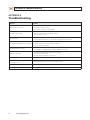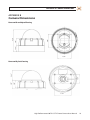
1
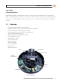
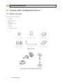
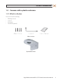
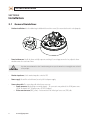
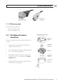
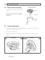
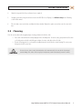
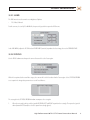
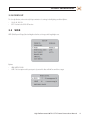
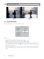
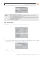
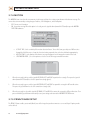
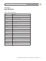
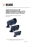
High Performance 690TVL Indoor/Outdoor Color CCTV Dome Camera User Manual Products: BLK-CWD208VH, BLK-CWD228VH Please read this manual before using your camera, and always follow the instructions for safety and proper use. Save this manual for future reference. BLK-690TVL_DomeCameras_CM 3/18/11 ! WARNING CAUTION Changes or modifications not expressly approved by the manufacturer could void the user’s authority to operate the equipment. To prevent electric shock and risk of fire hazards: Use a power source that is within specification only. Do NOT expose this appliance to rain or moisture. REGULATORY NOTICE This device complies with Part 15 of the FCC Rules. Operation is subject to the following two conditions: (1) This device may not cause harmful interference, and (2) This device must accept any interference received, including interference that may cause undesired operation. This equipment has been tested and found to comply with the limits for a Class A digital device, pursuant to Part 15 of the FCC Rules. These limits are designed to provide reasonable protection against harmful interference in a residential installation. This equipment generates, uses, and can radiate radio frequency energy and, if not installed and use in accordance with the instructions, may cause harmful interference to radio communications. Operation of this equipment in a residential area is likely to cause interference, in which case the user will be required to correct the interference at his own expense. LEGAL NOTICE DIGIOP products are designed to meet safety and performance standards with the use of specific DIGIOP authorized accessories. DIGIOP disclaims liability associated with the use of non-DIGIOP authorized accessories. The recording, transmission, or broadcast of any person’s voice without their consent or a court order is strictly prohibited by law. DIGIOP makes no representations concerning the legality of certain product applications such as the making, transmission, or recording of video and/or audio signals of others without their knowledge and/or consent. We encourage you to check and comply with all applicable local, state, and federal laws and regulations before engaging in any form of surveillance or any transmission of radio frequencies. Other trademarks and trade names may be used in this document to refer to either the entities claiming the marks and names or their products. DIGIOP, Inc. disclaims any proprietary interest in trademarks and trade names other than its own. No part of this document may be reproduced or distributed in any form or by any means without the express written permission of DIGIOP, Inc. © 2011 by DIGIOP, Inc. All Rights Reserved. 3850 Priority Way South Drive, Suite 200, Indianapolis, IN 46240 Sales/Support: 1.877.972.2522 ii www.digiop.com Table of Contents SECTION 1 SECTION 2 SECTION 3 SECTION 4 APPENDIX A APPENDIX B Precautions. . . . . . . . . . . . . . . . . . . . . . . . . . . . . . . . . . . . . . . . . . . . . . . . . . . . . . . . . . . . . . . . . . . . . . . . . . . . . . iv Introduction . . . . . . . . . . . . . . . . . . . . . . . . . . . . . . . . . . . . . . . . . . . . . . . . . . . . . . . . . . . . . . . . . . . . . . . . 1 1.1 Features. . . . . . . . . . . . . . . . . . . . . . . . . . . . . . . . . . . . . . . . . . . . . . . . . . . . . . . . . . . . . . . . . . . . . . . . . . . . 1 1.2 Cameras with a vandalproof enclosure . . . . . . . . . . . . . . . . . . . . . . . . . . . . . . . . . . . . . . . . . . . . . . . . . . 2 1.3 Cameras with a plastic enclosure . . . . . . . . . . . . . . . . . . . . . . . . . . . . . . . . . . . . . . . . . . . . . . . . . . . . . . . 3 Installation . . . . . . . . . . . . . . . . . . . . . . . . . . . . . . . . . . . . . . . . . . . . . . . . . . . . . . . . . . . . . . . . . . . . . . . . . 4 2.1 General Guidelines. . . . . . . . . . . . . . . . . . . . . . . . . . . . . . . . . . . . . . . . . . . . . . . . . . . . . . . . . . . . . . . . . . . 4 2.2 Vandalproof camera mounting. . . . . . . . . . . . . . . . . . . . . . . . . . . . . . . . . . . . . . . . . . . . . . . . . . . . . . . . . 5 2.3 Plastic camera mounting. . . . . . . . . . . . . . . . . . . . . . . . . . . . . . . . . . . . . . . . . . . . . . . . . . . . . . . . . . . . . . 6 2.4 Camera adjustments . . . . . . . . . . . . . . . . . . . . . . . . . . . . . . . . . . . . . . . . . . . . . . . . . . . . . . . . . . . . . . . . . 6 2.5 Cleaning. . . . . . . . . . . . . . . . . . . . . . . . . . . . . . . . . . . . . . . . . . . . . . . . . . . . . . . . . . . . . . . . . . . . . . . . . . . . 7 Software Setup. . . . . . . . . . . . . . . . . . . . . . . . . . . . . . . . . . . . . . . . . . . . . . . . . . . . . . . . . . . . . . . . . . . . . . 8 3.1 PRESETS . . . . . . . . . . . . . . . . . . . . . . . . . . . . . . . . . . . . . . . . . . . . . . . . . . . . . . . . . . . . . . . . . . . . . . . . . . . . 8 3.2 EXPOSURE... . . . . . . . . . . . . . . . . . . . . . . . . . . . . . . . . . . . . . . . . . . . . . . . . . . . . . . . . . . . . . . . . . . . . . . . . 8 3.3 WDR. . . . . . . . . . . . . . . . . . . . . . . . . . . . . . . . . . . . . . . . . . . . . . . . . . . . . . . . . . . . . . . . . . . . . . . . . . . . . . 11 3.4 WHITE BALANCE. . . . . . . . . . . . . . . . . . . . . . . . . . . . . . . . . . . . . . . . . . . . . . . . . . . . . . . . . . . . . . . . . . . . 12 3.5 DAY/NIGHT. . . . . . . . . . . . . . . . . . . . . . . . . . . . . . . . . . . . . . . . . . . . . . . . . . . . . . . . . . . . . . . . . . . . . . . . . 13 3.6 IMAGE ADJ... . . . . . . . . . . . . . . . . . . . . . . . . . . . . . . . . . . . . . . . . . . . . . . . . . . . . . . . . . . . . . . . . . . . . . . . 14 3.7 SPECIAL . . . . . . . . . . . . . . . . . . . . . . . . . . . . . . . . . . . . . . . . . . . . . . . . . . . . . . . . . . . . . . . . . . . . . . . . . . . 15 VIDEO STANDARD . . . . . . . . . . . . . . . . . . . . . . . . . . . . . . . . . . . . . . . . . . . . . . . . . . . . . . . . . . . . . . . . . . . . . . . . 17 Specifications . . . . . . . . . . . . . . . . . . . . . . . . . . . . . . . . . . . . . . . . . . . . . . . . . . . . . . . . . . . . . . . . . . . . . . 21 Troubleshooting. . . . . . . . . . . . . . . . . . . . . . . . . . . . . . . . . . . . . . . . . . . . . . . . . . . . . . . . . . . . . . . . . . . . 22 Camera Dimensions. . . . . . . . . . . . . . . . . . . . . . . . . . . . . . . . . . . . . . . . . . . . . . . . . . . . . . . . . . . . . . . . . 23 Camera with vandalproof housing. . . . . . . . . . . . . . . . . . . . . . . . . . . . . . . . . . . . . . . . . . . . . . . . . . . . . . . . . . 23 Camera with plastic housing. . . . . . . . . . . . . . . . . . . . . . . . . . . . . . . . . . . . . . . . . . . . . . . . . . . . . . . . . . . . . . . 23 High Performance 690TVL CCTV Dome Camera User Manual iii Precautions Do not install the camera in extreme temperature conditions. Use the camera in environments where temperature is between 14°F and 122°F. Ensure adequate ventilation. Do not install or use the camera in an environment where the humidity is high. It can degrade the image quality. Do not install the camera under unstable lighting conditions. Severe lighting changes or flicker can cause the camera to work improperly. Never use the camera close to a gas or oil leak. These chemicals can damage the camera. Do not drop the camera or subject it to physical shocks. These can cause malfunctions to occur. Never point the camera at intense light. Smear or blooming may occur, and it can damage the CCD. Do not expose an indoor camera to rain or spill liquids on it. If it gets wet, wipe it dry immediately. Liquids can contain minerals that corrode electronic components. Check the power source to ensure that it is within specifications before connecting it to the camera. iv www.digiop.com SECTION 1: INTRODUCTION SECTION 1 Introduction DIGIOP Black high performance indoor/outdoor CCTV dome cameras feature a very high resolution Pixim® 1/3” High Sensitivity Digital sensor providing 690 TVL (color), with a 2.8 – 11mm lens, a digital wide dynamic range, dual voltage range support (24 VAC, 12 VDC), and on-screen display (OSD) for control and setup. These cameras are available in either a durable plastic or vandalproof enclosure. 1.1 Features • • • • • • • • • • • • • • Wall or ceiling mounting through 3-axis camera bracket Vandalproof enclosures are IP67 rated and constructed with die-cast aluminum Flush/surface mountable using the supplied mount adaptor Safety strap keeps dome cover attached while making adjustments Pixim 1/3” High Sensitivity Digital Sensor High resolution 690 TV Lines Color, 800 TV Lines B&W Day or day/night operation (ICR) Vari-focal lens 2.8 – 11mm True wide dynamic range Digital noise reduction Privacy mask function On screen display (OSD) Motion detection High light compensation Lens Focus Lever Zoom Lever Joystick / OSD Control Tilt/Pan Bracket Video Out Internal Components High Performance 690TVL CCTV Dome Camera User Manual 1 SECTION 1: INTRODUCTION 1.2 Cameras with a vandalproof enclosure 1.2.1 What’s in the box Your camera includes the following: • • • • • • • Security tool Machine screws (4) Mounting cap Mounting screws (4) L-wrench User manual Dome bracket (optional) What’s in the box Optional dome bracket for wall and ceiling mounting 2 www.digiop.com SECTION 1: INTRODUCTION 1.3 Cameras with a plastic enclosure 1.3.1 What’s in the box Your camera includes the following: • • • • Mounting screws (4) L-wrench User manual Dome bracket (optional) What’s in the box Optional dome bracket High Performance 690TVL CCTV Dome Camera User Manual 3 SECTION 2: INSTALLATION SECTION 2 Installation 2.1 General Guidelines • Outdoor installations: Use the rubber rings included with the machine screws (4) to ensure that the unit is sealed properly. • Dome/window care: Handle the dome carefully to prevent scratching. If a scratch appears over the lens, adjust the dome window to move the scratch out of view. CAUTION Keep dome cover and camera lens clean. To avoid smearing, do not expose the camera lens to a strong light source such as the sun or spot lights. • Monitor impedance: Set the monitor impedance switch to 75Ω. • Power supply: To avoid fire or shock hazard, use only a UL® listed power supply. • Camera drop cable: The camera drop cable includes two connectors: —— Power connector (black with green terminal adapter) – The connector is non-polarized. Use AC24V power source (AC24V 1A adapter) or DC 12V power source (DC12V 1A adapter). —— Video coax connector (BNC, yellow) – for transmission of the video signal across coax (75Ω) cable. 4 www.digiop.com SECTION 2: INSTALLATION Power Connector Video Coax Connector 2.1.1 What you need To install the camera you will need: • • 12 VDC or 24 VAC power source Tools for mounting the camera 2.2 Vandalproof camera mounting The camera can be installed on a junction box or directly to a wall or ceiling. 1. Attach the surface mount bracket to the ceiling or wall using four (4) mounting screws. 2. Connect the dome base to the surface mount bracket using the screws with rubber rings provided. 3. Route the power and video cables to the camera location and attach them to the camera drop cable (see General guidelines above). 4. Attach the dome base to the surface mount bracket using the four machine screws provided. High Performance 690TVL CCTV Dome Camera User Manual 5 SECTION 2: INSTALLATION 2.3 Plastic camera mounting 1. Connect the dome base to the mounting surface using four (4) screws. 2. Route the power and video cables to the camera location and attach them to the camera drop cable (see General guidelines above). 2.4 Camera adjustments 1. Attach a video setup monitor to the yellow RCA (EXTRA VIDEO OUT) connector inside the camera assembly, or setup a remote monitor for viewing video from the camera. 2. Power on the camera and video monitor. 3. While observing video from the camera, adjust the pan/tilt swivel and PCB bracket to aim the camera in the preferred direction. Ceiling mounting 6 www.digiop.com Wall mounting SECTION 2: INSTALLATION 4. Adjust the image with the focus and zoom levers as required. 5. Configure your camera using the software menus in the OSD (On Screen Display). See Software Setup in the following section of this manual. 6. Place the dome cover over the base and adjust the dome window. Tighten the captive screws that secure the cover to the base. 2.5 Cleaning Clean the camera dome with an approved glass cleaning solution and a lint free cloth. —— —— Dust can be removed from the unit by wiping it with a soft damp cloth. To remove stains, gently rub the surface with a soft cloth moistened with a mild detergent solution, then rinse and dry it with a soft cloth. Remove all foreign particles, such as plastic or rubber materials, attached to the camera housing. These may cause damage to the surface over time. CAUTION Do not use benzene, thinner or other chemical products on the camera assembly; these may dissolve the paint and promote damage of the surfaces. Before using any chemical product, read the accompanying instructions carefully. High Performance 690TVL CCTV Dome Camera User Manual 7 SECTION 3: SOFTWARE SETUP SECTION 3 Software Setup Use the SETUP joystick on the PC board to navigate through the menu system. Press the joystick down (toward the PC board) to enter the SETUP menu or select an entry, rock the stick up or down to highlight an item in the list, and left or right display the option you want to select. The SETUP menu consists of a list of sub-menus or displays the option selected for a camera function. When sub-menus are available, the > symbol is shown before the selected row. Change the row by rocking the joystick to UP or DOWN 3.1 PRESETS Options (see the screen image above): • NORMAL / INDOOR / OUTDOOR 3.2 EXPOSURE.. Selecting EXPOSURE.. opens the EXPOSURE submenu. 8 www.digiop.com Change the option by rocking the joystick to RIGHT or LEFT SECTION 3: SOFTWARE SETUP 3.2.1 LENS The LENS menu is used to control screen brightness. Options: • DC / Video / Manual For this camera, select only DC or MANUAL, then press the joystick in to open the LENS menu. In the LENS MENU, adjust the DC GAIN an/or AI THRESHOLD (auto iris) to produce the best image, then select PREVIOUS PAGE. 3.2.2 FOCUS Use the FOCUS submenu to sharpen the camera focus and select the focus region. With the lens pointed at the surveillance target, the camera will set the focus based on the focus region. Select SET FOCUS REGION to set a spot in the image that you want to set as the focal distance. The rectangle in the SET FOCUS REGION window encompasses the set region. 1. When the rectangle is white, rock the joystick UP, DOWN, LEFT and RIGHT to position the rectangle. Then press the joystick down (toward the PC board) to select the expansion rectangle (green). High Performance 690TVL CCTV Dome Camera User Manual 9 SECTION 3: SOFTWARE SETUP 2. When the rectangle is green, rock the joystick UP, DOWN, LEFT and RIGHT to expand the rectangle in different directions. Then press the joystick down to select the contraction rectangle (red). 3. When the rectangle is red, rock the joystick UP, DOWN, LEFT and RIGHT to contract the rectangle in different directions. Then press and hold the joystick down momentarily to save your settings and return to the FOCUS DETECTOR menu. 3.2.3 EXPOSURE MODE Options: • 60i / 30p 3.2.4 AGC AGC (Automatic Gain Control) is used to automatically adjust the brightness. A higher AGC setting compensates for darker environments, but produces more noise in the image. Options: • • LOW / MIDDLE / HIGH OFF 3.2.5 DNR DNR (Digital Noise Reduction) reduces the level of background noise in low light conditions as the level of gain changes. Options: • • OFF LOW / MIDDLE / HIGH 3.2.6 HIGHLIGHT Highlight optimize the scene when high dynamic range lighting is detected. Options are: • • ON : Bright parts of the image are most visible OFF : dark parts of the image are most visible 3.2.7 COLOR ROLL Color Roll helps to control a detector that finds color fluorescent roll. Options: • • 10 LOW / MIDDLE / HIGH OFF www.digiop.com SECTION 3: SOFTWARE SETUP 3.2.8 SENS-UP The Sens-Up function, when activated, helps to maintain a clear image in dark lighting conditions. Options: • • 2X, 4X, 8X, 16X, 32X OFF : Deactivates the SENS-UP function 3.3 WDR WDR (Wide Dynamic Range) function brightens dark areas in images with large bright areas. Options: • • LOW / MIDDLE / HIGH USER : The User option enables you to precisely control the bias and limit for surveillance targets High Performance 690TVL CCTV Dome Camera User Manual 11 SECTION 3: SOFTWARE SETUP WDR Off WDR ON 3.4 WHITE BALANCE White Balance (WB) is used to correct screen colors for lighting conditions. Options are: • • • • • 12 ATW : The ATW mode continuously monitors the image and adjusts WB. INDOOR : Select this option when the color temperature is between 4000°K ~ 8500°K OUTDOOR : Select this option when the color temperature is between 2000°K ~ 11000°K AWB : To automatically set the white balance for the current luminance levels, point the camera at a sheet of white paper and press the Joystick down (toward the PC board). NOTE: If the environment changes, including the light source, the white balance will require re-adjustment. MANUAL : Select manual to fine-tune the white balance. To use this feature, set the white balance using the ATW or AWB mode, switch to MANUAL mode and fine-tune the white balance, then press SET (press the joystick toward the PC board (down)). www.digiop.com SECTION 3: SOFTWARE SETUP NOTE The White Balance function may not perform optimally: • • • When the color temperature of the image has a very high temperature range (e.g. clear sky, or sunset) When the ambient illumination of the subject is low. If the camera is pointed at a fluorescent light, or is installed in a place where illumination changes significantly, the white balance may become unstable. In these environments, select AWB mode. 3.5 DAY/NIGHT The DAY/NIGHT feature controls how the camera switches modes for different lighting conditions. Options: • AUTO : In this mode the camera engages an IR Cut-Filter that automatically changes to the appropriate settings for the lighting levels. To set up the switching time and switching speed for the AUTO mode, press SET. • COLOR : The picture is displayed in color. B/W : The picture is always displayed in black and white. • High Performance 690TVL CCTV Dome Camera User Manual 13 SECTION 3: SOFTWARE SETUP 3.6 IMAGE ADJ.. Select IMAGE ADJ.. to open the IMAGE submenu. 3.6.1 FREEZE Freeze creates a still image of the screen. Options: • OFF / ON 3.6.2 FLIP Flip allows you to reverse the image horizontally, vertically, or both. Options: • 14 OFF / HORIZ / VERT / BOTH www.digiop.com SECTION 3: SOFTWARE SETUP FLIP: OFF FLIP: HORIZ FLIP: VERT FLIP: BOTH 3.6.3 SHARPNESS The outline of the video image becomes more distinct as the level of SHARPNESS setting increases. If the SHARPNESS is set too high, noise may appear. Adjustment range: -8 ~ 8 3.6.4 COLOR GAIN Used to control the color level in the image. Adjustment range: -8 ~ 8 3.6.5 GAMMA Used to adjust the gamma level. Adjustment range: 25 ~ 100 3.7 SPECIAL The SPECIAL submenu includes several features that add to or subtract from parts of the image. High Performance 690TVL CCTV Dome Camera User Manual 15 SECTION 3: SOFTWARE SETUP Select SPECIAL to open the submenu. 3.7.1 CAMERA ID You can enter a unique name for the respective camera. The maximum length of the ID is ten characters. Options: • • OFF : Camera ID is not displayed. ON : Camera ID is displayed. After selecting ON, the camera ID submenu opens. To set the camera ID name, highlight the ID row, then press SET. The first character in the name field will blink. Rock the joystick left or right to change the character. Press SET to select the character and move to the next character. Repeat until the complete ID name is shown. 16 www.digiop.com SECTION 3: SOFTWARE SETUP Rock the joystick to DOWN to highlight the POSITION line. Rock the joystick to LEFT or RIGHT to change the position option. Options include: —— UP-LEFT / UP-CENTER / UP-RIGHT / DOWN-LEFT / DOWN-RIGHT 3.7.2 VIDEO I/O The VIDEO I/O submenu offers several options including VIDEO STANDARD, VIDEO OUT, DIGITAL OUT, 656 OSD, and FIELD ORDER. The VIDEO OUT, DIGITAL OUT, 656 OSD, and FIELD ORDER adjustments are for factory use only and should not be changed. VIDEO STANDARD The VIDEO STANDARD submenu is used to setup the video signal transmitted to the monitoring equipment. Options: • VIDEO SELECT : NTSC / PAL. This option must remain as NTSC. Do not change this option. VIDEO LEVEL / SYNC LVL / BURST LVL : Change these settings as necessary to produce the optimal video signal transmitted to the monitoring equipment. These levels are set at the factory and usually do not need adjustment. • COLOR BAR : ON / OFF : Turns color bars on or off for use during video signal adjustments. • 3.7.3 DZOOM Digital P/T/Z are used to create a zoom lens effect. Options: • • ON : Use the DZOOM feature. Selecting ON opens the DZOOM submenu —— Zoom factor (1x to 8x). To use Pan and Tilt, the zoom factor must be greater than 1x. —— Pan factor (±100%, center of image can be moved to left and right edges of screen) —— Tilt factor (±100%, center of image can be moved to top and bottom edges of screen) OFF : DZOOM is not in use. High Performance 690TVL CCTV Dome Camera User Manual 17 SECTION 3: SOFTWARE SETUP 3.7.4 MOTION The MOTION feature is used to detect movements in the image and alert the security system observer with a banner message. The camera detects movement by sensing changes of outlines, level of brightness, and color. Options: • • OFF : Do not sense for motion. ON : Use motion sensing. When this option is selected, press the joystick down (toward the PC board) to open the MOTION DETECTION submenu. —— —— —— ACTIVITY THR : Set the sensitivity of the motion detection feature. To use this feature, pass objects of different sizes through the field of view to see how the detection circuitry responds, then set the threshold value appropriately. MESSAGE TIME : Set the duration of the banner message that appears on the image when motion is detected. SETUP MOTION ZONE.. ; Select this option to select the area of the image to monitor for motion. 1. When the rectangle is white, rock the joystick UP, DOWN, LEFT and RIGHT to position the rectangle. Then press the joystick down (toward the PC board) to select the expansion rectangle (green). 2. When the rectangle is green, rock the joystick UP, DOWN, LEFT and RIGHT to expand the rectangle in different directions. Then press the joystick down to select the contraction rectangle (red). 3. When the rectangle is red, rock the joystick UP, DOWN, LEFT and RIGHT to contract the rectangle in different directions. Then press and hold the joystick down momentarily to save your settings and return to the MOTION DETECTION menu. 3.7.5 PRIVACY MASK SETUP The PRIVACY feature enables you to mask (block) areas of the image that you do not want to see or record. Up to 12 privacy masks can be defined. 18 www.digiop.com SECTION 3: SOFTWARE SETUP Options: • PRIVACY MASK : OFF / ON : Select OFF to disable privacy masking. When ON is selected, the ENABLE MASKS submenu opens. In the ENABLE MASKS window, highlight the mask number you want to use, then rock the joystick left or right to select ON. Press the joystick down (toward the PC board) to open the mask position window. In the position window rock the joystick to UP, DOWN, LEFT or RIGHT to move the mask position up, down, right or left. When the mask covers an area you want to block, press the joystick down (toward the PC board) to fix that position and return to the ENABLE MASKS window. Repeat this procedure with a other masks to block other areas of the image. In the ENABLE MASKS window, select PREV. to return to the previous window. • MASK COLOR : Rock the joystick LEFT or RIGHT to change the color of the mask on the image. Options: WHITE / BLACK / RED. High Performance 690TVL CCTV Dome Camera User Manual 19 SECTION 3: SOFTWARE SETUP 3.7.6 SYNC SYNC sets the video synchronization mode. Options: • • INT : Internal synchronization LL.. (EXTERNAL LINELOCK) : The line-lock feature enables you to synchronize the video signal between cameras through adjusting the video phase of the camera signal. After the phase is adjusted, press the joystick down (toward the PC board) to save the setting. 3.7.7 RS485 SETUP.. The RS485 SETUP feature is not used with this camera model. 3.7.8 RESET This feature is used to reset the RS485 settings. It is not used with this camera model 20 www.digiop.com SECTION 4: SPECIFICATIONS SECTION 4 Specifications Table 1.Item Specifications Item Specification Image Sensor Piixim 1/3” High Sensitivity Digital Sensor Effective Pixels 758 (H) x 540 (V) Dynamic Range 120dB (maximum), 102dB (typical) Horizontal Resolution 690TVL effective (color), 800TVL effective (B/W) Min. Illumination 0.1 Lux (Color), 0.01 Lux (B/W) Day & Night Auto / Color / B/W White Balance Auto / AWB / Indoor / Outdoor / Manual WB Range 2000°K ~ 11,000°K Shutter Speed up to 1/30, 720 sec Sens-up Auto / Off (selectable x2 ~ x32) Privacy Masking 12 zones Remote Control RS-485 AGC Low / Auto / High / Off Image Flip Horizontal and vertical Camera ID On / Off S/N Ratio More than 50dB Video Output Composite video output 75 Ω terminated OSD Built in Sync. System Internal / line lock Power Consumption 240mA (24 VAC) / 360mA (DC12V) Operating Humidity 30% ~ 90% RH Operating Temp. 50°F ~ 122°F (10°C ~ 50°) High Performance 690TVL CCTV Dome Camera User Manual 21 APPENDIX A: TROUBLESHOOTING APPENDIX A Troubleshooting Problem Solution Nothing appears on the screen. - Check the power connections. - Check the video cable connections. - Ensure that the lens mode is set to DC (VIDEO). The video image is not clear. - Clean the lens with a soft, clean cloth. - Adjust the monitor screen for room lighting conditions. - Move the camera if necessary. The screen is dark. - Adjust the contrast feature of the monitor. - If you have an intermediate device, set the 75Ω /Hi-Z properly, and check the terminals. The MOTION DETECTION function is not working - Is “MOTION DETECTION” mode turned on? - Is the MD Sensitivity set too low? Increase the sensitivity. - Check the setting of the MD AREA. The WDR function is not working - Is the WDR level too low? - Is the AE Mode set to MANUAL? WDR is disabled in MANUAL exposure mode. Colors are not quite right. - Is the camera facing directly into sunlight or fluorescent light? - Is the auto iris lens is being used? - Check the connection of the lens connector cable. The Day&Night function doesn’t work. - Is the AGC (EXPOSURE menu) set to OFF? The Auto Day&Night Function doesn’t work if the AGC is OFF. The camera is not working properly and the camera surface is hot. Check that an appropriate power source is connected to the camera. Color is not correct. Check the WHITE BAL settings in the SETUP menu. The screen flickers continually. Check that the camera is not pointing at a bright object. 22 www.digiop.com APPENDIX B: CAMERA DIMENSIONS APPENDIX B Camera Dimensions 2.95" 4.96" 1.38" 1.61" Camera with vandalproof housing 2.95" 1.52" 1.75" 1.81" 2.09" Camera with plastic housing 3.29" High Performance 690TVL CCTV Dome Camera User Manual 23