1
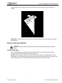
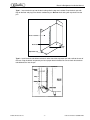
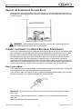
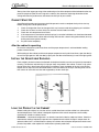
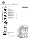
Reach-In Refrigerator Installation Manual
INSTALLATION MANUAL
Reach-In Refrigerators
COR20RRTM, COR22RRTM, COR40RRTMD,
COR48RRTMD, COR74RRTMT
CAUTION - Only trained and certified electrical, plumbing and refrigeration technicians should
service this unit. ALL WIRING AND PLUMBING MUST CONFORM TO NATIONAL AND LOCAL
CODES.
CHECK FOR SHIPPING DAMAGE
Prior to leaving the factory, each cabinet is thoroughly inspected and performance tested up to 12 hours
to assure proper operating temperatures.
Check the crate thoroughly for signs of shipping damage.
If signs of shipping damage are present:
If the damage is severe and obvious, refuse the shipment. The carrier will return the cabinet to the
factory. Call the factory immediately, noting that the shipment was refused and we’ll ship a replacement
cabinet and handle the freight claim.
If no obvious crate damage is present, within two hours of receiving the cabinet from the carrier, remove
the front and side panels to inspect for concealed damage.
1.
2.
If concealed damage is found, call the carrier immediately, save all crating materials, and file the
necessary freight claim with the carrier.
If no concealed damage is present, reassemble the crate to protect the cabinet for final location
delivery.
WHERE TO LOCATE THE CABINET
•
Place the cabinet on a surface strong enough to support the combined weight of the cabinet and the
product load and solid enough to prevent vibration. Guideline: estimate 35 pounds per cubic foot of
storage space.
•
Locate the cabinet on a level surface. Minor unevenness can be compensated for by the adjustable
legs or shimming the base or casters.
•
Place the cabinet in areas where the ambient room temperatures are between 50oF and 90oF.
Excessive heat will affect performance and may cause condensation.
•
Locate the cabinet in well-ventilated areas. The cabinet should be protected from heat sources and
direct sun’s rays. If the cabinet is in front of a window, provide an awning or shade to shield the cabinet
from direct sunlight.
Release Date: June 16, 2004
© 2004, IMI Cornelius Inc.
www.cornelius.com
-1-
Revision: A
Publication Number: 630460252INS
Reach-In Refrigerator Installation Manual
•
If the condensing unit is located in the bottom of the cabinet, leave an air space of at least 3” in back
of the cabinet for venting the hot air from the unit compartments.
3"
Air flow to dissipate
condenser heat
Rear of cabinet
Base
Floor
FIGURE 1
•
If the condensing unit is located on the top of the cabinet, it is not necessary to leave space behind
the cabinet. However, 12” of clearance is required from the top of the cabinet to the ceiling.
•
Measure all doorways and passages before moving the cabinet to its final location. To pass through
low door openings, first remove the shelves shipped inside the cabinet and lay one- and two-section
upright cases on end.
CAUTION - Lay the cabinet on pads or thick blankets to avoid damage to the cabinet finish. After the
cabinet is set upright, check for oil leaks in the compressor compartment. If you find oil leaks, call a
qualified service person before operating the unit. If no oil leaks are found, wait 1/2 hour before operating
the unit.
REMOVE THE CRATE AND SKID
Remove the crate carefully to prevent damage to the exterior surfaces of the cabinet. The cabinet is
bolted to a wooden skid with four hex-head bolts. After the skid is removed, always use a dolly to move
the cabinet to prevent damage to the cabinet bottom or the floor.
Cabinet
Wooden
skid
1/2 13 hex bolt
FIGURE 2
REMOVE THE DOOR AND HINGES
On upright cases, if the doorway or passage way is too narrow, the doors and hinges can be removed.
Open the door 45 degrees and lift the door up and off the hinge pin. Use a phillips head screwdriver to
remove the hinges. When re-assembling the door and hinges, tighten the hinge screws slightly and
rehang the door. Check to be sure the door is properly aligned. Use a block of wood and a hammer to tap
Publication Number: 630460252INS
-2-
© 2004, IMI Cornelius Inc.
Reach-In Refrigerator Installation Manual
the hinge until the door is properly aligned. Then tighten the hinge screws to prevent the door from
sagging.
45°
455
Open door 45 °
Open door
and
liftand lift
455
Hinge
FIGURE 3
IMPORTANT - Level the cabinet from front to back and from end to end to insure proper drainage and
door operation.
INSTALL LEGS AND CASTERS
CAUTION - Top mounted units are top heavy. Be careful when mounting legs or moving the
cabinet.
To install the legs
Heavy, adjustable legs are provided with all top mounted cabinets so the cabinet may be leveled
accurately and to allow room to clean beneath the cabinet.
Do not lay the cabinet down either on its back or sides. Always keep it in an upright position. Tilt the
cabinet back just far enough to fit the front legs and place a block of wood or some similar support under
it until both front legs are in. Then tilt the cabinet forward enough to install the rear legs.
© 2004, IMI Cornelius Inc.
-3-
Publication Number: 630460252INS
Reach-In Refrigerator Installation Manual
After the legs are installed, level the cabinet by using the adjustable portion of the legs as needed. This is
very important to insure proper draining and door operation.
FIGURE 4
To install casters
Casters are supplied as optional equipment. To install the casters, follow the directions for installing legs .
INSTALL THE CONDENSATE DISPOSAL SYSTEM
Sealant
FIGURE 5
WARNING - The condensate disposal system is designed to dispose of the water from the
evaporator only under normal operating conditions. When cases are used with ice or when
additional water is generated by the case through abnormal usage or ambient conditions, a floor
drain or similar arrangement might be required.
Top mounted units
Depending on the model ordered, an electric condensate evaporator pan is available to dispose of
condensate water. The electric evaporator pan plugs into a 115 V 15 AMP line which should be a
separate line from the cabinet power supply.
Publication Number: 630460252INS
-4-
© 2004, IMI Cornelius Inc.
Reach-In Refrigerator Installation Manual
Type 1 - Insert the drain trap into the drain tubing after the legs are installed. Place the drain pan with
legs on the floor and plug in the electric condensate pan. Be sure drain tubing with trap drains into the
pan.
Rear of cabinet
Drain tube
Drain
trap
Adjustable legs
FIGURE 6
Type 2 - Install the drain tube elbow to the drain tube. Attach the evaporator pan and cradle to the rear of
the case. Plug the electric evaporator pan into a proper electrical outlet. Be sure to check that the drain
tube elbow drains into the pan.
FIGURE 7
© 2004, IMI Cornelius Inc.
-5-
Publication Number: 630460252INS
Reach-In Refrigerator Installation Manual
RELEASE THE COMPRESSOR TIE-DOWN BOLTS
Check the compressor compartment to see if your cabinet has a spring-mounted compressor which is
bolted down to avoid shipping damage. Loosen the tie-down nuts until the compressor is loose and rides
free on the springs.
FIGURE 8
WARNING - Failure to loosen these bolts will result in excess noise and vibration which will
damage the refrigeration system and void your warranty.
CONNECT THE CABINET TO A PROPER ELECTRICAL POWER SUPPLY
Be sure that a qualified electrician or refrigeration service person checks to see that your building’s wire
size is adequate to carry the load of the cabinet being installed and the circuit breaker or fuse is a timedelay type. Each refrigerator should be connected to its own circuit for best operation and to avoid
possible product loss due to other defective electrical appliances. The cabinet comes with an on/off
power switch located in the unit compartment in compliance with U.L. requirements. Consult the
specification sheet and wiring diagram for details about your model cabinet. Consult the local electrical
codes and U.L. for additional requirements. A 5% deviation from the specified electrical requirements will
result in poor performance, shorten the life of the electrical components, and void your warranty.
Plug in your cabinet
If your cabinet is rated at 12 amps or below, a standard three-prong grounding power plug is provided. Be
sure to plug directly into a properly-grounded three-prong receptacle.
If your cabinet is rated at 13 amps to 15 amps, a special three-prong grounding power plug is provided.
Be sure to plug directly into a properly-grounded three-prong receptacle.
FIGURE 9
IMPORTANT - Do not, under any circumstances, cut or remove the round grounding prong from the
power plug.
If your cabinet is rated at 16 amps or above, an electrician must run the proper size wiring to the
power box.
See the enclosed electrical diagram for details.
Publication Number: 630460252INS
-6-
© 2004, IMI Cornelius Inc.
Reach-In Refrigerator Installation Manual
Always check the amperage rating of the condensing unit and the complete cabinet to determine the size
power line required. (See the serial tag on the cabinet.) Any excessive amperage drawn due to low
voltage will affect the performance and shorten the life span of your cabinet.
CABINET START UP
A qualified refrigeration service person should be present to make a complete check prior to start-up.
Before turning on the on/off power switch:
1.
2.
3.
4.
5.
6.
Check all refrigeration lines for damage which may have occurred during shipping or installation.
Check that all wires are clear of the fans and that the fan blades turn freely.
Check the unit compartment for oil leaks.
If the compressor is mounted on external springs, be sure the hold-down nuts have been loosened.
Clean the interior of the cabinet with mild soap and rinse with a warm baking soda solution (one cup
baking soda to one gallon of water).
Dry the interior completely.
After the cabinet is operating
Be sure the compressor cycles three times and the proper temperature is achieved before loading
product into the cabinet.
While waiting for the cabinet to achieve the proper temperature and cycles three times, open the door(s)
to see if the light goes on. With the door(s) open, push the door switch button(s) to see if the lights go out.
INSTALL THE ADJUSTABLE SHELVING
Each cabinet’s pilaster has been installed with knurled-head machine screws and are easily removed for
cleaning. The shelves and shelf clips (4 clips per shelf) are packed in the cabinet. To insert a clip, place
the top of the clip in the pilaster while pushing in and down. Insert the bottom of the clip in the pilaster.
Repeat until all clips are in the desired locations. Place the shelves on the clips, checking to be sure all
four corners of each shelf are level and supported by the four shelf clips.
FIGURE 10
LOAD THE PRODUCT IN THE CABINET
Before loading the cabinet, be sure the unit has cycled three times and the cabinet has achieved the
desired temperature. Each cabinet is designed to perform within certain temperature and humidity
requirements, based on ambient factors.
Remember - a commercial refrigerator is an electrical mechanical device subject to failures. Check the
thermometer readings frequently to prevent loss of product due to radical changes in temperature. An
optional audio alarm is available from the factory for cabinets where frequent temperature checks aren’t
practical or product value requires this notification to prevent product loss.
© 2004, IMI Cornelius Inc.
-7-
Publication Number: 630460252INS
Reach-In Refrigerator Installation Manual
WIRING DIAGRAMS
COR20RRTM
WHITE
COND. UNIT
SPEAR LINE
WHITE
GREEN
BLACK
BLACK
JUNCTION
BOX
WHITE
WHITE
BLACK
WHITE
LIGHT
BULB
BLACK
BLACK
WHITE
BLACK
RED
BLACK
BLACK
PERIMETER HEATER
WHITE
TEMP. CONTROL
WHITE
BLACK
FAN MOTOR
BLACK
RED
RED
PUSH
BUTTOM
FIGURE 11
Publication Number: 630460252INS
-8-
© 2004, IMI Cornelius Inc.
Reach-In Refrigerator Installation Manual
COR22RRTM
BLACK
WHITE
BLACK
WHITE
GREY
RED
BLACK
WHITE
GREY
RED
BLACK
WHITE
HEATER
SWITCH
MULLION/CANOPY
CONNECTION
POWER
DOOR
AJAR
G
B
W
GREEN
WHITE
BLACK
GREEN
B
PUSH
BUTTOM
LIGHT
BULB
FEED
ELECT. BOX
4X4
WHITE
BLACK
GREEN
HEATERS - FASCIA
SWITCH
EVAP.
PAN
COND.
UNIT
WHITE
BLACK
GREEN
RED
WHITE
WHITE
BLACK
RED
FAN MOTOR
WHITE
BLACK
CONTROL
RED
BAFFLE
CONNECTION
BLACK
FIGURE 12
© 2004, IMI Cornelius Inc.
-9-
Publication Number: 630460252INS
Reach-In Refrigerator Installation Manual
COR40RRTMD
WHITE
COND. UNIT
SPEAR LINE
WHITE
GREEN
BLACK
BLACK
JUNCTION
BOX
WHITE
WHITE
BLACK
WHITE
PUSH
BUTTOM
LIGHT
BULB
BLACK
BLACK
BLACK
WHITE
BLACK
BLACK
RED
BLACK
BLACK
PERIMETER HEATER
WHITE
TEMP. CONTROL
WHITE
BLACK
FAN MOTOR
BLACK
RED
RED
PUSH
BUTTOM
FIGURE 13
Publication Number: 630460252INS
- 10 -
© 2004, IMI Cornelius Inc.
Reach-In Refrigerator Installation Manual
COR48RRTMD
BLACK
WHITE
BLACK
WHITE
GREY
RED
BLACK
WHITE
GREY
RED
BLACK
WHITE
HEATER
SWITCH
MULLION/CANOPY
CONNECTION
POWER
BLACK
WHITE
BLACK
WHITE
B
G
PUSH
BUTTOM
G
B
W
B
GREEN
WHITE
BLACK
GREEN
MULLION HEATERS
DOOR
AJAR
PUSH
BUTTOM
LIGHT
BULB
FEED
ELECT. BOX
4X4
WHITE
BLACK
GREEN
HEATERS - FASCIA
SWITCH
EVAP.
PAN
COND.
UNIT
WHITE
BLACK
GREEN
RED
WHITE
WHITE
BLACK
RED
FAN MOTOR
WHITE
BLACK
CONTROL
RED
BAFFLE
CONNECTION
BLACK
FIGURE 14
© 2004, IMI Cornelius Inc.
- 11 -
Publication Number: 630460252INS
Reach-In Refrigerator Installation Manual
COR74RRTMT
BLACK
WHITE
BLACK
WHITE
GREY
RED
BLACK
WHITE
GREY
RED
BLACK
WHITE
HEATER
SWITCH
MULLION/CANOPY
CONNECTION
POWER
BLACK
WHITE
BLACK
WHITE
B
G
PUSH
BUTTOM
G
B
LIGHT
BULB
W
B
PUSH
BUTTOM
G
B
W
B
GREEN
WHITE
BLACK
GREEN
MULLION HEATERS
MULLION HEATERS
DOOR
AJAR
PUSH
BUTTOM
LIGHT
BULB
FEED
ELECT. BOX
4X4
WHITE
BLACK
GREEN
HEATERS - FASCIA
SWITCH
EVAP.
PAN
COND.
UNIT
WHITE
BLACK
GREEN
RED
WHITE
WHITE
BLACK
RED
FAN MOTOR
WHITE
BLACK
CONTROL
RED
BAFFLE
CONNECTION
BLACK
FIGURE 15
Publication Number: 630460252INS
- 12 -
© 2004, IMI Cornelius Inc.