1
KB2LJJ Radio Mods Database and Manuals
Mods TM-733
www.r6-ru4montesecchieta.it
IZ5CCV
TM-733 Japonise version Cross Band Repeating
Cross band repeat isn't documented but comes ready from the factory.
To enable cross band repeat from the front panel, first select a band by pressing BAND SELECT. Then, change the control to
the other band by hitting [CONT SEL]. Next, press [F] for one second, then the "X" button (far right side). Decimals will
appear between the Kilohertz digits, and the "ON" indicator will light momentarily. The microphone sequence to enable cross
band repeat while in remote control mode is "DC".
The transmitter hang time can be toggled between 500ms to 0ms by turning on the radio with [LOW] pressed. They also
recommend enabling the Time-out Timer, for obvious reasons.
TM-733 can also be used as a "one-way" cross-band repeater.
For example, if you can receive a distant repeater with your HT, but have difficulty getting into it, you can use the TM-733 to
boost your transmitted signal. To set this up, just omit the part where you "change the control to the other band by pressing
[CONT SEL]." Doing this will setup the TM-733 to repeat your signal to the other band, but will not retransmit the distant
station back to you. If this sounds ambiguous, play around with it a little and it will begin to make sense.
TM-733 with 2 antenna-sockets
Note that the
As I started to use the TM733E on my 3 bander COMET 901 , I had to modify my transceiver. As I think some off you use a 3 way splitter to
connect several transceivers at the same time there was a problem,I could not use the 23cm band and the splitter anymore sinds the TM733E
came with only one antenna socket (mixed VHF and UHF).
After looking around in different shops, I was unable to find a splitter that had the UHF and VHF together on one socket and the 23cm band on
another.
So I decided to have a look at the schematics off the TM733E and noticed the US version has 2 antenna sockets.
Modifying the rig is very simple:
Make a second antenna cable with PL259 socket or get it at your local Kenwood dealer (some 15$) (same cable as on the other mobile dual
banders ...TM701 etc.)Open both sides off the transceiver.
Take off the plastic cover off the spare hole at the back.
Insert and solder the new antenna cable.
Take away the connection (one big pin) from the VHF to the UHF pc-board with a good solderpump.
Your rig has now 2 antenna-inputs ,one for VHF ,one for UHF.
This mod. is also interesting for those who often use the CROSSBANDREPEATER, sinds you can now connect a vertical to the 70cm tx and a
beam to the 2m part or the other way round.
Good luck with the modification and ...
have as much fun with the TM733E as i do !
73 de Jan ON1BJC @ ON4ABG
TM733 and 9k6 Bps
As I first started to use the TM733E on 9600Bps ,it didn't work very well.
Rx 9600Bps was no problem but the TX-side was poor in transmission-speed.
http://www.kb2ljj.com/data/kenwood/TM-733.htm (1 di 9)30/08/2009 18.42.07
KB2LJJ Radio Mods Database and Manuals
After having a look at the SERVICE MANUAL i discovered that the audiosignal from the G3RUH should at least be 2 Volts PEP.
This information is not in the original manual delivered with the TM733E.
Txdelay starts at 200mS and combination nr 9 (strap settings G3RUH) seems to be the best to get minimum errors ...
Hoping to set some off you on the right track now...
73 de Jan ON1BJC @ ON4ABG
TTM733 & 9K6
Well John, i'm sorry i have to say this but the Kenwood TM733 is definitely NOT suited for 9600bd operation. It has several serious design
bugs.
●
●
PLL modulation, thereby giving very bad Bit Error Rate figures because of the bad lf response of the modulation circuits. At 64 Hz,
there is a 4.5 dB rise.
Slow tx<>rx switching. The TM733 needs 100-150 milliseconds to turn around. If your opponent (satellite or earth station) is faster
with replying you keep on missing his first packet.
These problems are very common in the current generation "9600bd ready" transceivers. The Icom IC281/481, Yeasu 5100 and many others
suffer from these problems.
The Kenwood TM733 has another design bug :
●
If you try to make more than about 2.5 KHz deviation via the data port, the modulation gets very distorded. This is not easy noticable,
since 9k6 modulation sounds like noise, and distorded 9k6 also sounds as noise.. This problem is seen at more than one TM733,
throughout Europe.
I sure hope you can send this thing back and get your money back, John.
TM-733E MOD 9k6 English
After I bought a Kenwood TM-733E transceiver for packet radio I was very disappointed about the bad modulation in the 9600 baud packet
mode on the 430 mc band. For many digipeaters the tranceiver produced insufficient fm deviation. If you increase the modulation voltage you
will get a strong distortion of your signal. The german Kenwood office was unable or unwilling to fix this problem.
After some experiments I found the following solution for my transceiver:
Increase the internal packet radio modulation signal for the 70cm band by reducing the value of a SMD resistor. The resistor lives on the TXRX Unit/Control board (X57-436X-XX)(C/4). The resistor is named R536 and it has a value of 56 kOhm. I reduced itïs value by soldering an
additional SMD resistor of 30 kOhm on itïs top.
The two resistors form a new value of 19 kOhm. This will increase the modulation voltage for the PLL unit and you need less input signal on
the data input at the socket J402. My tranceiver makes now a deviation of 3.5 kHz with 1V/pp instead of 2.2 kHz with 2V/pp before.
There is less distortion than before. Concerning 9k6 packet radio the TM-733E has a bad frequency characteristic. It can be fixed with a
suitable selection of the modem transmission filter. The following selection was the best for my TNC2H:
0 0 1 1 (switches 5 to 8, 1 = up, 0 = down).
Please note:
I am not responsible for your modifications.
You will do it at your own risk!
You need:
15 to 20 minutes time, a magnifying glass a screw driver (X), a needle type soldering iron and a SMD resistor of round about 30 kOhm
1.
2.
3.
4.
5.
6.
7.
Remove the top cover ( 4 screws )
Remove the bottom cover ( 4 screws )
Remove the front panel ( no screws! )
Remove the plastic front cover ( 6 plastic snappers )
Disconnect the two flat cables on the front board ( shift the bolts )
Remove the front board ( 2 screws )
Find the SMD resistor named R536 ( the print on the resistor reads 563, it is located on the back side of the front board between the
two flat cable sockets, use a magnifying glass! )
8. Solder the 30 KOhm SMD resistor on top of the R536
9. Reassemble the other way round ( good luck ! )
When the modification is done you have to setup your modem (modulation voltage and filter selection) again.
Concerning Kenwoods bad support in germany my next packet radio tranceiver will be from a different manufacturer.
http://www.kb2ljj.com/data/kenwood/TM-733.htm (2 di 9)30/08/2009 18.42.07
KB2LJJ Radio Mods Database and Manuals
Please send me a message with your results. Good success!
vy 73 Norbert DC6BC @ DB0IZ.#NRW.DEU.EU
MODS OF KENWOOD TM-733 for Japanese version
Maybe there are some difference for USA , EU and another vartion. So please use caution.
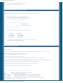
1. Remove the control panel. You can find CPU board.
2. Remove 2 screws on this board. Then turn insde out this board.
3. You can find a chip that printed [ 000 ] on this board.
--------------------------------------I
xx
I
xx meams [ 000 ]
I O
O I
O means hole of screw
I
I
--------------------------------------4. After remove this chip [ 000 ] , you can recieve as ffollows.
on 144MHz
118-173MHz
130-173MHz
300-469MHz
on 430MHz
118-173MHz
300-469MHz
800-900MHz
On 144MHz side , press [ MHz ] key more than 1 sec. , change mode for AM.
On 430MHz side , change band for 800Mhz.
TM-733A Quick Reference Guide
Assembly Mode Test
In the TM-733 Service Manual, it describes a test mode that I haven't seen mentioned anywhere else. So, here's the scoop:
Entering Assembly Mode: [CALL] + [MUTE] + [Power On]
All LCD segments should come on. (To exit, power off.)
Press the [VFO] key. *This must always be done first*
The serial port is checked and "F" with "80" on the display indicates test passed. "1" or "2" means failure.
Different keys now show different displays, with [LOW], [SHIFT], [TONE], and [REV] also adjusting the backlight intensity.
Set the dials to minimum, then press the [MR] key. Each of the dials shows the digitized level.
This looks useful for checking all the keys and dials when you suspect a bad connection.
Kenwood TM-733A Quick Reference Guide by Brad Killebrew N5LJV
----------------------------------------------------------------------------[#]
PRESS A NUMBER, NOT THE POUND SIGN.
[KEY]
PRESS AND RELEASE [KEY]
[KEY1]+[KEY2]
PRESS AND HOLD [KEY1] DOWN, THEN PRESS [KEY2]
[KEY1],[KEY2]
PRESS [KEY1] MOMENTARILY, THEN PRESS [KEY2]
[KEY]+[PWR]
WITH POWER OFF, PRESS AND HOLD [KEY] THEN HIT [PWR]
[KEY1]+[KEY2]+[PWR] YOU GET THE IDEA.
http://www.kb2ljj.com/data/kenwood/TM-733.htm (3 di 9)30/08/2009 18.42.07
KB2LJJ Radio Mods Database and Manuals
[F] (1s)
[KEY] (1s)
[F],[KEY] (1s)
PRESS AND HOLD [F] FOR ONE SECOND. "F" THEN BLINKS.
PRESS AND HOLD [KEY] FOR ONE SEOND.
PRESS [F] MOMENTARILY, THEN PRESS [KEY] FOR ONE SEC.
----------------------------------------------------------------------------The following entries are in alphabetical order.
1 MHZ/10 MHZ TUNING TOGGLE
[VFO],[F]+[MHZ]
ADVNACED INTERCEPT POINT (AIP)
[F]+[A.B.C.]
ALL LOCK
[F],[MHZ],[PWR],[F]+[PWR]
AM/FM MODE
[MHZ] (1s)
AUTO DIMMER CHANGE
[F]+[LOW]+[PWR]
AUTOMATIC BAND CHANGE (A.B.C.)
[F],[A.B.C.]
AUTOMATIC OFFET (CANCELLING)
[VFO]+[REV]+[PWR]
AUTOMATIC POWER OFF (APO)
[F] (1s),[MHZ]
AUTOMATIC SIMPLEX CHECKER
[REV] (1s)
AUTOMATIC SQUELCH
[MHZ] + [PWR]
AUTOMATIC TONE FREQUENCY ID
[TONE] (1s)
BAND SCAN
[VFO] (1s)
BEEP LOUDNESS
[F] (1s),[BEEP]
BLANKING A BAND DISPLAY
[F] (1s), [BAND SEL]
CALL CHANNEL CHANGING (ODD SPLIT)
(RX FR),[F],[C.IN] (1s),(TX FR)[CALL]
CALL CHANNEL CHANGING (SIMPLEX,DUPLEX) [F],[C.IN]
CALL CHANNEL RECALLING
[CALL]
CALL/MEMORY SCAN
[MR],[CALL] (1s)
CALL/VFO SCAN
[VFO],[CALL] (1s)
CANCELLING AUTOMATIC OFFET
[VFO]+[REV]+[PWR]
CHANGING CALL CHANNEL (ODD SPLIT)
(RX FR),[F],[C.IN] (1s),(TX FR)[CALL]
CHANGING CALL CHANNEL (SIMPLEX,DUPLEX) [F],[C.IN]
CHANNEL DISPLAY FUNCTION
[REV]+[PRW]
CONFIRMING PROGRAMMABLE LIMITS
[F]+[VFO],(L.SHOWN),[MR](U.SHOWN)
CTCSS
[TONE],TOGLE TILL "CT" APPEARS
CTCSS TONE FREQUENCY (SELECTING)
[F] (1s),[T.SEL],[UP]/[DOWN]
DIMMER (AUTO CHANGE)
[F]+[LOW]+[PWR]
DIMMER (DISPLAY)
[F],[DIM]
DISPLAY DIMMER
[F],[DIM]
DISPLAY DOMONSTRATION MODE
[CALL]+[PWR]
DTMF CONFIRMATION TONES
[PTT]+[DWN]+[PWR]
DTMF IN AUTOMATIC DIALER (STORING) [F]+[CALL]+[PWR],{#'s},[PF],[#]
DTMF NUMBERS (RECALLING STORED)
[F]+[CALL]+[PWR],[MR],[#]
DTMF NUMBERS (TRANSMITTING STORED) [PTT]+[PF],[#]
DUAL TONE SQUELCH SYSTEM (DTSS)
[F],[DTSS]
DUAL TONE SQUELCH SYSTEM (TONE SELECT) [F] (1s),[C.SEL],[#],[SHIFT],ETC.
ERASING MEMORY CHANNELS
[MR],[F]+[MR]
ERASING PROGRAMMABLE MEMORY
[F]+[PM],[#],[MR]
FREQUENCY READOUT BY BEEPS
[F]+[TONE]+[PWR],[PF]
FREQUENCY STEP SIZE
[VFO],[F],[STEP]
FULL RESET (MINUS PM)
[MR]+[PWR],[F],[MR]
FULL RESET (PLUS PM)
[MR]+[PWR],[MR]
INITIALIZE FULL RESET (MINUS PM)
[MR]+[PWR],[F],[MR]
INITIALIZE FULL RESET (PLUS PM)
[MR]+[PWR],[MR]
INITIALIZE VFO BOTH BANDS
[VFO]+[PWR]
INITIALIZE VFO ONE BAND
[VFO]+[BAND SEL]+[PWR]
LOCK (ALL)
[F],[MHZ],[PWR],[F]+[PWR]
LOCK (TRANCEIVER)
[F],[MHZ]
LOCK (TRANSMIT BAND)
[F],[BAND SEL]
LOCKING OUT MEMORY CHANNELS
[MR],[F] (1s),[MR]
MEMORY CHANNELS (LOCKING OUT)
[MR],[F] (1s),[MR]
MEMORY ERASING CHANNELS
[MR],[F]+[MR]
MEMORY RECALLING CALL CHANNEL
[CALL]
MEMORY SCAN
[MR] (1s)
MEMORY TO VFO TRANSFER
[F],[VFO]
http://www.kb2ljj.com/data/kenwood/TM-733.htm (4 di 9)30/08/2009 18.42.07
KB2LJJ Radio Mods Database and Manuals
MEMORY WRITING (ODD SPLIT)
(RX FRQ),[F],[MR] (1s),(TX FRQ)[MR]
MEMORY WRITING (SIMPLEX, DUPLEX)
[F],(FREQ),[MR]
MUTE
[MUTE]
PACKET BAUD RATE TOGLE
[F]+[STEP]
POWER OUTPUT
[LOW]
PROGRAMMABLE BAND SCAN
[F]+[VFO],(L.FRQ),[MR],(U.FRQ),[MR]
PROGRAMMABLE LIMITS (CONFIRMING)
[F]+[VFO],(L.SHOWN),[MR](U.SHOWN)
PROGRAMMABLE MEMORY (ERASING)
[F]+[PM],[#],[MR]
PROGRAMMABLE MEMORY (RECALLING)
[PM],[#]
PROGRAMMABLE MEMORY (STORING)
[F],[PM],[#]
PROGRAMMABLE MEMORY SCAN
[PM]+[PWR],[PM] (1s)
RD OUTPUT SQUELCH CONTROL
[TONE]+[PWR]
RECALLING MEMORY CALL CHANNEL
[CALL]
RECALLING PROGRAMMABLE MEMORY
[PM],[#]
RECALLING STORED DTMF NUMBERS
[F]+[CALL]+[PWR],[MR],[#]
RECEIVE AUDIO SWITCHING
[F] (1s) [CONT SEL]
REMOTE CONTROL MODE
[F]+[CONT SEL]
S-METER SQUELCH
[F] (1s), [S.QSL]
SCAN (BAND SCAN)
[VFO] (1s)
SCAN (CALL/MEMORY)
[MR],[CALL] (1s)
SCAN (CALL/VFO)
[VFO],[CALL] (1s)
SCAN (PROGRAMMABLE BAND SCAN)
[F]+[VFO],(L.FRQ),[MR],(U.FRQ),[MR]
SCAN (PROGRAMMABLE MEMORY)
[PM]+[PWR],[PM] (1s)
SCAN MEMORY
[MR] (1s)
SCAN RESUME TOGLE (CO, TO)
[F] (1s),[VFO]
SELECTING A CTCSS TONE FREQUENCY
[F] (1s),[T.SEL],[UP]/[DOWN]
SQUELCH (AUTOMATIC)
[MHZ] + [PWR]
SQUELCH (RD OUTPUT CONTROL)
[TONE]+[PWR]
SQUELCH (S-METER)
[F] (1s), [S.QSL]
SQUELCH HANG TIME
[F]+[DIM]
STORING DTMF IN AUTOMATIC DIALER
[F]+[CALL]+[PWR],{#'s},[PF],[#]
STORING PROGRAMMABLE MEMORY
[F],[PM],[#]
TIME-OUT TIMER
[F] (1s),[TOT]
TONE ALERT
[F],[T.ALT]
TONE ALERT - CHANGE TONE
[F]+[SHIFT]+[PWR]
TRANCEIVER LOCK
[F],[MHZ]
TRANSMIT BAND LOCK
[F],[BAND SEL]
TRANSMITTING STORED DTMF NUMBERS
[PTT]+[PF],[#]
UHF+UHF OPERATION
[F],[CONT SEL]
VFO TUNING LIMITS
[F]+[C.IN],(L.FRQ)[MR],(U.FRQ)[MR]
VHF+VHF OPERATION
[F],[CONT SEL]
WRITING MEMORY (ODD SPLIT)
(RX FRQ),[F],[MR] (1s),(TX FRQ)[MR]
WRITING MEMORY (SIMPLEX, DUPLEX)
[F],(FREQ),[MR]
If you have additions or corrections to this file, please send it to Brad Killebrew N5LJV at [email protected], or packet n5ljv@f6cnb.#setx.tx.usa.
na.
Standard Disclaimer: The authors take absolutely no responsibility for the material presented in this document. The procedures contained
herein work on the author's radios, but proceed at your own risk.
Extended RF Modifications
Refer to diagram below.
Remove power source from the radio.
Remove the display panel.
Remove the top cover the radio.
Face the front of the radio away from you.
Remove the speaker.
Looking from the back of the radio, the control board is vertically mounted just behind the front panel wall (which can be removed easily if
better access is needed.)
http://www.kb2ljj.com/data/kenwood/TM-733.htm (5 di 9)30/08/2009 18.42.07
KB2LJJ Radio Mods Database and Manuals
Just to the right of a chip labeled XRU4066BCF and just to the left of two green wires (B2 & B3 which are draped over the board to the rear)
are two zero-ohm SMT resistors, B0 and B1, marked "000".
Remove B0. (the one on the left - furthest from the green wires)
Taking it out might be a bit tricky. It's glued down for surface-mount assembly. Be careful not to pull the trace from the board.
Perform a CPU reset by holding [MR] while turning on the radio.
It will then ask if it is "OK?" to reset, press [MR] again.
The ranges after modification are as follows:
Tx: 136-174 410-470
Rx: 118-174 300-470
The cellular band is indeed missing.
ONLY Removing Jumper 1 (B2) is the MARS/CAP modification.
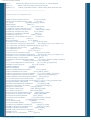
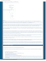
** Diagram of specified area on Control Board **
EDGE OF BOARD, viewed from the rear, looking toward front panel
Green jumper wires (B2, B3)
_______
___ ___ ___ ___ ___
-|
|- | _ | | _ | |_ _| |_ _| |___|
-| XRU |- B0| | B1| | B2 | B3 |
-| 4066BF|- |_| |_| _|_ _|_ ___
-|
|- |___| |___| |___| |___| |___|
-|
|_______
-|
|-|
|-|_______|-|
|-|
|-|
|-|
|-|
|-|_______|The jumpers are actually soldered on the other side of the board, but the loops come up over the top and hang over the B0/B1 side.
B0=R414
B1=R412
Here's something interesting! According the Kenwood rep I spoke to, performing this mod *does not* void your factory warranty. The same
goes for any Kenwood published service bulletin or modification info. We are encouraged to perform the repairs ourselves to save them the
trouble and expence.
19-07-1998
DTMF Remote via Microphone
The TM-733 is fully DTMF remotable via the microphone (documented). The radio can also be externally DTMF controllable with an HT, but
that will be described later.
The DTMF control keys are exactly as shown on page 81 of the manual. Note that the microphone is active all the time, so any ambient DTMF
tones near your mic will also change rig settings. This includes tones coming in on the other band and out the speaker.
Cross Band Repeating
Cross band repeat isn't documented but comes ready from the factory.
To enable cross band repeat from the front panel, first select a band by pressing BAND SELECT. Then, change the control to the other band
by hitting [CONT SEL]. Next, press [F] for one second, then the "X" button (far right side). Decimals will appear between the Kilohertz digits,
and the "ON" indicator will light momentarily. The microphone sequence to enable cross band repeat while in remote control mode is "DC".
The transmitter hang time can be toggled between 500ms to 0ms by turning on the radio with [LOW] pressed. They also recommend enabling
the Time-out Timer, for obvious reasons.
Note that the TM-733 can also be used as a "one-way" cross-band repeater.
For example, if you can receive a distant repeater with your HT, but have difficulty getting into it, you can use the TM-733 to boost your
transmitted signal. To set this up, just omit the part where you "change the control to the other band by pressing [CONT SEL]." Doing this will
setup the TM-733 to repeat your signal to the other band, but will not retransmit the distant station back to you. If this sounds ambiguous, play
around with it a little and it will begin to make sense.
http://www.kb2ljj.com/data/kenwood/TM-733.htm (6 di 9)30/08/2009 18.42.07
KB2LJJ Radio Mods Database and Manuals
DTMF Paging and Squelch
The DTMF Paging & DTMF Squelch protocol (AAA*BBB) is compatible with the Yaesu 530 and all Kenwood radios supporting this.
Wireless Cloning
The advertised but undocumented Wireless Clone function is described in App Note AAN-0008 which they will mail out on request. (Maybe if
enough people ask for it, they will include all the functions in future instruction manuals.) In summary:
●
●
●
●
●
●
●
Prepare the two radios for simplex operation on the same frequency.
Turn both radios off
Press [CALL]+[SHIFT] + [Pwr On].
This should place the radios is clone mode with "CLonE" on the display.
Press PTT on the "Master" radio momentarily. This will start sending the programming DTMF tones.
After all data has been transferred, the display of all radios will read "End", indicating success.
If the signal is interrupted or corrupted, the "Slave" displays will read "Err". Turn them off and try again.
Notes:
●
●
Both the Master and Slave radios must have the same number of memory channels available for each band. Example: You can not
clone a stock Master to a Slave with ME-1 memory expansion.
You can not clone between different Kenwood radio models, even if they seem identical.
Be careful when using the clone feature. It has been known to wipe out or scramble memories on the master radio during or right after clone.
TM-733A PL Tone Distortion
Symptom
Transmitted PL tones at the receiving station have a relatively high level of distortion. This is easily seen when the incoming signal is viewed
on an oscilloscope.
Countermeasure
Change the value of the "Pull-up" resistors in the PL tone encoder circuit as shown in the accompanying chart and illustration. This reduces the
distortion from around 9% to approximately 4%.
Part OLD value NEW value
---- --------- --------R542 1.8k
2.7k
R543 1.8k
3.3k
R544 1.8k
4.7k
R545 1.8k
6.8k
R546 1.8k
10k
R547 1.8k
10k
R548 1.8k
10k
Procedure
1.
2.
3.
4.
5.
6.
7.
8.
9.
Disconnect the power cable, microphone and antenna's, etc.
Detach the front panel and set it aside.
Remove the top and bottom covers.
Remove the speaker and speaker mounting bracket.
Disengage the plastic front panel from the main chassis.
Carefully disconnect the two ribbon cables from the Tx/Rx unit C/4.
Remove the two Phillips head screws that secure the Tx/Rx unit to the chassis.
Turn the circuit board over and replace the resistors using the parts list and illustration as a guide.
Reverse steps 1-7 for reassembly.
http://www.kb2ljj.com/data/kenwood/TM-733.htm (7 di 9)30/08/2009 18.42.07
KB2LJJ Radio Mods Database and Manuals
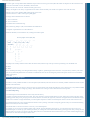
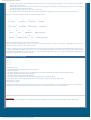
TX-RX Unit (X57-4360-00) Foil Side View
---------------------------------------------------------------
R
5
4
7
R R R542
5 5
4 4 R543
6 4
R545
(IC403 on component side) R
5
4
8
_______
-|
|-|
|-|
|-| IC402 |-|
|-|
|-|_______|Caution:
This modification requires advanced surface mount soldering equipment that is rated for CMOS circuits. It also requires familiarity with
advanced surface mount soldering techniques. If you do not have the proper equipment or knowledge do not attempt this modification yourself.
Seek qualified assistance from your closest Kenwood Service Center (Long Beach, CA, or Virginia Beach, VA).
The Service Manual specifies a test for the PL. The technician is simply required to verify that any one PL tone is between 500 and 1500 Hz
deviation. This is quite a wide tolerance range! The "standard" PL tone deviation should be 750 Hz. Twice that strong might be too strong and
become audible. There are no trim-pots on the PL deviation, so I'm guessing that the deviation is pretty constant from radio to radio.
The dirty PL is definitely found on early models, but we have had many reports that the PL problem has been fixed in newer versions of the
radio. If you purchased your radio after September 15, 1994, (or your serial number is greater than 55000000) it's a good chance that you may
not have the PL problem.
The other problem concerns the DTMF Confirmation Tones. This feature is off by default (I wonder why :), while it seems pretty useful. To
turn it on, press [PTT] + [Down] on the microphone while powering the radio on. This will generate short DTMF confirmation tones whenever
you send DTMF over the air from the keypad. Unfortunately, it mangles the beginning of the outgoing DTMF tone! This is serious enough that
most local repeaters can't detect the tone, or count it as two tones.
Get a receiver and listen to what you are sending out when the Confirmation tones are enabled. It sounds to me like they may be mixing the
confirmation tone in with the real tone and getting some destructive interference. Just a guess, though.
I called a Kenwood technician (Ricardo) and worked with him on the phone to reproduce the problem there. So, as of today, this is a Known
Problem, and they are looking into a fix. :-)
I am really curious to know what they would say if other folks called up and complained about this problem. Would they deny hearing about it,
or would it really be a Known Problem? Might give some insight into the PL-noise denial thing anyway. :-)
Personally, I'm much more concerned about the noisy PL than the DTMF confirmation tones, since I can just shut those off and pretend that
feature doesn't exist. If enough people call about the PL problem, maybe they will come out with a real fix and offer it under warranty to all the
radios out there (since they're all pretty new). My guess is that it will involve a free TSU-8 tone decode module, but don't hold your breath. :-)
External DTMF Remote Control
The following procedure places the 733 in External DTMF Remote Control.
Note that this mode is different than DTMF Remote Mode. This mode concerns the control of the 733 with an HT, and not the microphone.
●
●
●
●
●
●
●
Press Band Select and select the UHF band.
Pick a UHF control frequency.
Turn on the UHF DTSS function and select a tone sequence. (p. 89)
Turn the UHF DTSS function back off.
Press Band Select to move to the VHF band.
Press [CONT SEL] to move control back to the UHF band.
Turn OFF the radio, press and hold [CONT SEL] while turning the radio back on, then release [CONT SEL]. The S-meter scale and
the DT indicators for the UHF band will begin flashing. The LOCK indicator will turn ON, and most front-panel keys (except PWR)
will be disabled.
http://www.kb2ljj.com/data/kenwood/TM-733.htm (8 di 9)30/08/2009 18.42.07
KB2LJJ Radio Mods Database and Manuals
To begin remote control, you should key the external radio and press the following key sequence: "Axxx#" where "xxx" is the preset
DTSS code selected earlier.
If the proper code is received by the 733, the beeper will sound and the DT indicator will stop flashing. The radio can now be remotely
controlled using the function chart below.
To return to standby mode, press "A#" on the remote radio.
To return the radio to normal operation, turn the radio off, then press and hold [CONT SEL] while turning the radio back on.
●
●
●
●
Refer to this chart when using the TM-733 in "External DTMF Control".
1
2
T.ALT ON
3
TONE ON
A
CTCSS ON
ENTER
4
5
T.ALT OFF
6
TONE OFF
B
CTCSS OFF
TONE SEL
7
CALL
8
*
DOWN
0
9
VFO
C
MEMORY
#
D
POWER LEVEL
UP
REPEATER ON
REPEATER OFF
There are no "shifted" functions. Just one function per button.
After you hit "B" for TONE SELECT, press * or # to go up or down, and same is true when in VFO mode or in MEMORY mode. Tones 7, 8,
and 9 mimic the three buttons at the top of the 733 mic.
Pressing "C" places the radio in cross band repeat mode. You will recognize this because of the dots between Kilohertz digits. After pressing
"C", put the radio back into standby mode with "A#". The 733 will now cross band repeat. To disable cross band repeat, place the radio back
into the External DTMF Remote Control with "Axxx#". If you can read through the lines, the 733 is capable of operating as a frequency agile
remote base. Now Kenwood just needs a CW IDer!
TM-733 data pinouts descriptions
o o
o o
o o
On the booklet it says
1 = pkd packet data input transmit data frm tnc to tranciever.
2 = de ground for pkd.
3 = pks packet standbye tnc can use this pin to inhibit the the transciever microphone input while transmiting packet signals.
4 = pr9 detects 9600 bps data (500 mvp-p/10 kohms).
5 = pri detects 1200 bps data (300mvp-p/10kohms).
6 = sqc squelch control output inhibits tnc data transmit while transceiver squelch is open.
Prevents interference to voice communications on the same frequency. allso prevents retries. output level
open squelch: +5 v (high)
closed squelch: 0v (low)
I bought a baycom board,ive tried to put the baycom boad 5 pin din plug to this but faild so far on one attempt,if you are very good with the
practical side of radio's could you please tell me the proper way to wire my kenwood tm 733e up the the baycom.
ATTENTION
The KB2LJJ takes no responsibility for any damage during the modification or for any wrong information made on this modification.
http://www.kb2ljj.com/data/kenwood/TM-733.htm (9 di 9)30/08/2009 18.42.07