1
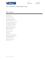
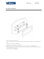
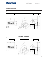
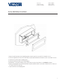
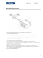
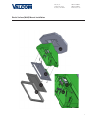
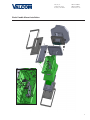
Installation and Programming Manual V1.03
V-D11025A / V-D11040A Digital Clocks
Valcom, Inc.
5614 Hollins Road
Roanoke, VA 24019
540-563-2000 P.
540-362-9800 F.
www.valcom.com
Valcom, Inc.
5614 Hollins Road
Roanoke, VA 24019
540-563-2000 P.
540-362-9800 F.
www.valcom.com
V-D11025A/V-D11040A Digital Clocks
Table of Contents
Table of Contents—2
Flush Mount Installation—3
Flush Mount Installation—4
Surface (Wall) Mount Installation—5
Metal Double Mount Installation—6
Plastic Surface (Wall) Mount Installation—7
Plastic Surface (Wall) Mount Installation—8
Plastic Double Mount Installation—9
Plastic Double Mount Installation—10
Plastic Double Mount Installation—11
Wiring and Jumper Settings—12
V-D11025A/V-D11040A Slave Mode—13
59 Minute Correction—14
58 Minute Correction—14
National Time/Rauland—15
Dukane—15
Rauland Digital—16
Midnight Reset or Once a Day Pulse—16
Setting the Time on the Digital Clock—17
Programming the Digital Clock—17
Relay Output Selections—23
Frequently Asked Questions—24
Troubleshooting—25
*manuals may change without prior notice
2
Valcom, Inc.
5614 Hollins Road
Roanoke, VA 24019
540-563-2000 P.
540-362-9800 F.
www.valcom.com
Flush Mount Installation
1. Mount the flush mount box into the wall.
2. Connect the ground wire into the flush mount box using the tooth lockwasher and the machine screw nut (included in the
kit).
3. Disconnect the red filter from the display panel.
4. Connect the wiring as shown on the wiring diagram.
5. IMPORTANT: If using a low voltage system (24 volt) make sure that the transformer is an isolated transformer.
6. Mount the display panel into the flush mount box using the four (4) black machine screws (#6, included in the kit). Make
sure the switches are on the right side.
7. Snap the red filter into the display panel.
3
Valcom, Inc.
5614 Hollins Road
Roanoke, VA 24019
540-563-2000 P.
540-362-9800 F.
www.valcom.com
Flush Mount Installation
Flush Mount Picture 2.5”
Figure 1
Front View:
Side View
Flush Mount Angled View:
D3 = .28”
D4 = 3.5”
H = 4.65”
H = 4.65”
W = 10.3”
Flush Mount Picture 4.0”
Figure 2
Front View:
Front view:
Side View
Flush Mount Angled View:
D3 = .28”
D4 = 3.5”
H = 7.5”
4
Valcom, Inc.
5614 Hollins Road
Roanoke, VA 24019
540-563-2000 P.
540-362-9800 F.
www.valcom.com
Surface (Wall) Mount Installation
1. Mount the wall mount box into the double gang box using four machine screws (#6-32) included in the kit.
2. Connect the ground wire into the flush mount box using the tooth lockwasher and machine screw nut (included in the kit).
3. Disconnect the red filter from the display panel.
4. Connect the wiring as shown on the wiring diagram.
5. IMPORTANT: If using a low voltage system (24 volt) make sure that the transformer is an isolated transformer.
6. Mount the display panel into the flush mount box using four (4) black machine screws (#6, included in the kit). Make sure
the switches are on the right side.
7. Snap the red filter into the display panel.
5
Valcom, Inc.
5614 Hollins Road
Roanoke, VA 24019
540-563-2000 P.
540-362-9800 F.
www.valcom.com
Metal Double Mount Installation
1. Screw hanger/mounting rod (included in the kit) into the crossbar (also included in the kit).
2. Insert wires through hanger/mounting rod.
3. Install crossbar using two (2) #6-32 screws into double gang box.
4. Mount the double mount box into the clock base using two (2) #6 nuts and Tooth Lockwasher #6. (The double mount can be
mounted either on the wall or on the ceiling).
5. Insert the two (2) locking hole plugs (0.187”) and the locking hole plug (0.562”) into the unused holes.
6. Insert double mount case onto the hanger/mounting rod.
7. Insert the support bracket onto the hanger/mounting rod.
8. Screw the two (2) nuts (included in the kit) onto hanger/mounting rod and secure the clock base to wall.
9. Connect the ground wire into the double mount box using the tooth lockwasher and machine screw nut (included in the kit).
10. Disconnect the red filter from the display panel.
11. Connect the wiring as shown on the wiring diagram.
12. IMPORTANT: If using a low voltage system (24 volt) make sure that the transformer is an isolated transformer.
13. Mount the display panel on one side of the double mount box using four (4) black machine screws (#6, included in the
kit). Make sure the switches are on the right side.
14. Snap the red filter into the display panel.
15. Repeat steps 9-13 for the second clock.
6
Valcom, Inc.
5614 Hollins Road
Roanoke, VA 24019
540-563-2000 P.
540-362-9800 F.
www.valcom.com
Plastic Surface (Wall) Mount Installation
q
r
w
t
e
y
7
Valcom, Inc.
5614 Hollins Road
Roanoke, VA 24019
540-563-2000 P.
540-362-9800 F.
www.valcom.com
Plastic Surface (Wall) Mount Installation
q Mount Housing to Wall and/or Gang Box - To mount the housing to the wall, drive two (2) plastic anchors into the wall (not
supplied in kit) and take two pan head screws (also not supplied in kit) and drive them into the plastic inserts leaving an 1/8th inch
gap between the head of the screw and the wall. Mount the housing to the wall by lining up the two holes in the back of the top of
the housing with the two screws with the 1/8 inch gap from the wall and slide the housing onto the heads of the screws. To mount the
housing to the gang box, take the four (4) 6-32 x 1” screws (supplied in kit) and screw them through the four holes in the center of the
inside of the housing and the four holes in the gang box.
Note: If using a metal gang box, a ground must be provided to the gang box.
w
Feed Wiring Into the Housing - Take the wire coming from the inside of the gang box and feed it through the hole in the middle of
the housing.
e
Plug and Secure Wiring - Loosen the provided wire clamp (comes attached to the inside of the housing) and slip excess wiring
through and tighten the clamp. After securing excess wiring, plug the jack at the end of the wiring into the appropriate jack on the back
of the display board.
r Mount Display Board to Housing -
Using the four (4) self tapping, 6-19 x 1/2” flat head screws supplied in the assembly kit, take
the display board and screw it to the front side of the clock housing (4 screws per clock).
t
y
Snap on Filter - Take the red filter bezel and snap it on to the front side of the housing.
Snap on Frame - Take the gray frame and snap it on to the front side of the housing.
8
Valcom, Inc.
5614 Hollins Road
Roanoke, VA 24019
540-563-2000 P.
540-362-9800 F.
www.valcom.com
Plastic Double Mount Installation
q
a
o
t
i
e
u
y
w w
r
9
Valcom, Inc.
5614 Hollins Road
Roanoke, VA 24019
540-563-2000 P.
540-362-9800 F.
www.valcom.com
Plastic Double Mount Installation
*For metal mounting bracket: Use a wall anchor that can support 50 lbs or more with a maximum
screw size of 10/1.5”
q Install metal mounting bracket - First, remove the metal mounting bracket from the inside of the double mount base by unscrewing
the two (2) 6-32 x 1/2” screws located on the underside of the base (save these screws for step #5). Next, screw the metal mounting
bracket to the wall or ceiling in which the clocks are being installed. To mount to the switch box, screw the four (4) 6-32 x 1” screws
supplied in the assembly kit through the inner four holes of the metal mounting bracket. Use the outer four holes to mount anchors
to the wall (both anchors and screws for anchors not supplied in kit). For IP clocks, if using an Ethernet bracket (*as shown in the
diagram) use the two (2) 6-32 x 1/4” included in the assembly kit to mount the Ethernet bracket to the metal mounting bracket at this
point(Ethernet bracket not supplied in assembly kit).
Note: if using a plastic switch box, a ground wire must be routed through the switch box and into one (1) of the four (4) metal mounting bracket screws in order to provide ground to the metal mounting bracket.
Note: the metal mounting bracket MUST be secured by both the screws going to the switch box AND the anchors going into the wall.
w Mount clock housings to pole - Align the hole in the center each housing with one of the three holes on the mounting pole where
the wiring will be routed (the installer will chose which hole at the end of the pole to use based on how far they want the clock to sit
from the wall). Screw from the inside of the housing into the four holes surrounding the hole in the center of the housing using the four
(4) 8-32 x 7/16” screws supplied in the assembly kit (4 screws per clock), securing both housings to the mounting pole.
Note: end caps from one side of each clock must be removed to mount both clocks to the mounting pole. Remove one end cap from each clock from the side in which the mounting pole enters the clock.
e Screw both housings together - Using the two (2) self tapping, 6-19 x 7/16” screws supplied in the assembly kit, screw both back
sides of the clock housings together (2 screws per clock).
r Feed wiring through base and pole - Take the wiring coming from the switch box and begin to feed it through the center of the
base of the mounting assembly until it emerges from the hole in the center of the clock housing. Make sure there is roughly 1.5’ - 2’
of wiring coming from the switch box. Perform this task for both clocks. If installing IP clocks, run bare Ethernet wire without an RJ45
connector and install the connector after it has been routed through the clock if possible (this will be much easier than running the wire
with the connector on). If not possible, make sure that there is no boot present in order for the connector to fit through the assembly.
If you are using an Ethernet bracket with the installation of IP clocks, the assembly of the clocks in steps 6 and 7 can be accomplished
before mounting the assembly to the wall in step 5 - making the overall installation more simple.
*instructions continued on next page
10
Valcom, Inc.
5614 Hollins Road
Roanoke, VA 24019
540-563-2000 P.
540-362-9800 F.
www.valcom.com
Plastic Double Mount Installation
t
S nap and screw base to metal mounting bracket - Snap the base to the metal mounting bracket by first making contact
with the lip in the upper side of the base and the metal mounting bracket. When the base has been snapped onto the bracket, take
the two (2) 6-32 x 1/2” pan head screws that orginally came installed on the base and screw them back into the two holes on the
underside of the base to secure the base to the metal mounting bracket.
y
Connect switch box wires to clock harness - Take the wiring harness supplied with the clock and make all necessary
connections between the wiring harness and the switch box wires using wire nuts. Perform this task for both clocks. If using IP
clocks, wiring will not be supplied with the clocks - the installer will be responsible for supplying all Ethernet wiring.
u
Plug and secure wiring - Loosen and slip excess wiring through provided wire clamp (comes attached to each housing) and
tighten the clamp. After securing excess wiring, plug the jack at the end of the wiring harness into the appropriate jack on the back
of the display board. Perform this task for both clocks.
i Mount display board to housing -
Using the four (4) self tapping, 6-19 x 1/2" flat head screws supplied in the assembly kit,
take the display board and screw it to the front side of the clock housing (4 screws per clock).
o
a
Snap on filter - Take the red filter bezel and snap it on to the front side of each clock housing.
Snap on frame - Take the gray frame and snap it on to the front side of each clock housing.
11
Valcom, Inc.
5614 Hollins Road
Roanoke, VA 24019
540-563-2000 P.
540-362-9800 F.
www.valcom.com
Wiring Information
Wiring and Jumper Settings
/ 220 VAC POWER
/ 220 VAC POWER
12
Valcom, Inc.
5614 Hollins Road
Roanoke, VA 24019
540-563-2000 P.
540-362-9800 F.
www.valcom.com
Wiring Information
V-D11025A/V-D11040A Slave Mode
V-CCU
+
-
+ -
+
-
13
Valcom, Inc.
5614 Hollins Road
Roanoke, VA 24019
540-563-2000 P.
540-362-9800 F.
www.valcom.com
Interfacing with Other Systems
59 Minute Correction
Description:
110 VAC/24 VAC 60 Hz is used to run the clock normally. Applying an eight (8) second reset signal from 57 minutes and 54 seconds will cause an
hourly correction. Applying a fourteen (14) second reset signal from 5:57:54 will cause a daily correction.
Instructions:
1. In programming mode, set option 31 to 05.
2. Connect interface harness as shown in the diagram.
Note: Manually set the slave clock to the time from the master clock upon initial connection. After the slave clock receives its first daily correction,
the clocks will be perfectly synchronized.
58 Minute Correction
Description:
110 VAC/24 VAC 60 Hz is used to run the clock normally. See digital clock Programming Manual for the four variations of 58 Minute Correction.
Instructions:
1. In programming mode, set option 31 to 01, 02, 03, 04.
2. Connect interface harness as shown in the diagram.
Note: Manually set the slave clock to the time from the master clock upon initial connection. After the slave clock receives its first daily correction,
the clocks will be perfectly synchronized.
14
Valcom, Inc.
5614 Hollins Road
Roanoke, VA 24019
540-563-2000 P.
540-362-9800 F.
www.valcom.com
Interfacing with Other Systems
National Time/Rauland
Description:
110 VAC/24 VAC 60 Hz is used to run the clock normally. Applying a 25 second reset signal when minutes equal 00 and seconds equal 00 will
cause an hourly correction. Applying a 24 minute reset signal when hours equal 06 or 18 and minutes equal 00 and second equals 25 will cause a
daily correction.
Instructions:
1. In programming mode, set option 31 to 06.
2. Connect interface harness as shown in the diagram.
Note: Manually set the slave clock to the time from the master clock upon initial connection. After the slave clock receives its first daily correction,
the clocks will be perfectly synchronized.
Dukane
Description:
Applying a 4-10 millisecond pulse on the minute line will increment the clock in one minute.
Applying a 12-50 milisecond pulse on the reset line will bring the clock back to 12:00 a.m.
Instructions:
1. In programming mode, set option 31 to 07.
2. Connect interface harness as shown in the diagram.
15
Valcom, Inc.
5614 Hollins Road
Roanoke, VA 24019
540-563-2000 P.
540-362-9800 F.
www.valcom.com
Interfacing with Other Systems
Rauland Digital
Description:
Applying a half second pulse for every minute to the Dig. Line will bring the clock to the correct time. The clock will jump to the correct time at the
end of the correction pulse.
Note: For better synchronization, it is recommended to work on a 60 Hz time base.
Note: Use only an isolated transformer to run the clock in 24 volt mode.
Instructions:
1. In programming mode, set option 31 to 08
2. Connect the interface harness as shown in the diagram.
Midnight Reset or Once a Day Pulse
Description:
Applying a minimum of two (2) second pulse will bring the clock to the correct time.
Note: Please refer to the following page for directions on how to set the time of the pulse.
Instructions:
1. Set Option 31 to 09.
2. Connect the harness.
16
Valcom, Inc.
5614 Hollins Road
Roanoke, VA 24019
540-563-2000 P.
540-362-9800 F.
www.valcom.com
Programming
Setting the Time on the Digital Clock
1. To set the time, press the top button to change the hour and/or the bottom button the set the minute.
Set Hour
Set Minute
Programming the Digital Clock
Use the following options to program a once-a-day pulse output. Enter the programming mode by pushing the “Set Hour” and “Set Minute”
buttons at the same time. The AM/PM indicator in the upper left corner will start blinking indicating that you are in programming mode.
Note: in order to program these following options, option 30 must first be set to “E” and option 31 must be set to “09”.
Option 1 - Set Year:
Use the bottom button to scroll from “00-99” on the display and set
the year.
Option 2 - Set Month:
Use the bottom button to scroll between “01-12”.
Option 3 - Set Day:
Use the bottom button to scroll between “01-31”.
17
Valcom, Inc.
5614 Hollins Road
Roanoke, VA 24019
540-563-2000 P.
540-362-9800 F.
www.valcom.com
Option 4 - Set 12/24 Hour Mode:
Use the bottom button to scroll between “12 or 24”.
Option 5 - Daylight Savings Time:
Press the bottom button to scroll between “d”, “1”, or “2”.
“d” will disable this option.
“1” will enable daylight savings pre 2007.
“2” will enable daylight savings post 2007.
Option 6 - Alternating Time/Date Display:
Press the bottom button to scroll between “E” or “d”.
When enabled (E), the display will switch between showing the time
(HH:MM:SS) and the date (MM:DD:YY). When disabled (d), the display
will show the time only. Pressing the “Set Minute” button allows the
user to select between “E” and “d”.
Option 7 - American or European Date Style:
Press the bottom button to scroll between “A” or “E”.
American style shows the month, day and year (ex. 10 28 08). European style shows day, month and the year (ex. 28 10 08). The date will
be displayed during normal operation only if the “Alternate Time/Date”
option has been enabled in option 6.
Option 8 - Brightness:
Press the bottom button to scroll between “0” and “1”.
Level 0 is the normal brightness and 1 is the brightest setting.
18
Valcom, Inc.
5614 Hollins Road
Roanoke, VA 24019
540-563-2000 P.
540-362-9800 F.
www.valcom.com
Option 9 - Set the Clock Number:
Use the bottom button to scroll between “001-999”.
This two-step function allows the user to program the address (clock
number and zone number) for the display for numeric messaging.
Option 10 - Set the Zone Number:
Press the bottom button to scroll between “00-99”.
This allows for the second step, programming of the two-digit zone
number for numeric messaging.
Option 11 - RS485 Data Rate:
Press the bottom button to scroll between “00-12”.
01 - Data is transmitted every second
02 - Data is transmitted every 5 seconds
03 - Data is transmitted every 10 seconds
04 - Data is transmitted every 15 seconds
05 - Data is transmitted every 30 seconds
06 - Data is transmitted every minute
07 - Data is transmitted every 2 minutes
08 - Data is transmitted every 5 minutes
09 - Data is transmitted every 10 minutes
10 - Data is transmitted every 15 minutes
11 - Data is transmitted every 30 minutes
12 - Data is transmitted every hour
Option 12 - Set the Time Base:
Press the bottom button to scroll between “q” and “E”.
This option allows the user to select either an Electric Time Base (E) of
60 Hz or a Quartz Time Base (q). If a 60 Hz signal is not available, the
clock will automatically revert to a quartz time base.
Option 13 - Loss of Communication Alert:
Press the bottom button to scroll between “E” and “d”.
Enabling (E) this option will allow the user to proceed to option 14 to
set the loss of communication alert. Disabling (d) this option will not
show a loss of communication and will keep the colons solid. Disabling
should also be used when the clock is in an independent mode.
19
Valcom, Inc.
5614 Hollins Road
Roanoke, VA 24019
540-563-2000 P.
540-362-9800 F.
www.valcom.com
Option 14 - Set the Loss of Communication Alert:
Use the bottom button to scroll between “01-10”.
This option allows the user to set when the colons will flash after the
clock loses data to indicate loss of communication. Press the “Set Minute” button to scroll between “01-10”.
01 - Data is lost after 5 minutes
02 - Data is lost after 10 minutes
03 - Data is lost after 15 minutes
04 - Data is lost after 30 minutes
05 - Data is lost after 45 minutes
06 - Data is lost after 60 minutes
07 - Data is lost after 90 minutes
08 - Data is lost after 120 minutes
09 - Data is lost after 180 minutes
10 - Data is lost after 240 minutes
Option 20 - Set the Programmable Relay:
Press the bottom button to scroll between “d” to “1-9”.
Please see page 28 to choose the desired setting. If option “9” is
selected, than the user will proceed to option 24. If not, then the user
will proceed to option 30.
Option 21 - Once a Day Pulse Output- Hours:
Press the bottom button to scroll between “00-23”.
This option allows the user to set the hour they want the relay to close.
Option 22 - Once a Day Pulse Output - Minutes:
Press the bottom button to scroll between “00-59”.
This option allows the user to set the minute(s) they want the relay to
close.
Option 23 - Once a Day Pulse Output - Seconds:
Press the bottom button to scroll between “00-59”.
This option allows the user to set the second(s) they want the relay to
close.
20
Valcom, Inc.
5614 Hollins Road
Roanoke, VA 24019
540-563-2000 P.
540-362-9800 F.
www.valcom.com
Option 24 - Once a Day Pulse Output - Set Duration:
Use the bottom button to scroll between “01-99”.
This option allows the user to set the duration of the relay closure (in
seconds)
Option 30 - Auxiliary Input Control:
Use the bottom button to scroll between “E” and “d”.
If the option is set to “d” (disable), the following option will be 40. Setting the option to “E” (enable) will enter an input control mode.
Option 31 - Settings the Auxiliary Input Control:
Press the bottom button to scroll between “1-9”.
01 - 58 Minute Correction (1)
02 - 58 Minute Correction (2)
03 - 58 Minute Correction (3)
04 - 58 Minute Correction (4)
05 - 59 Minute Correction
06 - National Time/Rauland
07 - Dukane Digital
08 - Rauland Digital
09 - Once A Day Pulse
Option 32 - Once a Day Pulse Input- Hours:
Press the bottom button to scroll between “00-23”.
This option allows the user to set the hours they want the clock to go
to.
Option 33 - Once a Day Pulse Input - Minutes:
Press the bottom button to scroll between “00-59”.
This option allows the user to set the minutes(s) they want the clock to
go to.
21
Valcom, Inc.
5614 Hollins Road
Roanoke, VA 24019
540-563-2000 P.
540-362-9800 F.
www.valcom.com
Option 34 - Once a Day Pulse Input - Set Duration:
Use the bottom button to scroll between “01-59”.
This option allows the user to set the second(s) they want the clock to go
to.
Option 40 - Activating Diagnostic Mode:
Use the bottom button to scroll between “E” and “d”.
If the option is set to “d” (disable), pressing the top button will take the
user back to the time. Setting the option to “E” (enable) will enter option
41.
Option 41 - Setting the Diagnostic
Press the bottom button to scroll between “1-5 and 9”.
01 = Diagnostic 1
02 = Diagnostic 2
03 = Diagnostic 3
04 = Diagnostic 4
05 = Diagnostic 5
09 = Overrides diagnostic to go to the master clock time
Option 42 - Duration of time Until the Clock Resumes Normal Operation:
Press the bottom button to scroll between “00-99”.
This option shows how much time the information on the clock from diagnostics 1 or 2 will be displayed before going back to normal operation.
Refer to the specific analog clock’s installation manual for diagnostic
information.
22
Valcom, Inc.
5614 Hollins Road
Roanoke, VA 24019
540-563-2000 P.
540-362-9800 F.
www.valcom.com
Relay Output Selections
“d” = Disables the relay output selection mode.
“1” = 58th minute (1) - The hourly correction for 55 seconds every hour from XX:58:05 to XX:59:00. The daily correction (5 a.m. & 5 p.m.) is
ten correction cycles sent to the relay (each for 95 seconds) beginning at 5:05:00, 5:07:00, 5:09:00, 5:11:00, 5:13:00, 5:15:00, 5:17:00, 5:19:00,
5:21:00, and 5:23:00.
“2” = 58th minute (2) - The hourly correction for 60 seconds every hour from XX:58:00 to XX:59:00. The daily correction (5 a.m. & 5 p.m.) is
twelve correction cycles sent to t he relay (each for 65 seconds on and 25 seconds off) beginning at 5:05:00 to 5:22:35.
“3” = 58th minute (3) - The hourly correction for 60 seconds every hour from XX:58:00 to XX:59:00. The daily correction (5 a.m. & 5 p.m.) is
twelve correction cycles sent to the relay (each for one minute on and two minutes off) beginning at 5:06:00.
“4” = 58th minute (4) - The hourly correction for 55 seconds every hour from xx:58:05 to XX:59:00. The daily correction (5 a.m. & 5 p.m.) is 12
correction cycles for 55 seconds. The timings will be 05:03:05, 05:07:05, 05:11:05, 05:15:05, 05:19:05, 05:23:05, 05:27:05, 05:31:05, 05:35:05,
05:39:05, 05:43:05 and 05:47:05.
“5” = 59th minute - The hourly correction for 8 seconds every hour from XX:57:54 to XX:58:02. The daily correction (5 a.m. & 5 p.m.) is a 14
second pulse from 5:57:54 to 5:58:08.
“6” = National Time & Rauland – The hourly correction is for 25 seconds every hour from XX:00:00 to XX:00:25. This option only has hourly
corrections.
7 - National Time & Rauland – The hourly correction is for 25 seconds every hour from XX:00:00 to XX:00:25. The daily correction (6 a.m. & 6
p.m.) is 25 seconds on, 35 seconds off every minute for 24 minutes.
8– N/A
9 - Once a Day Pulse - If selected, the next option will be 21 where the user can set the hours, minutes and seconds the user wants the clock to go
to when the relay is closed..
23
Valcom, Inc.
5614 Hollins Road
Roanoke, VA 24019
540-563-2000 P.
540-362-9800 F.
www.valcom.com
Support
Frequently Asked Questions
Can the V-D11025A or V-D11040A digital clock be used as an independent clock?
Yes, the clock is capable of being used as an independent, slave, master or chronograph clock.
Some clocks require a 9 volt battery backup for timekeeping. What happens to the V-D11025A or V-D11040A if a power failure occurs?
The V-D11025A or V-D11040A come equipped with a 10 year battery backup. Upon restoration of power, the clock immediately corrects itself from
its built-in time base. This occurs within seconds of “power-up”. Some clocks which do require a 9 volt battery backup risk having the battery
die during extended shut downs. Each individual clock must then be opened in order to replace the battery. Since the V-D11025A or V-D11040A
includes a 10 year battery backup, the clock never needs to be opened.
What happens to the V-D11025A or V-D11040A system if its input is lost?
Since the V-D11025A or V-D11040A digital clock is able to act as a master clock, if the communication input is lost to the V-D11025A or V-D11040A,
the clock will continue to run on its own. The V-D11025A or V-D11040A will also continue sending communication to any clocks down the line that
it is connected to.
How do I take advantage of the V-D11025A or V-D11040A chronograph functions?
The Valcom Control Box controls all chronograph functions of the V-D11025A or V-D11040A. The display can be programmed to show either
HH:MM or MM:SS, and the readout can count up from 00:00:00 to 99:59:59 or count down with a programmable starting point from 99:59:59 to
00:00:00, with interrupt and resume capabilities.
How many clocks can be run on the same communication line? What is the maximum distance between clocks on the communication
line?
Each V-D11025A or V-D11040A digital clock has a RS485 input and an output port. Each output port can drive up to 32 clocks in parallel, however
daisy chaining is the recommended wiring configuration. When using a daisy chain method of communication you can run an unlimited number of
clocks on the same communication line by connecting the clocks to each other individually where each clock drives the next clock in line. When
using a daisy chain wiring configuration, the maximum distance between each clock can be up to 3,000 feet. When an output drives more than
one clock in parallel, the combined length of all the lines emanating from one clock can not exceed 3,000 feet.
How can I display “BELL” text on the clock?
“BELL” displays can be programmed by V-WMCA master clocks.
24
Valcom, Inc.
5614 Hollins Road
Roanoke, VA 24019
540-563-2000 P.
540-362-9800 F.
www.valcom.com
Support
Troubleshooting
The clock is not running. What do I do?
a) Measure the input voltage to the clock. The voltage should measure 85-135 volts in the 110 volt model or 10-28 volts in the 2.5”/24 volt
model and 16-28 volt in the 4.0”/24 volt model.
b) Make sure the transformer is an isolated transformer if using a 24 volt model.
c) Make sure the ground wire is not touching other wires.
NOTE: If you fail to follow instructions b and c listed above, the fuses can be blown.
Clock is only displaying dashes. What do I do?
This means that the clock is receiving power but not receiving a time correction signal.
a)
Confirm that the head end is sending data to the clock power supply
b)
Confirm that clock power supply is wired correctly
The clock is displaying a time, but the colons are flashing. What does this mean?
This means that the clock, at one point has received a time update, but since then the correction has been lost.
a) Confirm that the head end is sending data to the clock power supply
b) Check to see that all wiring is correctly.
25