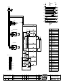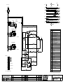
1
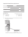
Simply Engineered Better
Technical Manual
For machines beginning with Serial No. W8100
Hood-Type
Dishwasher
Model
MH65-M2
High Temperature
with Built-in Booster
Machine Serial No.
September, 2003
Manual P/N
P. O. Box 4149
Winston-Salem, North Carolina 27115-4149
336/661-1556
Fax: 336/661-1660
113647
2674 N. Service Road
Jordan Station, Ontario, Canada L0R 1S0
905/562-4195
Fax: 905/562-4618
Moyer Diebel Ltd.
Complete the information below for quick reference.
Model Number
Serial Number
Voltage and Phase
Moyer Diebel Parts Supplier
Phone
Moyer Diebel Service Agency
Phone
Moyer Diebel Service:
Moyer Diebel (USA)
Phone: 1 (336) 661-1556
1 (800) 858-4477
Fax:
1 (336) 661-1660
Moyer Diebel Limited (Canada)
Phone: 1 (905) 562-4195
1 (800) 263-5798
Fax: 1 (905) 562-4618
Note: When calling to order parts, be sure to have the model number, serial number,
voltage and phase of your machine.
Machine Data Plate with
model & serial number
located on the right side
panel at the top.
COPYRIGHT © 2003 by Moyer Diebel (USA). All Rights Reserved.
REVISION RECORD
REVISION RECORD
Revision
Date
7/3/03
Revised
Pages
Serial Number
Effectivity
All
W8100
Comments
First issue of manual and
replacement parts lists
i
REVISION RECORD
Revision Record (CONT.)
ii
LIMITED WARRANTY
Limited Warranty
Moyer Diebel, P.O. Box 4183, Winston-Salem, North Carolina 27115, and P. O. Box 301, 2674 North Service
Road, Jordan Station, Ontario, Canada L0R 1S0 warrants machines, and parts, as set out below.
Warranty of Machines: Moyer Diebel warrants all new machines of its manufacture bearing the name
“Moyer Diebel” and installed within the United States and Canada to be free from defects in material and workmanship for a period of one (1) year after the date of installation or fifteen (15) months after the date of shipment by
Moyer Diebel, whichever occurs first. [See below for special provisions relating to Model Series DF and SW.] The
warranty registration card must be returned to Moyer Diebel within ten (10) days after installation. If warranty card
is not returned to Moyer Diebel within such period, the warranty will expire after one year from the date of shipment.
Moyer Diebel will not assume any responsibility for extra costs for installation in any area where there are
jurisdictional problems with local trades or unions.
If a defect in workmanship or material is found to exist within the warranty period, Moyer Diebel, at its election, will either repair or replace the defective machine or accept return of the machine for full credit; provided,
however, as to Model Series DF and SW, Moyer Diebel’s obligation with respect to labor associated with any repairs shall end (a) 120 days after shipment, or (b) 90 days after installation, whichever occurs first. In the event that
Moyer Diebel elects to repair, the labor and work to be performed in connection with the warranty shall be done
during regular working hours by a Moyer Diebel authorized service technician. Defective parts become the property
of Moyer Diebel. Use of replacement parts not authorized by Moyer Diebel will relieve Moyer Diebel of all further
liability in connection with its warranty. In no event will Moyer Diebel’s warranty obligation exceed Moyer
Diebel’s charge for the machine. The following are not covered by Moyer Diebel’s warranty:
a.
b.
c.
d.
e.
f.
g.
h.
i.
j.
Lighting of gas pilots or burners.
Cleaning of gas lines.
Replacement of fuses or resetting of overload breakers.
Adjustment of thermostats.
Adjustment of clutches.
Opening or closing of utility supply valves or switching of electrical supply current.
Adjustments to chemical dispensing equipment.
Cleaning of valves, strainers, screens, nozzles, or spray pipes.
Performance of regular maintenance and cleaning as outlined in operator’s guide.
Damages resulting from water conditions, accidents, alterations, improper use, abuse,
tampering, improper installation, or failure to follow maintenance and operation procedures.
Examples of the defects not covered by warranty include, but are not limited to: (1) Damage to the exterior or
interior finish as a result of the above, (2) Use with utility service other than that designated on the rating
plate, (3) Improper connection to utility service, (4) Inadequate or excessive water pressure, (5) Corrosion
from chemicals dispensed in excess of recommended concentrations, (6) Failure of electrical components due
to connection of chemical dispensing equipment installed by others, (7) Leaks or damage resulting from such
leaks caused by the installer, including those at machine table connections or by connection of chemical dispensing equipment installed by others, (8) Failure to comply with local building codes, (9) Damage caused by
labor dispute.
Warranty of Parts: Moyer Diebel warrants all new machine parts produced or authorized by Moyer Diebel to be
free from defects in material and workmanship for a period of 90 days from date of invoice. If any defect in material and workmanship is found to exist within the warranty period Moyer Diebel will replace the defective part without charge.
DISCLAIMER OF WARRANTIES AND LIMITATIONS OF LIABILITY. MOYER DIEBEL’S WARANTY
IS ONLY TO THE EXTENT REFLECTED ABOVE. CHAMPION MAKES NO OTHER WARRANTIES,
EXPRESS OR IMPLIED, INCLUDING, BUT NOT LIMITED, TO ANY WARRANTY OF
MERCHANTABILITY, OR FITNESS OF PURPOSE. MOYER DIEBEL SHALL NOT BE LIABLE FOR
INCIDENTAL OR CONSEQUENTIAL DAMAGES. THE REMEDIES SET OUT ABOVE ARE
THE EXCLUSIVE REMEDIES FOR ANY DEFECTS FOUND TO EXIST IN MOYER DIEBEL
DISHWASHING MACHINES AND MOYER DIEBEL PARTS, AND ALL OTHER REMEDIES ARE EXCLUDED, INCLUDING ANY LIABILITY FOR INCIDENTALS OR CONSEQUENTIAL DAMAGES.
Moyer Diebel does not authorize any other person, including persons who deal in Moyer Diebel Dishwashing
Machines to change this warranty or create any other obligation in connection with Moyer Diebel Dishwashing
Machines.
iii
FIV
FOREWORD
1. Read the instructions in this manual carefully. It contains important information on
installation, operation, and safety.
2. Store this manual carefully for future reference.
3. After removing packing material, check for loose parts in dishracks.
4. Before switching the equipment on, make sure that the model data plate conforms
to the electrical and water requirements supplied to this particular machine.
5. Installation should be carried out by qualified personnel according to the manufacturers instructions. The installation of your machine must meet all applicable
health and safety codes.
6. This equipment should be used for its intended purpose. Any other application
should be considered improper and therefore dangerous.
7. Only trained personnel should operate this equipment.
8. Operators must strictly follow all hygienic requirements in the handling of clean
dishware or cutlery.
9. Do not leave the machine in an environment at temperatures
lower than 0°C/32°F.
10. This machine should not be washed with a direct water stream.
11. Only qualified personnel should access the control panel after disconnecting
main power supply. Tag the disconnect indicating work is being performed
on that circuit.
12. Noise level of the machine is less than 67dB.
The manufacturer declines any responsibility for any printing errors contained in this
booklet.
The manufacturer also reserves the right to make any modifications to its products
that do not affect the basic characteristics thereof.
iv
TABLE OF CONTENTS
TABLE OF CONTENTS
Revision Record ...........................................................................................................
Limited Warranty .........................................................................................................
Foreward ......................................................................................................................
PAGE
i
iii
iv
1
GENERAL .................................................................................... 2
PART 1: OPERATION ................................................................... 3
PART 2: INSTALLATION AND MAINTENANCE ............................ 8
PART 3: REPLACEMENT PARTS .................................................. 11
PART 4: ELECTRICAL SCHEMATICS ........................................... 39
INTRODUCTION ..........................................................................
LIST OF FIGURES
Figure
Figure
Figure
Figure
Figure
Figure
Figure
Figure
Figure
Figure
Figure
Figure
Figure
Figure
Figure
1.1
1.2
3.1
3.2
3.3
3.4
3.5
3.6
3.7
3.8
3.9
3.10
3.11
3.12
3.13
–
–
–
–
–
–
–
–
–
–
–
–
–
–
–
Operations Detail ...................................................................................
Control Panel Detail ...............................................................................
Hood and Tank ........................................................................................
Door Handle and Springs ........................................................................
Door Switch and Block ...........................................................................
Tracks and Screens ..................................................................................
Wash and Rinse Spray Arms ..................................................................
Water Tank Components .........................................................................
Drain Assembly ......................................................................................
Wash and Rinse Piping ...........................................................................
Wash Pump Assembly ............................................................................
Booster Assembly ...................................................................................
Water Inlet Piping ...................................................................................
Control Panel ..........................................................................................
Control Cabinet .......................................................................................
3
7
12
14
16
18
20
22
24
26
28
30
32
34
36
v
Part 1:
INSTALLATION AND MAINTENANCE
This Page
Intentionally
Left
Blank
vi
INTRODUCTION
INTRODUCTION
Welcome to Moyer Diebel... and thank you for allowing us to take care of your dishwashing
needs.
This manual covers the hood-type dishwasher model MH-65.
Your machine was completely assembled , inspected and thoroughly tested at our factory before it
was shipped to your installation site.
This manual contains:
•
Installation and Instructions
•
Operation and Cleaning Instructions
•
Troubleshooting Guide
•
Basic Service Information
•
Replacement Parts Lists
•
Electrical Schematics
All information, illustrations and specifications contained in this manual are based upon the latest
product information available at the time of publication. Moyer Diebel constantly improves its
products and reserves the right to make changes at any time or to change specification without
notice and without incurring any obligations.
For your protection, factory authorized parts should always be used for repairs.
Replacement parts may be ordered from your Moyer Diebel authorized parts distributor or
authorized service agency. When ordering parts, please supply the model number, serial number,
voltage and phase of your machine, the part number, part description and quantity.
1
GENERAL
MODEL NUMBERS
MH-65
The MH-65 model is a high temperature (180°F/82°C rinse) sanitizing model with booster.
Standard Equipment Includes:
• Quick 65 second cycle
• 1.5 HP wash pump on anti-vibration pads
• Four large rectangular screens to maximize food
soil collection and improve resistance to clogging
• Field convertible from straight through
to corner operation
• Variable selector switch for 65, 120 and 180
seconds cycles
• Extended wash/de-lime cycles
(for heavily soiled items)
• Single electrical and water connections for
machine and booster
• Door safety switch
• Automatic tank fill/low-tank water heat protection
• Pressure Reducing Valve provided
•Detergent probe and rinse-aid connection points
provided
• Interchangeable upper and lower wash
and rinse arms
Options
•
Electric booster (70°F/39°C temperature rise) heater for 110°F/43°C supply water
Accessories
Additional dishracks:
Dish rack (peg)
P/N 101285
Silverware rack (flat bottom)
P/N 101273
Electrical Power Requirements: Fig
Elec Heat/Electric Booster
Model
Voltage
MH-65
Booster Rise
Rated
Amps
Minimum Supply Ckt.
Conductor Ampacity
208/60/1
40
45 Amps
60 Amps
60 Amps
MH-65
240/60/1
40
51 Amps
70 Amps
70 Amps
MH-65
208/60/3
40
26 Amps
35 Amps
35 Amps
MH-65
240/60/3
40
29 Amps
40 Amps
40 Amps
MH-65
208/60/3
70
37 Amps
50 Amps
50 Amps
MH-65
240/60/3
70
42 Amps
60 Amps
60 Amps
2
Maximum Overcurrent
Protective Device
PART 1:
OPERATION
PART 1: OPERATION
OPERATION AND USE
1. Before washing make sure that:
• the wall-mounted on/off switch is switched on;
• the water tap is open and water pressure is present,
• the pump suction filters are installed in their proper locations;
• the overflow tube is inserted in the drain;
• rotating spray arms move freely;
Auto/Manual Switch
• the rinse and detergent containers are full;
Manual Cycle Start(UP)
Extended Wash
(E)
Manual Start Switch
(M)
Heater OFF Light
(Only on S/N W8100-W8135)
(B)
(L)
Auto Manual Switch
2. Set switch “A” to position 1 to enable the
Door Activated Cycle (DOWN)
automatic filling of the wash tank. Once
the wash tank has filled and the tank heater
Machine Ready
(C)
turns on to make the tank reach temperature, the
heater then turns off and lamp “B” turns on
OFF Position
(this applies only to machines in the serial
number range W8100 to W8135).
In Cycle Light
(D)
Cycle Selection
Short - 65 Seconds
Medium-120 Seconds
Long -180 Seconds
Selector Switch
(A)
Figure 1.1 Operation Detail
3. Scrap and preflush all items to be washed
and load the items into the rack. Do not overload the rack. Wash only one layer of silverware in a rack.
4. Open the door and insert the rack into the machine.
5. By means of switch “A” select the wash cycle according to conditions of the dishware:
• with glasses or cups select the short cycle (pos.1)
• with normally dirty dishes or cutlery select the medium cycle (pos.2)
• with particularly dirty dishes or deep dishes select the long cycle (pos.3), or flip the
extended wash switch (E) down (only after starting a cycle). This will make the
dishmachine cycle in wash continuously until (E) is flipped up again; the machine will
then resume its normal cycle.
6. By means of selector “L”, select the wash cycle for automatic start when the hood is
closed, or for manual start by pressing the button “M”. Lamp “D” will switch off at the
end of the cycle.
NOTE:
This machine will continue to wash until the booster tank reaches temperature and the
thermostat shuts off; only then will the machine proceed to the rinse cycle.
3
Part 1:
OPERATION
PART 1: OPERATION (CONT.)
OPERATION AND USE (CONT.)
7. Remove the rack at a slight incline to permit all the water to drain; allow dishware to dry.
After washing one’s hands, handle the rack in such a manner as not to touch the
dishware inside, then place the rack on hygienically clean shelves.
8. At the end of washing, turn switch “A” to position “0”, empty out the tank by removing
the overflow tube. Then close the door and turn switch “A” to position “1” for a few
minutes to rinse out the inside of the machine. Finally, turn the switch “A” to position “0”
and wait until the tank is completely empty.
The scrap screens can now be taken out, washed, and then replaced.
Be certain that the overflow tube has been reinstalled.
9. When finished washing, switch off the machine by turning off the main disconnect switch
and turn off the water supply.
INSTRUCTIONS DURING THE WASH CYCLE
1. Do not put your hands into the water containing detergent. If this happens, wash them
immediately and thoroughly with fresh water.
2. Use only commercial non-foaming detergents.
3. When the machine is operating, do not open the door too quickly.
4. In the event the machine does not work properly, turn off the main power disconnect
switch and contact a technical service center authorized by the manufacturer for repairs.
5. Never modify the thermostat settings.
6. Wash tank water should be changed every two hours or after each meal period.
7. Do not subject clean dishware to any further cleansing treatment such as brushes or drying
towels.
!
4
CAUTION:
If these instructions are not followed, your safety and the equipment can be compromised.
PART 1:
OPERATION
MAINTENANCE:
IMPORTANT:
Before carrying out the cleaning and maintenance operations, turn off the main disconnect switch for the equipment.
Frequently check and clean the nozzles. Blocked nozzles will prevent the machine from
cleaning properly.
Do not use corrosive products such as sodium hypochlorite (bleach), acids, steel wool or
steel brushes to clean the inside and outside of the machine.
The presence of calcium and magnesium salt in the water can compromise machine
performance. Ask a qualified chemical person to remove the deposits periodically.
Stainless steel surfaces should be well cleaned in order to avoid some oxidation risks, or
chemical reactions.
OPTIMAL RESULTS:
Poor wash results can be noted when residue remains on the dishware.
Poor results can be caused by an insufficient rinse: in this case check that the rinse nozzles
are clean and that there is sufficient water supply pressure (20-22 PSI/138-151 kPa) during
machine rinse cycle..
In case of dishware residue check that:
• the washing nozzles are clean
• the wash water temperature is a minimum of 60°C/140°F
• there is detergent in the container
• the pump suction filter is clean
• the racks are suitable for the dishes and cutlery that are to be washed
• the position of the cutlery and the dishes in the racks are correct
• the racks are not overloaded with wares
TEMPORARY MACHINE NONUSE:
In case the machine is not used for a prolonged period, it is recommended to fill the
wash tank and run the machine with clean water, then drain, in order to avoid the
forming of bad odors.
If necessary repeat this step until all water leaving the machine is clean.
If the machine is not used for long periods, it is recommended to oil the stainless steel
surfaces with paraffin oil and to empty the water from the booster tank and the wash
pump.
5
Part 1:
OPERATION
PART 1: OPERATION (CONT.)
OPERATION AND USE (CONT.)
SANITIZING THE MACHINE
Sanitizing the machine at least once a week is of the utmost importance in order to
guarantee hygiene, even when the machine is not in use.
It is advisable to use a disinfecting product suggested by an authorized detergent dealer.
Before turning off the machine, run the machine briefly with clean water.
HARD WATER CONDITIONS
In hard water locations, mineral deposits will form inside the machine and also on
dishware.
In order to avoid the above conditions delime the machine on a regular basis.
6
PART 1:
OPERATION
PART 1: OPERATION (CONT.)
OPERATION AND USE (CONT.)
CONTROL PANEL LAYOUT
Extended Wash
Manual Start Switch
Auto/Manual Switch
Manual Cycle Start(UP)
Heater OFF Light
(Only on S/N W8100-W8135)
In Cycle Light
Auto Manual Switch
Door Activated Cycle (DOWN)
Cycle Selection
Short - 65 Seconds
Medium-120 Seconds
Long -180 Seconds
Machine Ready
OFF Position
Selector Switch
Figure 1.1Control Panel Detail
1. Close door.
2. To fill the machine, set the selector switch to any of the three positions. When the automatic
fill is complete, the wash tank heater will cut on until the tank reaches temperature. Then the
indicator light will turn on (this only applies to machines in the serial number range
W8100 to W8135).
3. Scrap and preflush all items to be washed and load the items into the rack. DO NOT OVERLOAD THE RACK. Wash cutlery and place upright in cutlery baskets.
4. Open the door and insert the rack into the machine.
5. With the selector switch choose the desired cycle time.
6. To start the cycle:
• For Manual Cycle Start, push the auto/manual switch to the up position. Push the Manual
Start Button.
• For Door Activated Start, push the auto/manual switch to the down position. Cycle will start
when the door is closed.
NOTE:
Machine must be in cycle prior to activating the extended wash.
NOTE:
This machine will not begin the rinse cycle until the rinse water reaches 180°F/82°C.
7
Part 2:
INSTALLATION
PART 2: INSTALLATION AND MAINTENANCE
INSTALLATION AND MAINTENANCE INSTRUCTIONS
The following instructions are addressed to qualified personnel. Only authorized personnel
are to carry out checks and repairs.
The manufacturer declines any responsibility if repairs or modifications are done by
unqualified personnel or if parts are not supplied by the manufacturer.
Installation
Level the machine by placing a level on the top of the machine and adjusting the feet.
Level the machine front to back and side to side.
In order to prevent damage from steam going out of the machine, the walls surrounding
the machine should be water resistant material.
After machine installation, check that thermostat settings are correct.
• Booster 180°F/82°C.
• Wash tank 150°F/68°C.
Electrical connections
WARNING:
Electrical and grounding connections must comply with all applicable electrical codes.
WARNING:
When working on the dishwasher, disconnect the electrical service and place a tag at the
disconnect switch to indicate that work is being done on that circuit.
1. A qualified electrician must compare the electrical power supply with the machine
electrical specifications before connecting to the incoming service through a fused
disconnect switch.
2. A fused disconnect switch or circuit breaker (supplied by others) is required to protect the
power supply circuit.
Plumbing connections
1. The MH-65 series dishwasher requires a single hot water supply.
Install a water shut off valve with a 3/4" NPT hose connection within 40" (1016mm)
of the machine. A 6 ft. (1829mm) hose with a 3/4" NPT hose connector is supplied to
connect to customers supply valve. Water temperature must be minimum 140°F/60°C for
40° rise machines and 110°F/43°C for 70° rise machines at 20-22 PSI/138-151 kPa flow
rate.
2. Install the supplied 3/4" pressure reducing valve (PRV) in the water supply line if the flow
pressure exceeds 20-22 PSI/138-151 kPa.
8
Part 2:
INSTALLATION AND MAINTENANCE
PART 2: INSTALLATION AND MAINTENANCE (CONT.)
Drain connections
1. The MH65 model is a gravity drain machine equipped with a 1-3/8" O.D. tailpiece and a 6
foot long 1" I.D. hose.
2. The maximum drain flow rate is 15 gallons/min-56.8 litres/min.
3. Drain height must not exceed 11" (280mm) above finished floor.
4. The drain connection is made to the dishwasher from underneath the machine through an
access hole in the machine base.
Ventilation
NOTE:
Ventilation must comply with local sanitary and plumbing codes.
!
CAUTION:
Exhaust air should not be vented into a wall, ceiling, or concealed space of a building.
Condensation can cause damage.
9
This Page
Intentionally
Left
Blank
10
Part 3:
REPLACEMENT PARTS
PART 3:
REPLACEMENT
PARTS
11
Part 3:
REPLACEMENT PARTS
7
6
B
4
5
1
6
A
1
2
A
3
A
Figure 3.1- Hood and Tank
12
Part 3:
REPLACEMENT PARTS
HOOD AND TANK
Fig. 3.1
Item No.
1
2
3
4
5
6
7
Part
No.
C351421
C351835
C440211
C180642
C200957
C160737
C342497
A
C260129
0501476
108441
B
C260219
C260504
C260512
107435
Part Description
Panel, Side .....................................................................................
Panel Front ....................................................................................
Leg .................................................................................................
Guide, Plastic ................................................................................
Gasket, Guide Plastic ....................................................................
Plastic Plug....................................................................................
Hood ..............................................................................................
Qty
2
1
4
2
2
2
1
HARDWARE FOR PANELS (Quantities per panel)
Screw .............................................................................................
Washer, SS 9/32 x 5/8 OD ............................................................
Nut, Hex M5 .................................................................................
2
2
2
HARDWARE FOR PLASTIC GUIDES (Quantities per guide)
Screw, M6 x 35 Fillister Head ......................................................
Washer ...........................................................................................
Washer, Lock .................................................................................
Nut, M6 .........................................................................................
6
6
6
6
13
Part 3:
REPLACEMENT PARTS
For handle connections see Figure 3.3
1
7
2
6
5
A
1
4
2
3
B
Figure 3.2- Door Handle and Springs
14
Part 3:
REPLACEMENT PARTS
DOOR HANDLE AND SPRINGS
Fig. 3.2
Item No.
1
2
3
4
5
6
7
Part
No.
107398-1
107398-2
C331037
C391316
C330239
107397
C260415
A
110383
108022
B
C260406
C260505
Part Description
Door Lift Block .............................................................................
Door Lift Block Roller ..................................................................
Handle ...........................................................................................
Spring, Hood Lift ..........................................................................
Rod, Threaded Spring Extension ..................................................
Block, Spring Hook ......................................................................
Nut .................................................................................................
Qty
2
2
1
3
3
3
3
HARDWARE FOR DOOR LIFTS (Quantities per lifts)
Screw, M8 x 12 Pan Head .............................................................
Washer, M8 Plastic ........................................................................
2
2
HARDWARE FOR THREADED RODS (Quantities per rod)
Nut, ................................................................................................
Washer ...........................................................................................
2
2
15
Part 3:
REPLACEMENT PARTS
1
2
2
4
3
Detail A
5
6
7
A
9
16
10
13
16
15
11
6
12
11
7
14
XX
Figure 3.3- Door Switch and Block
16
Part 3:
REPLACEMENT PARTS
DOOR SWITCH AND BLOCKS
Fig. 3.3
Item No.
1
2
3
4
5
6
7
8
9
10
11
12
13
14
15
16
17
Part
No.
108442
C120343
110214
C260219
107437
107395
107420
107393
C260537
107436
107396
C190149
331037
Part Description
Bolt M5 x 15mm Filister Head .....................................................
Washer ...........................................................................................
Washer ...........................................................................................
Nut .................................................................................................
Switch, Hood Activated ................................................................
Nut, Dull M6 .................................................................................
Screw, M6 x 35 .............................................................................
Screw .............................................................................................
Bolt, M6 x 45 ................................................................................
Block, Pivot Lower .......................................................................
Nut, Plain M6 SST ........................................................................
Pin, Pivot Hood .............................................................................
Pivot Spacer ..................................................................................
Screw, M6 x 16 Fillister Head ......................................................
Block, Pivot Top ...........................................................................
Pivot Block, Hood Frame .............................................................
Handle, Hood ................................................................................
Qty
2
2
1
1
1
4
4
8
4
4
4
2
2
2
2
4
1
17
Part 3:
REPLACEMENT PARTS
*See Note on Parts
1
3
2
Figure 3.4- Tracks and Screens
18
Part 3:
REPLACEMENT PARTS
HOOD AND TANK
Fig. 3.4
Part
Item No.
No.
Part Description
*1
C530238 Track Assembly.............................................................................
2
C332091sx Left Screen ...................................................................................
3
C332090dx Right Screen .................................................................................
Qty
1
2
2
* In order to make a corner unit turn track frame so that rail moves to opposite side.
19
Part 3:
REPLACEMENT PARTS
1
3
4
2
5
6
7
7
10
9
11
8
12
10
9
7
11
6
7
12
8
5
4
3
1
2
13
Figure 3.5- Wash and Rinse Spray Arms
20
Part 3:
REPLACEMENT PARTS
WASH AND RINSE SPRAY ARMS
Fig. 3.5
Item No.
1
2
3
4
5
6
7
8
9
10
11
12
13
Part
No.
C191075
C420573
C330824
C190675
C190673
C280409
C190641
C430346
109837
C450218
C380340
C200809
C260568
Part Description
Washer ...........................................................................................
Wash Arm (Minus Items 1, 3-5) ...................................................
Bearing ..........................................................................................
Spacer, Plastic ...............................................................................
Bearing, Plastic .............................................................................
Spacer, Wash Arm .........................................................................
Bearing, Rinse Arm ......................................................................
Rinse Arm (Minus Items 7, 11, 12) ..............................................
Retaining Screw ............................................................................
Clip Retainer Nut ..........................................................................
Nozzle Rinse Arm .........................................................................
O-ring Rinse Nozzle......................................................................
Washer ...........................................................................................
C420574
C430316
Wash Arm Complete (Includes Items 1-5)
Rinse Arm Complete (Includes Items 7-12)
Qty
2
2
2
2
2
2
4
2
2
2
6
6
2
21
Part 3:
REPLACEMENT PARTS
14
15
13
8
12
7
9
10
6
5
1
2
3
Figure 3.6- Wash Tank Components
22
Part 3:
REPLACEMENT PARTS
WASH TANK COMPONENTS
Fig. 3.6
Item No.
1
2
3
4
5
6
7
8
9
10
11
12
13
14
15
Part
No.
109985
C110226
107420
C161123
C450516
C460502
C270101
C270121
C200927
C161310
0501519
C161320
C450143
C450125
C130632
Part Description
O-ring, Heater ...............................................................................
Heater Element Wash Tank 3KW 230V .......................................
Nut, Plain M6 SST ........................................................................
Heater Cap .....................................................................................
Clip Retainer & Thermostat ..........................................................
Gasket, Thermostat .......................................................................
Nut, Thermostat ............................................................................
Nut, Air Trap .................................................................................
Gasket, Air Trap ............................................................................
Trap Air .........................................................................................
Tie, Nylon Air Trap (Not Shown) .................................................
Hose, Moulded Air Trap ...............................................................
Clamp, Hose Air Trap ...................................................................
Clamp, Hose Air Trap ...................................................................
Switch, Pressure ............................................................................
Qty
1
1
3
1
1
1
1
1
1
1
1
1
1
1
1
23
Part 3:
REPLACEMENT PARTS
1
2
3
4
5
11
TO MOTOR
PUMP
6
7
6
11
12
9
10
To Drain Out
DRAIN
OUT
Figure 3.7- Drain Assembly
24
Part 3:
REPLACEMENT PARTS
DRAIN ASSEMBLY
Fig. 3.7
Item No.
1
2
3
4
5
6
7
8
9
10
11
12
Part
No.
C180729
C200950
C180818
C180249
C200817
C180248
107866
C106201
107867
C450119
C201056
Part Description
Tube, Overflow .............................................................................
Seal, Overflow Tube ......................................................................
Drain Basket Plastic ......................................................................
Flange Drain Plastic ......................................................................
Oring, Sump Tank .........................................................................
Sump Tank Plastic .........................................................................
Gasket, Tailpiece ...........................................................................
Tailpiece ........................................................................................
Nut, Tailpiece ................................................................................
Clamp, Hose ..................................................................................
Clamp, Hose ..................................................................................
Suction, Pump Hose ......................................................................
Qty
1
1
1
1
1
1
1
1
1
1
3
1
25
Part 3:
REPLACEMENT PARTS
5
MACHINE
BACK
13
4
3
2
1
A
6
5
4
7
13
5
8
3
6
9
MACHINE
BACK
5
13
10
11
12
15
To Booster
14
Figure 3.8- Wash and Rinse Piping
26
16
Part 3:
REPLACEMENT PARTS
WASH AND RINSE PIPING
Fig. 3.8
Item No.
1
2
3
4
5
6
7
8
9
10
11
12
13
14
15
16
A
Part
No.
C190227
C332526
C200955
C191100
C450103
107417
0502651
C280312
C290125
C190320
C180130
C160117
C200482
C201067
C450119
C190674
Part Description
Spindle ..........................................................................................
Rinse Tube ....................................................................................
Gasket ............................................................................................
Wash Manifold Upper ...................................................................
Clamp, Hose ..................................................................................
Hose ..............................................................................................
Coupler, 1/2MPT x 1/2 Hose ........................................................
Cross Fitting ..................................................................................
Hose Barb ......................................................................................
.......................................................................................................
.......................................................................................................
Hose ..............................................................................................
O-ring, Wash Manifold (Not Shown) ...........................................
Discharge Pump Hose ...................................................................
Clamp, Hose ..................................................................................
Spacer, Wash Manifold Lower ......................................................
Hardware for Mounting Spindle (Quantities per Spindle)
C260151 Screw .............................................................................................
C260510 Lock washer ..................................................................................
C260502 Washer ...........................................................................................
Qty
2
2
2
2
A/R
A/R
2
1
1
1
14
1
2
1
2
1
1
1
1
27
Part 3:
REPLACEMENT PARTS
7
6
A
A
5
4
3
2
1
Figure 3.9- Wash PumpAssembly
28
Part 3:
REPLACEMENT PARTS
WASH PUMP ASSMEBLY
Fig. 3.9
Item No.
1
2
3
4
5
6
7
A
Part
No.
109651
109653
C631654
108002
109649
C630325
C630255
Mounting Hardware for Pump Motor
C260104 Bolt ................................................................................................
C260513 Split Lock Washer .........................................................................
C260538 Washer ...........................................................................................
C441139 Absorbing Bolt ..............................................................................
110214
Nut, Dull M6 .................................................................................
109645
C100811
C100812
*
Part Description
Pump Volute ..................................................................................
Pump Oring ...................................................................................
Impeller .........................................................................................
Seal Pump .....................................................................................
Flange Assy 1HP...........................................................................
Fan Wash Pump Motor .................................................................
Bell End Housing ..........................................................................
Pump Kit (Includes items 1-5) ......................................................
Complete Pump Assy 3PH (Includes Items 1-7 and Motor) ........
Complete Pump Assy 1PH (Includes Items 1-7 and Motor) ........
Qty
1
1
1
1
1
1
1
4
8
8
4
4
A/R
A/R
A/R
Pump Motor is not supplied as a separate component.
29
Part 3:
REPLACEMENT PARTS
Water To Final Rinse
7
6
8
Water Inlet
7
6
5
4
B
3
BASE
1
A
2
Figure 3.10- Booster Assembly
30
Part 3:
REPLACEMENT PARTS
BOOSTER ASSEMBLY
Fig. 3.10
Part
Item No.
No.
1
109985
2
C322821
3
C110362
C110392
4
C260112
5
108022
6
C450114
7
C200104
8
C330364
A
B
Part Description
Seal, Electric Element ...................................................................
Element Cover ...............................................................................
Heater 9Kw 208/240V 3PH 40° Rise ...........................................
Heater 14Kw 208/240V 3PH 70° Rise .........................................
Plug Booster Tank .........................................................................
Washer, Plug..................................................................................
Clamp, Hose ..................................................................................
Booster Hose .................................................................................
Booster Tank (Tank Only) .............................................................
Qty
1
1
1
1
1
1
A/R
A/R
1
Mounting Hardware for Booster Tank
C260126 Bolt ................................................................................................
0501476 Washer 9/32 x 5/8 OD 18GA ........................................................
C260538 Washer ...........................................................................................
110214
Nut, Dull M6 .................................................................................
1
2
2
1
Mounting Hardware for Booster Element Cover
C260126 Bolt ................................................................................................
0501476 Washer 9/32 x 5/8OD 18GA .........................................................
C260503 Washer ...........................................................................................
2
2
2
31
Part 3:
REPLACEMENT PARTS
1
2
7
8
9
3
10
5
4
6
5
6
To Booster Tank
5
4
11
12
A
13
14
15
Base
16
Figure 3.11- Water Inlet Piping
32
Part 3:
REPLACEMENT PARTS
WATER INLET PIPING
Fig. 3.11
Item No.
1
2
3
4
5
6
7
8
9
10
11
13
14
15
16
A
Part
No.
100500
108349
C180312
C450114
C200104
C280123
C290428
C330756
C121102
C270308
Part Description
Vacuum Breaker 1/2" ....................................................................
Repair Kit 1/2" ..............................................................................
Bracket, Vacuum Breaker ..............................................................
Barb Fitting ...................................................................................
Clamp, Hose ..................................................................................
Booster Hose .................................................................................
Nut .................................................................................................
Washer ...........................................................................................
Street Elbow ..................................................................................
Barb Fitting ...................................................................................
Valve Bracket ................................................................................
Valve Solenoid 240V ....................................................................
Repair Kit ......................................................................................
Coil ................................................................................................
Fitting ............................................................................................
Mounting Hardware for Valve Bracket
C260512 Washer, Lock .................................................................................
C260538 Washer ...........................................................................................
110214
Nut, Dull M6 .................................................................................
Qty
1
A/R
1
2
A/R
A/R
2
2
1
1
1
1
A/R
A/R
1
2
2
2
33
Part 3:
REPLACEMENT PARTS
5
4
1
3
2
6
7
8
9
10
12 11
13
Rinse
12 11
Wash
A
Figure 3.12- Control Panel
34
Part 3:
REPLACEMENT PARTS
CONTROL PANEL
Fig. 3.12
Item No.
1
2
3
4
5
-6
7
8
9
10
11
12
13
A
Part
No.
C120713
C290821
C440817
C130159
C130157
C130707
C461314
C130447
C130484
C130444
C450323
C450905
C460344
H441402
Part Description
Selector Switch .............................................................................
Spacer, Selector Switch .................................................................
Sleeve, Selector Switch .................................................................
Lamp, Orange................................................................................
Lamp, Green..................................................................................
Lens, Cover Clear (Not Shown) ....................................................
Control Panel Decal (S/N Range W8100-W8135) .......................
Switch, On/Off ..............................................................................
Switch, Continous Wash ...............................................................
Switch, Manual Start .....................................................................
Knob, Selector Switch ..................................................................
Thermometer .................................................................................
Overlay ..........................................................................................
Pressure Gauge ..............................................................................
Hardware for Mounting Control Panel
108441
Nut, Hex M5 .................................................................................
0501476 Washer 9/32 x5/8 OD 18GA .........................................................
C260129 Bolt ................................................................................................
Qty
1
2
1
1
1
2
1
1
1
1
1
2
2
1
2
2
2
35
Part 3:
REPLACEMENT PARTS
1
2
19
3
18
4
10
3
6
5
4
17
6
11
8
14
12
15
13
16
9
7
Figure 3.13- Control Cabinet
36
Part 3:
REPLACEMENT PARTS
CONTROL CABINET
Fig. 3.13
Item No.
1
2
3
4
5
6
7
8
9
10
11
12
13
14
14
15
15
16
17
18
19
Part
No.
C121288
C120501
109952
109951
C350772
C120519
C150231
106402
111115
106925
100917
100913
C120434
108121
107896
C120462
C120436
C120438
C120459
C350796
C36397
Part Description
Timer Assembly Complete ...........................................................
Thermostat Tank ............................................................................
Mounting Plate, Thermostat .........................................................
Knob, Thermostat .........................................................................
Bracket, Thermostat ......................................................................
Thermostat, Safety ........................................................................
Terminal Block ..............................................................................
Fuse Block 600V/30A 2P .............................................................
Fuse ATMR-2 ................................................................................
Fuse Block 600V/30A 3P .............................................................
Fuse ATMR-15 600V Time Delay (1 PH) ....................................
Fuse ATMR-10 600V (3PH) .........................................................
Contactor Tank Heat .....................................................................
Motor Overload 3PH .....................................................................
Motor Overload 1PH .....................................................................
Booster Contacter (3PH) ...............................................................
Booster Contacter (1PH) ...............................................................
Contactor Pump ............................................................................
Relay 16Amp 220V ......................................................................
Support, Relay...............................................................................
Thermostat, Booster ......................................................................
Qty
1
1
2
2
1
2
1
1
2
1
2
3
1
1
1
1
1
1
1
1
1
C150833
0501519
C140209
Clamp, Cable (Not Shown) ...........................................................
Tie, Nylon (Not Shown) ................................................................
Din Rail (Not Shown) ...................................................................
1
1
A/R
37
Part 4:
3:
ELECTRICAL
REPLACEMENT
SCHEMATICS
PARTS
This Page
Intentionally
Left
Blank
38
Part
Part
4: 3:
ELECTRICAL
REPLACEMENT
SCHEMATICS
PARTS
PART 4:
ELECTRICAL
SCHEMATICS
39
Part 4:
3:
ELECTRICAL
REPLACEMENT
SCHEMATICS
PARTS
This Page
Intentionally
Left
Blank
40
0
D3
~
D3
2 SEC
L1 L2 L3
150 SEC
LENGTH
CONTINUOUS
D3(A)
GND
152 SEC
WASH
5 SEC SGOCC.
D3(B)
10S 10S
RINSE
X1
D3(C)
1
2
3
5 SEC
5 SEC
D3(D)
2 SEC
F1
FKM3
KM3
F2
2
42
43
44
WASH
MOTOR
M3
2 SEC
4
SHORT CYCLE 65 SEC
D3a(F)
Q1(1-2)
7
8
D3a
~
8
7
BSTR HEAT
6/9KW BOOSTER HEAT
34
SE2
36
SE2b
8
KE2
SYMBOL
8
Q1
45
46
2
KE2
37A
6/9KW
47
FOR 3 PHASE
DELTA CONNECTION
1
SE3b 33A
33
E2
S2
TANK HEAT
37
KE3
SE3
33
S7
S7
15
3
S3a
H1
LAMPE TEMOIN SOUS TENSION
INDICATOR LAMP
S7
KS1
38
7
20
S1
KS1
LAMPE TEMOIN MACHINE PRETE
INDICATOR LAMP MACHINE READY
LAMPE TEMOIN FONCTIONNEMENT
INDICATOR LAMP MACHINE RUNNIG
CONTACTEUR POMPE
PUMP CONTACTOR
CONTACTEUR RESISTANCE SURCAFFEUR
BOILER HEATER CONTACTOR
CONTACTEUR RESISTANCE CUVE
TANK HEATER CONTACTOR
RELAIS
RELAY
D3
D3a
PROGRAMMATEUR
TIMER
Y1
ELECTROVANNE
SOLENOID VALVE
MICROINTERRUPTEUR PORTE
DOOR MICROSWITCH
H2
S3a
H3
9
10
KM3
3KW TANK HEAT
KE3
RINSE
48
49
KE2
9
Y1
KE3
33
15a
E3
3KW
40
40
50
FOR 3 PHASE
DELTA CONNECTION
18A
KS1
D3(C)
S3
F3
11
7
11A
18
X1
F
10
0
POSITION:
M3
D3(D)
1° 2° 3°
19
19
1
30
D3(A)
E2
E3
Q1(4)
D3a(E)
3
MEDIUM CYCLE
5
SHORT CYCLE
NA
OF SH1
10
21
7
D3a(F)
22
Q1(5)
DOMINO
JUNCTION
FUSIBLES
FUSES
ELECTROPOMPE
PUMP
PRESSOSTAT
PRESSURE SWITCH
RESISTANCE SURCHAUFFEUR
BOILER HEATER
RESISTANCE CUVE
TANK HEATER
TERMIQUE POUR POMPE DE LAVAGE
WASH PUMP OVERLOAD RELAY
SE2b
THERMOSTAT SURCHAUFFEUR
BOILER THERMOSTAT
THERMOSTAT SECURITE SURCHAUFFEUR
BOILER SAFETY THERMOSTAT
SE3
THERMOSTAT CUVE
TANK THERMOSTAT
SE3b
THERMOSTAT SECURITE CUVE
TANK SAFETY THERMOSTAT
D3a
KS1
30
REV.
F3
SE2
21
16
MAIN ROTARY SWITCH
CUSTOMER TO SUPPLY RATED VOLTAGE/PHASE/Hz,
AS SPECIFIED PER ORDER,TO DISCONNECT SWITCH.
ALL POWER SUPPLIED TO EACH CONNECTION POINT
MUST COMPLY WITH ALL LOCAL ELECTRIC CODES.
H3
16
23
LONG CYCLE
4
DR.BY JMCALLISTER SCALE
DATE
SHEET SH1
16APR03
S2
KM3
2
Q1
D3
16
LINE
S1
KM3
D3(B)
DESCRIPTION
INTERRUPTEUR GENERAL
MAIN SWITCH
BOUTON DEMARRAGE
START SWITCH
INTERRUPTEUR AUTOMATIQUE/MANUEL
AUTOMATIC/MANUAL SWITCH
INTERRUPTEUR POUR LAVAGE CONTINUEL
SWITCH FOR CONTINUOUS WASH
S3
H2
40
SPEED
H1
7
KE2
LONG CYCLE 100 SEC
D3a(E)
DESCRIPTION
ECN
DATE
BY
REV.
DESCRIPTION
ECN
DATE
BY
MH-65M2
3PHASE
B 0501632
REV.
0
0
D3
~
D3
208/230V/1 ~ 60HZ
2 SEC
L1 N GND
150 SEC
LENGTH
CONTINUOUS
D3(A)
152 SEC
WASH
5 SEC SGOCC.
D3(B)
X1
10S 10S
RINSE
D3(C)
2
3
5 SEC
2
5 SEC
D3(D)
2 SEC
F1
FKM3
KM3
42
43
44
WASH
MOTOR
2
2 SEC
4
SHORT CYCLE 65 SEC
D3a(F)
Q1(1-2)
M3
LONG CYCLE 100 SEC
D3a(E)
F2
7
8
D3a
~
8
G1
SPEED
H1
7
BSTR
6/9KW BOOSTER HEAT
7
45
46
KE2
34
SE2
SE2b
36
36
SYMBOL
8
KE2
Q1
15
33
40
6/9KW
S2
FOR 1 PHASE
47
SE3b 40A
KE2
33
37A
KE3
37
H2
33
SE3
S7
7
S7
15
9
20
S1
2
KE3
3
50
18A
18
15a
9
RINSE
Y1
9
3KW
40
40
KS1
18A
D3(C)
S3
FOR 1 PHASE
F3
11A
KM3
18
10
7
19
1
19
KM3
MEDIUM CYCLE
5
SHORT CYCLE
D3a(F)
10
F3
21
M
~
10
10
Q1(5)
KS1
16
DOMINO
JUNCTION
FUSIBLES
FUSES
ELECTROPOMPE
PUMP
PRESSOSTAT
PRESSURE SWITCH
RESISTANCE SURCHAUFFEUR
BOILER HEATER
RESISTANCE CUVE
TANK HEATER
TERMIQUE POUR POMPE DE LAVAGE
WASH PUMP OVERLOAD RELAY
SE2b
THERMOSTAT SURCHAUFFEUR
BOILER THERMOSTAT
THERMOSTAT SECURITE SURCHAUFFEUR
BOILER SAFETY THERMOSTAT
SE3
THERMOSTAT CUVE
TANK THERMOSTAT
SE3b
THERMOSTAT SECURITE CUVE
TANK SAFETY THERMOSTAT
SE2
D3a
22
30
16
MAIN ROTARY SWITCH
CUSTOMER TO SUPPLY RATED VOLTAGE/PHASE/Hz,
AS SPECIFIED PER ORDER,TO DISCONNECT SWITCH.
ALL POWER SUPPLIED TO EACH CONNECTION POINT
MUST COMPLY WITH ALL LOCAL ELECTRIC CODES.
DR.BY
DATE
E3
16
21
7
S2
23
LONG CYCLE
4
M3
10
H3
Q1(4)
D3a(E)
Q1
M
~
E2
D3(A)
2
3
F
10
D3
D3(D)
16
LINE
ELECTROVANNE
SOLENOID VALVE
MICROINTERRUPTEUR PORTE
DOOR MICROSWITCH
X1
15a
1° 2° 3°
Y1
S1
D3(B)
0
PROGRAMMATEUR
TIMER
KE3
11
POSITION:
D3
D3a
KM3
KE2
10
33
E3
KS1
LAMPE TEMOIN MACHINE PRETE
INDICATOR LAMP MACHINE READY
LAMPE TEMOIN FONCTIONNEMENT
INDICATOR LAMP MACHINE RUNNIG
CONTACTEUR POMPE
PUMP CONTACTOR
CONTACTEUR RESISTANCE SURCAFFEUR
BOILER HEATER CONTACTOR
CONTACTEUR RESISTANCE CUVE
TANK HEATER CONTACTOR
RELAIS
RELAY
H3
10
48
49
LAMPE TEMOIN SOUS TENSION
INDICATOR LAMP
H2
S3a
3KW TANK HEAT
S3a
H1
S7
KS1
38
BOUTON DEMARRAGE
START SWITCH
INTERRUPTEUR AUTOMATIQUE/MANUEL
AUTOMATIC/MANUAL SWITCH
INTERRUPTEUR POUR LAVAGE CONTINUEL
SWITCH FOR CONTINUOUS WASH
S3
TANK
DESCRIPTION
INTERRUPTEUR GENERAL
MAIN SWITCH
JMCALLISTER SCALE
SHEET SH1
16APR03
NA
OF SH1
REV.
DESCRIPTION
ECN
DATE
BY
REV.
DESCRIPTION
ECN
DATE
BY
MH-65
1-PHASE
B 0510633
REV.
0
REPLACEMENT PARTS
42