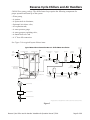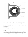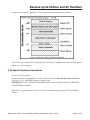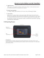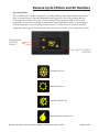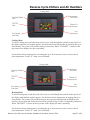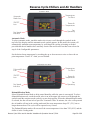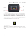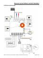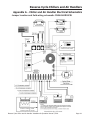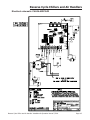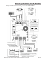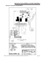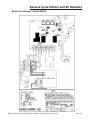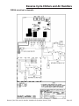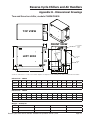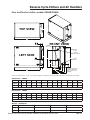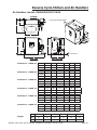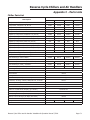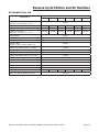
1
Reverse Cycle Chiller & Air Handlers
Chiller Models CHA24-36-48-60 and
Air Handler Models CWAH04-06-09-12-18-24
Installation and Operation Manual
Model CHA24 Reverse Cycle Chiller
Model CWAH12 Air Handler
Chapter 1 Introduction and Safety Information . ............................................................... 2
Chapter 2
Chiller Installation ........................................................................................... 3
Chapter 3
Air Handler Installation .................................................................................. 13
Chapter 4
Chiller Control ............................................................................................... 21
Chapter 5
Air Handler Control . ...................................................................................... 29
Chapter 6
System Start-Up ............................................................................................ 66
Chapter 7
Warranty ...................................................................................................... 67
Appendix A Electrical Schematics..................................................................................... A-1
Appendix B Dimensional Drawings...................................................................................B-1
Appendix C Parts List .....................................................................................................C-1
Manufactured by:
Marvair® Division of AIRXCEL®, Inc
PO Box 400 • Cordele, GA 31010
156 Seedling Dr. • Cordele, GA 31015
(229) 273-3636 • Fax (229) 273-5154
Email: [email protected]
www.marvair.com/marine
Marvair® Marine UK
Unit 6 Benridge Park • Holyrood Close
Poole, Dorset BH17 7BD.
+44 (0)1202 650700
www.marvair.co.uk
Part Number 01672
7/2011-5
Reverse Cycle Chillers and Air Handlers
Chapter 1
This is the safety alert symbol
. When you see this symbol on a Marvair® unit and in the instruction manuals be
alert to the potential for personal injury. Understand the signal word DANGER, WARNING and CAUTION. These
words are used to identify levels of the seriousness of the hazard.
DANGER
Failure to comply will result in death or severe personal injury and/or property damage.
WARNING Failure to comply could result in death or severe personal injury and/or property damage.
CAUTION Failure to comply could result in minor personal injury and/or property damage.
IMPORTANT is used to point out helpful suggestions that will result in improved installation, reliability or
operation.
1.1 General Description
Chillers
The Marvair line of reverse cycle chillers are self contained units designed for use with Marvair
chilled water air handlers. The units are available in multiple cooling capacities for operation on
various voltages and frequencies. The cupro-nickel heat exchanger is designed for use with sea
water or fresh water. The high efficiency flat plate heat exchanger for the loop water is designed
for use with a glycol solution. All units have factory installed paddle type flow switch to prevent
operation if there is not sufficient loop water flow. High and low pressure refrigerant access
valves are easily accessible behind the front panel. A factory installed well on the coupler on the
discharge chilled water line insures good contact between the temperature sensor and the coupler.
All models use the non-ozone depleting R-410A refrigerant and comply with all relevant CE
regulations.
IMPORTANT: The operating pressures of R-410A refrigerant are significantly higher than those
in R-22 systems. When checking refrigerant pressures, make sure the gauges are suitable for
R-410A refrigerant.
Air Handlers
The Marvair line of chilled water air handlers are available in multiple capacities for operation
on various voltages and frequencies. All the air handlers have an integral bleed valve connected
to the unit with a five foot (30.5 cm) flexible hose to facilitate purging the system. A unique
multiport discharge plenum allows for multiple duct connections and may eliminate the need
for “Y” or “T” adapters. A compact motorized impeller quietly moves the conditioned air while
drawing less amps when compared to centrifugal blowers. A motorized three way valve is
standard on all air handlers. Duct heaters are available as an option.
1.2 Chiller Model Identification
••
CH
A
CH - Chiller
RC
•
System Type
A = R410-A Nominal Capacity
Nominal Voltage
Refrigerant 24 = 24,000 BTUH RC = Reverse Cycle A =208/230V,1ø,60Hz
36 = 36,000 BTUH
C =208.230V,3ø,60Hz
48 = 48,000 BTUH
F =220V,1ø,50Hz
60 = 60,000 BTUH
W = 220/240V,1ø,50Hz
E = 380V,3ø,50Hz
Reverse Cycle Chiller and Air Handler Installation & Operation Manual 7/2011
•
Controls
S = Single Unit
M = Multiple Units
Page 2 of 68
Reverse Cycle Chillers and Air Handlers
1.3 Air Handler Model Identification
CWAH
Nominal Capacity
Chilled Water
Air Handler
04
06
09
12
18
24
=
=
=
=
=
=
4,000 BTUH
6,000 BTUH
9,000 BTUH
12,000 BTUH
18,000 BTUH
24,000 BTUH
Electrical Rating
A =208/230V,1ø,60Hz
B =115V,60Hz
F =220V,1ø,50Hz
W = 220/240V,1ø,50Hz
1.4 Standards and Codes
Various code and standards published by organizations are referenced in this manual. Some of the
organizations may be contacted in order to obtain complete copies of the code or standard.
American Boat & Yacht Council (ABYC)
613 Third St., Suite 10
Annapolis, MD 21403
Ph: (410) 990-4460
www.abyc.org
National Electric Code
National Fire Protection Association
1 Battery March Park
PO Box 9101
Quincy, MA 02269-9904
Chapter 2 - Chiller Installation,
Seawater piping, and Chilled Water Connections
2.1 Equipment Inspection
Concealed Damage
Inspect all cartons and packages upon receipt for damage during transit. Remove shipping cartons
and boxes and check for concealed damage. Important: Keep unit upright at all times. Inspect
refrigerant circuit for fractures or breaks. The presence of refrigerant oil usually indicates a
rupture in the refrigerant circuit.
Units that have been turned on their sides or upside down may have concealed damage to a
compressor, other components or to the refrigerant system. If the unit is not upright when you
receive it, immediately file a claim with the freight carrier for concealed damage and follow these
steps:
1.
2.
3.
4.
Set unit upright and allow to stand for 24 hours with primary power turned OFF.
After 24 hours, connect power to unit.
Attempt to start the unit after 24 hours.
If the unit will not start or makes excessive noise, return the unit to the freight carrier.
Reverse Cycle Chiller and Air Handler Installation & Operation Manual 7/2011
Page 3 of 68
Reverse Cycle Chillers and Air Handlers
WARNING
If the information in these instructions is not followed exactly, a fire, carbon
monoxide poisoning or explosion may result causing property damage, personal
injury or loss of life. • Read all instructions carefully prior to beginning
the installation. Do not begin installation if you do not understand any of
the instructions. • Improper installation, adjustment, alteration, service or
maintenance can cause property damage, personal injury or loss of life. •
Installation and service must be performed by a qualified installer, service agency
in accordance with these instructions and in compliance with all codes and
requirements of authorities having jurisdiction.
2.2 Chiller installation requirements
●●
●●
●●
●●
●●
●●
It is not recommended to install the chiller above an electronic or electrical panel, circuit breakers
or anything electrical. If installed above an electrical component a secondary drain pan must be
installed should condensate overflow the primary pan.
The chiller must be installed in a space with sufficient clearance for service. The chiller is
designed for zero clearance on the sides and the top – all access screws are on the front of the
unit. The screws are plated with a corrosion resistant black finish to standout against the white
cabinet for easy identification.. In the front, make sure there is sufficient room for condensate line
connections, seawater and chilled water line connections and electrical power.
The chiller should be level when installed, but will operate under normal pitch and roll in a boat.
The condensate line must at all times be lower than the base pan to allow all the condensate to
drain form the pan.
To save space & facilitate installation, the chiller has a detachable control box with a 6 ft. (1.8m)
cable harness. (Longer harnesses are available as a special order). The box can be mounted on top
of the chiller or on a bulkhead or rack mounted.
Bonding. To prevent corrosion due to stray electrical current or voltage, all metallic parts in
contact with water must be connected to the ship’s bonding system. This includes the chiller, all
pumps, metallic valves, fittings, strainers and thru-hulls. If any of these parts are isolated by PVC,
vinyl or rubber hoses, they must be individually bonded to the ship’s bonding system. Failure to
properly bond and ground the system in accordance with ABYC standard E-9, or equivalent, may
void the warranty and result in damage to the vessel and the chiller.
2.3 Chiller mounting and plumbing and electrical connections.
Mount the chiller inside a condensate pan and attach the chiller to the pan. The pan must be
secured to a surface of sufficient strength to with stand the dynamic forces when the boat is in
motion. Do not penetrate the bottom of the condensate base pan unless a free flowing drain is
properly secured to the pan. Any penetrations of the condensate pan must be made watertight.
Reverse Cycle Chiller and Air Handler Installation & Operation Manual 7/2011
Page 4 of 68
Reverse Cycle Chillers and Air Handlers
2.3.2 Water piping & connections
Chilled Water
Please see the chiller dimensional drawings for location and size of the sea water and chilled
water connections. For ease of service, unions and service valves (full flow type) are highly
recommended on all inlet and outlet water connections. For the chilled water system only
Schedule 80 PVC (Polyvinyl chloride) or type “L” copper pipe should be used. If using schedule
80 PVC (polyvinyl chloride) pipe, only solvent cemented joints should be used. Do NOT use
threaded connections due to insufficient wall thickness. (Verify that the pipe is suitable with
the anti-freeze solution used in the chilled water system.) Inadequate water flow and excessive
pressure are the result of pipe that is too small. Low water flow will result in the air handlers
not performing properly. See Figure 1, Recommended Chilled Water Pipe or Hose Size, shows
information for sizing the piping.
CAUTION
Do NOT use CPVC (Chlorinated Polyvinyl Chloride) pipe on the chilled water loop. In the event of a
rupture in the refrigerant to loop water heat exchanger, refrigerant oil can enter the chilled water loop.
The POE lubricating oil used in various compressors will aggressively attack CPVC pipe and cause
environmental stress cracks.
Attach flexible hose to the chilled water inlet and outlet fitting to eliminate vibration. This flexible
hose should be approximately 8” (20 cm) long with two, reversed hose clamps on each end of
the hose. Install a shut-off valve on both the inlet and outlet to isolate the unit for maintenance or
service.
Recommended Chilled Water Pipe or Hose Size
Chiller
Capacity
(BTUH/Hr x
1,000)
Chiller
Capacity
(kW/Hr)
Tons
GPM
(3 per ton)
4-21
24-45
48-81
84-129
132-225
228-405
408-600
1.2-6.2
7-13.2
14-23.7
24.637.8
38.7-66
66.8-118.7
119.5-175.8
1/3-1-¾
2-3¾
4-6¾
7-10¾
11-18¾
19-33¾
34-50
1-5¼
6-11¼
12-20¼
21-32¼
33-56¼
57-101¼
102-150
Liters/
3.8-21.8 22.7-42.6 45.4-78.5 79.5-124 124.9-212.9 215.9-383.3 386.1-567.8
Minute
Nominal
¾
1
1¼
1½
2
2½
3
Size (inches)
Nominal
Size (mm)
19.1
25.4
31.8
38.1
50.8
63.5
76.2
Figure 1
Reverse Cycle Chiller and Air Handler Installation & Operation Manual 7/2011
Page 5 of 68
Reverse Cycle Chillers and Air Handlers
Chilled Water pump package. The chilled water loop requires the following components for
proper operation and start-up of the system.
• Water pump,
• A strainer,
• A Spirovent® air eliminator,
• Spirotop® air release valve,
• An expansion tank,
• A water pressure gauge
• A water pressure regulating valve,
• A shutoff ball valve and
• A ¾” hose bib connection.
See Figure 2 for a typical layout of these items.
Typical Water Flow Schematic for Marvair® Chilled Water Installation
To Air
Handlers*
Loop Water Supply
Seawater Outlet
Service
Valve
Pressure Gauge
(0-50psi)
Circulation
Pump
Spirovent
From Air
Handlers
Y-Strainer
(20 Mesh)
Service
Valve
Seawater
Overboard
Drain
(at lowest
point in system)
Loop Water Return
(Return from
air handlers)
Seawater Inlet
Pressure Regulator (12psi)
Pressure Gauge
(and relief valve if needed)
(0-30psi)
Expansion
Backflow
Tank
Preventer
Fill Valve
Seawater Pump
Seawater Strainer
Seawater Inlet Valve
*Any pipe that rises vertically from the chiller should have an automatic air vent.
Figure 2
Reverse Cycle Chiller and Air Handler Installation & Operation Manual 7/2011
Page 6 of 68
Reverse Cycle Chillers and Air Handlers
Notes:
1. The minimum number of service valves to isolate the chiller equipment is shown. More valves
may be installed to isolate the strainer or pump or chiller separately, but this complicates the
system and can lead to operation confusion.
2. The Spirovent is shown in a simple in-line installation. This is not always possible due to flow
rates and the installation detail may be different. Refer to the Spirovent installation drawing for
more information.
3. If using an electric or fuel fired heater, a pressure relief valve should be installed on the fill line
for safety. A combination pressure relief valve/pressure regulator assembly is also available.
Chilled Water Flow Switch
Adjustment of the Chilled Water Flow Switch: Marvair chillers have a factory installed, paddle
type flow switch on the chilled water discharge line. If there is insufficient water flow, the
chiller will turn off to protect the air handlers. The red arrow should be barely visible on the
heat exchanger side of the switch when viewed from the top of the switch. See Figure 3 below,
Adjusting the setpoint.
Figure 3
Reverse Cycle Chiller and Air Handler Installation & Operation Manual 7/2011
Page 7 of 68
Reverse Cycle Chillers and Air Handlers
Chilled Water loop temperature sensors.
For accurate sensing of the chilled water temperatures, wells are factory installed on the chilled
water inlet line (return from the loop) and on the on the chilled water out line (supply to the
loop). The wells ensure accurate sensing of the water temperature by the temperature sensors.
The temperature sensor on the inlet (return) turns the chiller on & off, depending upon the water
temperature. If the chiller is in the cooling mode and the water temperature is above the set point,
the chiller will turn on to cool the loop water. If the chiller is in the heating mode and the water
temperature is below the set point, the chiller will turn on to heat the loop water.
The temperature sensor on the outlet pipe (supply) provides freeze protection and high limit
temperature conditions. To accurately measure the water temperature, the sensors must be fully
inserted into the wells. The sensors are coated with a heat transfer compound to ensure an
accurate sensing of the water’s temperature.
The ends of the sensor wires and the jacks on the control are color coded to facilitate the correct
placement of the sensors if they must be replaced. The loop supply (water out) is blue and the
loop return (water in) is red.
Seawater Piping
Proper seawater water flow is absolutely critical to the operation of the Marvair marine chiller
system. If the pipe is too small, back pressure is created causing a drop in water flow, even if
the pump is correctly sized. If the piping is too large, the slow velocity of the water may cause
silt build-up and barnacle growth inside the piping, eventually restricting water flow. See Figure
4, Recommended Seawater Pipe Sizes Figure 5, Seawater & Chilled Water Manifold Sizes, and
Figure 6, Seawater Manifold Orientation.
Recommended Seawater Pipe Size
Marvair Model
Pipe or Hose Size (ID)
CHA24
3/4” (19.1mm)
CHA36 & 48
1” (25.4mm)
CHA60
1-1/4" (31.75mm)
Figure 4
Seawater & Chilled Water Manifold Sizes
Chiller Capacity (tons)
4-10
11-18
19-33
Chiller Capacity (BTU/Hr x 1,000)
48-120
132-216
228-396
Chiller Capacity (kW)
14.1-35.2
38.7-63.3
66.8-116
Manifold & FPT Connection Size
1½”
2”
2½”
(38.1mm)
(50.8mm)
(63.5 mm)
34-50
408-600
119.5-175.8
3”
(76.2 mm)
Figure 5
Reverse Cycle Chiller and Air Handler Installation & Operation Manual 7/2011
Page 8 of 68
Reverse Cycle Chillers and Air Handlers
Seawater Manifold Orientation
More Flow
Equal Flow
Less
Flow
More
Flow
More
Flow
Less
Flow
More
Flow
Less
Flow
More
Flow
Less
Flow
INCORRECT
Less
Flow
CORRECT
Figure 6
The best material for seawater piping and fittings is cupronickel. Suitable materials for piping are
hi-grade bronze cupro-nickel and schedule 80 PVC (polyvinyl chloride) pipe. If using Schedule
80 PVC pipe, only solvent cemented joints should be used. Do NOT use threaded connections.
Materials to avoid are yellow brass, CPVC, poor grades of aluminum, stainless steel or steel pipe.
Use Teflon® tape or other appropriate sealant on all threaded fittings to prevent leaks.
CAUTION
Do NOT use CPVC (Chlorinated Polyvinyl Chloride) pipe on the chilled water loop. In the event of a
rupture in the refrigerant to loop water heat exchanger, refrigerant oil can enter the chilled water loop.
The POE lubricating oil used in various compressors will aggressively attack CPVC pipe and cause
environmental stress cracks.
Attach flexible hose to the chilled water inlet and outlet fitting. This flexible hose should be
approximately 8” (20 cm) long with two hose clamps on each end of the hose, fitted in reverse
directions. Shut-off valves are not required on the seawater lines, but a ball valve is required on
the seawater inlet.
Reverse Cycle Chiller and Air Handler Installation & Operation Manual 7/2011
Page 9 of 68
Reverse Cycle Chillers and Air Handlers
Marvair strongly recommends that only centrifugal pumps be used as the seawater pump. When
using a centrifugal pump, the Marvair reverse cycle chiller must be higher than the thru-hull
fitting, but lower than the heeled water line. The overboard fitting may be either higher or lower
than the unit. The tubing must never have any loops or kinks. If there is any place that water can
be trapped, damage may result during freezing temperatures. The pump and strainer must always
be below the heeled water line since centrifugal pumps cannot pump air. All fittings below the
water line must be secured with two reversed hose clamps (two hose clamps installed adjacent to
each other but facing in opposite directions).
Condensate
Condensation may form on exposed piping in the Marvair chiller. Therefore, the chiller must
be installed in a pan to collect the condensate. If a field supplied pan is not used, contact your
Marvair representative for a factory pan.
Thru-Hull Fitting
Install a scoop-type thru-hull fitting as close to the keel and as far below the water line as possible
to eliminate any possibility of air entering the system. Do not share the thru-hull with any other
device; i.e., an engine or generator. When using one thru-hull for multiple Marvair chiller, the
thru-hull must be sized for proper water flow. The scoop-type thru-hull should face forward. To
avoid air locks, the pipe from the thru hull must rise to the pump without any dips in the pipe. On
a fast planning boat, locate the thru-hull at the transom to ensure water flow.
Seacock
A bronze, full flow seacock or ball valve should be installed directly onto the thru-hull fitting.
The seacock must be closed to clean the strainer and in an emergency. Therefore, make it easily
accessible.
Strainer
The strainer must be installed so that it is always below the water line and below the pump. It
should be easily accessible for cleaning. Verify that the water flow is in the correct direction.
Secure the strainer to a bulk head.
Water Pumps
Centrifugal pumps must be mounted so that they are below the water line at all times. On sail
boats, the intake should be as close as possible to the keel. For service & maintenance, the pump
should be easily accessible. The pump should be installed with the outlet pointed upward so that
if air enters the system it can pass through the pump. The pump heads on some pumps can be
rotated to allow for mounting on a vertical surface. Self-priming pumps are available if the pump
cannot be installed below the water line. Pumps must be sized for the proper flow through the
seawater system. See Figure 7 for the minimum seawater flow rates and Figure 8, Pump Head
Orientation.
Reverse Cycle Chiller and Air Handler Installation & Operation Manual 7/2011
Page 10 of 68
Reverse Cycle Chillers and Air Handlers
Model
CHA24
CHA36
CHA48
CHA60
Minimum Seawater Flow Rates
Nominal Cooling Capacity Gal/Hr
2 tons
500
3 tons
750
4 tons
1,000
5 tons
1,250
Figure 7
Litres/Min
32
47
63
79
PUMP
HEAD
ORIENTATION
Pump
Head Orientation
CORRECT
CORRECT
INCORRECT
INCORRECT
Figure 8
Overboard Discharge
Ideally, the overboard discharge should be no more than 2” above the water line. This will
minimize sound yet allow visual confirmation of water flow. Marvair recommends a 90° scupper
fitting to direct the discharge down.
If the overboard discharge fitting must be installed below the water line, a valve must be installed
per ABYC standards. Note: if the overboard discharge must be installed below the water line, a
larger capacity pump (approximately 20%) will be required to overcome the back pressure from
pumping into the water. Also, a discharge below the water line makes cleaning muscles more
difficult.
Reverse Cycle Chiller and Air Handler Installation & Operation Manual 7/2011
Page 11 of 68
Reverse Cycle Chillers and Air Handlers
2.3.3 Electrical power connections
WARNING ELECTRICAL SHOCK HAZARD
Failure to follow safety warnings exactly could result in serious injury, death and or property
damage. Turn off electrical power at service panel BEFORE making any electrical connections
and ensure a proper ground connection is made before connecting line voltage.
All electrical work must meet the requirements of all applicable codes and ordinances. Work
should only be done by qualified persons.
If the wiring diagram that is on or was shipped with the unit is different from the one in this
manual, refer to and use the wiring diagram that is on or was shipped with the unit.
High Voltage Wiring (115V, 230V, 380V or 460V)
• The power supply must have the proper voltage, phase and ampacity for the selected model.
• Refer to the data label on the unit for field wiring requirements. The electrical data lists fuse and wire sizes for the unit.
• Each unit has a Minimum Circuit Ampacity (MCA). Field wiring must be used that is of sufficient size to carry that amount of current. Use copper conductors only. Refer to the National Electrical Code for complete current carrying capacity data on the various insulation grades of wiring materials.
• Power supply must be within allowable range of ±10% of rated voltage.
• The unit must be properly grounded to reduce the risk of shock or electrocution.
• A properly sized circuit breaker must be used. Information required to size the breaker is on the data sticker on the unit. If 230 volt 60 hz is achieved from 115 volt on line one and line 2, then it is essential that a double pole breaker is used. The breakers must be motor rated type B or, preferably type C.
• Connections between the ship’s alternating current grounding conductor and the ship’s negative or bonding system must be made as part of the ship’s wiring as per ABYC standard E-11 or equivalent.
• When servicing or replacing existing equipment that contains a chassis mounted ground lug, the service person or installed must verify the ship’s wiring for the connection required
in item f. above.
• All electrical connections must be made within the electrical junction boxes supplied with the unit. A terminal strip and/or electrical connectors are provided for component installation.
Display/Controller Wiring
The controller for the chiller operates on either a 115 or 230 VAC 50/60 hz. power supply.
Instructions for installing the thermostat/controller are detailed in Chapter 3.
Reverse Cycle Chiller and Air Handler Installation & Operation Manual 7/2011
Page 12 of 68
Reverse Cycle Chillers and Air Handlers
Chapter 3 - Air Handler Installation,
Ducting and Chilled Water System
CARBON MONOXIDE POISONING HAZARD
Never install air handlers in the bilge or a room with an internal combustion engine. The
condensate line must not terminate within three (3) feet (one meter) of the exhaust of any engine
or generator nor in any room that contains an engine or generator. Never install the air handler
in any room containing fuel tanks, LP/CPG cylinders regulators, valves or fuel line fittings.
3.1 Air Handler Installation Requirements
• Do not install the Marvair air handler in an engine room, the bilge or any areas where it may introduce deadly or noxious vapors into the boat’s living space.
• Do not install the air handler in any room or compartment that contains an internal combustion engine or in areas containing internal combustion engines, fuel tanks, LPG/CPG cylinders, regulators, valves or fuel line fittings.
• The condensate drain line must not terminate within three (3) feet of the exhaust of any engine or generator nor any room that contains an engine or generator. Under some circumstances, carbon monoxide can be pulled through the condensate tubing and introduced into the conditioned air.
• The condensate line must, at all times, be lower than the base pan. Consider installing a trap in the condensate line to prevent harmful gases or noxious vapors from being drawn into the conditioned air.
• It is recommended not to install the air handler above an electronic or electrical panel, circuit breakers or anything electrical. If installed in this or an overhead location, a secondary drain pan should be used.
• The air handler must be installed in a space with sufficient clearance on all sides for proper air circulation and for services. A minimum of three (3) inches must be provided from the face of the air coil to any obstruction, wall or bulkhead. Sufficient air flow is critical to the proper operation of the unit.
• Before placing the unit(s) into the space, make certain that there is sufficient room for all duct work, condensate line connections, water in and out, electrical power connections and control power connections.
3.2 Air Handler Installation
All Marvair air handlers have a 5' long factory installed remote air bleeder constructed of braided
hose with an integral relief valve for removing air from the system, a three-way motorized valve
with a factory installed water sensor and a remotely mounted electrical box.
Location
The air handler must be accessible for service and maintenance. The air filter must be periodically
checked and cleaned. The water connections should be easily reached. The electronic control
Reverse Cycle Chiller and Air Handler Installation & Operation Manual 7/2011
Page 13 of 68
Reverse Cycle Chillers and Air Handlers
board in the unit's electrical box must be accessible. Mount the air handler on a horizontal surface
and secure the condensate pan to the surface using the four clips that were provided with the air
handler. If the condensate pan is not properly secured, the blower housing may distort causing the
blower wheel to rub against the venturi ring..
Condensate
Marvair air handlers can produce significant quantities of condensate that may cause extensive
damage to the vessel if not disposed of properly. The base pan has two openings for condensate
drains. It is highly recommended that both of the openings be utilized – one for back-up in case
the other one becomes clogged or blocked. If only one is used, the other opening should be sealed
and plugged.
1.
Install the condensate drain fittings that were provided with the air handler through the base pan. Make sure the fitting is water tight.
2.
Attach a 5/8” ID reinforced hose to the hose barb and secure with two stainless steel hose clamps fitted in opposite directions.
3.
Route the condensate hose down from the air handler to a sump or to an overboard
fitting. If the drain runs overboard, it must not be within three (3) feet from the exhaust from the engine or generator. Double clamp all connections. If the condensate line is
run through a room or compartment containing an engine or fossil fueled device, it is
imperative that the line be air tight to prevent carbon monoxide other any other
hazardous gases or vapors from being introduced into the conditioned air system.
Electrical
Each air handler has its own electrical box. This box can be mounted remotely from the air
handler. Either 115V or 230V power (see data plate on the air handler) is required to operate the
air mover. A circuit board in the control box provides power to the wall mounted display.
Display
The display is used to select the set points for cooling and heating and to control the fan speed.
3.2 The Conditioned Air Duct & Grille System
The unique design of the Marvair air handlers with the multidirectional plenum allows duct to be
connected to the top or either side of the plenum. Please refer to Figure 9, Supply Duct Diameter
for the minimum size duct to use with the various air handlers.
Proper air flow is crucial to the operation of air handlers. The air distribution system must be
engineered to ensure sufficient air flow throughout the system. This includes proper duct sizing
and sufficient open area on the supply and return grilles.
Reverse Cycle Chiller and Air Handler Installation & Operation Manual 7/2011
Page 14 of 68
Reverse Cycle Chillers and Air Handlers
For optimum air circulation, it is good practice to install the supply air grilles near the top of
the cabin and the return air grille near the floor. This normally provides good circulation of the
conditioned air throughout the cabin. The location should provide easy access to the filter. If the
filter is not readily accessible, it probably will not be changed, shortening the life of the unit and
operating at less than designed performance. A filter grille is available if access to the filter on the
air handler is difficult to access. When using a return filter grille, always remove the filter on the
air handler - two filters should never be used.
Supply Air Duct Diameter (inches/mm)
CWAH04
4/102
CWAH06
5/127
CWAH09
6/152
CWAH12
6/152
CWAH18
7/178
CWAH24
8/203
Figure 9
3.2.1 Duct work guidelines
• Duct work must be firmly attached, secured and sealed to prevent air leakage.
• Use transition boxes and/or plenums with duct to split and route the conditioned air as required.
• Always use insulated duct. When installing insulated flexible duct, make sure that the inner duct is secured and sealed to an adapter before pulling the insulation over the connection.
• Install the supply air grilles high on the cabin wall to create good air circulation.
• Stretch the duct tight in straight runs.
• Make the bends and turns as large as possible. Secure the duct so that is remains in its installed position.
• Always use insulated duct to prevent condensation.
• Insulate all transitions and plenums.
• If duct is in a storage or other high traffic area, protect it from being crushed by a shield or box.
• If the duct must be run through areas containing engines or fossil fueled devices, it is absolutely mandatory that the duct system be air tight to prevent carbon monoxide and any other hazardous gases or vapors from being introduced into the conditioned air system. See ABYC Standard “A-6 Refrigeration and Air Conditioning Equipment” for more information on running duct through these areas.
Return Air Grille
The return air grille should be located to ensure unimpeded air flow to the air coil on the Marvair
air handler. The grille may be located on the opposite the coil provided there is a space around
the unit for sufficient air flow. Maintain sufficient space between the grille and the air handler,
preferably a minimum of 4” (10 cm). For good air distribution throughout the cabin, the return
grille should be located near the floor when the supply grilles are high on the cabin wall. The
Reverse Cycle Chiller and Air Handler Installation & Operation Manual 7/2011
Page 15 of 68
Reverse Cycle Chillers and Air Handlers
return air grille must have sufficient open air to permit adequate air to the air handler. The air
handler has cardboard placed over the coil to protect the coil during installation. The cardboard
must be removed and the filter installed prior to operating the air handler.
The Marvair air handler has a factory provided filter located in front of the air coil. If a return air
filter grille is used, it is recommended that the filter on the unit be removed. To ensure long life,
the coils on the air handlers are coated with a baked polyester finish rated to 1,000 hours when
tested to ASTM B117.
Supply Air Grille
The supply air grille must have sufficient open area to permit adequate air flow. To prevent short
circuiting of the conditioned air, adjust the vanes of the supply grille so that the discharge air is
not directed to the return air grille or to the thermostat/ controller.
Air Flow Noise
Air moving through duct work and across the blades in the grilles and louvers generates sound.
The faster the air, the greater the sound. To keep sound to acceptable levels, the cross sectional
area of the duct must be large enough to keep the velocity below 600 ft/min (3m/sec). Air flow
faster than this is likely to cause noise complaints. The duct sizes in Figure 9 are the minimum
size required to deliver the proper air flow without generating undue noise. Larger ducts will
have less friction and less noise. To minimize sound levels, position the motor of the air handler
adjacent to the return air grille, but not less than 4" (10 cm) from the grille.
Typical Air Handler Draw-Thru Installation
Figure 10
Reverse Cycle Chiller and Air Handler Installation & Operation Manual 7/2011
Page 16 of 68
Reverse Cycle Chillers and Air Handlers
3.3 Chilled water system piping guidelines.
The chilled water system is a closed loop circuit that connects the air handlers with the chiller.
Use Schedule 80 PVC (Polyvinyl Chloride) or type “L” copper pipe for the chilled water system.
If using schedule 80 PVC (polyvinyl chloride) pipe, only solvent cemented joints should be used.
Do NOT use threaded connections due to insufficient wall thickness. Inadequate water flow and
excessive pressure are the result of pipe that is too small. See Figure 11 for minimum chilled
water flow rates. Low water flow will result in the air handlers not performing properly. Figure
4 Recommended Seawater Pipe Size shows information for sizing the piping and Figure 1,
Recommended Chilled Water Pipe or Hose Size for minimum chilled water flow rates.
CAUTION
Do NOT use CPVC (Chlorinated Polyvinyl Chloride) pipe on the chilled water loop. In the event of a
rupture in the refrigerant to loop water heat exchanger, refrigerant oil can enter the chilled water loop.
The POE lubricating oil used in various compressors will aggressively attack CPVC pipe and cause
environmental stress cracks.
• All pipe must be completely insulated to prevent condensate from dripping from the pipe. All
insulation joints must be glued and the system should be air tight. The supply and return pipes
must be individually insulated with ¾” (19 mm) close cell foam insulation (Armaflex® or
equivalent). For chilled water pipes having a diameter of 1" (25.4 mm) or greater, the insulation
must be a minimum of 1" (25.4 mm) thick. For complete instructions on installing the pipe
insulation, please refer to the Armaflex installation manual. This manual can be downloaded
from the Armacell, LLC website at www.armacell.com.
• At no place should the insulation be compressed by the support system. Do not use tie wraps, hose clamps, collars or anything that would compress the insulation. See Figure 12 for a typical pipe support and insulation installation.
• After the system has been leak tested, all water fittings, valves, etc must be well insulated.
• The pipe system will weigh more when it is filled with water. The pipe must be supported properly for the additional weight.
• Use short radius elbows and fittings sparingly so as not to impede water flow.
• Take care during the installation of the system to prevent any debris from entering the loop. It is good practice to flush the system before filling the system.
Miminum Chilled Water Flow Rates
Model
Gals/Min.
Litres/Min
CHA24
6
23
CHA36
9
34
CHA48
12
45
CHA60
15
57
Figure 11
Reverse Cycle Chiller and Air Handler Installation & Operation Manual 7/2011
Page 17 of 68
Reverse Cycle Chillers and Air Handlers
Figure 12
Air Vents
Marvair recommends the use of air/water separators manufactured by Spirotherm, Inc. such as
Spirovent®. The Spirovent will remove air from the chilled water loop. It should be installed in
the main return line from the air handlers and before the chilled water circulating pump but after
the chilled water strainer and service valve.
The Spirovent has a threaded fitting to allow any water removed from the system to be discharged
into a condensate pan.
System Drain
A system drain should be placed in the lowest point of the system.
Air Vents
An air vent, such as a Spirotop® air release valve, should be installed wherever an air trap is
possible. Any pipe that rises vertically from the chiller should have an automatic air vent. This
includes every high point in the chilled water loop unless the high point is an air handler. (Marvair
air handlers have integral bleed valves air handler). The Spirotop has a threaded fitting to allow
any water removed from the system to be discharged into a condensate pan. Any air in the water
Reverse Cycle Chiller and Air Handler Installation & Operation Manual 7/2011
Page 18 of 68
Reverse Cycle Chillers and Air Handlers
line will prevent the flow switch to operate properly.
Testing the System
It is recommended to check the piping of the chilled water circulation system for leaks while it
is being installed. Testing the system after the system is complete may be difficult if fittings and
valves are behind walls or hard to access areas.
Flushing the chilled water system. After the chilled water system is complete, the system should
be flushed to remove any particles or contaminants in the system. Check the strainer for particles
and continue as necessary to remove all contaminants.
3.4 Filling and purging the chilled water system
The chilled water system MUST be a mixture of fresh water and anti-freeze to prevent freezing
of the pipes. Mix a water and anti-freeze solution according to the anti-freeze manufacturer’s
instructions. The freezing point of the antifreeze solution must not be more than 20°F (-6.7°C).
Use only a non-toxic, environmentally safe and friendly anti-freeze. Connect to the supply water
using an approved non-return valve supplied by Marvair to prevent contamination of the potable
water supply with glycol.
1. Flush the chilled water loop to remove any contaminants that may have entered the system
during installation.
2. Turn all circuit breakers to ON.
3. Fill the system from the main or potable water supply using a fill assembly. A fill assembly
consists of a pressure regulating valve and a backflow preventer. The backflow preventer
prevents the contamination of the potable water system with the glycol/water mixture. The
pressure regulator prevents over pressurization of the system.
4. In the programming mode, set the motorized valve in all the air handlers to Valve Override.
This opens all the valves.
5. When the system is full, turn on the chilled water system pump.
CAUTION
Failure to fill the system before running the pump may damage the pump.
6. One at a time, open the air bleed (Schrader) valve on each of the air handlers to allow air to
escape from the system. The pressure gauge should read between 12-15 psi. (Static pressure
will rise to 18-20 psi (1 bar) in normal operation.) Do not overcharge or the expansion tank
will not function properly.
7. When air ceases to escape from each of the bleeder valves, the air handlers are full. Tighten
the cap on the valve.
8. Check all fittings and connections for leaks. Make sure pressure is between 12-15 psi.
The system has now been filled with fresh water and tested to be free of leaks. At this time the
anti-freeze or glycol is added to the fresh water.
Reverse Cycle Chiller and Air Handler Installation & Operation Manual 7/2011
Page 19 of 68
Reverse Cycle Chillers and Air Handlers
9. Determine the proper quantity of anti-freeze or glycol to add to the system according to the
anti-freeze or glycol manufacturer’s instructions. Typically, the minimum is a 20% antifreeze solution, but a higher percentage is required in cold climates.
10. Remove the pressure from the system at the drain point (in the engine room).
11. Go to the highest accessible air handler, remove the Schrader valve and place the flexible
hose from the air handler into a container with the required amount of glycol or antifreeze.
12. At the drain point in the engine room, remove an equal amount of water as the amount of
glycol or anti-freeze as determined in step nine. This will siphon the anti-freeze glycol into
the loop system. When all the anti-freeze or glycol has been siphoned into the loop, close
the drain valve.
13. At the highest accessible air handler, remove the flexible hose from the container and
reinstall the Schrader valve.
14. Repressurize the system using the pressure regulation valve and the backflow preventer
(fill assembly). The valve ensures that the system is properly pressurized and the backflow
preventer does not allow the anti-freeze mixture to contaminant the fresh water system.
Make sure the static pressure is between 12-15 psi. (Note: when system is running, pressure
will be 18 to 20 psi.)
15. Run the loop circulation pump for 15 minutes to insure that the glycol or anti-freeze is
dispersed throughout the loop.
16. Verify that the seawater valve is open.
The system is now ready to operate. To operate the chiller and air handlers, refer to the start up
instructions for the display/controller installed in the boat.
Reverse Cycle Chiller and Air Handler Installation & Operation Manual 7/2011
Page 20 of 68
Reverse Cycle Chillers and Air Handlers
Chaper 4 - Chiller Control
4.1 General Description
The MARVAIR® CHILLER digital control operates Marvair chillers to provide closed loop water
temperature control. The MARVAIR® CHILLER digital control is designed to operate with a
reverse cycle, chilled water marine air-conditioning system.
Features include:
• High visibility Organic Light Emitting Diode display (OLED) offers superior visual characteristics compared to LCD displays.
• Variable brightness adjustment and automatic screen saver.
• Four position menu navigation switch featuring a joystick style interface with push on / push off control.
• The display is compatible with Vimar and Gewiss frames.
• Visual symbols enable the viewer to see the operating status at a glance.
• Easily configured for customized operation.
• Built in options for fault protection help aid trouble diagnosis and prevent system damage.
• Universal 115/230 VAC 50/60 Hz power supply
Before you start:
For installations with two chillers, one of the chillers must be designated as Chiller No. 1 and the
other as Chiller No. 2. To designate a chiller as Chiller No. 1, go to the PC board for a chiller. J8
on this board must be jumped, i.e., there must be continuity between the 2 pins.
To designate the other chiller as Chiller No. 2, J8 on its PC board must NOT be jumped. With JP8
removed, the second unit will operate at a different default set point and staging delay.
Make sure both chillers are in the same operating mode. One chiller must not be in cooling and
the other in heating.
Reverse Cycle Chiller and Air Handler Installation & Operation Manual 7/2011
Page 21 of 68
Reverse Cycle Chillers and Air Handlers
Applying power:
When power is first applied, the display will show the software revision, and then return to the last state the unit was in when power was removed.
Up Button
On/Off Button
Mode Select
Button
Service Button
(Unmarked)
Down Button
Joystick operation:
The four position joystick may be tapped up, down, right, left or in the center to make changes to the operation of the control. Gently tap this switch to operate it. Excessive force will damage the switch.
Operating states:
Pressing the joystick in the center will toggle between OFF and ON. When the display is OFF the display will appear dark. When the display is ON, the display shows the operating screen. See operating screens for an example. Switch between these states by pressing and releasing the On/Off button. Unless screen saver is active. See screen saver for details.
4.2 Operating Screens
Screen Saver
If no buttons are pressed for two minutes, the display will enter the screen saver mode. The
display will dim and “MARVAIR” will scroll across the screen. To exit this mode, just tap any
button.
Reverse Cycle Chiller and Air Handler Installation & Operation Manual 7/2011
Page 22 of 68
Reverse Cycle Chillers and Air Handlers
Operating Screen
Water Inlet Temperature
Temperature Set Point
Water Outlet Temperature
Operating Status Graphic
Heating
or
Cooling
4.3 Mode Selection
To change from heating to cooling or cooling to heating, tap the mode select icon. Set the
desired loop water temperature by tapping the up or down icon. The system will provide cooling
or heating as selected. For installations with two chillers, both chillers MUST be in the same
operating mode, i.e., Cooling or Heating. One chiller can not be in Cooling and the other in
Heating.
Operation
The control will automatically operate the circulating pump, sea water pump, compressor and
heater or valve as necessary. Inlet temperature must be more than two degrees from the set
point for operation to occur. In heat mode, temperatures must be below set point and in cool
mode temperatures must be above the set point. Temperatures must be above 33°F (1°C) for any
operation. Operating output conditions are indicated in the graphic at the center of the display.
CW is the closed circulating water loop. When the pump is on, the graphic will animate and
show water flow in the system. If the flow switch opens, or the pump is off, the pipe will
appear empty.
This is the compressor symbol. When the compressor is running, the symbol will look like
an operating piston.
SW is the sea water pump. When the pump is on, the symbol will animate and show the
pump operating and water flowing. When the sea water pump is off, the pipe will appear
empty and the pump will not spin.
This is the electric heat symbol. This symbol will appear in heat mode in place of the
compressor if the optional electric heater is installed and selected in the programmable
parameters. The animation will look like heat rising from the element when the heater is on.
Reverse Cycle Chiller and Air Handler Installation & Operation Manual 7/2011
Page 23 of 68
Reverse Cycle Chillers and Air Handlers
System Status Screen
AC Line Voltage
Switch
System Current
Switch
System
Frequency
High Refrigerant
Pressure
(CLosed or OPen)
Low Refrigerant
Pressure
(CLosed or OPen)
Flow Switch
(CLosed or OPen)
Viewing System Status
In the ON state, press and hold the Mode select icon for three seconds. The display will indicate
AC line voltage, System current, AC Line frequency, and High and Low pressure switch status
and Flow switch status. After one minute without a button press, the display will return to the
operating screen.
Viewing Fault History
Fault message history may be viewed by pressing and holding the service icon for three seconds
with the display in the operating screen. Scroll from message to message by tapping the up and
down icons. The past eight fault messages, numbered from 1 to 8 can be viewed with the most
recent numbered 1. Multiple faults of the same type will not be listed separately unless they occur
more than one hour from the first fault. To clear the history log, the screen must show the operate
screen. Press and hold the service icon for 10 seconds. The history log will appear then the
displayed fault will disappear indicating the log is cleared.
Fault Messages
The following fault messages will be shown on the display in the event of a problem. Compressor
and electric heat operation is prevented for two minutes after a fault occurs. Repeated faults are an
indication of a problem and should be checked by a qualified service person.
LOCKOUT: Four of the same faults occurred in less than 1 hour from the first fault. The display
will show the fault that caused the lockout followed by the word “LOCKOUT”. Press the On/Off
icon on the display to clear a lockout. HIGH REFRIGERANT PRESSURE: Indicates the high pressure switch connected to the High/
Low refrigerant jack is open. If the switch resets, the compressor will restart within two minutes.
LOW REFRIGERANT PRESSURE: Indicates low pressure switch connected to the High/Low
refrigerant jack is open for over 10 minutes. The LP jumper (JP7) on the board must be cut or not
jumpered to enable this option.
Reverse Cycle Chiller and Air Handler Installation & Operation Manual 7/2011
Page 24 of 68
Reverse Cycle Chillers and Air Handlers
LOW AC VOLTAGE: The AC line voltage was below the voltage set in the programmable
parameters for more than 10 minutes.
OVER CURRENT: The total system run current exceeded the limit set in the programmable
parameters. Systems may start with currents exceeding the limit but must be below the limit
within two seconds after the start of the compressor.
FREEZE FAULT: The closed circulating loop water temperature at the water outlet sensor is
below 34°F (1.1°C). This fault causes an immediate lockout for system protection.
FLOW SWITCH OPEN: The closed circulating water loop flow switch connected to the service
input is open for more than 10 seconds. When this fault occurs, all outputs will shut down for two
minutes then restart.
SENSOR TROUBLE WATER IN: The sensor connected to the ALT AIR jack (Loop water in) has
failed or is disconnected.
SENSOR TROUBLE WATER OUT: The sensor connected to the OUTSIDE jack (Loop water out)
has failed or is disconnected.
HIGH LIMIT: Closed circulating loop water outlet temperature has exceeded the limit set in the
programmable parameters.
4.4 Configurable Parameters:
There are eleven configurable parameters with their factory defaults described in this section.
The table below defines the parameter descriptions along with the permitted values and default
settings.
To enter the configuration mode first put the unit in the OFF state. Next press the following
sequence of icons: Mode, Up, Down, Mode. (On versions B19 and later, the configuration mode
can be entered by pressing the center of the button for 10 seconds.) Use the service icon to
advance to the next parameter and the mode icon to go back to the last parameter. Use the up
and down icons to change the parameters value. Exit the configuration mode when finished by
pressing and releasing the On/Off icon or wait 60 seconds for the display to exit.
Reverse Cycle Chiller and Air Handler Installation & Operation Manual 7/2011
Page 25 of 68
Reverse Cycle Chillers and Air Handlers
Description
Default
Value
Display brightness
15
4=Minimum 15=Maximum
Screen Saver Brightness
4
0=Minimum 8=Maximum
Staging Delay
15 or 45*
5-135 Seconds
Current Limit
35
0-35 Amps (0 is disabled)
Low AC Line Detection
Off
75-100 or 175-200 VAC
High Limit Threshold
130°F (54.4°C)
100-135°F (38°C - 57°C)
System Units
°F
°F or °C
Cycle Sea Pump
Cycled Sea Pump
Cycled or Continuous
Reverse Cycle Heat
Reverse Cycle Heat
Electric Heat or Reverse Cycle Heat
Purge Air in System
No
Yes or No
Reset Parameters
No
No or Yes
If JP8 is removed, Staging Delay default will be 45 seconds.
Parameter description:
• Display brightness: Display brightness can be set from 4 (dim) to 15 (bright) to suit room lighting. Brightness will change as the number is changed.
• Screen saver brightness: Number values from 0 (dim) to 8 (bright) can be set to suit room brightness. The unit will operate as described in the screen saver section.
• Staging delay: The compressor staging delay is provided for multi-system installations where more than one system is operating from the same power source. Set the Staging delays at different intervals so only one compressor starts at a time when power is applied.
• Current limit: The system current limit can be set from 0 to 35 Amps maximum running
current. Systems may start at higher currents but running currents must be less than the set point. To disable this fault set the limit to 0.
• Low AC line detection: When set, if the AC line voltage remains below the set value for 10 minutes, the control will turn off the compressor or heater and indicate Low AC. Voltages may be set between 75 and 100 VAC for 120 volt systems, and 175-200 VAC for 208-230 VAC systems.
• High Limit Threshold: Set this parameter to monitor water outlet temperature. Temperatures may be selected between 100°F and 135°F (38°C and 57°C).
• System units: Degrees Fahrenheit (°F) or degrees Celsius (°C) can be selected
• Cycled Sea Pump: This setting will turn on the sea pump with the compressor. This parameter may be changed to run the Sea Pump continuously.
• Electric Heat/ Reverse Cycle Heat: Set this parameter only if the system is equipped with an electric heater. If the heater current will exceed 10 Amps, a contactor must be connected to the valve output to use this feature.
• Purge Air in System: This parameter allows the user to operate the circulating pump for one hour while the system is being filled so air can be removed. Set the parameter to YES and press the On/Off button. The display will go blank then the screen saver will appear with “PURGING AIR” on the screen. The circulating loop water pump will run for 1 hour then turn off. To exit Reverse Cycle Chiller and Air Handler Installation & Operation Manual 7/2011
Page 26 of 68
Reverse Cycle Chillers and Air Handlers
this function, press the On/Off button. Flow faults are disabled while Purge Air is active. Flow switch status may be viewed in the system status screen. See Viewing System Status for details.
• Reset parameters: To reset all parameters to factory defaults, select YES and then exit the program mode by pressing the joystick center button. The display will show EEPROM RESET then the display will go blank indicating the unit is OFF.
Staging two compressors in a system:
In some applications, two compressors may be necessary to handle the cooling or heating load.
On these systems, remove jumper JP8 from one of the two power supplies. (see Wiring Diagram
and Configuration for jumper location details). With JP8 removed, the second unit will operate at
a different default set point and staging delay.
Defaults:
JP8 In: Cool 42°F (5.5°C), Heat 110°F (43.3°C), Staging Delay 15 Seconds
JP8 Out: Cool 44°F (6.7°C), Heat 108°F (6.1°C), Staging Delay 45 Seconds
The default values can be changed in the Normal Operating mode.
4.5 Specifications
Set point range:
Cool Mode: .............................................................................. 38°F-58°F
3.3°C-14.4°C
Heat Mode: .............................................................................. 95°F to 120°F
35°C to 48.9°C
Sensor accuracy: ...................................................................... 2°F at 77°F
1°C at 25°C
Low voltage limit 115 VAC units: . ......................................... 75VAC
Low voltage limit 230 VAC units: .......................................... 175VAC
Line voltage limit: ................................................................... 240VAC
Frequency: ............................................................................... 50 or 60 Hz
Fan output MAX (Connect to Sea Water Pump): ................... 4 Amps
Valve output MAX (Connect to optional electric heater): ...... 10 Amps
Reverse Cycle Chiller and Air Handler Installation & Operation Manual 7/2011
Page 27 of 68
Reverse Cycle Chillers and Air Handlers
Circulating Pump output MAX:............................................... ¼ HP at 115 VAC
½ HP at 230 VAC
Compressor output MAX:........................................................ 1HP at 115 VAC
2HP at 230 VAC
Minimum operating temperature: . .......................................... 0°F
-18°C
Maximum operating temperature: ........................................... 180°F
82°C
Maximum RH conditions: ....................................................... 99% Non-condensing
Maximum length of the display cable: .................................... 75 Feet (23m)
Maximum length of the sensor cable: ..................................... 50 Feet (15m)
Reverse Cycle Chiller and Air Handler Installation & Operation Manual 7/2011
Page 28 of 68
Reverse Cycle Chillers and Air Handlers
Chapter 5 - Chilled Water Air Handler Control and Display
General Information
There are two control kits for the Marvair chilled water air handlers – one with the MachAir I
display and the other with the o-LED display.
The control boxes for each kit is identical except for the position of the jumpers on the board.
(The jumpers can be repositioned in the field). The boards are sent from the factory with the pins
in the position for the o-LED or o-Touch display. Instructions for moving the pins to use with the
MachAir I display are described beginning in section 5.5. Packaged in each kit are the following:
1.
2.
3.
4.
5.
6.
The board mounted in a white, corrosion resistant aluminum electrical box
Either the o-LED, o-Touch or the MachAir I display
A 10 ft. long display cable to attach the display to the board
A 7 ft. long sensor cable to measure the loop supply temperature.
A 7 ft. long sensor cable to measure the ambient air temperature. This sensor is mounted on
the front of the air handler coil to sense ambient air temperature
The o-LED display kit includes a black Vimar bezel and mounting plate
In the cooling mode when the ambient room temperature is above the set point temperature and
the loop supply temperature is below the set point temperature, the three way valve and blower
are energized to provide cooling to the room. In the heating mode when the ambient temperature
is below the set point temperature and the loop supply temperature is above the set point
temperature, the three way valve and blower are energized to provide heating to the room.
The boards have a blue and red dot above the sockets for the sensor cable.
• Blue is for Supply-Loop Temperature cable and
• Red is for the Return-Air Ambient Air Temperature cable. Reverse Cycle Chiller and Air Handler Installation & Operation Manual 7/2011
Page 29 of 68
Reverse Cycle Chillers and Air Handlers
The ends of the cables are color coded to ensure that the cables are correctly connected to the
board. Sections 5.1- 5.4 describe the configuration and operation of the o-LED display. Sections
5.5– 5.14 describe the configuration and operation of the MachAir I controller. Section 5.15 - 5.20
describe the configuration and operation of the o-Touch controller.
5.1 General Description
The Marvair® digital controller for chilled water air handlers allows for easy adjustment of fan
speed, operating mode and temperature in a compact, easily readable display. The digital control
is designed to operate with Marvair marine chilled water air handlers.
Features include:
• Four position menu navigation switch featuring a joystick style interface with push on / push off control.
• Built in room temperature sensor.
• The display is compatible with Vimar and Gewiss frames.
• Visual symbols enable the viewer to see the operating status at a glance.
• Easily programmed for customized operation.
• Both automatic and manual six level fan speed adjustment.
• Universal 115/230 VAC 50/60 Hz power supply.
Optional features include:
• Outside air temperature sensor.
• Alternate air sensor.
Before you start:
For installations with two chillers, one of the chillers must be designated as Chiller No. 1 and the
other as Chiller No. 2. To designate a chiller as Chiller No. 1, go to the PC board for a chiller. J8
on this board must be jumped, i.e., there must be continuity between the 2 pins.
To designate the other chiller as Chiller No. 2, J8 on its PC board must NOT be jumped. With JP8
removed, the second unit will operate at a different default set point and staging delay.
Make sure both chillers are in the same operating mode. One chiller must not be in cooling and
the other in heating.
Applying power:
When power is first applied, the display will show the software revision, and then return to the
last state the unit was in when power was removed.
Reverse Cycle Chiller and Air Handler Installation & Operation Manual 7/2011
Page 30 of 68
Reverse Cycle Chillers and Air Handlers
Up Button
On/Off Button
Mode Select
Button
Fan Operation
Button
Down Button
Joystick operation:
The four position joystick may be tapped up, down, right, left or in the center to make changes to
the operation of the control. Gently tap this switch to operate it. Excessive force will damage the
switch.
Operating states:
The display operates in two operational states. In the OFF state, the temperature is displayed and
only fan operation is available. In the ON state, the display shows the temperature set point, room
temperature, fan, and valve status. Switch between these states by pressing and releasing the On/
Off icon.
5.2 Operating Screens
Screen Saver
Room
Temperature
Cool Mode
Symbol
Fan Operating
Valve Status
Screen Saver
In screen saver, the display will appear dim and the information will scroll across the screen.
Status symbols appear as needed and operation continues in the mode selected. To exit this mode,
just tap any icon.
Reverse Cycle Chiller and Air Handler Installation & Operation Manual 7/2011
Page 31 of 68
Reverse Cycle Chillers and Air Handlers
Cool Mode
Room Air
Temperature
Temperature
Set Point
Cool Mode
Symbol
Valve Status
Automatic Fan
Mode
Fan Operating
Cool mode
To select cooling only, tap the mode select icon to scroll through the symbols in the top left of
the display until the cool symbol appears. Set the desired room temperature by tapping the up or
down icon. The system will provide cooling as necessary. The valve symbol will appear when
system is cooling.
Heat Mode
Room Air
Temperature
Temperature
Set Point
Heat Mode
Symbol
Valve Status
or
Electric Heater
Fan Operating
Fan Speed Indicator
Heat mode
To select heating only, tap the mode select icon to scroll through the symbols in the top left of
the display until the heat symbol appears. Set the desired room temperature by tapping the up or
down icon. The system will provide heating as necessary. The valve or electric heat symbol will
appear when the system is heating.
Reverse Cycle Chiller and Air Handler Installation & Operation Manual 7/2011
Page 32 of 68
Reverse Cycle Chillers and Air Handlers
Automatic Mode
Room Air
Temperature
Temperature
Set Point
Automatic Mode
Symbol
Valve Status
Fan Operating
Fan Speed Indicator
Automatic Mode
To select automatic mode, tap the mode select icon to scroll through the symbols in the top left of
the display until the automatic mode symbol appears. In this mode, the system will automatically
maintain room temperature. Set the desired room temperature by tapping the up or down joystick
icon. When the system is operating, the appropriate symbol will appear in the lower left corner.
Manual Fan Low
Manual Fan High
Animated
Symbol
Fan Speed
Indicator
“M” = Manual Fan
Fan Operation Button
Operating the fan
Fan speed may be controlled automatically by room temperature or manually. Tap the joystick
fan button to cycle through fan speeds and automatic operation. Manually selected fan speed
is indicated with the M showing before the speed indicator. When the fan is automatically
controlled, the M is not present. The fan may be controlled in the cool, heat, automatic modes as
well as in the off state to circulate room air.
Manual fan speed operation is not available when the water valve is not open if the cycle fan
option is set. Turn the unit off in this case and then manual fan operation may be used.
Reverse Cycle Chiller and Air Handler Installation & Operation Manual 7/2011
Page 33 of 68
Reverse Cycle Chillers and Air Handlers
Outside Air Temperature
If the optional outside air temperature sensor is installed, the temperature set point in the upper
right of the display will alternate with OAT showing outside air temperature.
System Status
AC Line Voltage
System Current
AC Line
Frequency
Loop Water
Temperature
Viewing System Status
In the ON state, press and hold the Mode select icon for two seconds. The display will indicate
AC line voltage, System current, AC Line frequency, and loop water temperature. If the loop
water sensor is not installed or fails, no reading will appear. In this case, electric heat will not
be available and the system will open the valve when necessary regardless of loop temperature.
If the inlet (return) loop water temperature shown on the chiller display is the same as the air
temperature shown on the air handler display, then the loop water temperature sensor is not
properly installed. See section 2.3.2, "Loop water temperature sensors".
Air Sensor Trouble
If the air sensor fails, AIR SENSOR TROUBLE will appear on the display. The air sensor should
be checked by a qualified service person.
5.3 Configurable Parameters
There are eleven configurable parameters with their factory defaults described in this section.
The table below defines the parameter descriptions along with the permitted values and default
settings.
Reverse Cycle Chiller and Air Handler Installation & Operation Manual 7/2011
Page 34 of 68
Reverse Cycle Chillers and Air Handlers
To enter the configuration mode, first put the unit in the OFF state. Next press the following
sequence of icons: Mode, Up, Down, Mode (or by pressing and holding the center of the button
in for 10 seconds). Use the fan icon to advance to the next parameter and the mode icon to go
back to the last parameter. Use the up and down icons to change the parameters value. Exit the
program mode when finished by pressing and releasing the On/Off icon or wait 60 seconds for the
display to exit.
Description
Cycled Fan
Reverse Fan in Heat
System Units
Display Brightness
Screen Saver Brightness
Temperature Calibration
Alternate Air Enabled
Default
Continuous
Reverse
°F
15
4
0
Alternate Air Enabled
Electric Heat
No Electric Heat
Normal Valve Operation
Normal Valve Operation
Fan Speed 1
Fan Speed 2
Fan Speed 3
Fan Speed 4
Fan Speed 5
Fan Speed 6
Reset Parameters
30
35
40
45
55
85
No
Value
Cycled or Continuous
Reverse or Normal
°F or °C
4=Minimum 15=Maximum
- and 1-8
Ambient +/- 10°F
Alternate Air Enabled or
Outdoor Air Enabled
Electric Heat or
No Electric Heat
Normal Valve Operation or
Valve Override
30-90
30-90
30-90
30-90
30-90
30-90
No or Yes
Parameter Description
oCycled Fan: When set for cycled, the fan will operate on demand. When set for continuous, the fan will always run unless the system off is turned off.
oReverse Fan in Heat: Fan speed will increase as the room temperature rises if this parameter is set for reverse. If set for normal, fan speed will decrease as room temperature rises. This parameter only works in heat mode and the fan must be set for automatic operation.
oSystem Units: Degrees Fahrenheit (°F) or degrees Celsius (°C) can be selected
oDisplay Brightness: Display brightness can be set from 4 to 15 to suit room lighting. Brightness will change as the number is changed.
oScreen Saver Brightness: If set for (-) than a single bar (-) will blink sequentially in the four corners of the display. Number values from 1 to 8 can be set to suit room brightness and the unit will operated as described in the screen saver section.
o Temperature Calibration: This parameter allows the user to calibrate the room air temperature
sensor. The room temperature will be displayed and can be adjusted +/-10 °F or +/-5°C
Reverse Cycle Chiller and Air Handler Installation & Operation Manual 7/2011
Page 35 of 68
Reverse Cycle Chillers and Air Handlers
oAlt Air Enabled: When set for alt air enabled, the alternate air jack can be used with an optional air sensor to replace the display mounted air sensor. When set for outside air enabled, an optional sensor may be installed to monitor out side air temperature. This will appear as OAT on the display.
oElectric Heat/ No Electric Heat: Set this parameter only if the system is equipped with an electric heater. The electric heater is connected to the compressor L1 and compressor L2 terminals. Heater current must not exceed 30 Amps.
oNormal Water Valve Operation: This feature allows service personnel to force the water valve
open to facilitate bleeding air from the system. Selecting override will force the water valve open for four hours. This operation can be reset by turning the system on with the On/Off button.
oFan Speed 1-6: These parameters are used to optimize fan performance and should be changed only by qualified service personnel.
oReset Parameters: To reset all parameters to factory defaults, select YES and then exit the program mode by pressing the joystick center button. The display will show EEPROM RESET then show the room temperature in the off mode.
5.4 Specifications
Set point range.......................................................................... 55°F to 85°F
12.7°C to 29.4°C
Ambient temperature range displayed...................................... 5°F to 150°F
-15°C to 65.5°C
Sensor accuracy........................................................................ 2°F at 77°F
1°C at 25°C
Low voltage limit 115 VAC units . .......................................... 75VAC
Low voltage limit 230 VAC units............................................. 175VAC
Line voltage limit...................................................................... 250VAC
Frequency.................................................................................. 50 or 60 Hz
Fan output MAX....................................................................... 6 Amps
Valve output MAX.................................................................... 10 Amps
Heater output (connected to compressor L1 and L2)............... 30 Amps Maximum
Reverse Cycle Chiller and Air Handler Installation & Operation Manual 7/2011
Page 36 of 68
Reverse Cycle Chillers and Air Handlers
Minimum operating temperature.............................................. 0°F
-18°C
Maximum operating temperature............................................. 180°F
82°C
Maximum RH conditions......................................................... 99% Non condensing
Maximum length of the display cable ..................................... 75 Feet (23m)
Maximum length of the Outside air sensor cable..................... 50 Feet (15m)
5.5 MachAir I Display/Controller General Description
The MachAir I controller/display is designed for use with Marvair Chilled Water Air Handlers.
The MachAir I controller/display has a universal power supply that operates on 115, 230, 50 or 60
Hz AC power. The MachAir I Air Handler controller/display includes the following standard and
optional features:
Standard Features
• Paintable Face Plate Cover with recess for matching wall covering insert.
• User friendly 6 button display panel requires no manual for basic operation.
• Five volt logic and micro controller located in the display.
Reverse Cycle Chiller and Air Handler Installation & Operation Manual 7/2011
Page 37 of 68
Reverse Cycle Chillers and Air Handlers
• 3-digit, 7-segment display indicates °Fahrenheit or °Celsius.
• Automatic fan speed reduction as set point is approached.
• Six [6] manual fan speeds.
• 18 programmable parameters for custom installations.
• Water In sensor allowing individual cabin heating.
• Moisture Mode for controlling relative humidity.
• Universal 115/230 VAC power supply.
• Non-volatile memory retains settings without batteries.
• Programmable display brightness control for night use.
Optional Features
The following optional items can be added by plugging the device into the appropriate jack and
making the necessary programming changes.
• Outside air temperature sensor.
• Alternate air temperature sensor.
• Custom Polished Brass Display Panels.
• Electric Heat Option.
These instructions is intended to provide information necessary to insure proper installation
and operation of the MachAir I Air Handler controller/display. Poor installation and
MISUNDERSTOOD operating parameters will result in unsatisfactory performance and
premature failure of the controller/display.
5.6 Basic Operation
Controller Overview
Auto Mode LED
Cool Mode LED
Heat Mode LED
Display
Water Valve
Status LED
Mode
Moisture
Control LED
Fan
Fan Speed
Bar Graph
Auto Fan LED
Manual Fan LED
Power
Temp Select
Down
Reverse Cycle Chiller and Air Handler Installation & Operation Manual 7/2011
Page 38 of 68
Reverse Cycle Chillers and Air Handlers
Power Button: Press the power button once to toggle the unit to the on mode. Press the power
button again to toggle the unit to the off mode.
Fan Button: Press and release the fan button to advance from auto to manual fan. Press and
release to increase the manual fan speeds, 1 through 6. Press and release again returns to the auto
fan mode. The selected fan mode is indicated by the Auto and Manual fan LED's UP BUTTON
Momentarily press and the set point will appear in the temperature display. The set point increases
one degree each time the up button is pressed and released.
Down Button: Momentarily press and release to display the set point. The set point is decreased
one degree each time the down button is pressed and released.
Mode Button: The mode button is used to select one of four Operating Modes. Press and release
to advance to the next mode. Continue to press and release until the desired Operating Mode is
reached. The mode selected is indicated by the Mode LED.
Temp Select Button: Press and release to view inside air temperature, outside air temperature or
set point. The appropriate LED will be lit indicating the temperature is displayed.
Three Digit Display: The room temperature is displayed whenever the control is turned on. The
display provides a readout of the inside ambient air temperature and the set point.
Heat Mode LED: The heat mode LED is lit when Heating is selected.
Cool Mode LED: The cool mode LED is lit when the Cooling is selected.
Auto LED: The auto LED is lit when the Automatic Heating or Cooling Mode is selected. The
control will automatically switch to heating or cooling when this mode is selected.
Moisture Control LED: The moisture LED is lit when the Moisture Control is selected.
Manual Fan LED: The manual fan LED is lit when a manual fan speeds is selected.
Auto Fan LED: The auto fan LED is lit when automatic fan speed operation is selected.
Fan Speed Bar Graph: There are six [6] individual fan speed LED's. Each LED represents one
[1] fan speed. Low fan [1] is indicated by illuminating the first LED. High fan speed is indicated
by illuminating all six [6] LED's.
Water Valve Status LED: The system operating status [ Water Valve Open or Closed ] is
indicated by turning On the right most decimal point in the 3 Digit Display.
Reverse Cycle Chiller and Air Handler Installation & Operation Manual 7/2011
Page 39 of 68
Reverse Cycle Chillers and Air Handlers
5.7 Overview of the operation
The MachAir I controller/display is a user friendly, easy to operate, programmable temperature
control.
Press the ON/OFF button once to engage the system. The display indicates room temperature
when the system is on and the display is blank when the system is off.
Press and release the Mode Button until the desired Mode LED is illuminated.
Set the room temperature by pressing the up or down button. The set point can be viewed by
momentarily pressing and releasing the up or down button.
Fan speed operation is automatic. The fan speed decreases as room temperature is approached.
The fan will operate at low speed when set point is satisfied. Manual fan speeds can be selected
by pressing the Fan Speed Button and selecting the desired fan speed. The fan will operate at the
speed selected and will not change speeds with room temperature. The fan can be programmed
to cycle on and off with the Heating and Cooling demand. Normally the automatic fan speed
operation is reversed in the heating mode; however, the fan speeds can be programmed to operate
the same as in the cooling mode.
Normal Heating or Cooling Cycle
When heating or cooling is called for, the water valve switches to the appropriate mode. Four
[4] seconds later the automatic fan control adjusts the fan to the proper speed. When the demand
is satisfied, the water valve cycles off and the fan returns to low speed. If cooling is required,
the water valve will not open unless adequate cooling water is available. The fan will remain in
low speed until adequate cooling water is available. If heating is required the valve will not open
unless adequate heating water is available. The fan remains in low speed until adequate heating
water is available. The water temperature can be viewed by simultaneously pressing the Up and
Down Buttons while in the On Mode. Heat will be supplied when no heating water is available if
an Optional Electric Heater (Electric heating element) has been installed and programmed.
While in a Heating or Cooling Mode the controller will maintain a two degrees Fahrenheit (2°F)
temperature variation. A four degree swing is required to cause the unit to shift to the opposite
mode. Once in a new mode, Heating or Cooling, the MachAir I Air Handler Control will maintain
a two degree differential.
Dehumidification MODE
While in the on mode, press the Mode Button until the Moisture Control LED is lit. The first
cycle will start in 1 minute. Every 4 hours, the fan is started and air circulated for 30 minutes.
During this time the air temperature is sampled and entered into memory. The cooling cycle is
started and continues until the temperature is lowered 2 ° F. The system is allowed a maximum
of one hour running time to reach the desired temperature. Four hours after the temperature is
satisfied or the Cooling Mode times out, the cycle is repeated. During the humidity cycle the
Valve LED is lit while the system is Cooling.
Reverse Cycle Chiller and Air Handler Installation & Operation Manual 7/2011
Page 40 of 68
Reverse Cycle Chillers and Air Handlers
Memory
The MachAir I Air Handler Control has nonvolatile memory which requires no batteries or any
form of backup power. When power is lost the operating parameters are retained indefinitely.
When power is restored, the control resumes operating as last programmed. All operating and
program¬ming parameters are entered into nonvolatile memory instantly and are retained
indefinitely.
5.8 Button and LED functions
(Refer to Figure 10 for the buttons locations and display functions listed on the following pages).
Figure 10
1. POWER BUTTON The power button is used to toggle between the on and off modes. Press
the power button once to toggle the unit to the on mode. Press the power button again to toggle to
the off mode.
2. FAN SPEED BUTTON The fan speed button is used to switch between Auto and Manual Fan
Speeds. Pressing and releasing the Fan Speed Button once toggles the fan mode as indicated by
the Fan LED indicator lamps. Press and release the fan speed button until the desired Automatic
[A] or Manual Fan Speed [1 through 6] is selected.
Reverse Cycle Chiller and Air Handler Installation & Operation Manual 7/2011
Page 41 of 68
Reverse Cycle Chillers and Air Handlers
3. UP BUTTON Momentarily press the up button and the set point will appear in the
temperature display. Press and release the up button to increase the set point one degree. The set
point is increased by one degree each time the up button is pressed and released. The highest
set point allowed is 85°F. The up button is used with the down button to display the Water In
temperature when the control is on. The up button is also used to increase program values in the
program mode.
4. DOWN BUTTON Momentarily press and release the down button to display the set point.
Press and release the down button to decrease the set point. The set point is decreased one degree
each time the down button is pressed and released. The lowest set point allowed is 55° F. The
down button is used in conjunction with the up button to display Water In temperature when the
control is on. The down button is also used to reduce program values in the program mode.
5. MODE BUTTON The mode button is used to select one of the four operating modes. Press
and release the mode button and the MachAir I Air Handler Control will advance to the next
mode. Continue to press and release the Mode button until the desired operating mode is reached.
The mode selected is indicated by the Mode LED, i.e., Cool, Heat, Automatic or Moisture Mode.
6. TEMP SELECT BUTTON Press and release the Temp Mode Button to view inside air
temperature, outside air temperature or the set point. The appropriate LED, Inside, Outside or
Set Point will be lit indicating which temperature is being displayed. If no outside air sensor is
installed three [3] dashes will appear in the Three Digit Display.
7. THREE DIGIT SEVEN SEGMENT DISPLAY The inside air temperature is displayed in
the window whenever the control is turned on. The three digit, seven segment display provides a
readout of the inside air temperature.
The display also indicates program information, fault codes and outside air temperature when the
optional outside air sensor is installed. The display momentarily indicates the set point when the
up or down button is pressed. When the control resumes operation after a power interruption all
the display LEDs will turn on for one second. This is a normal operating condition and is referred
to as "Power On Reset".
8. HEAT MODE LED The heat mode LED will be lit when the Heat Mode has been selected.
The heat mode LED is also lit when the optional electric heat is installed and the heat mode is
selected. Electric heater status, on or off, is indicated by the right side decimal point [18].
9. COOL MODE LED The cool mode LED will be lit when the Cooling Mode has been
selected.
10. AUTO LED The auto LED is lit when the automatic heating or cooling mode has been
selected. The control will automatically switch to heating or cooling when this mode is selected.
11. MOISTURE CONTROL LED The moisture mode LED is lit when the Moisture Control
Reverse Cycle Chiller and Air Handler Installation & Operation Manual 7/2011
Page 42 of 68
Reverse Cycle Chillers and Air Handlers
has been selected. This mode is used to control humidity during periods when the vessel is
unoccupied.
12. MANUAL FAN LED The manual fan LED will be lit when one of six manual fan speeds has
been selected.
13. AUTO FAN LED The auto fan LED is illuminated when automatic fan speed operation has
been selected.
14. FAN SPEED BAR GRAPH There are six [6] individual fan speed LED's in the Fan Speed
Bar Graph. Each LED represents one [1] fan speed. Low fan speed [1] is indicated by illuminating
the first LED. High fan speed is indicated by illuminating all six [6] LED's. Any of the six [6] fan
speeds available are displayed by illuminating the appropriate LED's.
15. INSIDE LED The inside LED is lit when the inside air temperature is being displayed.
16. OUTSIDE LED The outside LED is turned on when the outside temperature is displayed.
17. SET POINT LED The set point LED is turned on when the set point is displayed.
18. VALVE LED The system operating status (Water Valve On or Off) is indicated by turning On
the right most decimal point in the 3 Digit Display.
Dual Button Functions
Up & Down Buttons: Simultaneously press the Up and Down buttons while in the ON Mode, to
view the chill water inlet temperature.
Simultaneously press the Up and Down Buttons while in the Program mode to set new custom
programming defaults.
5.9 MODES OF OPERATION
Off Mode
When the MachAir I Air Handler Control is in the OFF mode, all control outputs are turned off.
Program parameters and user settings are saved in nonvolatile memory. The program mode can
only be accessed from the off mode.
On Mode
When the control is in the ON mode, power will be supplied to the appropriate control outputs
and the display will indicate the current state of operation. The operating and program parameters
resume based on those stored the last time the unit was operating.
Reverse Cycle Chiller and Air Handler Installation & Operation Manual 7/2011
Page 43 of 68
Reverse Cycle Chillers and Air Handlers
Cool Only Mode
When Cool LED is on, only the cooling systems are selected and operated as required. When the
temperature drops below the set point, the system will not automatically switch to the heating
mode. Cooling only is available for customers that do not want automatic switchover between
cooling and heating.
Heating Only Mode
When the Heat LED is on, only the heating systems are selected and operated as required.
Should the temperature rise above the set point, the system will not automatically switch to the
cooling mode. Heating only is supplied for customers that require the system to not automatically
switchover from the heating to the cooling mode.
Automatic Mode
When Automatic LED is on, both heating and cooling are supplied as required. The Heat and
Cool LEDs will be lit according to the mode required. When the system requires the water valve
to be turned on for heating or cooling, the water valve LED will turn on when the valve is on and
will turn off when the valve is off.
Temperature in a given mode will be maintained at 2°F, however, a 4°F difference is required to
allow the control to change modes. Once in a new mode, the temperature will remain within 2°F
of the set point.
Dehumidification Mode
While in the On mode, press the Mode Button until the Moisture Mode LED is illuminated. The
first cycle will start in 1 minute. Every 4 hours, the fan is started and air circulated for 30 minutes.
During this time the air temperature is sampled and entered into memory. The cooling cycle is
started and continues until the temperature is lowered 2°F. The system is allowed a maximum of
one hour running time to reach the desired temperature. Four (4) hours after the temperature is
satisfied or the one hour timer runs out, the cycle is repeated. During the dehumidification cycle
the Water Valve LED is lit while the water valve is turned on and the system is cooling.
5.10 Fan Modes
Automatic Fan Speeds
The MachAir I controller/display has six automatic fan speeds
available. Speed six is high, three is medium and one is low or
the slowest speed. Automatic fan mode allows the MachAir I
controller/display to determine the required fan speed based on
room temperature. The closer the room temperature is to the set
point, the slower the fan will run. This permits a balance between
the most efficient temperature control and slower, quieter fan
speeds. Automatic fan operation is the factory default; however,
manual fan speed control is available.
Reverse Cycle Chiller and Air Handler Installation & Operation Manual 7/2011
Page 44 of 68
Reverse Cycle Chillers and Air Handlers
Manual Fan Speeds
Six (6) is the fastest and one (1) represents the slowest fan speed.
Manual fan mode allows the user to select and maintain the desired
fan speed manually. When a manual fan speed has been selected, the
fan speed bar graph will indicate the speed selected by the number of
LEDs lit. Select speed 3, for example, and the first 3 LEDs in the fan
bar graph will turn on. Manual Fan Mode is sometimes preferred when
room temperature is constantly changing due to varying heat loads.
5.11 Configuration Mode
Configuration Mode Overview
The program mode is used to adjust the systems operating parameters to suit the particular needs
of individual users. The program mode is also used to tailor the air-conditioning system for the
most efficient operation within an installation. Installation variables such as, ducting, sensor
location and system layout can effect the perceived operation of the overall system. The program
mode allows the system to operate as efficiently as possible under all conditions. The MachAir
I Air Handler controller/display is shipped with factory default settings which are stored in
permanent memory and can be recalled at any time.
Important: Severe electrical disturbances can sometimes upset the MachAir I controller/display
operating sequences. Operator confusion related to program parameters can also cause, what
seem to be, operational problems. Whenever there is any doubt as to the proper operation of the
controller, the Factory Default Parameters should be re-initialized.
Entering Configuration Mode
The program mode can only be entered from the Off Mode. From the Off Mode and
in the following order, press the Select, Up, Down and the Select buttons ["SUDS"].
These buttons have to be pressed and released in the order given. The numerals "85"
which represent the high fan limit, appears in the display. The "85" is followed by
the characters "P 1" followed again by the parameter setting [ "85" ]. P 1 represents
the first programmable parameter. The MachAir I Air Handler Controller/Display is
now in the program mode. Exit the program mode, to the off mode, by pressing and
releasing the power button.
Reverse Cycle Chiller and Air Handler Installation & Operation Manual 7/2011
Page 45 of 68
Reverse Cycle Chillers and Air Handlers
NOTE: The control will exit the program mode and return to the Off Mode if no programming is
attempted for one (1) minute.
Restoring Memorized Default Settings
IMPORTANT! The memorized default settings can be restored by entering the
program mode and setting P-16 to rSt. Exit the program mode and the software
version number appears in the display. The memorized default settings are
restored and the MachAir I Air Handler controller/display returns to the off mode.
The software version number is always displayed when you exit the program mode.
Using the Program Mode
Increment from one program parameter to the next by pressing the Mode Button while in the
Program mode. Press and release the Mode Button to advance to the desired parameter. Use the
Up and Down buttons to change the program parameter values. The programmable parameters
range from P-1 through P-18.
Up and Down Buttons
The up and down buttons are used to select the data or set the desired limits for the parameter
being programmed. This method is followed throughout the program mode, however, special
instructions are included for individual functions as require them.
Exiting the Program Mode
There are two methods to exit the program mode. Press the power button and the MachAir I Air
Handler Controller/Display will return to the Off mode. Not pressing any buttons or attempting
any program changes for sixty (60) seconds will allow the control to exit the Program mode to
the Off mode. Any programming changes that were made while in the program mode will be
memorized and put into operation when the program mode is exited and the control is returned to
the On mode.
Reverse Cycle Chiller and Air Handler Installation & Operation Manual 7/2011
Page 46 of 68
Reverse Cycle Chillers and Air Handlers
5.12 Programmable Parameters
There are eighteen programmable parameter locations with their Factory Default Settings listed in
this section. The table below indicates what these parameters are, along with the permitted values
and the original Factory Default Settings.
Program
Number
Description
Default
Range
P-1
High Fan Speed Limit (arbitrary units)
85
56-85
P-2
Low Fan Speed Limit (arbitrary units)
50
30-55
P-3
Unused --- Reserved for future options
N/A
N/A
P-4
Temperature Sensor C calibration
0
Ambient ± 10° F
P-5
Unused --- Reserved for future options
N/A
N/A
P-6
Unused --- Reserved for future options
N/A
N/A
P-7
Unused --- Reserved for future options
N/A
N/A
P-8
Unused --- Reserved for future options
N/A
N/A
P-9
Display Brightness Control
13=Max
4=Low/13=Max
P-10
Display °Fahrenheit or °Celsius
P-11
Outside Air Temp Sensor Only When
Alt Air Sensor in Not Required
P-12
Reverse Fan Speeds During Heating
Mode
rEF = Reversed
P-13
Continuous Fan or Cycle Fan with
Demand
con = Continuous CYC = Cycle Fan On Demand
Fan Operation
con = Continuous Fan Operation
P-14
Chill Water Heating or Electric Heat
nor = Chill Water nor = Chill Water Heat Only
Heat Only
ELE = Electric Heater Installed
P-15
Fan motor type selection…
Shaded pole or split capacitor.
SP = Shaded Pole
SP = Shaded Pole Fan Motor
SC = Split Cap. Fan Motor
P-16
Reset Memorized Programming
Defaults
nor = Normal
rSt = Reset Defaults
P-17
Water Valve Forced Open 4 Hours to
Bleed the Loop water System
nor = Normal
Operation
nor = Normal Operation
OPn = Valve Forced Open
P-18
Ambient Air to Loop Water
Temperature Differential
°F
OFF
°F = Fahrenheit Displayed
°C = Celsius Displayed
OFF = Alt Air Available
On = OAT Sensor Only
nor = Normal Fan Operation
rEF = Reversed Fan In Heating
15°F
5°F to 25°F
Should any programming problems or confusion occur, reset the Memorized Default Settings by
entering the program mode and setting P-16 to rSt.
Reverse Cycle Chiller and Air Handler Installation & Operation Manual 7/2011
Page 47 of 68
Reverse Cycle Chillers and Air Handlers
Software Identification
The software version of the control is identified for one (1) second prior to the exit from the
program mode. The software identification number, i.e. ("A10") will appear in the display for one
second, then the control will return to the off mode.
Should there be any reason to contact Marvair about the system or programming the MachAir I
Air Handler Controller/Display, be sure to have the software identification number available.
Programming
P-1 High Fan Limit
The upper fan speed limit can be tailored to suit various motors and
operating conditions. The high fan limit is adjusted with the system
installed and operational. The range of values is 56 through 85 and
represent arbitrary units. Setting a higher number, results in a higher fan
speed, setting lower numbers, lowers the high fan speed limit. Use the up
and down buttons to select the desired high fan speed limit. The factory
default setting is eighty-five (85).
P-2 Low Fan Limit
The low fan limit determines the lowest output allowed for the low fan speed. The range of values
for the low fan speeds is 30 through 55, in arbitrary units. Use the up and down buttons to select
the desired low fan speed limit. Setting a higher number, results in a higher fan speed, setting
lower numbers, lowers the low fan speed limit. The factory default setting is 50.
IMPORTANT! Once the high and low fan speed limits are set, the unit will automatically
readjust the remaining fan speeds to produce six (6) equally spaced in both the automatic and
manual fan speeds modes.
P-3 Reserved For Future Options
Program item P-3 is reserved for future options.
P-4 Temperature Calibration
Use this feature to calibrate the air sensor within a range of ± 10°F. Enter the program mode
and the ambient temperature appears in the display. Use the up and down keys to select the
desired offset. The temperature in the display will increase or decrease according to the offset
programmed. The factory default setting is zero.
P-5, P-6, P-7 & P-8: Reserved For Options
Program items P-5, P-6, P-7 and P-8 are memory locations reserved for future options.
P-9 Display Brightness Control
The display brightness can be adjusted to suit ambient cabin lighting conditions. The allowed
settings are four (4) to thirteen (13), with four (4) being the dimmest and thirteen (13) the
Reverse Cycle Chiller and Air Handler Installation & Operation Manual 7/2011
Page 48 of 68
Reverse Cycle Chillers and Air Handlers
brightest. Typically a dark cabin will require a setting of four or five. A very bright cabin will
require a setting of twelve or thirteen. The factory default setting is thirteen (13).
P-10 Fahrenheit or Celsius Selection
The unit can be programmed to display either Fahrenheit or Celsius. Programming °F selects
degrees Fahrenheit and programming °C displays degrees Celsius. The factory default setting is
°F, Fahrenheit. When degrees Celsius (°C) is selected the readings are displayed in tenths, i.e.
22.2°C .
P-11 Outside Air Sensor Option
The ALT AIR jack can be used as an optional outside air temperature sensor input when the
alternate air sensor is not required. Plug in the outside air sensor and program P-11 on. The
outside temperature can be viewed by using the Temp Select Button. Press and release the Temp
Select Button until the Outside LED is lit. The outside air temperature will appear in the display
while the Outside LED is lit. Note: The OAT can also be viewed by simultaneously pressing and
holding the Up and Down Buttons while in the Off Mode.
P-12 Reverse Automatic Fan Speeds During Heating
The automatic fan speeds can be reversed during the heating mode to improve heat output in
cooler climates. The fan speed is decreased as the temperature spread increases. The fan will
speed up as the set point is approached. Lowering the fan speed when the cabin is cold raises the
supply air temperature. The fan switches to low speed when the set point is satisfied and the water
valve cycles off. The fan can be programmed to operate the same as in cooling by programming
P-12 to “nor” which represents normal fan operation during the heating cycle. The factory default
is rEF, which reverses the automatic fan speeds during heating.
P-13 Cycle Fan with the Cooling or Heating Demand
The fan can be programmed to run continuously when the system is on or can be allowed to cycle
with the demand. When cycled with demand, the fan will operate only when heating or cooling
is called for. To cycle the fan with the Heating or Cooling Demand select CYC. To operate the
fan continuously select “con” which represents continuous fan operation. The factory default is
continu¬ous fan operation (con) when the system is on.
P-14 Electric heating element Option
Units may be equipped with Electric heating element or an in line Electric Duct Heater. Electric
heating elements are used when the main Chill water system is in the Cooling Mode and a
particular cabin requires heating. The electric heating elements are also used to supplement
Chill water heating when necessary. Program P-14 for ELE to select the electric heating element
Option. The factory default is nor which normally selects Chill water Heating and Cooling only.
IMPORTANT: Please note that option P-14 has to be programmed for ELE to allow electric heat
electric heating element operation.
Reverse Cycle Chiller and Air Handler Installation & Operation Manual 7/2011
Page 49 of 68
Reverse Cycle Chillers and Air Handlers
P-15 Fan Motor Selection
There are two basic fan motor types, shaded pole [SP] and split capacitor [SC]. Each motor
reacts differently to speed control and each motor requires different timing for optimum fan
speed variation. The default setting is "SP" which selects the shaded pole motor type, however,
"SC" should be selected if a split capacitor type of fan motor is used. Most manufacturers supply
shaded pole type fan motors, therefore, the factory default selection is "SP".
P-16 Reset Memorized Defaults
The default programming parameters can be reset by entering the program mode and selecting
rSt. This will restore the programmable parameters to the values selected when the system was
shipped. The default program parameters may be altered by Marvair, the installing dealer or the
end user. Once new defaults are entered and memorized the NEW defaults will be reset. The
original factory programmable parameters will have to be restored manually.
Why Memorize New Defaults?
Once the desired programming changes have been made and the system tests satisfactorily, your
work can be saved as the new factory defaults. Your new defaults are initiated by simultaneously
pressing and releasing the Up and Down buttons prior to exiting the Program mode. New
defaults can be initialized at any time by entering the program mode and following the above
instructions. Once new defaults have been initialized the control will revert back to the new
defaults whenever factory defaults are restored as described.
P-17 Loop Water Valve Forced Open
This feature allows service personnel to force the loop water valve open to facilitate bleeding air
from the system. Selecting OPn will force the valve open for 4 hours while normal cooling and
heating is maintained. The valve can be returned to normal operation anytime during the cycle by
selecting “nor” which stands for normal operation.
P-18 Ambient to Water Temperature Differential
The difference between ambient air temperature and the loop water temperature is used to control
water valve opening and closing. The programmable range is 5°F through 25°F. Selecting 15°F
opens the valve when water temperature is 15°F less than ambient in cooling mode and 15°F
greater than ambient in the heating mode. Figure 12 illustrates the relationship between ambient
air and loop water temperature using the factory default values.
Careful selection of the temperature differential can fully utilize the ship’s heating and cooling
resources. For example, while in the cooling mode and using a 10°F value, the valve will
open to allow some cooling while the loop water system is coming down to temperature. The
programmable range is 5 to 25 °F and the Factory Default Setting is 15°F.
Ambient air to water temperature differential
When equipped with an optional electric heater, the heater will overlap with the loop water
heat by 22°F. The heater will turn on when heat is required and remain on until the loop water
Reverse Cycle Chiller and Air Handler Installation & Operation Manual 7/2011
Page 50 of 68
Reverse Cycle Chillers and Air Handlers
temperature exceeds the ambient by 22°F or until the room temperature is satisfied.
The electric heat is allowed to overlap the loop water heat to supplement the main heating system
during very cold conditions.
5.13 Special Hardware Instructions
Outside Air Sensor Option
Install this option by plugging the Outside Air Sensor into the Alternate Air Sensor Jack (J1).
Program P¬11 to “On”and the feature is ready for use.
IMPORTANT!: The OUTSIDE AIR SENSOR option is not available when the ALTERNATE
AIR SENSOR is installed.
Note: The Loop water temperature be viewed by simultaneously pressing the UP and DOWN
buttons.
Reverse Cycle Chiller and Air Handler Installation & Operation Manual 7/2011
Page 51 of 68
Reverse Cycle Chillers and Air Handlers
5.14 Specifications
SET POINT OPERATING RANGE.............................................................................55°F TO 85°F
AMBIENT TEMPERATURE OPERATING RANGE DISPLAYED...........................55°F TO 85°F
SENSOR ACCURACY................................................................................................ ± 2°F AT 77°F
LOW VOLTAGE LIMIT 115 VOLT UNITS..........................................................................75 VAC
LOW VOLTAGE LIMIT 220 VOLT UNITS........................................................................175 VAC
LOW VOLTAGE PROCESSOR RESET................................................................................65 VAC
LINE VOLTAGE....................................................................................... 115 THROUGH 230 VAC
FREQUENCY.................................................................................................................50 OR 60 HZ
FAN OUTPUT................................................................................................... 6 AMPS @ 115 VAC
FAN OUTPUT................................................................................................... 6 AMPS @ 230 VAC
VALVE OUTPUT..............................................................................................1/4 AMP @ 115 VAC
VALVE OUTPUT..............................................................................................1/4 AMP @ 230 VAC
PUMP OUTPUT . ............................................................................................. 6 AMPS @ 115 VAC
PUMP OUTPUT................................................................................................ 6 AMPS @ 230 VAC
HEATER OUTPUT................................................................................................. 1 HP @ 115 VAC
HEATER OUTPUT................................................................................................. 2 HP @ 230 VAC
MINIMUM OPERATING TEMPERATURE................................................................................ 0°F
MAXIMUM OPERATING TEMPERATURE........................................................................... 180°F
MAXIMUM RH CONDITIONS.............................................................99 % NON CONDENSING
POWER CONSUMPTION............................................................................ LESS THAN 5 WATTS
Dimensions
DISPLAY PANEL....................................................................................................... 5.30" X 4.125"
PANEL CUT OUT...................................................................................................... 4.20" X 3.375"
Cable Lengths
DISPLAY.........................................................................................................................................15’
STANDARD AIR SENSOR...................................................................................... 7' STANDARD
WATER SENSOR...................................................................................................... 7' STANDARD
System Inputs
1............................................................................... AMBIENT OR INSIDE AIR TEMPERATURE
1....................................................................................WATER INLET TEMPERATURE SENSOR
1............................................................. OUTSIDE AIR TEMPERATURE SENSOR (OPTIONAL)
1....................................................... ALTERNATE AIR TEMPERATURE SENSOR (OPTIONAL)
NOTES: Maximum display cable length is 50 feet. Sensor cable lengths should also be limited
to 50 feet. The outside air sensor is an optional item and is not included with the standard control
package. The Outside Air Sensor is NOT available when an Alternate Air Sensor is required.
Reverse Cycle Chiller and Air Handler Installation & Operation Manual 7/2011
Page 52 of 68
Reverse Cycle Chillers and Air Handlers
Reverse Cycle Chiller and Air Handler Installation & Operation Manual 7/2011
Page 53 of 68
Reverse Cycle Chillers and Air Handlers
5.15 o-Touch Display for Chilled Water Air Handlers General Description
Operating
Mode Icon
Temperature
Set Point
ON/OFF
Icon
Room Air
Temperature
Fan
Operating
Fan Speed
Indicator
Built-in Room
Temperature Sensor
The Marvair® o-Touch display for chilled water air handlers allows for easy adjustment of fan
speed, operating mode and temperature in a compact, easily readable display.
Touching the screen icons – set point temperature, fan speed and the operating mode-allow the
user to change the operation of the unit. Intuitive symbols enable the viewer to quickly see the
operating status of the unit and cabin temperature. If the display is not touched for 3 minutes,
the display dims and the information scrolls across the screen. A light tap activates and brings the
display to bright.
In addition to controlling the cabin environment, the o-Touch display also monitors the operation
of the Marvair air handler and will display various conditions. If a problem is detected, a text
message will be displayed on the screen.
Features include:
• Touch screen display with six equally sized squares facilitates selection of set points and operating modes.
• Built in room temperature sensor.
• The display is compatible with Vimar and Gewiss frames.
• Visual symbols enable the viewer to see the operating status at a glance.
• Easily programmed for customized operation.
• Both automatic and manual six level fan speed adjustment.
• Universal 115/230 VAC 50/60 Hz power supply. Power supply is automatically detected.
Optional features include:
• Outside air temperature sensor.
• Alternate return air sensor.
Reverse Cycle Chiller and Air Handler Installation & Operation Manual 7/2011
Page 54 of 68
Reverse Cycle Chillers and Air Handlers
1. Applying power:
When power is first applied, the display will show the software revision, and then return to the last state the unit was in when power was removed.
2. Touch screen operation:
To change a setting, gently touch an icon. Excessive force will damage the display
3. Status modes :
When power is connected, there are three status modes–OFF, Screen Saver & ON. In the
OFF state, the temperature and fan speed bar are displayed. (The fan speed bar is only shown
if Continuous Fan has been selected). In the ON state, the display shows the operating mode,
the temperature set point, room temperature, and fan. Switch between ON & OFF by pressing
and releasing the On/Off button.
5.16 Operating Screens
Screen Saver
Room Air
Temperature
Fan
Operating
Room
Temperature
Sensor
Screen Saver
In screen saver, the display will appear dim and the information will scroll across the screen.
Status symbols appear as needed and operation continues in the mode selected. To exit this mode,
just touch the screen.
Reverse Cycle Chiller and Air Handler Installation & Operation Manual 7/2011
Page 55 of 68
Reverse Cycle Chillers and Air Handlers
Operating Modes
The o-Touch has five modes of Operation – Cooling, Heating, Auto, Dehumidification and Fan
Only. Cooling, Heating, Auto and Dehumidification modes are selected by touching the icon
in the upper left corner of the screen. In the Cooling, Heating and Auto Modes, the set point
temperature is selected by touching the temperature (upper right hand corner). A screen appears
with the temperature set point and up and down arrows. Use the arrows to select the set point
temperature. When the desired temperature has been selected, tap the “X” to accept the set point.
Temperature
Selection
Arrows
Tap “X” to Select
Set Point
Cooling Only Icon
Heating Only Icon
Automatic Mode Icon
Dehumidification Mode Icon
Reverse Cycle Chiller and Air Handler Installation & Operation Manual 7/2011
Page 56 of 68
Reverse Cycle Chillers and Air Handlers
Cooling Mode
Cooling Mode
Icon
Temperature
Set Point
ON/OFF
Icon
Room Air
Temperature
Fan
Operating
Fan Speed
Indicator
Cooling Mode
To select cooling only, touch the mode select icon to scroll through the symbols in the top left of
the display until the cool symbol appears. Set the desired room temperature by touching the up or
down button. The system will provide cooling as necessary. When “COOLING” is shown at the
top center of the display, the unit is operating.
Set the desired room temperature by touching the up or down arrows to raise or lower the set
point temperature. Touch “X” when you are finished.
Heating Mode
Heating Mode
Icon
Temperature
Set Point
ON/OFF
Icon
Room Air
Temperature
Fan Speed
Indicator
Fan
Operating
Heating Mode
To select heating only, touch the mode select icon to scroll through the symbols in the top left of
the display until the heat symbol appears. Set the desired room temperature by tapping the up or
down button. The system will provide heating as necessary provided that the air handlers have
auxiliary electric heat and electric heat has been selected in step 8 of the Configurable parameters.
When “HEATING” is shown at the top center of the display, the unit is operating.
Set the desired room temperature by touching the up or down arrows to raise or lower the set
point temperature. Touch “X” when you are finished.
Reverse Cycle Chiller and Air Handler Installation & Operation Manual 7/2011
Page 57 of 68
Reverse Cycle Chillers and Air Handlers
Automatic Mode
Automatic
Mode Icon
Temperature
Set Point
ON/OFF
Icon
Room Air
Temperature
Fan
Operating
Fan Speed
Indicator
Automatic Mode
To select automatic mode, touch the mode select icon to scroll through the symbols in the
top left of the display until the automatic mode symbol appears. In this mode, the system will
automatically maintain room temperature by switching from cooling to heating as needed
provided that the air handlers have auxiliary electric heat and electric heat has been selected in
step 8 of the Configurable parameters..
Set the desired room temperature by touching the up or down arrows to raise or lower the set
point temperature. Touch “X” when you are finished.
Dehumidification Mode
Dehumidification
Icon
Temperature
Set Point
ON/OFF
Icon
Room Air
Temperature
Fan Speed
Indicator
Fan
Operating
Dehumidification Mode
Select Dehumidification Mode to help control humidity while the room is unoccupied. To select
dehumidification mode, touch the mode select icon in the upper left corner to scroll through the
symbols until the moisture mode symbol (a water drop) appears. When the dehumidification mode
is selected, the fan will run in low speed for 30 minutes. After 30 minutes, the valve will open and
the air handler will run in the cooling mode until the room temperature drops 2ºF (1ºC), but no
longer than one hour. This cycle will be repeated every 6 hours.
The Dehumidification mode will not start if the room temperature is less than 70ºF (20ºC) and the
chiller is in the Cooling mode.
Reverse Cycle Chiller and Air Handler Installation & Operation Manual 7/2011
Page 58 of 68
Reverse Cycle Chillers and Air Handlers
Fan Speed Control
Fan
Icon
ON/OFF
Icon
Manual
Fan
Fan
Speed
Indicator
Operating the fan
Fan speed may be controlled automatically by room temperature or manually. Touch the fan icon
to cycle through fan speeds and automatic operation. Manually selected fan speed is indicated
with the M showing before the speed indicator. When the fan is automatically controlled, the M
is not present. The fan may be controlled in the cool, heat, automatic modes as well as in the off
state to circulate room air. Marvair recommends that the fan be in Continuous mode. All functions
are available when in Continuous fan mode.
Manual fan speed operation is not available when the water valve is closed if the cycle fan option
is selected. Turn the unit off and manual fan operation may be used.
Outside Air Temperature
If the optional outside air temperature sensor is installed, the temperature set point in the upper
right of the display will alternate with OAT showing the outside air temperature. When the OAT is
used, the alternate air sensor is not available and the temperature sensor on the display controls all
functions.
Reverse Cycle Chiller and Air Handler Installation & Operation Manual 7/2011
Page 59 of 68
Reverse Cycle Chillers and Air Handlers
Viewing System Status
AC Line
Voltage
System
Current
AC Line
Frequency
Loop Water
Temperature
Viewing System Status
When either COOLING or HEATING is displayed, press COOLING or HEATING for two
seconds. The display will indicate AC line voltage, System current, AC Line frequency, and loop
water temperature. Note: If the loop water sensor is not installed or fails, no reading will appear.
In this case, electric heat will not be available and the system will open the valve when necessary
regardless of loop temperature.
Air Sensor Trouble
If the air sensor fails, AIR SENSOR TROUBLE will appear on the display. The air sensor should
be checked by a qualified service person.
Alternate Air Sensor
An optional sensor may be installed in the return air stream and connected to the “ALT. AIR”
jack on the power supply. This disables the display mounted air sensor and uses the optional air
sensor to measure room or cabin air temperature. If the alternate air sensor is not used, the display
mounted sensor controls all functions and the temperature shown on the display is the temperature
measured by the display mounted sensor.
Outside Air Temperature Sensor
An optional sensor may be connected to the “ALT. AIR” jack on the power supply. This sensor
only shows the temperature of the outside air. If the outside sensor is used, select “Outside air
enabled” in step 7 when programming the display. When the OAT is used, the alternate air sensor
is not available and the internal temperature sensor on the display controls all functions.
Loop Water Sensor
The loop water sensor must be connected to the “OUTSIDE” jack on the power supply board. See
viewing system status for details on checking loop water temperature.
5.17 Configurable Parameters:
There are eleven configurable parameters with their factory defaults described in this section.
Reverse Cycle Chiller and Air Handler Installation & Operation Manual 7/2011
Page 60 of 68
Reverse Cycle Chillers and Air Handlers
The table below defines the parameter descriptions along with the permitted values and default
settings. Highlighted parameters are available only in systems with the DC Fan Option Board.
To enter the configuration mode, first put the unit in the OFF state. Next press the On/Off icon
for 3 seconds. Use the horizontal arrows on the left side of the display to advance to the next
parameter or to return to the previous parameter. Use the vertical buttons on the right side of the
display to change the parameters value. Exit the program mode when finished by pressing the X
or wait 60 seconds for the display to exit.
Program Parameters Table
Description
Cycled fan
Reverse fan in heat
System units
Display brightness
Screen saver brightness
Temperature calibration
Continuous
Reverse
°F
15
4
0
Default
Alternate air enabled
Alternate air enabled
Electric Heat
No Electric Heat
Normal valve operation
Normal valve operation
Fan A speed 1
Fan A speed 2
Fan A speed 3
Fan A speed 4
Fan A speed 5
Fan A speed 6
Fan B speed 1
Fan B speed 2
Fan B speed 3
Fan B speed 4
Fan B speed 5
Fan B speed 6
Fan C speed 1
Fan C speed 2
Fan C speed 3
Fan C speed 4
Fan C speed 5
Fan C speed 6
Fan D speed 1
Fan D speed 2
Fan D speed 3
Fan D speed 4
Fan D speed 5
30
35
40
45
55
85
30
35
40
45
55
85
30
35
40
45
55
85
30
35
40
45
55
Value
Cycled or Continuous
Reverse or Normal
°F or °C
4=Minimum 15=Maximum
- and 1-8
Ambient +/- 10°F
Alternate air enabled or
Outside air enabled
Electric Heat or No Electric Heat
Normal valve operation or
Valve override
30-90
30-90
30-90
30-90
30-90
30-90
30-90
30-90
30-90
30-90
30-90
30-90
30-90
30-90
30-90
30-90
30-90
30-90
30-90
30-90
30-90
30-90
30-90
Reverse Cycle Chiller and Air Handler Installation & Operation Manual 7/2011
Page 61 of 68
Reverse Cycle Chillers and Air Handlers
Program Parameters Table (continued)
Description
Default
Fan D speed 6
85
30-90
CAN ID
0
0-254
Group ID
0
0-254
Reset Parameters
No
No or Yes
Italicized parameters are for systems with the DC Fan Option Board only.
Value
Parameter description
oCycled Fan: When set for cycled, the fan will operate on demand. When set for continuous, the fan will always run unless the system off is turned off.
oReverse Fan in Heat: Fan speed will increase as the room temperature rises if this parameter is set for reverse. If set for normal, fan speed will decrease as room temperature rises. This parameter only works in heat mode and the fan must be set for automatic operation.
oSystem Units: Degrees Fahrenheit (°F) or degrees Celsius (°C) can be selected
oDisplay Brightness: Display brightness can be set from 4 to 15 to suit room lighting. Brightness will change as the number is changed.
oScreen Saver Brightness: If set for (-) than a single bar (-) will blink sequentially in the four corners of the display. Number values from 1 to 8 can be set to suit room brightness and the unit will operated as described in the screen saver section.
oTemperature Calibration: This parameter allows the user to calibrate the room air temperature sensor. The room temperature will be displayed and can be adjusted +/-10 °F or +/-5°C
oAlt Air Enabled: When set for alt air enabled, the alternate air jack can be used with an optional air sensor to replace the display mounted air sensor. When set for outside air enabled, an optional sensor may be installed to monitor out side air temperature. This will appear as OAT on the display.
oElectric Heat/ No Electric Heat: Set this parameter only if the system is equipped with an electric heater. The electric heater is connected to the compressor L1 and compressor L2 terminals. Heater current must not exceed 30 Amps.
oNormal Water Valve Operation: This feature allows service personnel to force the water valve open to facilitate bleeding air from the system. Selecting override will force the water valve open for four hours. This operation can be reset by turning the system on with the On/
Off button.
oFan Speed A 1-6: These parameters are used to optimize fan performance and airflow. Fan A controls the triac driven fan output on the power supply. It also controls the DC fan connected to the fan A terminals on the DC fan option board if installed. Speed 1 corresponds to the lowest speed setting available from the display. Speed 6 corresponds to the highest speed setting. Fan speed will change as the parameter is changed so that adjustments can be observed. These parameters are used to optimize fan performance and should be changed only by qualified service personnel.
oFan B, C, and D Speed 1-6: These options will only be visible if the DC fan option board is installed. Adjustments are made in the same manner as fan A. See DC fan option board and program parameter table B for details.
oCAN ID: This number is assigned at installation for use with the CAN system. It should only Reverse Cycle Chiller and Air Handler Installation & Operation Manual 7/2011
Page 62 of 68
Reverse Cycle Chillers and Air Handlers
be changed by qualified service technicians.
oGroup ID: This number is assigned at installation for use with the CAN system. It should only be changed by qualified service technicians.
oReset Parameters: To reset all parameters to factory defaults, select YES and then exit the program mode by pressing the joystick center button. The display will show EEPROM RESET then show the room temperature in the off mode.
5.18 DC Fan Option Board
This option allows up to four PWM controlled DC fans to be connected to an o-Touch digital
control. The option board PCB-361 is a factory installed option located directly above the PCB360 power supply unit. Speed control for each fan is individually adjustable in the programmable
parameters.
Fan Connections
Fan A
Fan B
Fan C
Fan D
Installation
Each fan is connected by three wires to the control board. Connect the control wires to their
corresponding terminals on the option board. The 10V terminal is connected to the DC fans’ +10
volt output. The GND terminal is connected to the DC fans’ ground control wire only. Do not
connect the GND wire to an AC ground. The FAN terminal is connected to the DC fans’ 0-10V
signal wire.
Connect the DC fan’s AC input directly to the AC line input. All other connections to the FXII
power supply are as they would be in a normal installation.
• The o-Touch power supply board provides an output for a triac driven fan connected to Fan L1 and Fan L2 on the power supply board. When connected, the fan will follow the speed control for Fan A on the DC fan option board.
• Do not connect the DC fan power source to the Fan L1 terminal on the power supply..
Operation
Connected fans will follow the six fan speeds selected on the display. If manual fan speed 4 is
selected, all connected fans will be on speed 4.
Reverse Cycle Chiller and Air Handler Installation & Operation Manual 7/2011
Page 63 of 68
Reverse Cycle Chillers and Air Handlers
Adjusting individual fan speeds
It may be desirable in an installation to have one or more fans respond differently to the six fan
speed control levels. The program parameter table B lists fans A, B, C and D each with six speed
adjustment points. Fan A speed X controls both the triac driven fan output and the DC fan A
output. Fans B, C, and D control only the DC fan output. To make changes to fan A, first enter
the program mode. (See the entering program mode section for details.) Advance through the
parameters to the Fan A Speed 1 parameter. Fan A Speed 1 is the lowest fan speed setting for the
triac driven fan and DC Fan A. Use the up and down fan speed icon to increase or decrease the
fan speed to a desired level. Advance to speeds 2-6 and make changes to each speed as desired.
Each fan speed parameter has an adjustment range of 30-90 with 90 being the fastest fan speed
setting. Each speed parameter may be adjusted anywhere in this range. Adjustments may be made
to fans B, C, and D in the same manner.
5.19 Specifications
Set point range...........................................................................55°F to 85°F
12.7°C to 29.4°C
Ambient temperature range displayed.......................................5°F to 150°F
Sensor accuracy.........................................................................2°F at 77°F
Low voltage limit 115 VAC units . ...........................................75VAC
Low voltage limit 230 VAC units..............................................175VAC
Line voltage limit.......................................................................250VAC
Frequency...................................................................................50 or 60 Hz
Fan output MAX........................................................................6 Amps
Valve output MAX.....................................................................10 Amps
Heater output (connected to compressor L1 and L2)................30 Amps Maximum
Minimum operating temperature...............................................0°F
Maximum operating temperature..............................................180°F
Maximum RH conditions..........................................................99% Non condensing
Maximum length of the display cable ......................................75 Feet
Maximum length of the Outside air sensor cable......................50 Feet
Reverse Cycle Chiller and Air Handler Installation & Operation Manual 7/2011
Page 64 of 68
Reverse Cycle Chillers and Air Handlers
5.20 Electrical Schematic
Reverse Cycle Chiller and Air Handler Installation & Operation Manual 7/2011
Page 65 of 68
Reverse Cycle Chillers and Air Handlers
Chapter 6 - System Start-up
1. Turn the seacock valve in the seawater system to the open position.
2. Open all manifold valves and air handler valves.
3. Turn on the seawater pump. Verify that water is being discharged overboard.
4. Turn on the circuit breaker to the Marvair chiller.
5. Turn the circuit breakers "ON" for all the air handlers.
6. Open all the air handler valves.
7. Set the desired cabin temperatures at the air handler displays which will bring the air handler out of "Valve Override".
8. Turn all chillers to either COOL or HEAT at the chiller controller. On multiple chiller installations, never run one chiller in cooling and the other in heating.
9. Verify that there is sufficient air flow from each air handler.
Reverse Cycle Chiller and Air Handler Installation & Operation Manual 7/2011
Page 66 of 68
Reverse Cycle Chillers and Air Handlers
Chapter 7 - Warranty
Marvair® Marine Chiller and Air Handler Warranty
Parts
If any part of your Marvair marine chiller or air handler fails because of a manufacturing defect within
twenty-four months from the date of purchase of a new boat or within twenty-four months from the date of
installation of the unit(s), but not to exceed thirty-six from the date of manufacture by Marvair, Marvair will
furnish without charge, EXW Cordele, Georgia, the required replacement part.
Labor
If any part of your Marvair marine chiller or air handler fails because of a manufacturing defect within
twenty-four months from the date of purchase of a new boat or within twenty-four months from the date
of installation of the air conditioner, but not to exceed thirty-six from the date of manufacture by Marvair,
Marvair will pay for the related service labor to replace the failed part according to the Marvair Flat Rate
Schedule currently in effect. The owner must provide proof of the date of the purchase of the boat or date of
installation of the marine chiller or air handler. The owner’s registration card filed with Marvair, the invoice
for the purchase of the vessel, an invoice for the installation of the unit(s), or similar documents are examples
of proof of the date.
When service is required, it must be performed during normal working hours (8:00 a.m. to 5:00 p.m.) Monday
through Friday and must be performed by Marvair personnel or their designated Service Representative.
The responsibility of the Owner of the Equipment includes the following:
1. To operate the equipment according to the manufacturer's instructions.
2. To provide easy accessibility for service.
3. To check and reset circuit breaker(s) and disconnect before calling for service. (Circuit breaker(s) may be in the main service panel.)
4. To keep the unit clean and free of dirt.
5. To clean and/or replace the filter as required. (The filter may be located in the return air filter grille or in front of the evaporator coil.)
6. To keep the air handler coils clean and the chiller’s heat exchanger free of sediment or scale.
7. To pay the charges incurred when any of the above have not been done.
8. To pay for repair or replacement of any material or part other than those within the Marvair unit or thermostat itself.
9. To check any fuses on the circuit board and replace as required.
The owner of the product may ship the allegedly defective or malfunctioning product or part to Marvair, at
such owner’s expense, and Marvair will diagnose the defect and, if the defect is covered under this warranty,
Marvair will honor its warranty and furnish the required replacement part. All costs for shipment and risk of
loss during shipment of the product or part to Marvair and back to the owner shall be the responsibility and
liability of the owner. Upon request by an owner, Marvair may arrange for remote diagnosis and repair of the
allegedly defective or malfunctioning product or part.
Reverse Cycle Chiller and Air Handler Installation & Operation Manual 7/2011
Page 67 of 68
Reverse Cycle Chillers and Air Handlers
An owner requesting performance under this Warranty shall provide reasonable access to the allegedly
defective or malfunctioning product to Marvair and its authorized agents and employees.
This warranty does not cover damage caused by improper installation including any refrigerant leaks in the
tubing and fittings between the evaporator and condenser sections on split systems; misuse of equipment;
negligent servicing; damage due to use of the product for purposes other than those for which it was designed;
damage caused by natural disasters, power surges, lightning and submersion; damage caused by unauthorized
modifications; and damage caused by improper wiring or power supply to the air conditioner including
operating the unit with an undersized generator.
THIS WARRANTY AND SERVICE POLICY CONSTITUTE THE EXCLUSIVE REMEDY
OF ANY PURCHASER OF A MARVAIR REVERSE CYCLE AIR CONDITIONER AND IS IN
LIEU OF ALL OTHER WARRANTIES, EXPRESSED OR IMPLIED, INCLUDING, WITHOUT
LIMITATION, ANY IMPLIED WARRANTY OF MERCHANTABILITY OR FITNESS FOR USE,
TO THE FULLEST EXTENT PERMITTED BY LAW. IN NO EVENT SHALL ANY IMPLIED
WARRANTY OF MERCHANTABILITY OR FITNESS FOR USE EXCEED THE TERMS OF
THE APPLICABLE WARRANTY STATED ABOVE AND MARVAIR SHALL HAVE NO OTHER
OBLIGATION OR LIABILITY. IN NO EVENT SHALL MARVAIR BE LIABLE FOR INCIDENTAL
OR CONSEQUENTIAL DAMAGES OR MONETARY DAMAGES.
THIS WARRANTY GIVES YOU SPECIFIC LEGA L RIGHTS, AND YOU MAY ALSO HAVE OTHER
RIGHTS WHICH VARY FROM STATE-TO-STATE. Some states do not allow limitations or exclusions, so
the above limitations and exclusions may not apply to you.
4/09 Rev. 1
Reverse Cycle Chiller and Air Handler Installation & Operation Manual 7/2011
Page 68 of 68
Reverse Cycle Chillers and Air Handlers
Appendix A - Chiller and Air Handler Electrical Schematics
Jumper location and field wiring schematic CHA24-60RCA/W
Reverse Cycle Chiller and Air Handler Installation & Operation Manual 7/2011
Page A-1
Reverse Cycle Chillers and Air Handlers
Electrical schematic CHA24-60RCA/W
Reverse Cycle Chiller and Air Handler Installation & Operation Manual 7/2011
Page A-2
Reverse Cycle Chillers and Air Handlers
Jumper location and field wiring schematic CHA24-60RCC
Reverse Cycle Chiller and Air Handler Installation & Operation Manual 7/2011
Page A-3
Reverse Cycle Chillers and Air Handlers
Electrical schematic CHA24-60RCC
Reverse Cycle Chiller and Air Handler Installation & Operation Manual 7/2011
Page A-4
Reverse Cycle Chillers and Air Handlers
Jumper location and field wiring schematic CHA24-60RCE
Reverse Cycle Chiller and Air Handler Installation & Operation Manual 7/2011
Page A-5
Reverse Cycle Chillers and Air Handlers
Electrical schematic CHA24-60RCE
Reverse Cycle Chiller and Air Handler Installation & Operation Manual 7/2011
Page A-6
Reverse Cycle Chillers and Air Handlers
Field wiring and jumper positions for the CWAH with the o-LED display
Reverse Cycle Chiller and Air Handler Installation & Operation Manual 7/2011
Page A-7
Reverse Cycle Chillers and Air Handlers
Field wiring and jumper positions for the CWAH with the
MachAir I display
Reverse Cycle Chiller and Air Handler Installation & Operation Manual 7/2011
Page A-8
Reverse Cycle Chillers and Air Handlers
CWAH electrical schematic
Reverse Cycle Chiller and Air Handler Installation & Operation Manual 7/2011
Page A-9
Reverse Cycle Chillers and Air Handlers
Appendix B - Dimensional Drawings
Two and three ton chiller, models CHA24/CHA36
TOP VIEW
"A"
3"
FRONT VIEW
1 3/4"
LOOP WATER
OUTLET
1" F.T.P
LOOP WATER
INLET
1" F.T.P.
LEFT SIDE
"G"
"C"
SW OUTLET
1" O.D.
"E"
SW INLET
1" O.D.
"F"
"H"
"D"
"I"
"J"
"B"
"L"
"K"
"M"
"A"
All 50 Hz. chillers have a 1" FPT to 32 mm MPT adapter. The adapter is in the installation kit that is included with each chiller.
1
Dimensions - CHA24
Inches
MM
A
B
C
D
E
F
G
H
I
J
K
L
M
13
22
18-5/8
2-1/4
16-5/8
6-5/8
14-5/8
4-1/4
6
6-1/2
10-1/4
5/8
11-3/8
330
559
473
59
421
170
373
109
152
165
260
16
289
I
J
K
L
M
SW IN: 1” OD
SW Out: 1” OD
CW In: 1" FPT
CW Out: 1" FPT
Dimensions - CHA36
A
Inches
MM
B
C
D
E
F
G
H
13
22
18-5/8
2-1/4
16-5/8
6-5/8
15-1/2
3-3/8
6
6-1/2
9-7/8
5/8
11-1/4
330
559
473
59
421
170
394
87
152
165
251
16
286
SW IN: 1” OD
SW Out: 1” OD
CW In: 1" FPT
CW Out: 1" FPT
Weight - CHA24/36
CHA24 60 Hz.
CHA24 50 Hz.
CHA36 60 Hz.
CHA36 50 Hz.
Lbs.
115
120
155
160
Kgs.
52.3
54.6
70.5
72.7
Reverse Cycle Chiller and Air Handler Installation & Operation Manual 7/2011
Page B-1
Reverse Cycle Chillers and Air Handlers
Four and five ton chiller, models CHA48/CHA60
TOP VIEW
"A"
"B"
51
2.000
FRONT VIEW
LOOP WATER
INLET 1" FPT NOM
SW OUTLET
1" 25MM
LOOP WATER
OUTLET 1" FPT NOM
LEFT SIDE
"C"
"G"*
"E"
83
3.250
SW INLET
1" 25MM
"F"
"H"*
"D"
"I"
"B"
"J"
"L"
"K"*
"M"*
*NOTE: THE FOUR AND FIVE TON
DIMENSIONS ARE THE SAME
EXCEPT FOR THE G, H, K, & M
DIMENSIONS.
"A"
All 50 Hz. chillers have a 1" FPT to 32 mm MPT adapter. The adapter is in the installation kit that is included with each chiller.
1
Dimensions - CHA48
Inches
MM
A
B
C
D
E
F
G
H
I
J
K
L
M
14
26
20-7/8
2-1/4
17-5/8
7-5/8
17-1/2
3-5/8
5-3/4
7
10-5/8
5/8
12-1/8
351
660
529
59
447
195
445
93
146
178
271
16
309
J
K
L
M
SW IN: 1” OD
SW Out: 1” OD
CW In: 1” FPT
CW Out: 1” FPT
Dimensions - CHA60
A
Inches
MM
B
C
D
E
F
G
H
I
14
26
20-7/8
2-1/4
17-5/8
7-5/8
19-5/8
3-1/2
5-3/4
7
10-1/4
5/8
12
351
660
529
59
447
195
498
90
146
178
260
16
304
SW IN: 1” OD
SW Out: 1” OD
CW In: 1” FPT
CW Out: 1” FPT
Weight - CHA48/60
CHA48 60 Hz.
CHA48 50 Hz.
CHA60 60 Hz.
CHA60 50 Hz.
Lbs.
180
190
200
210
Kgs.
81.8
86.4
90.9
95.5
Reverse Cycle Chiller and Air Handler Installation & Operation Manual 7/2011
Page B-2
Reverse Cycle Chillers and Air Handlers
Air Handlers, models CWAH04/06/09/12/18/24
TOP VIEW
PLENUM MAY BE REPOSITIONED
E
A
D
C
C
F
INSULATION PAD
A
B
BACK VIEW
LEFT SIDE VIEW
Dimensions - CWAH-04
Inches
MM
Dimensions - CWAH-06
Inches
MM
Dimensions - CWAH-09
Inches
MM
Dimensions - CWAH-12
Inches
MM
Dimensions - CWAH-18
Inches
MM
Dimensions - CWAH-24
Inches
MM
A
B
C
D
E
F
11
14-3/8
11-3/8
279
365
288
11-1/4
5
2-1/4
286
127
58
A
B
C
D
E
F
11
15-3/8
11-1/4
12
5
2-1/4
278
391
286
306
127
58
A
B
C
D
E
F
10-7/8
16-7/8
13-1/8
11-3/4
5
2-1/4
275
429
333
299
127
58
A
B
C
D
E
F
10-3/8
17-3/8
13
10
5
2-1/4
265
441
330
255
127
58
A
B
C
D
E
F
11-3/4
17-7/8
13-1/4
12-3/8
5
2-1/4
299
454
336
314
127
58
A
B
C
D
E
F
13-3/4
23-1/8
17
14-7/8
5
2-1/4
349
587
430
377
127
58
Hose barb for water connections and condensate drain is 5/8".
Weight
CWAH-04
CWAH-06
CWAH-09
CWAH-12
CWAH-18
CWAH-24
Lbs.
20
20
21
23
24
40
Kgs.
9.1
9.1
9.6
10.5
10.9
18.2
Reverse Cycle Chiller and Air Handler Installation & Operation Manual 7/2011
Page B-3
Reverse Cycle Chillers and Air Handlers
Appendix C - Parts Lists
Chiller Parts List
Description
Part Number
CHA24RCx CHA36RCx CHA48RCx CHA60RCx
Compressor, 208/230v. 1ø, 60 Hz
10333
10349
13010
10313
Compressor, 208/230v. 3ø, 60 Hz
10327
10350
10311
10314
Compressor, 220/240v. 1ø, 50 Hz
10384
10385
10386
10390
Compressor, 220/240v. 3ø, 50 Hz
N/A
N/A
N/A
10328
Compressor, 380v. 3ø, 50 Hz
N/A
N/A
N/A
10383
Capacitor, Compressor, 208/230v. 1ø (60 Hz)
50280
50321
50327
50159
Capacitor, Compressor, MFD/Voltage (60 Hz)
35/370
45/370
70/440
40/370
Capacitor, Compressor, 208/230v. 3ø (60 Hz)
N/A
N/A
N/A
N/A
Capacitor, Compressor, 460v. 3ø (60 Hz)
N/A
N/A
N/A
N/A
Capacitor, Compressor, 220/240v. 1ø (50 Hz)
50315
50323
20159
50152
Capacitor, Compressor, MFD/Voltage (50 Hz)
40/370
60/370
40/370
50/440
Capacitor, Compressor, 220/240v. 3ø (50 Hz)
N/A
N/A
N/A
N/A
Capacitor, Compressor, 380v. 3ø (50 Hz)
N/A
N/A
N/A
N/A
60103
60104
Compresssor Plug/Cord, 80" Long, 1ø Units
19012
Compresssor Plug/Cord, 80" Long, 3ø Units
Heat Exchanger, Chilled Water
19013
60098
60101
Flow Switch, Chilled Water (1" NPT)
70565
Thermal Expansion Valve (Chilled Water)
20362
20366
20385
20385
Heat Exchanger (CuNi), Seawater
60201
60205
60212
60213
Thermal Expansion Valve (Seawater)
20361
20362
20366
20385
Reversing Valve, RV
20220A
Solenoid Coil, RV 230v.
50232A
Accumulator
70430
Wiring Harness
01659
Water Sensor, 120" (SUB-056-X10)
70569 (2)
Contactor, 30 Amp, 2 Poles, 208/240 Coil, 1ø Units
50221
Contactor, 30 Amp, 2 Poles, 208/240 Coil, 3ø Units
50222
Control Board
92031
o-LED Chiller Display
80551
Cable for o-LED Chiller Display (p/n 80551)
H/02578-02
Filter Drier (Reversible)
70388
Switch, High Pressure (610 Open, 420 Close)
70343
Switch, Loss of Charge (40 Open, 60 Close)
70342
Resistors on Board (2 per board)
50233
Compensator Tank
N/A
N/A
Service Valves
Reverse Cycle Chiller and Air Handler Installation & Operation Manual 7/2011
01545
01545
20234
Page C-1
Reverse Cycle Chillers and Air Handlers
Air Handler Parts List
Description
Part Number
CWAH04 CWAH06 CWAH09 CWAH12 CWAH18 CWAH24
3-Way Motorized Valve
208/230v. 60 Hz & 220v. 50 Hz
20399
Coil
60217
60128
60218
60129
60132
60214
Air Mover 208/230v. 60 Hz & 220v. 50 Hz
40094
30076
30076
30074
30074
30059
Capacitor, Air Mover
208/230v. 60 Hz & 220v. 50 Hz
50329
50329
50239
50330
50330
50302
81289
91922
Control Board
01591
o-LED Display
01592
MachAir I Display
80525
Display Cable
(01592 o-LED, or 80525 MachAir I)
80526
Supply Loop Water Sensor (7' Cable)
70347
Supply Loop Water Sensor (10' Cable)
70569
Supply Loop Water Sensor (20' Cable)
70584
Supply Loop Water Sensor (30' Cable)
70585
Return Air Sensor (7' Cable)
70347
Return Air Sensor (10' Cable)
70569
Return Air Sensor (20' Cable)
70584
Return Air Sensor (30' Cable)
70585
Harness, 5ft.
Filter
Hose, 1/2" OD Air Bleed, 5ft. Long
01658
90288
92088
81288
81288
90179
Reverse Cycle Chiller and Air Handler Installation & Operation Manual 7/2011
Page C-2