1
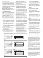
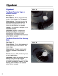
P/N 8-078-927-28
effective 03/25/2005
ELECTRIC MOTORS
GEARMOTORS AND DRIVES
Installation and Service Instructions for
180-210 C-Face Motors
For replacement parts refer to
sheet part number 8-078-917-77.
Instructions and parts list also available
at www.rexnord.com/stearns.
Drain plug
(WASHGUARD brakes only)
Figure 1 (for dimensions see page 4.)
Important
Please read these instructions carefully before
installing, operating, or servicing your brake. Failure
to comply with these instructions could cause injury
to personnel and/or damage to property if the brake
is installed or operated incorrectly. For definition of
limited warranty/ liability, contact Leeson Electric
Corporation, P.O. Box 241, 2100 Washington
Street, Grafton, WI, 53024-0241, (262) 377-8810.
Caution
3. To prevent an electrical hazard, disconnect
power source before working on the brake. If
power disconnect point is out of sight, lock disconnect in the off position and tag to prevent
accidental application of power.
4. Make certain power source conforms to the
requirements specified on the brake nameplate.
5. Be careful when touching the exterior of an operating brake. Allow sufficient time for brake to cool
before disassembly. Surfaces may be hot
enough to be painful or cause injury.
1. Installation and servicing must be made in compliance with all local safety codes including
Occupational Safety and Health Act (OSHA). All
wiring and electrical connections must comply
with the National Electric Code (NEC) and local
electric codes in effect.
6. Do not operate brake with housing removed. All
moving parts should be guarded.
2. Do not install the brake in atmospheres containing explosive gases or dusts.
8. For proper performance and operation, only genuine Stearns parts should be used for repairs
and replacements.
7. Installation and servicing should be performed
only by qualified personnel familiar with the construction and operation of the brake.
9. After usage, the brake interior will contain burnt
and degraded friction material dust. This dust
must be removed before servicing or adjusting
the brake.
DO NOT BLOW OFF DUST using an air hose. It
is important to avoid dispersing dust into the air
or inhaling it, as this may be dangerous to your
health.
a) Wear a filtered mask or a respirator while
removing dust from the inside of a brake.
b) Use a vacuum cleaner or a soft brush to
remove dust from the brake. When brushing,
avoid causing the dust to become airborne.
Collect the dust in a container, such as a bag,
which can be sealed off.
10. The motor should not be run with the brake in
the manual release position to avoid overheating of friction disc(s).
Figure 2
LEESON ELECTRIC
P.O. BOX 241
A Subsidiary of Regal-Beloit Corporation
2100 Washington Street
Grafton, WI 53024-0241
U.S.A
Remove screws, conical spring washers
(142W), and flat washers (142X).
General Description
The 87,700 Series coupler is a spring-set, electrically released, self adjusting brake. The double C-face allows the brake to directly couple a
C-face motor to a C-face gear reducer. Or, for
in-line application, the brake can be mounted
directly to a foot mounted
C-face motor, using the bearing mounted output
shaft as an in-line drive shaft.
Note: Coupler brake is designed for in-line
applications only. Do not apply overhung or side
load to brake output shaft.
E. Remove pressure plate (5), friction disc (4)
and stationary disc (3).
F. Attach endplate (2) to NEMA C-face of
motor using four 1/2-13 socket head cap
screws and medium spring lock washers
(not supplied) torque per manufacturer’s
specifications. (Head of cap screws must
not project above friction surface.)
Note 4: If motor, with or without reducer, is
to be ceiling mounted after assembly, entire
brake will have to be rotated 180° or upside
down so it will be positioned with solenoid
plunger (29) above frame when final assembly is mounted on ceiling. Similarly, for horizontal wall mounting, rotate 90°.
I. Installation Procedure
Note 1: Check face of motor to which brake is
to be mounted, to be sure NEMA dimensions of
0.004″ T.I.R. on concentricity and face run out
are met. Shaft run out is to be within 0.002″
T.I.R. Maximum shaft end float is 0.020″. Use
standard length NEMA shaft.
G. Reassemble friction discs (be sure
friction discs slide freely, file I.D. if necessary), springs (if vertical), stationary discs,
and pressure plate in correct sequence and
position. All parts must
slide freely. The universal mounting pressure
plate presently used has three tapered reliefs
on outboard face.
Note 2: The effectiveness of the dust-tight
waterproof brake enclosure depends on a fully
enclosed motor C-face as the brake face is not
sealed.
A. Remove hub (16) from brake assembly. With
key (not furnished) in place on motor shaft,
slide hub onto shaft to 1” (± 1/32”) of standard motor C-face. Tighten the three set
screws over the motor shaft to 290 in-lb (on
single disc brake, the set screw over the
keyway should be tightened to 87 in-lb).
Note 5: Brakes with a single friction disc do
not have stationary discs. Vertically mounted
brakes will have springs to separate stationary discs (except one disc vertical below).
Note color coded sequence of springs (figures 2A, 2B, & 2C) for proper assembly of
vertical mounting components.
Note 3: On most applications, particularly in
H. Mount support plate assembly, torque
screws to 50 in-lbs in endplate. Conical
spring washer installed under the screw
head. Flat washer used under the
conical spring washer only with
aluminum support plate. Be sure that assembly is mounted with the solenoid
in a vertical position (plunger above frame)
as shown when brake is horizontal. If
plunger is not tied down and has allowed the
mechanism to overadjust, it will have
vertical position, a set screw dimple drilled
into shaft is recommended.
B. Remove housing bolts (15), lock washers
(15W) and housing (7).
C. Depress solenoid plunger (29) and tie
plunger to frame (79).
D. Remove entire support plate assembly (142)
by evenly unscrewing screws (142S).
1
1
3
Description
Blue Vertical Push-in Spring
Figure 2A
2 Friction Discs - Vertical Above
Item No.
No. Req.
1
2
1
3
Plain Vertical Push-in Spring
2
3
Red Vertical Push-in Spring
2
J. See Section on Electrical Connection of
Brake.
K. Assemble housing and shaft assembly, rotating shaft (35) to engage key (35K) into hub
keyway. Be sure housing is assembled with
manual release on right hand (solenoid) side
(looking at output shaft side) or release lever
(148) will not latch. Replace housing bolts
and tighten evenly to 118 lb-ft of torque.
L. Remove access plug (7P). Insert a 3/16″
hex wrench and tighten the two set screws
to 290 in-lb. (set screws are located 120°
either side of the keyway).
M. For reducer application, mount and secure
brake/motor combination to mounting face of
reducer.
For alignment when brake shaft is direct-connected to another shaft by a coupling refer to
coupling manufacturer′s suggested procedure. Side or overhung load is not permitted.
Consult factory for reversing applications.
CAUTION 1: Inverter Motor and Special
Control Systems. This brake contains a single
phase AC coil that requires instantaneous
power within ± 10% of rating at the coil. A separate power source is required when this brake
is used in conjunction with a motor or control
system that limits voltage or current input (i.e.
inverter motors) or causes a ramping of the
power supply.
or pinched, and that leads will not be rubbed by
friction disc, trapped between solenoid plunger
and frame, caught between lever arm and endplate, or by linkage.
Note 2: See figure 3 for dual voltage coil connection and connect to any two leads of single
or three-phase motor of the same voltage. The
brake can also be wired to external switch contacts providing proper voltage other than that
used to control the motor. Normally, the motor
and brake contacts are interlocked.
Endplate
2 Friction Discs - Vertical Below
Item No.
No. Req.
Repeat this process several times to set air
gap on solenoid. (Check Self-Adjust
Maintenance Section for proper gap measurement, or corrective action for improper
gap.)
Note 1: Be sure lead wires to coil are not tight
Description
Figure 2B
1
I. Remove plunger tie-down. Manually
lift solenoid plunger to maximum travel
and release. Complete electrical connections, (See Section on Electrical
Connection of Brake.) Depress solenoid
plunger manually or electrically, and allow
it to snap up.
II. Electrical Connection of Brake
1 Friction Disc - Vertical Above
Item No.
No. Req.
to be reset before mounting support plate.
In this case the lever arm throat will
be near, or touching, the pinion teeth. Refer
to Self-Adjust Maintenance. Loosen pressure spring cap screw (19) until pressure
spring (11) is free, mount support plate
assembly to endplate, and retighten spring
cap screw until snug. Do not overtighten!
Torque to a maximum of
100 in-lbs.
Description
1
3
Blue Vertical Push-in Spring
2
3
Red Vertical Push-in Spring
Figure 2C
2
Note 3: To use a 230 volt coil (or a 230/460
dual voltage coil connected for 230 volts) with a
230/460 dual voltage three-phase motor, the
brake leads are connected across two motor
terminals as shown, or other equivalent combinations. If a 230 volt brake coil is
slightly, or decreased by lowering slightly,
wrap spring stop (76). Be sure to retighten
(stop) screws (76S). Manually lift plunger to
maximum travel and release. Depress
plunger, manually or electrically, and allow it
to snap up. Repeat several times, then
recheck air gap for factory setting of 13/16″
to 15/16″.
AC Voltage Coil Connection
Class B Coil (black)
Note: To measure solenoid air gap on verti-
For
Power Line A Power Line B Tie Leads
Low voltage
1 and 3
2 and 4
–
High voltage
1
2
3 and 4
Figure 3
Figure 4
Figure 5
connected as shown in figures 4 and 5 the
motor can be operated on either 230 volts or
460 volts with no effect on brake operation.
III. General Maintenance
Warning! Any mechanism or load held in position by the brake should be secured to prevent
possible injury to personnel or damage to
equipment before any disassembly of the
brake is attempted or the manual release lever
is operated on the brake. Observe all cautions
listed at the beginning of this manual.
Note 1: Replacement part kits for many items
are available and contain retrofit instructions.
Note 2: Do not lubricate any part of the brake
as this may cause a malfunction and/or loss of
torque.
A. Coil replacement
All standard NEMA AC voltage coils are available in kits. Select coil kit from appropriate
replacement parts list for the particular brake
series being serviced.
B. Friction disc replacement
Note: Replace friction discs in single disc
brakes when wear surface area is one half the
original disc thickness (1/4″). In multiple disc
brakes, replace all friction discs when throat of
lever arm is within 1/16″ of touching teeth of
pinion.
C. Self-adjust maintenance
Since the self-adjust brake automatically
adjusts itself for friction disc wear, maintenance
is held to a minimum. The solenoid is factory
set with a 13/16″ to 15/16″ air gap, and
requires no resetting, even when changing friction discs. The gap is determined by the position of wrap spring stop (76). Should air gap
change, follow the steps listed below:
1. If (stop) screws (76S) had been loosened
and retightened, the air gap may require
resetting. The gap is measured between
mating surfaces of plunger (29) and solenoid
frame (79), and may be increased by raising
cally mounted brakes, grasp solenoid link to
hold plunger in a free horizontal position and
move toward solenoid frame until spring
pressure is felt. Holding firmly in this position
measure air gap between mating (ground)
surface on solenoid frame and solenoid
plunger. Adjust to proper gap as directed in
Self-Adjust Maintenance. Check gap by
again holding plunger as directed.
2. Tang of wrap spring must be below, and
must make contact with, wrap spring stop
(76) when
solenoid lever
Air
(28) is manual- gap
ly raised. If
stop is bent
outward, allowing tang to
bypass it,
rebend to
square posiFigure 6
tion, assemble
correctly, and reset solenoid air gap as
described in Paragraph 1.
3. Should air gap have decreased or disappeared, the solenoid lever and pinion
assembly (8) may have
become contaminated
due to lubrication or
residue as a result of
overheating of brake.
For reference purposes
refer to Figure 7. Tang A
should align with the
centerline of hole B.
Use kit #5-66-7371-00 if
replacement is necesFigure 7
sary.
4. Check condition and positioning of
pinion and rack assembly. Replace parts as
necessary with complete assemblies.
D. Solenoid lever and pinion assembly
replacement
If pinion teeth are worn, replace entire assembly. Consult appropriate parts list for kit number. Check sector gear of lever arm for wear.
If sector gear teeth of lever arm are worn,
replace entire lever arm assembly available as
a kit from appropriate repair parts list. Also
check pinion teeth for wear.
E. Drain plug removal (WASHGUARD
brakes only)
If moisture has accumulated inside the brake
enclosure, remove the drain plug (location
shown in Figure 1). Replace plug after fluid has
drained.
IV. Troubleshooting
A. If brake does not stop properly or
overheats, check the following:
1. Is manual release engaged, and is motor
energized?
3
2. Friction discs may be excessively worn,
charred or broken.
3. Hub may have become loose and shifted
on shaft.
4. Is hub clean and do friction discs slide
freely?
5. Are controls which govern start of brake
cycles operating properly?
6. Are limit switches, electric eyes, etc. functioning properly?
7. On vertically mounted brakes, are
springs in place in disc pack?
See P/N 8-078-937-06.
8. Have mounting faces loosened?
9. Pressure spring may be improperly assembled or broken.
10. Is solenoid air gap adjusted correctly?
(See Self-Adjust Maintenance,
Section III, Item D.)
11. Check linkage for binding. The approximate
pressure applied to the top of the solenoid
link to move plunger is:
#5 coil
3 lbs
#6 coil (15 lb-ft)
#6 coil (25 lb-ft)
#8 coil
5-1/2 lbs
9 lbs
16 lbs
If excessive force is required, determine
cause of binding and correct. Do not overlook bent, worn or broken plunger guides
as a possible cause for binding.
12. Solenoid lever stop (22) must be in place
on support plate.
13. Solenoid may not be energizing and releasing the brake. Check voltage at the coil and
compare to the coil and/or nameplate voltage rating.
14. A voltage drop may be occurring. If excessive drop in voltage is noted, check wire
size of power source. Correct as needed.
Note: A method to check voltage at coil is
to insert a block of wood of the approximate thickness of the solenoid air gap
between the solenoid frame and plunger.
(The block will prevent brake from releasing when coil is energized.) Connect voltmeter leads at the coil terminals or lead
wires. Energize coil. Voltmeter needle will
not fluctuate and reading can be taken.
Reading should be taken immediately and
the coil de-energized to prevent over-heating of the coil. Compare voltage reading
with coil rating.
15. Check slots of endplate for wear at the
areas where stationary discs are in contact.
Grooves in the slots can cause hang-up or
even breakage of ears of stationary discs.
If grooving is noted, replace endplate.
16. Check that heads of mounting bolts do not
extend above wear surface of endplate.
17. Check pressure spring length to insure correct compressed height. Approximate original spring lengths are given in the following
table so that correct setting may be verified
and corrected if necessary. With worn friction discs, add amount of wear to the
approximate spring length shown in table.
18. If a heater is supplied and excess rusting
has occurred in brake, check power source
to heater to be sure it is operating and that
heater is not burned out.
19. If stopping time is more than two seconds
(rule of thumb) and/or the application is
Color
Torque
(lb-ft)
Compressed
Spring Length
White
15
3-1/4”
Orange
25 & 50
3-1/4”
Purple
35
3-1/4”
20. Use Loctite ® 242 to secure link screw nut
to link screw if vibration causes nut to
loosen.
B. If brake hums, solenoid pulls in slowly, or coil burns out, check the following:
1. Voltage supply at coil versus coil rating.
1. Check mounting face run out, mounting rabbet eccentricity and shaft run out. See
Installation Procedure, Section I, Note 1.
Correct as required.
2. Check for signs of the outside diameter of
the friction disc(s) rubbing on the inside
3.12 2.62
3.12
2.62
A
H
0.19 0.19
0.19
A
G
0.44
2.12
A
E
2.12 2.12
C
2.62
A
2.81
2
4X
180
2
4X
2
4X
2
4X
Dimensions (Inches)
2.81 2.81
Brake
Bore & NEMA
Shaft Frame
Dia.
Size
(U/X)
3.31
NEMA
Enclosure
8.38
175590.00 1087752B31QG
C. If brake is noisy during stopping:
210
175588.00 1087742B31QG
175589.00 1087751031QG
9. Excessive voltage drop when motor starts.
Check size of lead wires for motor starting
current and solenoid inrush current. See
Section IV-A, Item 11, 12, 14 and 15.
1-1/8”
1087722B11QG
1087731011QG
1087732B11QG
1087741031QG
8. Sector gear and pinion teeth may be jamming due to excessive tooth wear.
1-3/8”
175584.00
175585.00
175586.00
175587.00
6. Is solenoid dirty?
8.38 8.38
175583.00 1087721011QG
5. Solenoid frame and plunger may be excessively worn.
8.88
Brake
Coil
Rating
(VAC)
230/460
PART NUMBERS
2. Is solenoid air gap excessive?
(See Self-Adjust Maintenance.)
Stearns Part
Number
4. Plunger guides may be excessively worn.
Does solenoid plunger rub on solenoid
frame laminations? If so, replace plunger
guides.
7. Solenoid mounting screws may have
become loose, causing frame to shift and
plunger to seat improperly.
more than five stops per minute, check
thermal requirements of load versus thermal rating of brake.
Leeson
Part Number
3. Shading coils may be broken.
4
diameter of the endplate. This would indicate
brake is eccentric with respect to the motor
shaft and/or the shaft is deflecting during a
stop. Check alignment and shaft diameter.
Also check for worn motor bearings. If
realignment does not correct the problem, a
larger diameter shaft may be required. Shaft
deflection may also be caused by excessive
overhang of brake from motor bearing.
Additional shaft support may be required.
3. Check for bad motor bearings. Replace
if necessary. Check for excessive shaft endfloat. Correct as required.