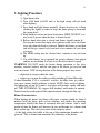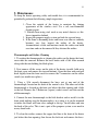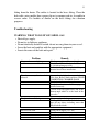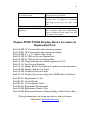
1
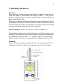
Direct Draft Propane Heater
Operating and Installation
Instruction Manual
*KEEP THIS MANUAL FOR FUTURE REFERENCE*
P9000 & P12000 Model Heaters
** Please read from beginning to end before installing and operating.
Heater’s Serial #:
Quality Controlled by- Doug & Don
Form#7.2-247 Issue#1 Apr. 8 2011
2
Table of Contents
Table of Contents & Packing List… Pg. 2
Warnings… Pg. 3
1. About a Direct Draft Propane Heater… Pg. 4
2. Important Notes... Pg. 4
3. Installing your Heater… Pg. 5
- Location… Pg. 5
- Safety Clearances… Pg. 5
- Mounting… Pg. 5
- Chimney Pipe… Pg. 6
- Deckcap Deck Fitting… Pg. 7
- Deckcap Deck Fitting Diagram… Pg. 7
4. Connecting the Propane Fuel … Pg. 8
- Propane locker diagram… Pg. 9
- Fuel Connection Options… Pg. 9
- Electrical 12v Fan… Pg. 10
5. Lighting Procedure … Pg. 11
- Flame Characteristics… Pg. 11
6. Maintenance… Pg. 12
- Thermocouple & Orifice Cleaning… Pg. 12
- Troubleshooting … Pg. 13
- Replacement Parts… Pg. 14
7. Warranty Policy… Pg. 15
8. Registering your Warranty… Pg. 18
Packing List
1.
2.
3.
4.
P9000/ P12000 Heater Fireplace
2.5” x 28” Double-walled Stainless Exhaust Pipe
2.5” Stainless Deckcap Fitting, Gasket & Dress Ring
Stainless wall mounting backing plate
3
WARNINGS
- This is a low pressure appliance and MUST have a separate low pressure
regulator installed or operation can result in a dangerous fire or extreme
internal damage to your heater.
- Improper use of a gas appliance can result in serious injury, fire, explosion,
carbon monoxide poisoning, oxygen depletion or even death.
- Do not operate this heater unattended.
- Turn off the heater when refueling.
- This propane heater requires an installed chimney for correct operation. Do
not attempt to operate the heater without the supplied flue chimney installed
correctly as required in this manual.
- Do not store or use gasoline or other flammable vapors or liquids in the
vicinity of this appliance.
- Do not install this appliance in spaces containing internal combustion
engines, fuel tanks, or joints and fittings of their fuel systems.
- All installations must conform with local codes or in the absence of any
codes with the current National Fuel Gas Code, ANSI Z223.1 or current
CAN/CGA B149, Installation Codes.
- Manufactured or mobile home installation must conform to Manufactured
Home Construction and Safety Standard, Title 24 CFR, Part 3280, or, when
not applicable, the Standard for Fire Safety Criteria for Manufactured Home
Installation Sites and Communities, ANSI/NFPA 501A,(USA) or Mobile
Homes Standard, CAN/CSA-Z240 MH Series, in Canada.
- Follow ALL installation and operation procedures.
4
1. About a Direct Draft Propane Heater
This direct vent propane heater fireplace is a clean burning low pressure
propane appliance for use on board small marine vessels and many other
different applications.
These heaters are equipped with a stainless double walled vent pipe and
deckfitting/ exhaust cap. Fresh air is pulled from outside, through the outer
pipe into the combustion chamber while exhaust gas leaves the vessel
through the inner pipe. The air from inside the cabin is not being used for
combustion so a fresh air vent is not needed. Since, this unit has an isolated
combustion, the exhaust gases are being taken out via the chimney so no
moisture is being created.
These heaters are equipped with a CGA/AGA approved safety gas valves. If
the flame should ever be extinguished the gas will be shut-off automatically.
Manual ignition involves lighting the heater with a long barbeque lighter
with the door open and therefore avoids any initial build up of unburned gas.
The installation of a gas detector is recommended for all LPG appliances.
*NOTE: When using the P12000 heater on high setting, the fan may have to
be used to draw out the heat from the chimney pipe to keep it from sooting
the window.
2. Important Notes
Here are some important notes to remember when installing a Dickinson
direct draft propane heater:
• Mounting & location, 12v power hook-up, minimum 20” and a
maximum 56” of chimney, the location of hole for the chimney & the
fuel supply.
• The fittings needed to connect to your fuel supply.
• Install of a separate low pressure regulator (11” WC).
5
3. Installing your Heater
Location
When installing your new propane heater, keep in mind the location of the
heater and where it will maximize the heating capability.
This propane
heater is equipped with a 12v fan that will blow hot air from the top of the
heater down onto the floor.
This increases heating efficiency and provides good circulation of hot air.
Mounting the heater lower will allow for more efficient circulation of heat in
the cabin. Plan your heaters location prior to installing to ensure the location
chosen will fit the specifications and safety clearances.
Safety Clearances: Above- 20”, Front- 18”, Sides- 2”, Below- 2”
Combustible material such as the deck/ceiling or walls that are closer to the
heater then the specified safety clearances must be insulated with insulation
or millboard with a metal liner, a .5” standoff is best for air movement
behind. Another alternative is using insulation or millboard and ceramic tile.
Mounting
Secure the heater mounting plate directly onto the mounting surface. No
additional insulation is required. Use appropriate fasteners for mounting.
6
Chimney Pipe
The stainless double walled flue pipe that is included with the heater is 28”
(71cm) long. Four springs are between the inside and outside pipe to ensure
that an even air space is provided. It is important that two springs be located
at any bend in order to prevent the pipes from touching.
Extensions are available in 10” (25.4cm) part# 19-005 and 28” (71cm) part#
19-000. The maximum total length of the flue exhaust pipe can be 56” only.
Locate your heater so the distance between the heater and the pipe conform
to the available pipe lengths.
We do not recommend you cut the pipe but the pipe can be cut with a fine
hacksaw blade to the required length. To do so, twist the pipe to tighten the
pipes flexibility, then tape the end of the pipe and install a hose clamp on the
side of the pipe that you are keeping. This is so the clamp is left on the pipe
and only removed after or during installing. Cut with fine tooth hack saw
blade then use a round file to remove the large burrs in the inside of the pipe.
Use caution as the flexible pipe can be easily damaged.
Locate and run the vent pipe such that no low points occur where water or
debris can accumulate and thus block the exhaust or intake. The direct vent
chimney is flexible and can be bent to provide any angle of offset. The
chimney pipe can also exit horizontally.
If you want a horizontal exit with the chimney pipe, the heater will work
satisfactory if the full length of the pipe supplied (28” / 71 cm) is used to
achieve the 90 degree angle. When making a bend in the chimney pipe,
make the bend gradual so you don’t have hot spots in the pipe when
operating. When bending the pipe, don’t have the bend go downwards as
this will affect the draft. See diagram below. Use caution with bending the
pipe to not collapse or damage it. If the pipe needs to be cut, use extra
caution so the pipe doesn’t unravel.
7
Deckfitting and Exhaust Cap
Step - 1 Measure, cut or drill a 3" hole through the deck, ceiling or
wall where the exhaust cap will be located.
Step - 2 Make sure the sealing gasket is installed under the above
deck-flange before screwing down the fitting. Rotate the
pipe so that it is not visible. Holding the deck flange firmly
in position and secure with the 6 stainless screws supplied.
Step - 3 Attach the dress ring on the inside, underneath the fitting
with the 4 stainless screws supplied. (Make sure that the
opening lines up with the underside of the deckfiting or the
pipe will not fit correctly).
Step - 4 Install the flexible pipe on the heater. It is very important
that the small pipe fit tightly against the flue collar on the
heater (even adding some muffler tape or tin foil to fill in
any gaps of the pipe to ensure an airtight connection, the cap
and any other connections are not as important.
Step - 5 Make whatever bends are necessary in the flexible pipe and
push into the deckfitting.
Step - 6 Attach the back mounting plate and secure the heater in
position.
WARNING: Do not install the external flue cap within 20 inches (500mm)
of a refueling fitting or fuel tank vent.
NOTE: If the cap is positioned close to an edge where it can get an upward
wind then it may give some turbulence to the air intake. If this position is in
the best spot then consider the cap guard part# 19-080 that has a shield to
block the upward winds.
8
4. Connecting the Propane Fuel
This is a low pressure propane appliance. Do not use high pressure propane.
The heater only operates on low pressure propane (11’ WC or 27.4 mbars)
and should have a low pressure regulator (part# 19-151) installed within the
fuel line. The propane gas connection can either come from an already
installed propane system, a single 10 or 20 lbs tank or a 1 lb disposable
bottle. The propane tank should always face upwards. To run the fuel to the
unit, copper tubing or a rubber approved hose can be used. The size of the
fuel line should be no smaller then 3/8” in diameter. When running the fuel
line, make sure the ends are sealed so no debris can get inside the line. This
can block the gas coming through the heater small orifice. Make sure to
blow through the fuel line before connecting.
NOTE: Each low pressure propane appliance should have its own low
pressure regulator and fuel supply line as shown on the propane locker
diagram on pg. 9.
Reasons for having a separate low pressure regulator for each appliance:
1. The ABYC Standards state- 1.7.2 – Each appliance shall be served by a
separate low pressure regulator and supply line that shall originate inside the
cylinder locker. We recommend you follow the ABYC standard.
2. The regulator only serves a very low pressure of gas, through a small 3/8”
gas line, and depending on the distance, 1 regulator for 2 appliances
may starve the burners of gas for 1 appliance.
3. Some older appliances do not have thermocouples on the burners, and if the
gas valve on that appliance was left in the “on” position, gas would leak while
using the heater or any other appliance and could result in a serious explosion.
The diagram on pg. 9 is to illustrate a typical installation only and should not
be used to illustrate any particular regulatory code, insurance requirement or
to override manufacturer’s instructions on any fittings or components.
Install your propane system in accordance to local, national or industry
specific regulations. Retain the installation and owner’s manual for your gas
components such as the solenoid and regulator. Installation requirements for
9
some of these components vary by manufacturer. Install components as
directed by manufacturer’s instructions.
Existing System:
Part# 19-151: Low Pressure Regulator
Part# 19-100-10: 10ft Low Pressure Hose/ Part# 19-100-20: 20ft Hose
Part# 49-6C: 3/8” NPT X 3/8” flare fitting (hose to regulator connection)
(*see diagram on pg. 8 for other items you may need for install)
Single 10 or 20 lb Tank:
Part# 19-151: Low Pressure Regulator
Part# 19-100-10: 10ft Low Pressure Hose/ Part# 19-100-20: 20ft Hose
Part# 19-152: Fittings kit (hose to regulator & regulator to tank connections)
Disposable 1 lb Bottle:
Part# 19-150: Disposable bottle kit (includes regulator #19-151)
Part# 19-100-10: 10ft Low Pressure Hose/ Part# 19-100-20: 20ft Hose
WARNING:
- Never connect this heater directly to the propane/LPG supply. This
heater requires an external regulator that is not supplied.
10
- After the gas connection is hooked-up, test all gas lines and
connections for leaks with a soap solution. Test all lines and fittings
before the heater is lit for the first time.
Propane Locker Caution Plate Installation
Install your propane locker CAUTION plate on or inside your propane
locker for important safety reminders.
Electrical 12v Fan
The fan inside the heater is 12V DC .17 amps and the power supply must be
brought to the wire connectors of the fans ON/OFF switch through the
grommet installed at the bottom of the heater. The fan installed in this
heater is CE approved and EM compliant for FCC and CSA regulations. The
fan must have an inline fuse rated at 2 amps.
If applicable, this appliance must be electrically grounded in accordance
with local codes or in absence of local codes, with the National Electrical
Code, ANSI/NFPA 70, or the Canadian Electrical Code, CSA C22.21.
NOTE: Since this fan has such low amperage, when turning on, turn to the
high setting first to get the fan blades moving, then turn it down to low if
desired.
11
5. Lighting Procedure
1) Open heater door
2) Turn GAS knob to LOW only as the high setting will not work
when lighting.
3) Press knob and light burner manually (It may be necessary to keep
clicking the lighter in order to keep the flame going to overcome
the strong draft).
4) Keep knob pressed in and close heater door VERY SLOWLY as it
may want to go out when the door is almost closed.
5) Release knob after door is closed and flames should remain lit.
Leaving the heater door open after ignition could cause the flame
to go out when the knob is released. Should the flames go out then
turn off the gas control valve and wait a few minutes to cool, then
start over.
6) The HIGH setting may be selected after a minute or two of warm
up.
7) Use of the blower fan is optional but greatly enhances heat output
and hot air circulation. It is best to use the fan at about ½ speed.
WARNING: DO NOT touch the heater during operation as the glass
window, external surfaces and the vent pipe of the heater get very hot and
can cause burns. NOT closing the door of the heater properly may cause:
• depletion of oxygen within the cabin
• exhaust gas to enter the cabin, possibly including Carbon Monoxide.
Carbon Monoxide (CO) is a colorless, tasteless, invisible toxic gas, which
can cause serious health problems or death. NOTE: Only on first lighting,
the lubricating oil on the stainless steel pipe will produce smoke and burn
off. THIS IS NORMAL. We suggest that windows and hatches be opened.
Smoke from the inside pipe will be emitted outside, through the flue cap.
Flame Characteristics
When lighting the heater, the flames will create a roaring sound for about 5
minutes until the direct draft system stabilizes and reaches the operating
temperature. Initially the flame is extremely blue and vibrant. After a short
period of time the flames will increase in size and become less vibrant with
more yellow tips. This will create more of the fireplace effect.
At the high setting the baffle at the top of the combustion chamber will
glow red. This is normal and maximizes the efficiency of the heater.
12
5. Maintenance
To keep the heater operating safely and trouble free, it is recommended to
periodically perform the following simple inspections:
1. Clean the outside of the heater to maintain the shining
appearance of the stainless steel. Use a soft, non-flammable
cleaning agent.
2. Refrain from using steel wool or any metal abrasive as this
leaves impurities behind.
3. Inspect the propane supply system and tank for age and wear.
4. If the flame is becoming lower and lower over time or suddenly
becomes very low, inspect the orifice of the heater.
Accumulations of dirt and moisture inside the orifice can build
over time and can be removed if they obstruct the orifice.
Thermocouple and Orifice Cleaning
1. To replace the thermocouple or cleaning the orifice on the heater the front
cover must be removed. Remove the brass knobs with a 5/64 Allen wrench
along with the nuts holding the black plates.
2. Next remove all the screws on the sides of the heater (careful- hold on to
the front cover and remove the top and bottom). Open the door wide and pull
back slightly from the front cover to remove the 2 connectors on the rocker
switch (use needle nose pliers).
3. Using a 5/16 wrench disconnect the brass nut at one end of the
thermocouple, located on the back of the control valve. The other end of the
thermocouple is located on the front just below the door opening and a little
to the left. Remove the 2 Robertson (square) socket screws and take out the
old thermocouple.
4. Connect the new thermocouple to the little bracket and re install it to the
front panel making sure the thermocouple is in as deep as it can be mounted
to insure the flame will burn close enough to the tip. Install other end into
the back of the valve. This is not a part of the propane system so no need to
worry about leaks.
5. To clean the orifice, remove the copper fuel line at the front of the heater
just below the door opening, then loosen the lock nut and remove the brass
13
fitting from the heater. The orifice is located in the brass fitting. Clean the
hole with a wire smaller than a paper clip or try compressed air. Assemble in
reverse order. Use locktite or similar on the brass fittings for vibration
purposes.
Troubleshooting
WARNING: WHAT TO DO IF YOU SMELL GAS
• Shut off gas supply.
• Do not try to light any appliance.
• Do not touch any electrical switch; do not use any phone in your vessel.
• Leave the boat and ventilate with the appropriate equipment.
• Locate the cause of the leak and repair.
Problem
Remedy
No gas to burner on lighting
Check gas supply, regulator, solenoid
Check that knob is exactly on LOW which
is 9 o'clock when pressed in.
Orifice is clogged due to dirt build up or
material in new hose installation.
Fire does not stay lit when knob
released
Depress knob, light burner and almost
close door. Release knob and then CLOSE
COMBUSTION CHAMBER DOOR
Check that the door seal is good
Check that the internal exhaust pipe is
installed correctly
Loosen, clean and tighten brass nut at the
thermocouple which is at the back of the
gas valve.
Fireplace shuts off during use
No gas supply – check gas pressure
Blockage of the air intake – check the vent
pipe for any object, including water that
may block the intake.
Fan does not work
Check power supply (12 V DC)
Check connection of wires
Check proper functioning of switch
Replace fan
14
Gas odor even when control knob
is in OFF position
1. Gas leak. See Warning.
Locate and correct all leaks
2. Check and, if required, replace the
control valve. If operation is attempted
with high pressure gas, the valve could
fail.
Slight smoke or odor during initial This is a normal event, caused by burning
operation
off of residues from the manufacturing
process. Smoke and odor should stop after
a few hours of operation
Propane P9000/ P12000 Fireplace Heater Accessories &
Replacement Parts
Part# 19-000: 28” Extension Kit with connecting coupling
Part# 19-005: 10” Extension Kit with connecting coupling
Part# 19-030: 2.5” x 18” Stainless Flue Guard
Part# 19-100-10: 10ft Low Pressure Propane Hose
Part# 19-100-20: 20ft Low Pressure Propane Hose
Part# 19-150: Disposable bottle kit (includes regulator #19-151)
Part# 19-151: Low Pressure Regulator
Part# 19-152: Fittings Kit (hose to regulator & regulator to tank connections)
Part# 19-080: Stainless Exhaust Cap Guard
Part# 19-200: Weather Guard to use alone
Part# 19-210: Weather Guard to use with part# 19-080 Exhaust Cap Guard
Part# 01-031: Replacement 12v Fan
Part# 01-073: On/ Off Switch
Part# 01-074: 12v Fan Speed Control
Part# 02-014: Replacement Thermocouple
Part# 19-020: Replacement Control Valve
Part# 19-050: Replacement Stainless Deckcap Fitting, Gasket & Dress Ring
*For replacement parts not shown here please e-mail us for more
information. [email protected]
15
6. Warranty Policy
We at Dickinson & Sig Marine wish to maintain a reasonable and easy
system for returns, warranty, returns and exchanges. To accomplish this, we
would like to inform you of some helpful guidelines and procedures to use
and follow when sending back product to the Dickinson Marine. All
correspondence regarding returns, warranties and exchanges will go through
the factory of Dickinson Marine in Coquitlam, BC, Canada and the product
MUST be returned to this location.
Warranty
Dickinson Marine warranties all of its products for a period of one year
dated from the purchase of the product by the end user with proof of
purchase or a registered warranty. The warranty card should be copied for
your records and returned to Dickinson to activate your warranty within 90
days of your purchase. You can also activate it online at
www.dickinsonmarine.com
A copy of the warranty card must have been received or a proof of purchase
must be presented to receive the warranty.
1. The customer can contact us directly to settle any warranty issues. We
are pleased to help. Call us toll free 1-800-659-9768 or email:
[email protected]
2. If the customer is returning a complete product they see as defective,
be sure the product has been assembled correctly and is being used
correctly. If you are not sure please call our Technical Help
Department @ 1-800-659-9768. Dickinson Marine will not provide
credit for used products that are not defective. In these cases, it is best
to call the factory to determine if the product is being used correctly,
has been assembled correctly or is in fact defective.
3. All products being sent back to Dickinson Marine must have a Return
Authorization Number. Contact us at Dickinson Marine toll free 1800-659-9768 or e-mail [email protected] to obtain a
Return Authorization Number. This allows us to track and process
your return. Once you have received an RA# from us, include your
proof of purchase and ship to the address below. We recommend you
16
ship using the mail service insured and retain a tracking number.
Customers are responsible for the shipping costs for all returns and
exchanges.
Sig Marine Returns
Unit# 101-17728 66 Ave
Surrey, BC
V3S 7X1 Canada
4. Products that are demonstrably older than the warranty period or those
that have obviously been misused will not be returned, exchanged, or
repaired.
Non-defective Returns & Exchanges
Dickinson reserves the right to apply a 20% restocking fee for returned
product sent back. An RA # will be needed from the factory to facilitate any
return. Credits will be made at the last purchased price for that part number.
Limited Warranty
WARRANTY PROVISIONS: Dickinson warrants this product to be free of defects in
workmanship and materials for a period of one year. This warranty is limited to claims
submitted in writing within a one-year period following the date of purchase. If any part
of your new product fails because of a manufacturing defect within the warranty period
Dickinson offers to replace said parts free of charge, provided, however, that such parts
have not been improperly repaired, altered or tampered with or subjected to misuse,
abuse or exposed to corrosive conditions. This warranty, however, is limited by certain
exclusions, time limits and exceptions as listed below. Read these limitations and
exclusions carefully.
TIME LIMIT: This warranty is given too and covers only the original purchaser.
Coverage terminates one year from the date of purchase for parts replacement.
EXCLUSIONS : This warranty does not cover or include : (a) Any normal deterioration
of the product and appearance of items, due to wear and/or exposure; (b) any guarantees,
promises, representations, warranties or service agreements given or made by an
authorized distributor or other person selling this product, other than those specifically
stated herein; (c) any damage or defect due to accident, improper repair, alteration,
unreasonable use including failure to provide reasonable and necessary maintenance,
misuse or abuse of the equipment, or exposure to corrosive conditions. This warranty is
conditioned upon normal use, reasonable and necessary maintenance and service of your
product, and written notice being given promptly upon Buyer's discovery of a warranty
claim, pursuant to paragraph 6 below.
Reasonable and necessary maintenance is
17
maintenance which you are expected to do yourself or have done for you. It is
maintenance, which is necessary to keep your product performing its intended function
and operating at a reasonable level of performance.
DAMAGE LIMITATION WARNING : IN NO EVENT SHALL Dickinson BE LIABLE
FOR ANY INCIDENTAL OR CONSEQUENTIAL DAMAGES, INCLUDING (BUT
NOT LIMITED TO) LOSS OF USE OF THE PRODUCT, LOSS OF TIME,
INCONVENIENCE, EXPENSES FOR TRAVEL, LODGING TRANSPORTATION
CHARGES, LOSS BY DAMAGE TO PERSONAL PROPERTY OR LOSS OF
INCOME, PROFITS OR REVENUE.
ORAL OR IMPLIED WARRANTY LIMITATIONS: The foregoing warranty is
exclusive and in lieu of all other warranties, written or oral, expressed or implied,
including but not limited to any warranty or merchantability or fitness for a particular
purpose.
TRANSFER LIMITATIONS: This warranty is not assignable or transferable. It covers
only the original purchaser.
CLAIM PROCEDURE: In the event of a defect, problem or that a breach of this
warranty is discovered, in order to protect any warranty rights you must promptly notify
Dickinson. Give name, address, and model name, location of unit, description of
problem and where you can be reached during business hours.
RESERVED RIGHT TO CHANGE: Dickinson reserves the right to make changes or
improvements to products it produces in the future without imposing on itself any
obligations to install the same improvements in the products it has previously
manufactured.
SECOND OR SUBSEQUENT OWNER: Dickinson does not give any warranty to
secondary or subsequent purchasers, and it disclaims all implied warranties to such
owners.
INSPECTION: To assist you in avoiding problems with your product and to validate this
warranty you are required to do the following: (a) read the warranty; (b) inspect the
product. Do not accept delivery until you have examined the product with your supplier;
(c) ask questions about anything you do not understand concerning the product.
OWNER REGISTRATION: Fill out the WARRANTY CARD within 90 days from the
date of delivery. WARRANTY: RETURN OF THE CARD IS CONDITION
PRECEDENT TO WARRANTY COVERAGE AND PERFORMANCE. IF YOU DO
NOT FILL OUT AND MAIL THE CARD AS DIRECTED, YOU WILL NOT HAVE A
WARRANTY.
18
7. Register your Warranty…..
Please register your warranty with Sig Marine. Fill out and send back the
warranty registration below. Make sure to include the serial # for our
records.
No warranty will be extended for improper installations. Use of any
unapproved materials, equipment, or installation procedures will result in a
voided warranty. Do not use any substitutes of the heaters valve, burner or
fan other then the ones supplied by Dickinson. Dickinson Marine accepts
no liability for any damage or loss of service resulting from unapproved
modifications.
Warranty Form
I have read and understand the Limited Warranty and the entire Instruction
Manual and agree to the terms and conditions. (PLEASE PRINT)
Name:
Address:
Phone:
Heater Model Name:
Heater Serial #:
Date of Purchase:
Seller’s Name:
Seller’s Location:
Signature:
This warranty form can also be filled out online. www.sigmarine.com
19
Sig Marine Products
#101-17728 66 Avenue, Surrey, BC
V3S 7X1 Canada
Tel: 604-574-8641
Fax: 604-574-8659
E-mail: [email protected]
Website: www.sigmarine.com
All rights reserved. No part of this manual may be reproduced without permission
in writing from Sig Marine. Sig Marine also reserves the right to modify or change
without notice, any materials, applications, equipment, accessories, and/or prices.
All measurements and weights are approximate.