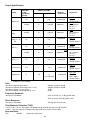
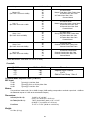
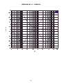
1
CPM™ 2462 Operations Manual
Operating Guide
For more information on other great Crest products, go to your local Crest dealer or online at www.crestaudio.com.
Intended to alert the user to the presence of uninsulated “dangerous voltage” within the product’s
enclosure that may be of sufficient magnitude to constitute a risk of electric shock to persons.
Intended to alert the user of the presence of important operating and maintenance (servicing)
instructions in the literature accompanying the product.
CAUTION: Risk of electrical shock — DO NOT OPEN!
CAUTION: To reduce the risk of electric shock, do not remove cover. No user serviceable parts inside. Refer
servicing to qualified service personnel.
WARNING: To prevent electrical shock or fire hazard, do not expose this appliance to rain or moisture. Before
using this appliance, read the operating guide for further warnings.
Este símbolo tiene el propósito, de alertar al usuario de la presencia de “(voltaje) peligroso” sin aislamiento dentro de la caja del producto y que puede tener una magnitud suficiente como para constituir
riesgo de descarga eléctrica.
Este símbolo tiene el propósito de alertar al usario de la presencia de instruccones importantes sobre la
operación y mantenimiento en la información que viene con el producto.
PRECAUCION: Riesgo de descarga eléctrica ¡NO ABRIR!
PRECAUCION: Para disminuír el riesgo de descarga eléctrica, no abra la cubierta. No hay piezas útiles dentro.
Deje todo mantenimiento en manos del personal técnico cualificado.
ADVERTENCIA: Para evitar descargas eléctricas o peligro de incendio, no deje expuesto a la lluvia o humedad
este aparato Antes de usar este aparato, Iea más advertencias en la guía de operación.
Ce symbole est utilisé dans ce manuel pour indiquer à l’utilisateur la présence d’une tension dangereuse
pouvant être d’amplitude suffisante pour constituer un risque de choc électrique.
Ce symbole est utilisé dans ce manuel pour indiquer à l’utilisateur qu’il ou qu’elle trouvera d’importantes
instructions concernant l’utilisation et l’entretien de l’appareil dans le paragraphe signalé.
ATTENTION: Risques de choc électrique — NE PAS OUVRIR!
ATTENTION: Afin de réduire le risque de choc électrique, ne pas enlever le couvercle. Il ne se trouve à l’intérieur
aucune pièce pouvant être reparée par l’utilisateur. Confiez I’entretien et la réparation de l’appareil à un réparateur
Peavey agréé.
AVERTISSEMENT: Afin de prévenir les risques de décharge électrique ou de feu, n’exposez pas cet appareil à la
pluie ou à l’humidité. Avant d’utiliser cet appareil, lisez attentivement les avertissements supplémentaires de ce
manuel.
Dieses Symbol soll den Anwender vor unisolierten gefährlichen Spannungen innerhalb des Gehäuses
warnen, die von Ausreichender Stärke sind, um einen elektrischen Schlag verursachen zu können.
Dieses Symbol soll den Benutzer auf wichtige Instruktionen in der Bedienungsanleitung aufmerksam
machen, die Handhabung und Wartung des Produkts betreffen.
VORSICHT: Risiko — Elektrischer Schlag! Nicht öffnen!
VORSICHT: Um das Risiko eines elektrischen Schlages zu vermeiden, nicht die Abdeckung enfernen. Es befinden
sich keine Teile darin, die vom Anwender repariert werden könnten. Reparaturen nur von qualifiziertem
Fachpersonal durchführen lassen.
ACHTUNG: Um einen elektrischen Schlag oder Feuergefahr zu vermeiden, sollte dieses Gerät nicht dem Regen
oder Feuchtigkeit ausgesetzt werden. Vor Inbetriebnahme unbedingt die Bedienungsanleitung lesen.
2
IMPORTANT SAFETY INSTRUCTIONS
WARNING: When using electrical products, basic cautions should always be followed, including the following:
1.
2.
3.
4.
5.
6.
7.
8.
9.
10.
11.
12.
13.
14.
15.
16.
17.
18.
Read these instructions.
Keep these instructions.
Heed all warnings.
Follow all instructions.
Do not use this apparatus near water.
Clean only with a dry cloth.
Do not block any of the ventilation openings. Install in accordance with manufacturer’s instructions.
Do not install near any heat sources such as radiators, heat registers, stoves or other apparatus (including amplifiers)
that produce heat.
Do not defeat the safety purpose of the polarized or grounding-type plug. A polarized plug has two blades with one
wider than the other. A grounding type plug has two blades and a third grounding plug. The wide blade or third prong is
provided for your safety. If the provided plug does not fit into your outlet, consult an electrician for replacement of the
obsolete outlet.
Protect the power cord from being walked on or pinched, particularly at plugs, convenience receptacles, and the point
they exit from the apparatus.
Note for UK only: If the colors of the wires in the mains lead of this unit do not correspond with the terminals in your
plug‚ proceed as follows:
a) The wire that is colored green and yellow must be connected to the terminal that is marked by the letter E‚ the earth
symbol‚ colored green or colored green and yellow.
b) The wire that is colored blue must be connected to the terminal that is marked with the letter N or the color black.
c) The wire that is colored brown must be connected to the terminal that is marked with the letter L or the color red.
Only use attachments/accessories provided by the manufacturer.
Use only with a cart, stand, tripod, bracket, or table specified by the manufacturer, or sold with the apparatus. When a
cart is used, use caution when moving the cart/apparatus combination to avoid injury from tip-over.
Unplug this apparatus during lightning storms or when unused for long periods of time.
Refer all servicing to qualified service personnel. Servicing is required when the apparatus has been damaged in any
way, such as power-supply cord or plug is damaged, liquid has been spilled or objects have fallen into the apparatus,
the apparatus has been exposed to rain or moisture, does not operate normally, or has been dropped.
Never break off the ground pin. Write for our free booklet “Shock Hazard and Grounding.” Connect only to a power
supply of the type marked on the unit adjacent to the power supply cord.
If this product is to be mounted in an equipment rack, rear support should be provided.
Exposure to extremely high noise levels may cause a permanent hearing loss. Individuals vary considerably in susceptibility to noise-induced hearing loss, but nearly everyone will lose some hearing if exposed to sufficiently intense noise
for a sufficient time. The U.S. Government’s Occupational Safety and Health Administration (OSHA) has specified the
following permissible noise level exposures:
Duration Per Day In Hours
8
6
4
3
2
1 1⁄2
1
1
⁄2
1
⁄4 or less
Sound Level dBA, Slow Response
90
92
95
97
100
102
105
110
115
According to OSHA, any exposure in excess of the above permissible limits could result in some hearing loss. Ear plugs or protectors to the
ear canals or over the ears must be worn when operating this amplification system in order to prevent a permanent hearing loss, if exposure
is in excess of the limits as set forth above. To ensure against potentially dangerous exposure to high sound pressure levels, it is
recommended that all persons exposed to equipment capable of producing high sound pressure levels such as this amplification system be
protected by hearing protectors while this unit is in operation.
SAVE THESE INSTRUCTIONS!
3
ENGLISH
CPM™2462
Rack-Mountable Recording and Sound Reinforcement Mixer
II. INTRODUCTION
Thank you for purchasing the Crest Performance CPM™2462. The CPM 2462 was design to not only
provide maximum versatility and performance for live sound applications, but also to excel when
used for recording. To begin, let’s identify these features.
*
*
*
*
*
*
*
*
*
*
*
*
*
*
*
*
*
*
*
*
*
*
*
*
Sixteen input channels with XLR mic inputs EQ, pan, aux and group assign controls
Eight additional stereo line inputs (17-24)
Four different types of input channel configurations for outstanding versatility
Universal chassis design allowing rackmount or desktop placement
Very-low-noise mic inputs (XLR) with gain trim on all input channels
Smooth, 60 mm fader on each channel and Groups 1-4
Phantom power with separate defeat switches for Channels 1-2 and 3-16
Channels 1-8 optimized for 8-track recording (direct output)
Insert (in/out) jacks on Channels 1-8
Six aux outputs (2 balanced XLR)
Four mono subgroups (1 through 4)
One stereo subgroup pair (5 and 6)
Phase and pad switches on (1 and 2)
Mute switch, clip LED and signal present LED on all input channels
Switchable low cut filter on Channels 3-8
Smooth, 60 mm left and right master faders
PFL on all input channels and subgroups
Stereo headphone and control room outputs
Balanced mono output (XLR) with separate level control
Balanced stereo L/R output (XLR)
Unbalanced stereo L/R output (1/4")
Left and right master inserts (1/4")
Stereo tape in (1/4" or RCA) and tape out (RCA) jacks
Stereo control room outputs (1/4")
As you can see, this mixer is packed with features. Obviously, we can only begin to describe the
infinite hookup configurations and applications of which the CPM 2462 is capable. We will, however,
explain each feature and suggest some common uses as we go along. As you use the CPM 2462
always keep in mind that the capabilities of this mixer are mostly limited to the imagination.
Now, let’s talk a bit about how this manual is set up and the format you can expect to encounter on
the following pages.
4
Since we are dealing with one serious mixer, the format for this guide will be laid out in the following
order for simplicity:
I.
II.
III.
IV.
V.
VI.
VII.
VIII.
IX.
X.
Table of Contents
Introduction (You’re reading it now.)
Break It Down
Power
Rear Panel INs and OUTs
Input Channels
Master Control Section
Block Diagram of Signal Flow
Recommended Hookup Diagrams
Specifications and Warranty
Each section begins with a small statement describing what the section is about and what you
should expect to learn from its content. Beginning in Section IV you will find descriptions of the
numbered features as well as a diagram showing the features’ physical location on your CPM 2462.
Simply match the number of the description to the number on the associated diagram to help you
locate it.
It is important that you carefully read this guide in its entirety. Pay special attention to the notes and
cautions throughout. If possible, keep this manual with your unit to use as reference when needed.
We are certain your CPM 2462 will provide you with a pleasurable mixing experience.
III. BREAK IT DOWN
Before we jump right in, let’s break the CPM 2462 down into smaller units so we can observe them
individually. It’s good that you get an understanding of these units before we begin hooking up
external equipment. This is a basic explanation of signal flow described in the order at which
a signal progresses through each section of the CPM 2462.
BUSES
Buses are the paths at which your CPM 2462 routes signal throughout its circuitry. Viewing the
CPM 2462 Block Diagram on page 20 the buses can be easily identified. Towards the center of the
drawing you will see 3 groups of vertical lines with black dots throughout. These are the buses
of your CPM 2462. There are essentially 16 buses in which audio signal is passed throughout the
CPM 2462. These busses include: Main(L/R), Groups1-6, Aux 1-6 and PFL.
INPUT CHANNELS
From a signal flow standpoint, it all begins at the channel input stage. The following block diagram
shows the topology and basic signal flow of the Input Channels 1 and 2. These two channels have
special features and differ from Channels 3-8.
5
Input Channel
Reading the diagram from left to right (standard signal flow) you’ll find: a mic input, line input, input
pad switch, polarity switch and gain control. From there the signal passes through the insert jack
and through the low, mid and high EQ’s. The mid EQ center frequency is adjustable from 40 Hz to
1.2 kHz. The signal for the PFL is taken at this point in the signal chain when the PFL switch is
selected for the channel. The signal also continues on to the fader, mute switch, direct
out and pan controls. Finally, the signal is sent to the various buses as determined by the assign
switches. Channels 1 and 2 can send signal to the following buses: Main(L/R), Groups 1-4,
Aux 1-6, and PFL.
Channels 3-8 are identical to Channels 1 and 2 with the following exceptions: the addition of the low
cut filter (switchable) and the deletion of the pad and polarity switches. If you are mixing a device
that may need a switchable pad and/or polarity, such as a bass drum, it is recommended to place
them on Channels 1 and 2. Also, the mid EQ center frequency is adjustable from 100 Hz to 3 kHz.
The block diagram below is typical of Channels 3-8 and reflects the differences mentioned above.
Channels 3-8 can send signal to the following buses: Main(L/R), Groups 1-4, Aux 1-6, and PFL/Solo.
Channels 9-16 are designed to accommodate stereo line inputs. These channels eliminate the
tape in, tape input select switch, mid-sweep control of the EQ, direct out and insert jacks. Added to
Channels 9-16 are a line input select switch, separate line and mic level controls and a stereo pair
of 1/4" input jacks. The block diagram below is typical of Channels 9-14. Channels 9-14 can send
signal to the following buses: Main(L/R), Groups 1-6, Aux 1-6, and PFL.
6
Channels 9-16 and 17-24 co-exist in on the CPM 2462. Channels 9-14 are mono mic input channels
similar to channels 2-8 but with a fixed frequency mid EQ control and without the direct out and
insert. However, occupying the same space are stereo line inputs 17-22. A switch on each of these
channels determines whether these channels work independently or whether the mic input is muted
and the line inputs are routed (mono) through the full featured channel strips 9-14. The line input
channels have their own subgroup (group 5-6) that can in turn be routed to the other subgroups or
to L/R.
Channels 15-16 and 23-24 are nearly identical to their next door neighbors except that channels 15
and 16 are full stereo channels. When stereo line channels 23 or 24 are routed through 15 or 16,
the stereo signal is maintained. In all of the stereo line channels 17-24, the rotary line level control is
used as the mix control when assigned to group 5-6 or as an input trim control when routed through
channels 9-16. The diagrams showing these channels help show how this routine works.
NOTE: These additional stereo line input add tremendous versatility to the CPM 2462 by providing
eight stereo inputs in addition to the 16 mic inputs.
MIXES
When we speak of the various mixes on the CPM 2462 we are basically speaking of the resultant
signals from the various buses found at the CPM 2462 outputs. Let’s take a look at the individual
output sections.
Main Stereo L/R and Mono Outputs
The first and most common section is the master L/R/Mono output section. In this section the
CPM 2462 provides separate Left and Right outputs (both balanced XLR and unbalanced 1/4").
Each signal goes through a final pre-fader insert jack to allow for the placement of master effects in
the master L/R signal chain. In addition, the Left and Right signals are also mixed (L+R) to create a
balanced (XLR) Mono signal. All three outputs are controlled by the master Left and Right faders.
The Mono output is also controlled by its own level control, the Mono Out Level. Use this control to
adjust the level of the Mono Out and use the master Left and Right faders to adjust the balance
as desired. The following block diagram shows the master L/R/Mono output section.
7
GROUPS 1-4 OUTPUTS
The next mix is the Group mix. Groups 1-4 are slightly different than Groups 5 and 6. Groups 1-4
have their own assign switches and faders similar to the input channels. Each group (1-4) features
a PFL switch, Left (L) switch, Right (R) switch, and a master fader. The switches assign the group
signal to the particular bus. For instance, if you group the various drums of a drum kit into Group 1,
pressing the Group 1 (L) switch would send that group mix to the Left bus. How much of that signal
present on the Left bus is determined by the group’s master fader. The following block diagram
shows Groups 1 and 2 (typical of 3 and 4).
GROUPS 5 AND 6 OUTPUTS (CHANNELS 9-16)
Groups 5 and 6 do not have faders like Groups 1-4. Groups 5 and 6 are meant to provide a stereo
signal (5-Left and 6-Right) to be placed on any of the following buses: Groups 1/2, Groups 3/4, Main
Left/Right and the Aux 1-2. All buses are selectable by switch except for the Aux 1/2 bus. The output
of Groups 5 and 6 to the Aux 1-2 is controlled by two separate rotary level controls. Groups 5 and 6
are not PFL selectable unless they are assigned to Groups 1/2, Groups 3/4, Main Left/Right or the
level is adjusted to pass the signal to the Aux 1-2. PFL can be selected from within those areas. The
following block diagram shows the Groups 5 and 6.
8
AUX 1 AND 2 OUTPUTS
Aux 1 and 2 is a pre-fader stereo mix ideal for monitor applications. As mentioned in the
previous section, Groups 5 and 6 can be sent to this Aux mix by adjusting the separate level
controls see number 54, page 18. The Aux/MIX B Master section provides an Aux 1 level
control, an Aux 2 level control.
The following block diagram shows the Aux 1 and 2 signal flow.
AUX 1 (B) L
AUX 3, 4, 5 AND 6 OUTPUTS
Aux 3, 4, 5 and 6 are quite simple in structure. Each signal is routed to its respective output.
Levels on these Aux mixes are controlled by the individual input channel controls for the
respective Aux channel. The following block diagram shows the Aux 3, 4, 5 and 6 signal flow.
HEADPHONE AND CONTROL ROOM OUTPUTS
The last section is the Headphone/Control Room section. The purpose of this area is to provide
the headphone output and control room output as well as determine what mix is present at
those outputs. This section also provides the Tape In/Out functions of the CPM 2462. Up to this
point we haven’t discussed the PFL function very much. Since these are monitored in the
headphones and/or control room mixes they are included here as well. Both levels are
determined by the Headphone/Control Room Level control.
9
The Tape Output jacks (stereo RCA) carry the Main Left/Right signal allowing you to tape the Main
L/R mix on a stereo deck. The Tape Input jacks (both 1/4" and RCA stereo pairs) provide a means to
monitor the tape output from your deck on either headphones and/or control room speakers. This
will only happen when the following conditions are met: no input channel or group PFL switches are
activated, the AUX 1-2 2 TRK switch is in the 2 TRK position and the L/R switch is in the down
position. Incidentally, the Aux 1 and 2 (MIX B) can be heard by switching the AUX 1-2 2 TRK switch
to the AUX 1-2 position. By placing the L/R switch in the up position, the Main Left/Right signal can
be heard regardless of the AUX 1-2 2 TRK switch position.
NOTE: When a PFL switch is selected on any channel or group, the CPM 2462 automatically
switches to monitor it. This disables the ability to hear the AUX 1-2, 2 TRK and Main Left/Right
mixes through the headphone or control room outputs.
The following block diagram shows the signal flow of the Headphone/Control Room section. With
the CPM 2462 broken down into subsections it is much easier to route signals throughout the
mixer and obtain the various mixes and sub-mixes that you desire. Use this section, along with
the overall CPM 2462 Block Diagram on page 20 as a reference throughout the remainder of this
guide.
IV. POWER
This section describes the application of AC power to your CPM 2462. It will describe the proper AC
power connections and the process for properly turning your mixer on and off. The CPM 2462 is
powered by an internal transformer and built-in, linear power supply rated at 40VA. The AC feed to
the mixer is accomplished by a standard IEC line cord and a line POWER switch located on the
back panel.
10
1.
REMOVABLE AC POWER CORD
This receptacle is for the IEC line cord
(included), which provides AC power to the
unit. Connect the line cord to this connector
and to a properly grounded AC supply.
2
Damage to the equipment may occur if an
improper line voltage is used (see voltage marking on unit). Never remove or cut the ground pin of
the line cord plug. This unit is supplied with a properly rated line cord. When lost or damaged,
replace this cord with one of the proper ratings.
1
2.
POWER SWITCH
Place this switch in the (|) position to apply power to CPM 2462. Return it to the (O) position
to turn the CPM 2642 off. It is recommended that the unit be turned off while patching and/or
applying power to external equipment to be used in conjunction with the CPM 2642. The
Power LED (3) will illuminate when power has been applied and the unit is on.
3.
POWER LED
Located on the front, right corner of the CPM 2642, this
LED will illuminate when power is applied to the CPM 2642,
indicating the unit is on.
3
V. REAR PANEL INS AND OUTS
This section describes the rear panel patchbay of the CPM 2642 where all inputs and outputs
(except the HEADPHONE OUTPUT) can be found. The actual input channel connections are
described in section VI, Input Channels.
After proper power has been supplied to the CPM 2642 the next step is to connect any outboard
equipment such as recording devices, effects units, equalizers, and power amps. This section
describes the optimum method for connecting your outboard devices to your mixer. All connections
should be made with the power turned off on all associated units including the CPM 2642. Always
use high quality cables and connectors to ensure optimum performance and minimal noise.
7
4.
MASTER L/R OUTPUTS
Each of the Master L/R channels has an
0 dBu/2 k Ohm, 1/4" unbalanced output and a
+4 dBu/ 600 Ohm, XLR balanced output. The
unbalanced and balanced outputs can be used
simultaneously.
5.
MONO OUTPUT
The Mono Output is a +4 dBu/600 Ohm, XLR
balanced output. MONO OUT mixes the post-fader L
and R signals. The output signal level is affected by
the L-R master faders as well as its own MONO
LEVEL CONTROL (6).
6.
MONO LEVEL CONTROL
This control adjusts the level on the MONO
OUTPUT (5). Unity gain is at the center detente
position and +6 dB of gain in the full clockwise
position maximum.
3
5
6
4
11
7.
MASTER L/R INSERT IN/OUT (See page 11)
These two 1/4" stereo (TRS) jacks allow an external device
to be inserted into each of the signal paths, pre-fader in the
Master L/R channel. The tip has the send signal. The ring is
the return input. A switch in the jack normally connects the
send to the return until a plug is inserted.
8.
CONTROL ROOM L/R OUTPUT
These two 0 dBu/10 k Ohm, unbalanced 1/4" (TS) outputs
provide the signal to drive the control room monitors. The
level is controlled from the HEADPHONE/CR LEVEL
CONTROL on the front panel.
9.
TWO TRACK INPUT
A 0 dBu/10 k Ohm, unbalanced 1/4" (TS) stereo input,
which allows the signal from an external tape machine to be
monitored on the HP/CR OUTPUT. This input is duplicated
with a pair of parallel RCA connectors.
10
9
9
8
10.
MAIN OUT RCA
These outputs duplicate the MASTER L/R main, unbalanced output with a pair of RCA
connectors for convenient connection to a tape machine input.
11
8
12
11.
GROUP 1—6 OUTPUTS
These six unbalanced 0 dBu/2 k Ohm, 1/4" (TS) outputs provide the signals from GROUP 1—6.
12.
AUX 1-2 OUTPUTS
Each of the two AUX1-2 master-mix channels has a 0 dBu/2 k Ohm, 1/4" unbalanced output
and a +4 dBu/600 Ohm, XLR balanced output, which can be used simultaneously. These are
the MIX B outputs as well.
13.
AUX 3—6 OUTPUTS
These four unbalanced 0 dBu/2 k Ohm, 1/4" (TS) outputs provide the signals from AUX 3—6.
VI. INPUT CHANNELS
The input channels of the CPM 2642 are the heart of its versatility. Various channel configurations
have been included to eliminate the need for patch cables and adapters. This section will describe
those different configurations and the numerous features of each.
12
CHANNEL 1 AND 2 SUPER MIC/LINE CHANNELS (BACK PANEL CONNECTIONS)
19
14
15
20
14.
MICROPHONE INPUT
This XLR balanced input is for a low impedance
microphone or (through –20 dB pad) for a high level, high
impedance line source. Pin 2 is the positive input. Phantom
power is available and is described in number 63.
15.
LINE INPUT
The Line Input is a 1/4" (TRS) balanced line-level input for
high level signals. The tip is the positive input. A standard
1/4" (TS) unbalanced connection can be made here as well.
16.
INSERT
This 1/4" stereo (TRS) jack allows an external device to be
inserted into the signal path between the MIC/LINE, TAPE
inputs and before the EQ. The tip has the send signal, the
ring is the return input. A switch in the jack normally
connects the send to the return until a plug is inserted.
17.
DIRECT OUTPUT
This is a 1/4" (TS) post-fader, post-mute, pre-pan,
unbalanced channel output ideal for a tape send.
18.
PAD SWITCH (CHANNEL 1 AND 2 ONLY)
The Pad Switch attenuates the microphone input signal by
20 dB. This will increase the dynamic range to
accommodate a higher input level before clipping.
19.
POLARITY SWITCH (CHANNEL 1 AND 2 ONLY)
The Polarity Switch reverses the phase of both microphone
and line input signals. This will compensate for an out-ofphase input that would otherwise cause frequency
cancellations in the mix.
16
17
18
13
CHANNEL 1 AND 2 (FRONT PANEL FEATURES)
20.
GAIN
The GAIN control varies the gain of the channel input to
allow a wider input dynamic range. The GAIN adjustment
range is +10 dB to +50 dB or –10 dB to +30 dB when either
–20 dB pad or the LINE INPUT (15) is used. Proper
adjustment of the input gain will maximize the signal to
noise ratio. It can be set by depressing the PFL switch (35)
and adjusting for a 0 dB level at the R meter.
21.
HI EQ
The HI EQ is a shelving type of active tone control that varies
the frequency range above 12.5 kHz by +/-15 dB.
22.
MID (dB) EQ
This is a bandpass (boost/cut) type of active tone control that
varies the mid frequency levels +/-15 dB within the
frequency range 40 Hz to 1,200 Hz.
23.
MID (Hz) SHIFT
This determines the center frequency of the MID EQ which
varies between 40 Hz to 1,200 Hz.
24.
LO EQ
The LO EQ is a shelving type of active tone control that
varies the low frequency levels +/-15 dB (Corner frequency
is 80 Hz.)
25.
AUX 1/2
These controls adjust the level of the channel pre-fader signal
that is added to AUX 1/2 mix. Unity gain is at the center
detente position and +10 dB of gain in the full clockwise
position.
26.
AUX 3/5, AUX 4/6
These two controls adjust the level of the channel post-fader
signal that is added to either AUX 3/4 or AUX 5/6 mix. Unity
gain is at the center detente position and +10 dB of gain in
the full clockwise position.
27.
AUX 3/4 – AUX 5/6 SWITCH
This switch establishes which aux-send the channel postfader signal will be present on. The out position picks up the
post-fader channel signal and sends it to the AUX 3/4 mix.
The “down” position picks up the post-fader channel signal
and sends it to the AUX 5/6 mix.
28.
PAN
The PAN control sets the channel signal in the L or R, Group
1 or 2 and Group 3 or 4 master outputs according to the
assignment switches’ position.
20
21
22
23
24
25
25
26
26
27
28
30
32
31
33
34
34
29
14
29.
CHANNEL FADER
This smooth 60 mm logarithmic, channel output level control (ranges from -97 to +10 dB) sets
the level sent to the L/R, Group 1/2 and Group 3/4 master channels when selected.
The reference setting for this control is “0 dB” — unity gain position.
30.
MUTE
This switch mutes all AUX 1-4 sends, L/R, Group 1/2, Group 3/4 and Solo L/R busses for the
channel.
31.
MUTE/CLIP RED LED
This red LED normally serves as a clip indicator (2 dB below clipping). It lights continuously
when the Mute button is engaged.
32.
SIGNAL/PFL YELLOW LED
This yellow LED normally serves as a signal presence indicator (-15 dB). It lights continuously
when the PFL button is engaged.
33.
PFL/SOLO
This switch connects the channel’s pre-fader signal to the PFL mix. At the same time it
switches the headphone and control-room outputs from the Master L/R mix (default) to the
PFL mix. It also connects the PFL signal to the R meter to aid the setting of the input gain
and is not affected by the mute switch position. Depressing any one of the PFL switches
illuminates the corresponding channel PFL yellow-LED and simultaneously activates a
blinking (1 Hz) yellow master LED in the master-PFL section.
34.
ASSIGNMENT SWITCHES L/R, (Group 1/2), (Group 3/4)
These switches assign post-fader, post-pan channel signal to the corresponding L/R, Group
1/2 or Group 3/4 bus.
CHANNEL 3 — 8
These channels are identical with Channel 1 and 2 with the following exceptions:
There are no PAD and POLARITY switches.
35.
LOW CUT
This is a high pass filter with a corner frequency of 75 Hz. It is used to
filter out rumble, wind noise, and other unwanted, low frequency
components of the signal. (Switchable “on” and “off”.)
36.
MID (Hz) EQ
This bandpass (boost/cut) EQ feature is an active tone control. It varies
the mid-frequency level ±15 dB with a fixed center frequency of 800 Hz.
35
36
15
CHANNEL 9 — 16 AND 17 — 24 (BACK PANEL CONNECTIONS)
37.
38.
MICROPHONE INPUT
The MICROPHONE INPUT is an XLR balanced input for a low impedance
microphone. Pin 2 is the positive input.
STEREO LINE INPUT
These two 1/4" (TS) unbalanced line inputs LEFT/MONO and RIGHT are for
high level, line signals. If there is no 1/4" jack plugged into the RIGHT input,
the signal from the LEFT/MONO jack is applied to both L and R inputs. On
the stereo Channels 15 and 16, if selected, the LINE INPUT signals are sent
directly to the L and R sub-channels.
37
38
CHANNEL 9 — 16 AND 17 — 24 (FRONT PANEL FEATURES)
39.
GAIN
The GAIN CONTROL varies the gain of the microphone input to allow a
wider input dynamic range. The gain adjustment range is +10 dB to
+50 dB. Proper adjustment of the mic gain will maximize the signal to
noise ratio. It can be set by depressing the PFL switch (35) and adjusting
for a 0 dB level at the R meter.
40.
CHANNEL 17 — 24 ASSIGNMENT SWITCH
This switch determines how the stereo line inputs are routed. In the out
position, the signal is routed to sub-group 5/6. When the switch is
depressed, the mic input on the corresponding input channel (9 - 16) is
muted and the line signal is routed through that channel. On channels 9 14, the signal is summed mono. On channels 15 and 16, the stereo
signal is maintained.
41.
LINE INPUT LEVEL
The line input level control adjusts the stereo line input from (-) infinity to
unity gain at the center detent, and to +6 dB at the full clockwise position.
When assigned to group 5/6, this control is the input mix
control. When routed through the corresponding channel
43
strip, this control serves as the input trim control.
42.
MID (dB) EQ
This bandpass (boost/cut) active tone control varies the
mid-frequency LEVELS +/-15 dB with a fixed center
FREQUENCY of 800 Hz.
39
40
41
42
43
44
(All remaining controls and features are identical with those on Channels 1-8.)
CHANNEL 15 AND 16 (STEREO CHANNELS)
44
These two channels are full stereo channels with two separate L and R sub-channels
each. All controls and functions are identical with those on Channels 9 — 14 with the
following exceptions:
43.
AUX 1/2
AUX 1 adjusts the level of the channel’s LEFT pre-fader signal that
is added to AUX 1 mix. AUX 2 adjusts the level of the channel’s RIGHT prefader signal that is added to AUX 2 mix. Unity gain at the center detent
position and +10 dB of gain in maximum.
16
45
44.
AUX 3/5, AUX 4/6
AUX 3/5 adjusts the level of the channel’s LEFT post-fader signal that is added to either AUX
3 or AUX 5 mix according to the AUX 3/4 – AUX 5/6 switch position. AUX 4/6 adjusts the level
of the channel’s RIGHT post-fader signal that is added to either AUX 4 or AUX 6 mix
according to the AUX 3/4 – AUX 5/6 switch position. Unity gain is at the center detent
position and +10 dB of gain is at the full clockwise position.
45.
PFL
The PFL switch connects the channel’s L and R pre-fader signals to the PFL single mix. At
the same time it switches the headphone and control-room outputs from the Master L/R
(main) mix (default) to the PFL. It also connects the PFL signal to the R meter to aid the
setting of the input gain and is not affected by the mute switch position. The (right) PFL meter
will read 0 dB when there are signals present at both L and R channels simultaneously. If
there is only one signal present at either one of the L or R channels the meter will read –6 dB
lower.
VII. MASTER SECTION
46.
MASTER GROUP 1—4 FADERS
This smooth 60 mm, logarithmic Group 1—4 mix output
control sets the levels of the Group1-4 channels sent to the
output connectors (ranges from -97 to +10 dB). The
reference setting for these controls is “0 dB” — unity gain
position.
47.
MASTER GROUP 1—4 “R” ASSIGNMENT SWITCH
Each “R” ASSIGNMENT SWITCH assigns the Group postfader signal to the Master R channel.
48.
MASTER GROUP 1—4 “L” ASSIGNMENT SWITCH
Each “L” ASSIGNMENT SWITCH assigns the Group postfader signal to the Master L channel.
49
level
48
47
PFL
The PFL switch connects the Group 1-4 pre-fader signal to
the PFL mix. At the same time it switches the headphone
and control-room outputs from the Master L/R mix (default)
to the PFL. It also connects the PFL signal to the R meter. Depressing any one of the PFL switches
illuminates the corresponding group yellow-LED and simultaneously activates a blinking (1 Hz)
yellow master LED in the master-PFL section.
46
50.
51.
49.
MASTER L/R FADERS
These smooth 60 mm, logarithmic Master L/R mix output level controls
set the levels of the Master L/R channels sent to the output connectors
(ranges from -97 to +10 dB). The reference setting for these controls is
“0 dB” — unity gain position.
51
LED METER
This two-channel, 12-segment LED peak level meter with -33 to +9 dB
range and CLIP indicator (-2 dB below clipping), displays the Master L/R
signal (default). The 0 dB reading corresponds to +4 dBu at the balanced
outputs or 0 dBu at the unbalanced outputs. The R meter is also used with
priority for PFL metering.
17
50
52.
AUX 1-2 MASTERS
These controls set the levels of the AUX 1-2 channels sent to the output connectors. It ranges
from (–)infinity, to unity gain at the center detent position (reference setting), to +6 dB at full
clockwise.
53.
GROUP 5/6 ASSIGNMENT SWITCHES
These switches connect the Group 5/6 signal to MASTER L/R, GROUP 1/2 and GROUP 3/4
buses.
54.
GROUP 5/6 TO AUX 1 and AUX 2 CONTROLS
These two rotary controls set the level of the GROUP
5/6 signal sent to AUX 1 and AUX 2. Adjustments
range from (–)infinity, to unity gain at the center
detent position (reference setting), to +10 dB at the
full clockwise position.
55.
HEADPHONE OUTPUT
This stereo (TRS) jack, located on the front panel,
provides the signal to drive stereo headphones.
Tip=Left, Ring=Right, Shield=Ground. The level at
the Headphones and Control room outputs is set by
the headphone level control (56). These two outputs
listen to L/R Master output (default) or choice of
2TRK input or AUX 1 - 2 signals according to the
position of the corresponding L/R–AUX 1 - 2 –2TRK
switches in the headphone master section. When
one of the PFL switches on any channel or
Group is engaged, these outputs listen to the PFL
(mono signal in both headphones).
56.
HEADPHONE/CR LEVEL CONTROL
This control adjusts the level of the stereo
Headphone and Control room outputs.
53
55
57
58
54
56
53
60
L/R-AUX 1 - 2 -2TRK SELECTORS
These two switches select which source signal (L/R,
AUX 1 - 2 or 2TRK input) is to be monitored on the headphone and CR outputs, when none of the
PFL switches on neither Channel nor Group is engaged.
52
57.
58.
PFL ACTIVE
This yellow, master PFL LED blinks when the PFL is active and its signal is overriding
the default L/R mix in the headphone and CR outputs and at the L-R meters. The signals that
are present in the PFL mix can be identified by the individual LEDs lit near the corresponding
Channel or Group PFL switch.
59.
PHANTOM POWER CHANNEL 1—2, CHANNEL 3—16
These two switches apply the +48V DC phantom power to the mic inputs of Channels 1-2 or
Channels 3-16 separately. Engaging Channels 1-2 switch on the master section applies +48V
DC to the microphone XLR connectors of Channels 1 and 2 to power condenser microphones
that require it. Respectively, engaging Channels 3-16 switch applies +48V DC voltage to the
microphone XLR connectors of Channels 3 through 16.
18
WARNING: If phantom power is used do not connect unbalanced dynamic microphones or other
devices that cannot handle this voltage. Some wireless mic receivers may be damaged. Consult
their manuals. The Line Input jacks (15 and 40) are not connected to the 48V supply and are safe
for all input sources.
19
VIII.
CPM 2462 Block Diagram
20
RSM™ 4062 Block Diagram
21
22
23
24
X.
CPM 2642 SPECIFICATIONS
CPM 2642 Rack-Mountable Recording and Sound
Reinforcement Console
Input Specifications
Input
Input
Imped.
(Ohms)
Min.
Microphone
Channels
1 — 16
Input Pot
Setting Gain,
dB
Min.**
Input Levels, dBu*
Nom.
Max.***
-28
XLR:
Pin 1 Ground
Pin 2 (+),
Max. Gain
+50 dB
-70
Min. Gain
-30
-10
+12
Pin 3 (-)
Max. Gain
+30 dB
-50
-30
-8
XLR:
Pin 1 Ground
Pin 2 (+)
Min. Gain
-10 dB
-10
+10
+32
Max.Gain
+30 dB
Min. Gain
-10 dB
-50
-30
-8
-10
+10
+32
20 k
Max. Gain
+6 dB
-6
0
+22
10 k
N/A
0
0
+24
2k
20 k
-50
Bal/
Connector
UnBal.
Bal.
+10 dB
Microphone
with pad
Channels 1 & 2
Line
Channels
1—8
LineChannel
9 — 16
Two Track
Tape
20 k
20 k
20 k
20 k
Bal.
Pin 3 (-)
Bal.
1/4" TRS
Tip (+)
Ring (-)
Sleeve Ground
L/Mono, R
Unbal. 1/4" TS:
Tip (+)
Sleeve Ground
1/4" TS:
Unbal. Tip (+)
Sleeve Ground
*
0 dBu=0.775V (RSM)
**
Minimum input level (Sensitivity) is the smallest signal that will produce nominal output with
controls set for maximum gain.
***
Maximum input signal that will cause clipping with controls set at nominal gain position.
25
Output Specifications
Output
Nom./Min.
Load
Impedance
(Ohms)
Output Level dBu*
Balance/
Unbalanced
Nom.
Max.
2k
0
+22
Unbalanced
2 k/600
+4
+26/+24
Balanced
2 k/600
+4
+26/+24
Balanced
2k
0
+22
2k
0
+22
Unbalanced
2 k/600
+4
+26/+24
Balanced
2k
0
+22
Unbalanced
10 k
0
Master L/R
Mono
Group 1 — 6
Mix
Unbalanced
Aux 1-2 —
Connector
1/4" TS:
Tip (+)
Sleeve-Ground
XLR:
Pin 1 Ground
Pin 2 (+)
Pin 3 (-)
XLR:
Pin 1 Ground
Pin 2 (+)
Pin 3 (-)
1/4" TS:
Tip (+)
Sleeve Ground
1/4" TS:
Tip (+)
Sleeve-Ground
XLR:
Aux 3 — 6
Control Room
Headphones
8
-14
+22
-8
(+22 -No load)
Unbalanced
Unbalanced
Pin 1 Ground
Pin 2 (+)
Pin 3 (-)
1/4" TS:
Tip (+)
Sleeve Ground
1/4" TS:
Tip (+)
Sleeve Ground
1/4" TRS:
Tip - Left
Ring - Right
Sleeve Ground
* 0 dBu=0.775V (RSM)
Gain:
Mic
Mic
Mic
Mic
Input
Input
Input
Input
to
to
to
to
Channel Insert Send:
Channel Direct Output (Ch. 1 to 8)
Group 1 to 4 or L/R out
Master L/R through Group 1 to 4
Variable +10 dB to +50 dB
Variable +20 dB to +60 dB
70 dB
80 dB
Frequency Response:
Mic Input to L/R Master
20 Hz to 20 kHz (+0, -1 dB) @ Max. Gain
20 Hz to 20 kHz (±0.5 dB) @ Min. Gain
Phase Response:
Mic Input to L/R Master
±30 deg. (20 Hz to 20 kHz)
Total Harmonic Distortion (THD):
0.01%: 20 Hz ~ 20 kHz, Mic Input to L/R Master outs @ nominal level (22 Hz to 80 kHz BW)
0.005%: 1 kHz, Mic Input to L/R Master outs @ nominal level (22 Hz to 22 kHz BW)
Hum and Noise
EIN
-128 dBu
(Terminated 150 Ohms)
26
Output
S/N Ratio, dB
Master L/R,
(Ref: Nom. Out level=+4 dBu)
Aux 1-2
(Ref: Nom. Out Level=+4 dBu
Group 1 to 4
(Ref: Nom. Out Lvel=0dBu)
Group 5 to 6
(Ref: Nom. Out Level=0 dBu)
Aux 3 to 6
(Ref: Nom. Out Level=0 dBu)
Test Conditions
-95
-90
-88
-78
-90
All Faders down
Master Fader Nom./Chan. Fader down
All Faders Nom: Min. Gain
All Faders Nom: Max. Gain
Channel Muted
-93
-90
-91
-78
-93
All Controls down
Master control Nom./Chan. control down
All Controls Nom: Min. Gain
All Controls Nom: Max. Gain
Channel Muted
-92
-90
-88
-78
-90
All Faders down
Group Fader Nom./Chan. Fader down
All Faders Nom: Min. Gain
All Faders Nom: Max. Gain
Channel Muted
-96
-96
-95
All Controls down
Channel Control: Nom. (Unity) Gain
Channel Control Max. Gain
-93
-90
-78
-93
All Channel controls down
Channel Controls Nom: Min. Gain
Channel Controls Nom: Max. Gain
Channel Muted
(Hum and Noise - with filter: 22 Hz to 22 kHz)
Crosstalk
@ 1 kHz
>85
>75
>75
20 Hz to 20 kHz
>85
>60
>60
Channel
Adjacent Input Channel
L to R
Odd to Even Group 1 thru 4
Common Mode Rejection Ratio (C.M.R.R.)
MIC Input:
70 dB
60 dB
60 dB
Typical @ 1 kHz Max. Gain
Typical @ (20 Hz to 20 kHz) Max. Gain
Typical @ 1 kHz Min. Gain
Meters:
Two peak-level meters with -33 to +9 dB of range (0 dB reading corresponds to nominal output level: +4 dBu at
the balanced outputs or 0 dBu at the unbalanced outputs)
Dimensions:
In Rack (H x W x D):
On Table (H x W x L):
Foot Print:
13.980" x 19" x 8.094"
(35.51 cm x 48.26 cm x 20.56 cm)
1.955" (front)/8.940" (back) x 19" x 13.151"
(4.96/22.71 cm x 48.26 cm x 33.4 cm)
12.157" x 17.070" (30.88 cm x 43.36 cm)
Weight:
20.3 lbs. (9.2 kg)
27
CPM 2642 Channel
1 and
2 Mid 12
EQMid EQ
RSM1642
Channel
Audio Precision
+20
+17.5
+15
+12.5
+10
+7.5
+5
d
B
r
+2.5
+0
-2.5
-5
-7.5
-10
-12.5
-15
-17.5
-20
20
50
100
200
500
1k
Hz
Color
Line Style
Thick
Data
Axis
Cyan
Solid
1
Anlr.Ampl
Left
Cyan
Solid
1
Anlr.Ampl
Left
Cyan
Solid
1
Anlr.Ampl
Left
28
2k
5k
10k
20k
CPM 2642 Ch. 3 — 8 Mid EQ
29
CPM 2642 Channel Shelving EQ and LC Filter
30
CPM 2642 Channel 15 Mid
31
NOTES:
78
NOTES:
NOTES:
CREST AUDIO LIMITED WARRANTY
Effective Date: November 1, 2000
What This Warranty Covers
Your Crest Audio Warranty covers defects in material and workmanship in Crest Audio products purchased and serviced in the U.S.A.
What This Warranty Does Not Cover
The Warranty does not cover: (1) damage caused by accident, misuse, abuse, improper installation or operation, rental, product modification or
neglect; (2) damage occurring during shipment; (3) damage caused by repair or service performed by persons not authorized by Crest Audio; (4)
products on which the serial number has been altered, defaced or removed; (5) products not purchased directly from Crest Audio or from an
Authorized Crest Audio Dealer.
Who This Warranty Protects
This Warranty protects only the original purchaser of the product.
How Long This Warranty Lasts
The Warranty begins on the date of purchase by the original retail purchaser. The duration of the Warranty is as follows:
Product Category
Duration
Amplifiers
5 years
Consoles
5 years
Signal Processing
2 years *(+1 year)
Enclosures
3 years *(+2 years)
“Crest Performance”
3 years
[*denotes additional warranty period applicable if optional Warranty Registration Card is completed and returned to Crest Audio by original purchaser within 90
days of purchase.]
[**Denotes all products sold under the “Crest Performance” brand including amplifiers, consoles, signal processing, enclosures and any other product
category.]
What Crest Audio Will Do
We will repair or replace (at Crest Audio’s discretion) products covered by warranty at no charge for labor or materials. If the product or component
must be shipped to Crest Audio for warranty service, the consumer must pay initial shipping charges. If the repairs are covered by warranty, Crest
Audio will pay the return shipping charges.
How To Get Warranty Service
(1) Take the defective item and your sales receipt or other proof of date of purchase to your Authorized Crest Audio Dealer or Authorized Crest Audio
Service Center. OR
(2) Ship the defective item, prepaid, to Crest Audio, 100 Eisenhower Dr., Paramus, NJ 07652. Include a detailed description of the problem, together
with a copy of your sales receipt or other proof of date of purchase as evidence of warranty coverage. Also provide a complete return address.
Limitation of Implied Warranties
ANY IMPLIED WARRANTIES, INCLUDING WARRANTIES OF MERCHANTABILITY AND FITNESS FOR A PARTICULAR PURPOSE, ARE LIMITED
IN DURATION TO THE LENGTH OF THIS WARRANTY. Some states do not allow limitations on how long an implied warranty lasts, so the above
limitation may not apply to you.
Exclusions of Damages
CREST AUDIO’S LIABILITY FOR ANY DEFECTIVE PRODUCT IS LIMITED TO THE REPAIR OR REPLACEMENT OF THE PRODUCT, AT CREST
AUDIO’S OPTION. IF WE ELECT TO REPLACE THE PRODUCT, THE REPLACEMENT MAY BE A RECONDITIONED UNIT. CREST AUDIO SHALL
NOT BE LIABLE FOR DAMAGES BASED ON INCONVENIENCE, LOSS OF USE, LOST PROFITS, LOST SAVINGS, DAMAGE TO ANY OTHER
EQUIPMENT OR OTHER ITEMS AT THE SITE OF USE, OR ANY OTHER DAMAGES WHETHER INCIDENTAL, CONSEQUENTIAL OR
OTHERWISE, EVEN IF CREST AUDIO HAS BEEN ADVISED OF THE POSSIBILITY OF SUCH DAMAGES. Some states do not allow the exclusion
or limitation of incidental or consequential damages, so the above limitation or exclusion may not apply to you.
This Warranty gives you specific legal rights, and you may also have other rights which vary from state to state.
If you have any questions about this warranty or service received or if you need assistance in locating an Authorized Service Center, please contact
Crest Audio at (201) 909-8700 and ask for the service department.
Features and specifications subject to change without notice.
79
Features and specifications subject to change without notice.
Crest Audio Inc. • 16-00 Pollitt Drive • Fair Lawn, NJ 07410 USA
Telephone: 201.909.8700 • Fax: 201.475.4677 • www.crestaudio.com
©2003
Printed in the U.S.A. 8/03