1
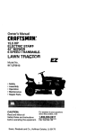
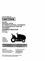
Owner's Manual
23.0 HP
ELECTRIC
START
50" MOWER (OPTIONAL ACCESSORY NOT INCLUDED WITH TRACTOR)
AUTOMATIC
GARDEN TRACTOR
Model No.
917.275000
•
•
•
•
•
Safety
Assembly
Operation
Maintenance
Repair Parts
CAUTION:
Read and follow all Safety
Rules and Instructions before
operating this equipment.
For answers to your questions
about this product, Call:
1-800-659-5917
Sears Craftsman Help Une
5 am - 5 pro, Mon- Sat
Sears, Roebuck and Co., Hoffman Estates, II 60179
Visit our Craftsman website:www.sears.com/craftsman
Warranty
...............................................
2
Maintenance
....................................... 19
Service and Adjustments.................... 23
Storage ............................................... 31
Troubleshooting ................................. 32
Repair Parts ........................................ 36
Parts Ordering ..................... Back Cover
Safety Rules ......................................... 3
Product Specifications .......................... 6
Assembly .............................................. 8
Operation ............................................ 12
Maintenance Schedule ...................... 19
LIMITED TWOYEAR WARRANTY ON CRAFTSMAN RIDING EQUIPMENT PARTS
For two (2) years from the date of purchase, if this Craftsman Riding Equipment is
maintained, lubricated and tuned up according to the instructionsin the owner's
manual, Sears will repair or replace, free of charge, any parts found to be defective in
matedal or workmanship. Warranty service is available free of charge by returning your
Craftsman riding equipment to your nearest Sears Service Center. In-home warranty
service is available but a trip charge will apply. This warranty applies only while this
product is in the United States.
This Warranty does not cover:.
• Expendable items which become wom during normal use, such as blades, spark
plugs, air cleaners, belts and oil filters.
• Tire replacement or repair caused by punctures from outside objects, such as nails,
thorns, stumps, or glass.
• Repairs necessary because of operator abuse, including but not limited to, damage
caused by towing objects beyond the capability of the riding equipment, impacting
objects that bend the frame or crankshaft, or over speeding the engine.
• Repairs necessary because of operator negligence, including but not limited to,
electrical and mechanical damage caused by improper storage, failure to use the
proper grade and amount of engine oil, failure to keep the deck clear of flammable
debris, or the failure to maintain the equipment according to the instructions conrained in the owner's manual.
• Engine (fuel system) cleaning or repairs caused by fuel determined to be contaminated or oxidized (stale). In general, fuel should be used within thirty (30) days of its
purchase date.
• Riding equipment used for commemial or rental purposes. A product is "used for
commemial purpose" if is used for any purpose other than single family household
dweUings or in usage where profit is made.
LIMITED 90 DAY WARRANTY ON BA'r'rERY
For ninety (90) days from date of purchase, if any battery included with this riding
equipment proves defective in material or workmanship and our testing determines the
battery will not hold a charge, Sears will replace the battery at no charge. Warranty
service is available free of charge by returning your Craftsman dding equipment to
your nearest Sears Service Center. In-home warranty service is available but a trip
charge will apply. This warranty applies only while this product is in the United States.
TO LOCATE THE NEAREST SEARS SERVICE CENTER ORTO SCHEDULE IN-HOME
WARRANTY SERVICE, SIMPLY CONTACT SEARS AT 1-800-4-MY-HOME
This Warranty gives you specific legal rights, and you may also have other rights which
may vary from state to state.
Seam, Roebuck and Co., D/817 WA, Hoffman Estates, IL 60179
2
MPORTANT: This cutting machine s capable of amputating hands and feet and
throwing..objects.Failure to observe the foUowing safety instructions coutd result in
sedous Injury or death.
I. GENERAL OPERATION
II. SLOPE OPERATION
• Read, understand, and fdik:_wa_
Slopes are a major factor related to loss-ofinstructionsin the manual and on the
control and tipover accidents, which can remachine before starting.
sult in severe injury or death. All slopes
require extra caution. If youcannot back up
• Only allow responsible adults.,who
familiar with the instructions,m operate
the slope or if you feel uneasy on it, do not
mow it.
the machine.
DO:
• Clear the area of objects such as rocks,
toys, wire, etc., which co_d be picked
• Mow up and down slopes, not across.
up and thrown by the blade.
• Remove obstacles such as rocks, tree
• Be sure the area is clear of other people
limbe, etc.
before mowi_. Stop machine if _jone
Watch for h_es, rata, o_"bumps. Uneven
enlel_ the area.
terrain could overturn the machine. Tall
• Never carry passengem.
grass can hide obstacles.
• Do not mow in reverse unless absolutely
Use slow speed. ChooSe a low gear sO
necessary. Always look down and
that you will not have to stop or shift
behind before and while backing.
while on the slope.
• Be aware of the mower discharge
Follow the manufacturer's recommendadirection and do not point it al anyone.
tions for wheel weights or counterDo not operate the mower without either
weights to improve stability.
the entire grass catcher or the guard in
Use extra care with grass catchers or
p(ace.
othar attachments. These can chan_
• Slow down before turning.
the stabil_ of the machine.
• Never leave a running machine
Keep all movement on the slopes slew
unattended. Always turn off blades, set
and gradual. Do not make sudden
parking brake, stop engine, and remove
changes in speed or direction.
keys before dismounting.
Avoid startingor stoppingon a slope. If
• Turn off blades when not mowing.
tires lose traction, disengage the blades
• Stop engine before removing grass
and proceed dowly straightdown the
catcher or unclogging chute.
slope.
• Mow only in daylight or good artificial
DO NOT:
light.
• Do not turn on stapesunless necessary,
• Do not operate the machine while under
and then, turn slowiy and gradually
the influence of alcohol or drugs.
downhill, if possible.
• Watch for trafficwhen operating near or
• Do not mow neer dropoffs, ditches,or
crossing roadways.
embankments. The mower could
• Use extra sere when loading or unloadsuddenly tum over if a wheel is over the
ing the machine into a trailer or truck.
edge of a cliffor ditch, or ff an edge
• Data indites
that operators, age 60
caves in.
years and above, are invOved in a large
• Do not mow on wet grass. Reduced
percentage of riding mower-related
traction could cause sliding.
injuries. These operators should
• Do noi try to stabilize the machine by
evaluate their ability to operate the riding
putting your foot on the ground.
mower Safely enough to protect them• Do not use grass catcher on steep
selves and others from serious inju_/.
slopes.
• Keep machine free of grass, reaves or
other debds build-upwhich can touch
hot exhaust / engine pads and bum. Do
not allow the mower deck to plow leaves
or other debds which can cause buildup to occur. Clean any oil or fuel
spillage before operating or stodng the
machine. Allow machine to cco_before
storage.
III.CHILDREN
Tragic accidents can occur if the operator
is not alert to the presence of children.
Children are often attracted to the
machine and the mowing activity. Never
assume that children will remain where
you last saw them.
• Keep children out ol the mowing area
and under the watchful care of another
responsible adult.
• Be alert and turn machine off if children
enter the area.
• Before and when backing, look behind
and down for small children.
• Never carry children. They may fall off
and be sedously injured or interfere
with safe machine operation.
• Never allow children to operate the
machine.
• Use extra care when approaching blind
comers, shrubs, trees, or other objects
that may obscure vision.
IV, SERVICE
• Use extra care in handling gasoline
and other fuels. They are flammable
and vapors are explosive.
- Use only an approved container.
-Never remove gas cap or add fuel
with the engine running. Allow
engine to cool before refueling. Do
not smoke.
-Never refuel the machine indoors.
- Never store the machine or fuel
container inside where there is an
open flame, such as a water heater.
• Never run a machine inside a closed
area.
• Keep nuts and bolts, especially blade
attachment botts, tight and keep
equipment in good condition.
• Never tamper with safety devices.
Check their proper operation regularly.
• Keep machine free of grass, leaves, or
other debris build-up. Clean oil or fuel
spillage. Allow machine to cool before
Storing.
• Stop and inspect the equipment if you
strike an object. Repair, if necessary,
before restarting.
• Never make adjustments or repairs
with the engine running.
• Grass catcher components are subject
to wear, damage, and deterioration,
which could expose moving parts or
allow objects to be thrown. Frequently
check components and replace with
manufacturer's recommended parts,
when necessary.
• Mower blades are sharp and can cut.
Wrap the blade(s) or wear gloves, and
use extra caution when servicing them.
• Check brake operation frequently.
Adjust and service as required,
• Be sure the area is clear of other
•
people before mowing. Stop machine if
anyone enters the area.
•
• Never carry passengers or children
even with the blades off.
•
• Do not mow in reverse unless absolutely necessary. Always look down
•
and behind before and while backing.
• Never carry children. They may fall off
•
and be seriously injured or interfere
with safe machine operation.
• Keep children out of the mowing area
and under the watchful care of another
responsible adult.
4
Be alert and turn machine off if children
enter the area.
Before and when backing, look behind
and down for small children.
Mow up and down slopes (15 ° Max),
not across.
Remove obstacles such as rocks, tree
limbs, etc.
Watch for holes, ruts, or bumps.
Uneven terrain could overturn the
machine. Tall grass can hide obstacles.
• Use slow speed. Choose a low gear so
that you will not have to stop or shift
while on the slope.
• Avoid starting or stopping on a slope. If
tires lose traction, disengage the
blades and proceed slowly straight
down the slope.
• If machine stops while going uphill,
disengage blades, shift into reverse
and back down slowly.
• DO not turn on slopes unless necessary, and then, turn slowly and gradually downhill, if possible.
_ CAUTION: Tow only the attachments
that are recommended by and comply
with specifications of the manufacturer of
your tractor. Use common sense when
towing. Operate only at the lowest
possible speed when on a slope. Too
heavy of a load, while on a slope, is
dangerous. "i']rescan lose traction with
the ground and cause you to lose control
of your tractor.
_bWARNING:
Engine exhaust, some of
its constituents, and certain vehicle
components contain or emit chemicals
known to the State of Califomia to cause
cancer and birth defects or other reproductive harm.
_.Look for this symbol to point out
important safety precautions. It means
CAUTIONIII BECOME ALERTIT! YOUR
SAFETY IS INVOLVED.
_WARNING:
Battery posts, terminals
and related eccessedas contain lead and
lead compounds, chemicals known to the
State of California to cause cancer and
birth defects or other reproductive harm.
Wash hands after handling.
_, CAUTION: In order to prevent
accidental starting when setting up,
transporting, adjusting or making repairs,
always disconnect spark plug wire and
place wire where it cannot contact spark
plug.
CAUTION: Do not coast down a hill
in neutral, you may lose control of the
tractor.
5
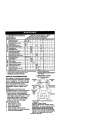
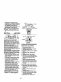
PRODUCT
SPECIFICATIONS
GASOLINE
CAPACITY
ANDTYPE:
OILTYPE
_PI-SF-SJ):
OIL CAPACITY:
We have competent, wen-trained technicians and the proper tools to service or
repair this tractor.
Please read and retain this manual. The
instructions will enable you to assemble
and maintain your tractor properly.
Always observe the =SAFETY RULES'.
REPAIR AGREEMENT
A Repair Agreement is available on this
product. Contact your nearest Sears
store for details.
3.5 GALLONS
UNLEADED
REGULAR
SAE 10W30
(ABOVE 32°F)
SAE 5W-30
(BELOW 32°F)
W/FILTER: 4.5PINTS
W/O FILTER:4.0PINT_
SPARK PLUG:
3AP: .030")
GROUND
CHAMPION
RC12YC
FORWARD: 5.8
SPEED(MPH):
TIRE
PRESSURE:
CHARGING
SYSTEM:
BA'[-FERY:
REVERSE: 2.1
FRONT:
14 PSI
REAR:
10 PSI
15AMPS @ 3600RPM
BLADE BOLT
TORQUE:
27-35 FT. LBS
CUSTOMER
RESPONSIBILITIES
• Read and observe the safety rules.
• Follow a regular schedule in maintaining, caring for and using your tractor.
• Follow the instructions under =Maintenance" and =Storage" sections of this
owner's manual.
_I, WARNING: This tractor is equipped
with an internal combustion engine and
should not be used on or near any
unimproved forest-covered, brush°
covered or grass-covered land unless the
engine's exhaust system is equipped with
a spark arrester meeting applicable local
or state laws (il any). If a spark arrester is
used, it should be maintained in effective
working order by the operator.
In the state of California the above is
required by law (Section 4442 o! the
California Public Resources Code).
Other states may have similar laws.
Federal laws apply on federal lands. A
spark arrester for the muffler is available
through your nearest Sears service
center (See REPAIR PARTS section of
this manual).
AMWHR:
35
MIN. CCA: 280
CASE SlZE:U 1R
i
CONGRATULATIONS on your pumhase
of a new tractor. It has been designed,
engineered and manufactured to give
you the best possible dependability and
performance.
Should you experience any problem you
cannot easily remedy, please contact a
Sears or other qualified service center.
6
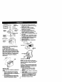
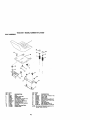
Steering Wheel
©
Steering Sleeve
Steering Wheel Insert
Steering Sleeve
Extension
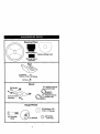
Seat
(1)Washer
17/32 x 1-3/16 x 12 Gauge
(1) Knob
Mower
(2) Flangecl c_>
(1)Front Plate _"
Assembly
o o;ing s
(2) Retainer Springs
j-_
_single
o_q:_
loop)
Gauge Wheels
(2) Washers 3/8
x 7/8 x 14 Gauge
(2) Shoulder
Bolts
_(2)
Wheels
7
Q(2)
Centerlock
Nuts
Video Cassette
Keys
Slope Sheet
€
(2) Keys
(1) Oil Drain Tube
Your new tractor has been assembled at the factory with exception of those parts left
unassembled for shipping purposes. To ensure safe and proper operation of your
tractor all parts and hardware you assemble must be tightened securely. Use the
correct tools as necessary to insure proper tightness.
TOOLS REQUIRED
ASSEMBLY
FOR
BEFORE REMOVINGTRACTOR
FROM SKID
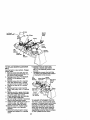
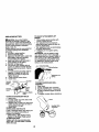
ATTACH STEERING WHEEL
1. Remove hex bolt, lock washer and
large flat washer from steering shaft.
2. Position frontwheels of the tractor so
they are pointing straight forward.
3. Stide the steering sleeve over the
steering shaft.
4. Align tabs and press steering sleeve
extension into bottom of steering
wheel.
5. Position steering wheel so cross bars
are horizontal (left to right) and slide
onto steering wheel adapter.
6. Secure steering wheel to steering
shaft with hex bolt, lock washer and
large fiat washer previously removed.
Tighten securely.
7. Snap steering wheel insert into center
of steering wheel.
8. Remove protective materials from
tractor hood and grill.
IMPORTANT: Check for and remove any
staples in skid that may puncture tires
where tractor is to roll off skid.
A socket wrench set will make assembly
easier. Standard wrench sizes you need
are listed below.
(1) 9/16"wrench
(1) Pliers
(1) 1/2"wrench
(1) Utility knife
(1) 3/4" socket with
drive ratchet
(1) Tire pressure gauge
When right or left hand is mentioned in
this manual, it means, from your point of
view, when you are in the operating
position (seated behind the steering
wheel).
TO REMOVETRACTOR
FROM
CARTON
UNPACK CARTON
1, Remove all accessible loose parts
and parts cartons from carton.
2, Cut, from top to bottom, along lines on
all four comers of carton, and lay
panels fiat.
3. Remove mower and packing materials.
4. Check for any additional loose parts
or cartons and remove.
8
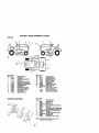
_._
Wheel insert
J_p_--_
Steedng
o-.-_-Lock Washer
_
LargeRat
Steering
Wa.r
Steering_
Sleeve _:_:::_--Tabs
Extension
I
Sleeve
_#'_:/,,.;,_
-, /
:
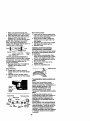
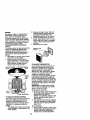
HOWTO SET UPYOURTRACTOR
CHECK BATTERY
1. Lift hood to raised position.
NOTE: If this battery is put into service
after month and year indicated on label
(label located between terminals) charge
battery for minimum of one hour at 6-10
amps. (See "BATTERY" in Maintenance
section of this manual for charging
instructions).
"'_
•
i!i: -_
3. Place seat on seat pan so head of
shoulder bolt is positioned over large
slotted hole in pan.
4. Push down on seat to engage
shoulder belt in slot and pull seat
towards rear of tractor.
5. Pivot seat and pan forward and
assemble adjustment knob and flat
washer loosely. Do not tighten.
6. Lower seat into operating position and
sit in seat.
7. Slide seat until a comfortable position
is reached which allows you to press
clutcWbmke pedal all the way down.
8. Get off seat without moving its
adjusted position.
9, Raise seat and tighten adjustment
knob securely.
*"
:
Seat Pan_
o,.sr
Label
'
INSTALL SEAT
Adjust seat before tightening adjustment
knob.
1. Remove adjustment knob and fiat
washer securing seat to cardboard
packing and set aside for assembly of
seat to tractor.
2. Pivot seat upward and remove from
the cardboard packing. Remove the
cardboard packing and discard.
NOTE: You may now roll or drive your
tractor off the skid. Follow the appropriate
instructionbelow to remove the tractor
from the skid.
TO ROLLTRACTOR
OFF SKID (See
Operation section for location and
function of controls)
1. Press lift lever plunger and raise
attachment lift lever to its highest
position.
2. Release parking brake by depressing
brake pedal.
3. Place freewheel control in freewheeling position to disengage transmission (See "TO TRANSPORT" in the
Operation section of this manual).
4. Roll tractor forward off skid.
TODRIVETRACTOR
OFFSKID(See
Operationsectionfor locationand
functionofcontrols)
_ILWARNING: Before starting read,
understand and follow all insfructions in
the Operation section of this manual. Be
sure tractor is in a well-ventilated area. Be
sure the area in front of tractor is clear of
other people and objects.
1. Be sure all the above assembly steps
have been completed.
2. Check engine oil level and fig fuel
tank with gasoline.
3. Place freewheel control in "transmission engaged" position.
4. Sit on seat in operating position,
depress brake pedal and set the
parking brake.
5. Press lift lever plunger and raise
attachment lift lever to its highest
position.
6. Start the engine. After engine has
started, move throttle control to idle
position.
7. Release parking broke.
8. Slowly move the motion control lever
forward and slowly drive tractor off
skid.
9, Apply brake to atop tractor and set
parking brake.
10.Turn ignition key to "OFF" position.
Continue with the instructions that follow.
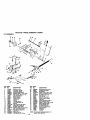
INSTALL MOWER AND DRIVE BELT
Be sure tractor is on level surface and
mower suspension arms are raised with
attachment lift control. Engage parking
brake.
1. Cut and remove ties securing antisway bar and belts. Swing anti-sway
bar to left side of mower deck.
2. Slide mower under tractor with
deflector shield to right side of tractor.
IMPORTANT: Check belt for proper
routingin all mower pulley grooves.
3. It equipped, turn height adjustment
knob counterclockwise until it stops.
4. Lower mower linkage with attachment
lift control,
5. Install belt into electric clutch pulley
groove.
6. Place the suspension arms on
outward pointing deck pins. Retain
with double loop retainer spring with
loops up as shown.
7. Install front p_ate assembly to tractor
suspension brackets and retain with
single loop retainer springs as shown.
8. Position front plate assembly between
front mower brackets. Raise deck and
plate assembly to align holes and
insert flanged pins. Secure pins with
double loop retainer springs between
the plate and mower brackets.
NOTE: To assist in locating hole in
flanged pin, the hole in pin is inline with
notch on head of pin. If necessary, move
mower side-to-side to give space
between plate and mower brackets.
IMPORTANT: Check belt for proper
routing in all mower pulley grooves.
9. Connect anti-sway bar to chassis
bracket under left Icotrest and retain
with double loop retainer spring.
10.If equipped, turn height adjustment
knob clockwise to remove slack from
mower suspension.
11 .Raise deck to highest position.
12.Assemble gauge wheels as shown
using long shoulder bolts, 3/8 washers, and 3/8-16 center Iocknuts.
Tighten securely.
13.Adjust gauge wheels before operating
mower as shown in the Operation
section of this manual.
CHECK TIRE PRESSURE
The tires on your tractor were overinflated
at the factory for shipping purposes.
Correct tire pressure is important for best
cutting performance.
• Reduce tire pressure to PSI shown in
"PRODUCT SPECIFICATIONS" section
of this manual.
CHECK MOWER LEVELNESS
For best cutting results, mower should be
properly leveled. See "TO LEVEL
MOWER HOUSING" in the Service and
Adjustments section of this manual.
CHECK FOR PROPER POSITION OF
ALL BELTS
See the figures that are shown for
replacing motion, mower drive, and
mower blade drive belts in the Service
and Adjustments section of this manual.
Verify that the belts are routed correctly.
10
Front
Suspension
SUS_Mowe
r Brackets
Bracket
Chassis
Bracket
Double Loop
Retainer
Front
Electric
Clutch
Pulley
Front plate
Shodder
Bolt
Wlleel
Single
Loop
Retainer
Springs
3/8
Washer
3/8-16
Double
Center
Loop
Locknut Retainer
Spring
Anti-Swa!
Bar
Use Pliers For
Retainer Springs
Deflector
Double Loop
Retainer Spring
\-Loop
deck pins)
(Outward pointing
Up
V'CHECKLIST
Before you operate end enjoy your new
tractor, we wish to assure that you receive
the best performance and satisfaction
from this Quality Product.
Please review the following checklist:
vAIl assembly instructions have been
completed.
./'No remaining loose parts in carton.
./Battery is properly prepared and
charged. (Minimum 1 hour at 6 amps).
./Seat is adjusted comfortably and
tightened securely.
./All tires are properly inflated. (For
shipping purposes, the tires were
overinflated at the factory).
./Be sure mower deck is property leveled
side-to-side/front-to-rear for best cutting
results. (Tires must be properly inflated
for leveling).
./'Check mower and drive belts. Be sure
they are routed propedy around pulleys
and inside all belt keepers.
./Check wiring. See that all connections
are still secure and wires are properly
clamped.
,/'Before driving tractor, be sure freewheel control is in drive position.
While learning how to use your tractor,
pay extra attention to the following
important items:
.4" Engine oil is at proper level.
./Fuel tank is filled with fresh, clean,
regular unleaded gasoline.
./Become familiar with all controls - their
_coation and function. Operate them
before you start the engine.
_/Be sure brake system is in safe
operating condition.
./It is important to purge the transmission
before operating your tractor for the first
time. Follow proper starting and
transmission purging instructions (See
"TO START ENGINE" and "PURGE
TRANSMISSION" in the Operation
section of this manual).
11
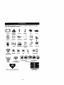
These symbols may appear on your tractor or in literature supplied with the product.
Learn and understand their meaning,
BATrERY
CAUTION OR
WARNtNG
REVERSE
FORWARD
ENGINE ON
ENGINE OFF
OIL PRESSURE
LIGHTS ON
OVER TEMP
tiGhT
FUEL
CHOKE
MOWER HEIGHT
PARKING BRAKE
LOCKED
UNLOCKED
r_'t R N H
A_ACHMEHT
CLUTCH ENGAGED
IGNmON
REVERSE
NEUTRAL
ATrACHMENT
CLUTCH DISENGAGEO
HIGH
FAST
SLOW
t
MOWER LIFT
L
LOW
PARKING BRAKE
KEEP AREA CLEAR
SLOPE HAZARDS
(SEE SAFETY RULES SECTION)
FREE WHEEL
(Automatic Mode_ only)
DANGER, KEEP HANDS AND FEET AWAY
12
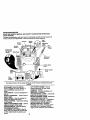
KNOWYOURTRACTOR
READ THIS OWNER'S MANUAL AND SAFETY RULES BEFORE OPERATING
YOUR TRACTOR
Compare the illustrationswith your tractor to familiarize yourself with the locations of
various controls and adjustments. Save this manual for future reference.
Light
Ammeter
Choke
ignition
Switch
Control
Throttle
Attachment
Clutch
Uft
Plunger
Control
Motion Drive
Belt Tension
Brake Pedal
Handle
Attachment
LiftLever
Brake
Lever
Height
Adjustment
Knob
Lever
Free
Wheel
Control
Our tractors conform to the safety standards of the American National Standards
Institute.
A'n'ACHMENT CLUTCH SWITCH Used to engage the mower blades, or
other attachments mounted to your
tractor.
LIGHT SWITCH -Turns the headlights on
and off.
THRO'I-I'LE CONTROL - Used to control
engine speed.
BRAKE PEDAL - Used for braking the
tractor and starting the engine.
CHOKE CONTROL - Used when starting
a cold engine.
HEIGHT ADJUSTMENT KNOB - Used to
adjust the mower cutting height.
IGNDON SWITCH - Used for starting
and stopping the engine.
A'n'ACHMENT UFT LEVER - Used to
raise, lower, and adjust the mower deck
or other attachments mounted to your
tractor.
LIFT LEVER PLUNGER - Used to
release attachment lift lever when
changing its position.
AMMETER - Indicates charging (+) or
discharging (-) of battery.
PARKING BRAKE LEVER - Locks brake
pedal into the brake position.
MOTION CONTROL LEVER - Selects the
speed and direction of tractor.
FREEWHEEL CONTROL - Disengages
transmission for pushing or slowly
towing the tractor with the engine off.
MOTION DRIVE BELTTENSION
HANDLE-Used when changing motion
drive belt and, if necessary, starting
engine under extremely cold conditions.
13
I
The operation of any tractor can result in foreign objects thrown into
the eyes, which can result in severe eye damage. Always wear safety
glasses or eye shields while operating your tractor or performing any
adjustments or repairs. We recommend a wide vision safety mask over
spectacles or standard safety glasses.
HOWTO USEYOURTRACTOR
TO SET PARKING BRAKE
Your tractor is equipped with an operator
presence sensing switch. When engine
is running, any attempt by the operator to
leave the seat without first se_ng the
parking brake will shut off the engine.
1. Depress brake pedal into full "BRAKE"
position and hold.
2. Place parking brake lever in =ENGAGED" position and reteass
pressure from brake pedal. Pedal
should remain in "BRAKE" position.
Make sure parking brake will hold
tractor
secure.
Push-tnto AttachmentClutch
Choke
='_Isen-a-e" SwitchPullOut to
C'ontroL_
y
"Engage"
Control_j_
.J'_,lj_-'_
_=j
Brake_'_
Adjustmenl"
._
/ _Knob
'
ParkingBrake
SrakePe_lal
"Engaged" Position
"Drive Position "Dis gaged"Position
STOPPING
MOWER BLADES • To stop mower blades,move attachment clutch switch to "DISENGAGED"
position,
GROUND DRIVE • To stop ground ddve, depress brake
pedal into full =BRAKE" position.
IMPORTANT: The motion control lever
returns to neutral (N) position when the
brake pedal is fully depressed,
ENGINE -
• Never use choke to stop engine.
IMPORTANT: Leaving the ignition switch
in any position other than "OFF" will
cause the battery to be discharged,
(dead).
NOTE: Under certain conditions when
tractor is standing idle with the engine
running, hot engine exhaust gases may
cause "browning" of grass. To eliminate
this possibility, always stop engine when
stopping tractor on grass areas.
_CAUTION:
Always stop tractor
completely, as described above, before
leaving the operator's position; to empty
grass catcher, etc.
TO USE TH RO'I'I'LE CONTROL
Always operate engine at full throttle.
• Operating engine at less than full
throttle reduces the battery charging
rate.
• Full throttle offers the best mower
performance.
TO USE CHOKE CONTROL
Use choke control whenever you are
starting a cold engine. Do not use to start
a warm engine.
• To engage choke control, pull knob out.
Slowly push knob in to disengage.
_MOVE
FORWARD AND BACKWARD
CAUTION: Do not attempt to operate
motion control lever when the parking
brake is set or when the brake pedal is
depressed. Doing so may result in
misadjustment to the drive control system.
The direction and speed of movement is
controlled by the motion control lever.
1. Start tractor with motion control lever
in neutral (N) position.
2. Release parking brake.
3. Slowly move motion control lever to
desired position.
TO ADJUST MOWER CuI"rlNG HEIGHT
The cutting height is controlled by turning
the height adjustment knob in desired
direction.
• Turn knob clockwise (,"_) to raise
cutting height,
• Turn knob counterclockwise (I,,'_) to
lower cutting height.
• Move throttle control to slow position.
NOTE: Failure to move throttle control to
slow position and allowing engine to idle
before stopping may cause engine to
"backfire".
• Turn ignition key to =OFF_ position and
remove key. Always remove key when
leaving tractor to prevent unauthorized
use.
14
The cutting height range is approximately
1-1/2" to 4-1/2". The heights are measured from the ground to the blade tip
with the engine not running.
These heights are approximate and may
vary depending upon soil conditions,
height of grass and types of grass being
mowed.
• The average lawn should be cut to
approximately 2-1/2 inches during the
cool season and to over 3 inches
during hot months. For healthier and
better looking lawns, mow often and
after moderate growth.
• For best cutting performance, grass
over 6 inches in height should be
mowed twtco. Make the first cut
relatively high; the second to desired
height.
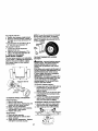
TO ADJUST GAUGE WHEELS
Gauge wheels are properly adjusted
when they ere slightly off the ground
when mower is at the desired cutting
height in operating position. Gauge
wheels then keep the deck in proper
position to help prevent scalping in most
terrain conditions.
NOTE: Adjust gauge wheels with tractor
on a flat level surface.
1. Adjust mower to desired cutting
height.
2. Lower mower with lift control. Remove rear retainer spring and clevis
pin which secure each gauge wheel.
3. Lower gauge wheels to ground.
Raise gauge wheels slightly to align
holes in bracket and gauge wheel bar
and insert clevis pins. Gauge wheels
should be slightly off the ground.
4. Replace retainer springs into clevis
pins.
Retainer ClevisPin
Spring \
Gauge
Bar
Gaug
Wheel _
•
1. Select desired height of cut.
2. Lower mower with attachment lift
control.
3. Start mower blades by engaging
attachment clutch control.
TO STOP MOWER BLADES disengage attachment clutch control.
_CAUTION:
Do not operate the mower
without either the entire grass catcher, on
mowers so equipped, or the deflector
shield in place.
AttachmentClutch
Switch PullOutto
=Engage"
AttachemntUIt
LeverHighPosition
..;:::_L0w
PosilJ0n
to
"Disengage"
TO OPERATEON HILLS
Deflector
Shield
X1L
I_CAUTION:
Do not drive up or down
hills with slopes greater than 15° and do
not drive across any slope.
• Choose the slowest speed before
starting up or down hills.
• Avoid stopping or changing speed on
hills.
• If stopping is absolutely necessary,
push brake pedal quickly to brake
position and engage parking brake.
IMPORTANT: The motion control lever
returns to neutral (N) position when the
brake pedal is depressed.
• To restart movement, slowly release
perking brake and brake pedal.
• Slowly move motion control lever to
slowest setting.
• Make all turns slowly.
Brack,
TO OPERATE MOWER
Yourtractor is equipped with an operator
presence sensing switch. Any attempt by
the operator to leave the seat with the
engine running and the attachment clutch
engaged will shut off the engine.
15
TOTRANSPORT
When
pushing
ortowingyourtractor,
be
suretodisengage
transmission
by
placing
freewheel
controlin freewheeling
position. Free wheel control is located at
the rear drawbar of tractor.
1. Raise attachment lift to highest
position with attachment lift control.
2. Pull freewheel control out and into the
slot and release so it is held in the
disengaged position.
• Do not push or tow tractor at more than
two (2) MPH.
• To reengage transmission, reverse
above procedure.
NOTE: To protect hood from damage
when transporting your tractor on a truck
or a trailer, be sure hood is ctosod and
secured to tractor. Use an appropriate
means of tying hood to tractor (rope, cord,
etc.).
TOWING CARTS AND OTHER A'I'rACHMENTS
Tow only the attachments that are
recommended by and comply with
specificationsof the manufacturer of your
tractor. Use common sense when towing.
Too heavy of a load, while on a slope, is
dangerous. Tires can lose traction with
the ground and cause you to rose control
of your tractor.
BEFORE STARTING THE ENGINE
CHECK ENGINE OIL LEVEL
The engine in your tractor has been
shipped, from the factory, already filled
with summer weight oil.
1. Check engine oil with tractor on level
ground.
2. Unthread and remove oil fill cap/
dipstick; wipe oil off. Reinsert the
dipstickinto the tube and rest oil fill
cap on the tube. Do not thread the
cap onto the tube. Remove and read
oil level. If necessary, add oil until
"FULL" mark on dipstick is reached.
Do not overfill.
• For cold weather operation you should
change oi( for easier starting(See "OIL
VISCOSITY CHART" in the Maintenance section of this manual).
• To change engine oil, see the Maintenanse section in this manual.
ADD GASOUNE
• Fill fuel tank. Use fresh, clean, regular
unleaded gasoline with a minimum of
87 octane. (Use of leaded gasoline
will increase carbon and lead oxide
deposits and reduce valve life). Do not
mix oil with gasoline. Purchase fuel in
quantities that can be used within 30
days to assure fuel freshness.
IMPORTANT: When operating in
temperatures below 32°F(0°C), usa fresh,
clean winter grade gasoline to help
insure good cold weather starting.
_,WARNING:
Exper_enseindicates that
alcohol blended fuels (called gasohol or
using ethanol or methanol) can attract
moisture which leads to separation and
formation of acids during storage. Acidic
gas can damage the fuel system of an
engine while in storage. To avoid engine
problems, the fuel system should be
emptied before storage of 30 days or
longer. Drain the gas tank, start the
engine and let it run until the fuel tines
and carburetor are empty. Use fresh fuel
next season. See Storage Instructionsfor
additional information. Never use engine
or carburetor cleaner products in the fuel
tank or permanent damage may occur.
_I, CAUTION: Fill to bottom of gas tank
filler neck. Do not overfill. Wipe offany
spilled oil or fuel. Do not store, spill or
use gasoline near an open flame.
TO STAR3" ENGINE
Whec startingthe engineforthe firsttimeor if
the enginehas run outof fuel,it w_lltake extra
cranldn__me to move fualfrom the tankto
the enghne.
1. Be sure freewheel control is in the
transmission engaged position.
2. Sit on seat in operating position,
depress brake pedal and set parking
brake.
3, Move attachment clutch to "DISENGAGED" position.
4. Move throttle control to last position
5. Pull choke control out for a cold
engine start attempt. For a warm
engine start attempt the choke control
may not be needed.
16
NOTE: BeforestarUng,read the warm and
cold startingproceduresbelow.
6. Insert key into ignition and turn key
clockwise to =START" position and
release key as soon as engine starts.
Do not run starter continuously for
more than fifteen seconds per minute.
If the engine does not start after
several attempts, push choke control
in, wait a few minutes and try again. If
engine still does not start, pull the
choke control out and retry.
WARM WEATHER STARTING (50° F and
above)
7. When engine starts, stowiy push
choke control in until the engine
begins to run smoothly. If the engine
starts to run roughly, pull the choke
control out slightly for a few seconds
and then continue to push the control
in slowly.
• The attactvsentsand groundddvecan
now be used. if the enginedoes notacsept
tbe load, restartbe engine anclalicwit to
warm up for one minuteusingthe choke
as described above.
COLD WEATHER STARTING (50° F and
below)
7. When engine starts, slowly push
choke control in until the engine
begins to run smoothly. Continue to
push the choke control in small steps
allowing the engine to accept small
changes in speed and load, until the
choke control is fully in. If the engine
starts to run roughly, pullthe choke
control out slightly for a few seconds
and then continue to push the control
in slowly. This may require an engine
warm-up pedod from several seconds
to several minutes, depending on the
temperature.
NOTE: In extreme cold conditions, if
engine will not start you may need to
disengage the motion drive belt as
follows:
1. Be sure parking brake is engaged.
2. Remove retainer spdng from the drive
belt tension handle to relieve belt
tension.
3. Start engine and allow it to warm up
for three (3) minutes.
4. Shut-off engine and engage parking
brake.
5. Engage drive belt tension handle and
replace the retainer spdng.
AUTOMATICTRANSMISSION WARM UP
Before ddving the unit in cold weather,
the transmission should be warmed up as
follows:
1. Be sure the tractor is on level ground.
2. Place the motion control lever in
neutral. Release the parking brake
and let the brake slowly return to
operating position.
3. Allow one minute for transmission to
warm up. This can be done dudng the
engine warm up period.
• The attachments can be used dudng
the en_line warm-up pedod after the
transmtssion has been warmed up and
may require the choke control be
pulled out slightly.
NOTE: If at a htgh altitude (above 3000
feet) or in cold temperatures (below 32 F)
the carburetor fuel mixture may need to
be adjusted for best engine performance.
See TO ADJUST CARBURETOR" in the
Service and Adjustments section of this
manual.
PURGETRANSMISSION
_,CAUTION:
Never engage or disengage freewheel lever while the engine is
running.
To ensure proper operation and performance, it is recommended that the
transmission be purged before operating
tractorfor the first time. This procedure will
remove any trapped air inside the transmissionwhich may have developed dudng
shippingof your tractor.
IMPORTANT: Should your transmission
require removal for service or replacement,
it should be purged after reinstallation
before operatingthe tractor.
1. Place tractor safely on level surface
with engine off and parking brake set.
2. Disengage transmission by placing
freewheel control in freewheeling
position (See "TO TRANSPORT" in
this section of manual).
3. Sitting in the tractor seat, start engine.
After the engine is running, move
throttle control to slow position.
Disengage parking brake.
4. Move motion control lever to full
forward position and hold for five (5)
seconds. Move lever to full reverse
position and hold for five (5) seconds.
Repeat this procedure three (3) times.
NOTE: During this procedure there will be
no movement of drive wheels. The air is
being removed from hydraulicdrive
system.
17
5. Move motion control lever to neutral
(N) position. Shut- off engine and set
parking brake.
6. Engage transmission by placing
freewheel control in driving position
(See "TO TRANSPORT" in this section
of manual).
7. Sitting in the tractor seat, start engine.
After the engine is running, move
throttle control to half (1/2) speed.
Disengage parking brake.
8. Slowly move motion control lever
forward, after the tractor moves
appmximataly five (5) feet, slowly
move motion control lever to reverse
position. After the tractor moves
approximately five (5) feet return the
motion control lever to the neutral (N)
position. Repeat this procedure with
the motion control lever three (3)
times.
Your tractor is now purged and now ready
for normal operation.
MOWINGTIPS
• Tire chains cannot be used when the
mower housing is attached to tractor.
• Mower should be propedy leveled for
best mowing performance. See "TO
LEVEL MOWER HOUSING" in the
Service and Adjustments section of this
manual.
• The left hand side of mower should be
used for trimming.
• Ddve so that clippings are discharged
onto the area that has been cut. Have
the cut area to the right of the tractor.
This will result in a more even diStribution of clippings and more uniform
cutting.
• When mowing large areas, start by
turning to the right so that clippings will
discharge away from shrubs, fences,
driveways, etc. After one or two
rounds, mow in the opposite direction
making left hand turns until finished.
• It grass is extremety tall, it should be
mowed twice to reduce load and
possible fire hazard from dried clippings. Make first cut relatively high; the
second to the desired height.
• Do not mow grass when it is wet. Wet
grass will plug mower and leave
undesirable clumps, Allow grass to dry
before mowing.
• Always operate engine at fu|l throttle
when mowing to assure better mowing
performance and proper discharge of
material. Regulate ground speed by
selecting a low enough gear to give the
mower cutting performance as well as
the quality of cut desired.
• When operating attachments, select a
ground speed that will suit the terrain
and give best performance of the
attachment being used,
18
1 . Cl_ngl
rn_e Olten when _,tg
undo4- m hem_
lold ¢r kl l_,gh mT_nt
GENERAL RECOMMENDATIONS
The warranty on thistractor does not cover
items that have been subjected to operator
abuse or negligence. To receive full value
from the warranty, operator must maintain
tractor as instructedin this manual.
Some adjustments will need to be made
pedodically to properly maintain your
tractor.
All adjustments in the Service and
Adjustments section of this manual should
be checked at least once each season.
• Once a year you should replace the
spark plug, dean or replace air filter, and
check blades and belts for wear. A new
spark plug and clean air filter assure
proper alr-fual mixture and help your
engine run better and last longer.
BEFORE EACH USE
1. Check engine oil level.
2. Check brake operation.
3. Check tire pressure.
4. Check operator presence and
intedock systems for proper operation.
5. Check for loose fasteners.
mmFe.ft_
5. If e_JIr_lld _
IdjultlbM
i_
6. N_ r_llnld
If _Fal_
w_lh m_nbmanCe-hel
7 * Tight _, kent _
plv_ bo/t to 3_ P-J_4, r_.
DO not o_ten.
bettmy.
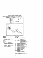
LUBRICATION CHART
_)Tie Rod BallJoints
_
_ Spindle_l/.
....... _
•)Front Wheelr-_
®st_an_
_.'_
(_ Spindle
Zerk
XJ_Front
Wheel
FX/
I
Bearing\ "_='_
Sector
)_ ___ng
Gear
_/
Teeth
__._= _ __
Zerk
_Engine
•Spray SiliconeLubriant{Move Bootsto
Lubricate)
_Ganerel PurposeGrease
@Retsr to Maintenance=ENGINE"Section
IMPORTANT: Do notoil or greasethe pivot
pointswhichhave specialnyk_ bearings.
Viscouslubdcantewill attractdustand dirt
thatwill shortenthe life ofthe eerf-lubricattng
bastings. If youfeel they mustbe lubricated,
19
use only a dry, powdered graphite type
lubricant spaflngly.
TRACTOR
Always observe safety rules when
pedorming any maintenance.
BRAKE OPERATION
If tractor requires more than six (6) feet
stopping distance at high speed in
highest gear, then brake must be adjusted. (See "TO ADJUST BRAKE" in the
Service and Adjustments section of this
manual).
TIRES
• Maintain proper air pressure in all tires
(See =PRODUCT SPECIFICATIONS"
section of this manual).
• Keep tires free of gasoline, oil, or insect
control chemicals which can harm
rubber.
• Avoid stumps, stones, deep ruts, sharp
objects and other hazards that may
cause tire damage.
NOTE: To seal tire punctures and prevent
Itat tires due to slow leaks, tire sealant
may be purchased from your local parts
dealer. Tire sealant also prevents tire dry
rot and corrosion.
OPERATOR
PRESENCE
SYSTEM
Be sure operator presence and intedock
systems are working properly. If your
tractor does not function as described,
repair the problem immediately.
• The engine should not start unless the
brake pedal is fully depressed and
attachment clutch control is in the
disengaged position.
• When the engine is running, any
attempt by the operator to leave the
seat without first setting the parking
brake should shut off the engine.
• When the engine is running and the
attachment clutch is engaged, any
attempt by the operator to leave the
seat should shut off the engine.
• The attachment clutch should never
operate unless the operator is in the
seat.
BLADE CARE
For best resultsmower blades must be
kept sharp. Replace bent or damaged
blades.
BLADE REMOVAL
IMPORTANT: To ensure proper assembly,
center hole in blade must align with star
on mandrel assembly.
4. Reassemble hex belt, lock washer
and fiat washer in exact order as
shown.
5. Tighten bolt securely (27-35 Ft. Lbs.
torque).
IMPORTANT: Brads bolt is grade 8 heat
treated.
MandrelAssembly
Trailing_ Blade Center j_
Edge Up___
Hole _
_)
_--_-'Hex Bolt(Grade)_'_
*A Grade 8 heattreatedbo_tcan be identified
bysix lines on _e bolthead.
TO SHARPEN BLADE
NOTE: We do not recommend sharpening blade - but if you do, be sure the
blade is balanced.
Care should be taken to keep the blade
balanced. An unbalanced blade will
cause excessive vibration and eventual
damage to mower and engine.
• The blade can be sharpened with a file
or on a grinding wheel. Do not attempt
to sharpen while on the mower.
• To check blade balance, you will need
a 5/8" diameter steel bolt, pin, or a cone
belancer. (When using a cone baianoer, follow the instructions supplied
with belancer.)
NOTE: DO not use a nail for balancing
blade. The lobes of the center hole may
appear to be centered, but are not.
• Slide blade on to an unthreaded
portion of the steel bolt or pin and hold
the belt or pin parallel with the ground.
If blade is balanced, it should remain in
a hodzontal position. If either end of
the blade moves downward, sharpen
the heavy end until the blade is
Blade
1. Raise mower to highest position to
BATrERY
CenterHole
allow access to blades.
2. Remove hex bolt, lock washer and flat
Your tractor has a battery charging system
which is sufficiant for normal use. Howwasher secudng blade.
3. install new or resharpeoed blade with
ever, periodic charging of the battery with
trailing edge up towards deck as
an automotive charger will extend its life.
shown.
2O
• Keep
battery
and
ENGINE
LUBRICATION
Only use high quality detergent oil rated
with API service classification SF-SJ.
Select the oil's SAE viscosity grade
according to your expected operating
temperature.
terminals clean.
• Keep battery bolts tight.
Keep small vent holes open.
• Recharge at 6-10 amperes for 1 hour.
NOTE: The original equipment battery on
your tractor is maintenance free. Do not
attempt to open or remove caps or covers.
Adding or checking level of electrolyte is
not necessary.
TO CLEAN BATTERY AND TERMINALS
Corrosion and dirt on the battery and
terminals can cause the battery to "leak"
power.
1, Remove terminal guard.
2, Disconnect BLACK battery cable first
then RED battery cable and remove
battery from tractor.
3. Rinse the battery with plain water and
dry.
4. Clean terminals and battery cable
ends with wire brush until bright.
5. Coat terminals with grease or petroleum jelly.
6. Reinstall battery (See =REPLACING
BATTERY" in the SERVICE AND
ADJUSTMENTS section of this
manual).
I
c _/_ERATU_E
_
_
_
_o
BF_:_E
_
_
NEXT OIL C_NQE
_1
Change the oil after every 50 hours of
operation or at least once a year if the
tractor is not used for 50 hours in one
year.
Check the crankcase oil level before
starting the engine and after each eight
(8) hours of operation. Tighten oil fillcap/
dipstick securely each time you check the
oil level.
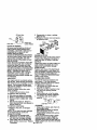
TO CHANGE ENGINE OIL
Determine temperature range expected
before oil change. All oil must meet API
service classification SF-SJ.
• Be sure tractor is on level surface.
• Oil will drain more freely when warm.
• Catch oil in a suitable container.
1. Remove oil fill cap/dipstick. Be careful
not to allow dirt to enter the engine
when changing oil.
2. Remove cap from end of drain valve
and install the drain tube onto the
fitting,
3. Unlock drain valve by pushing upward
slightly and turning counterclockwise.
4. To open, pull down on the drain valve.
5. After oil has drained completely, Nose
and lock the drain valve by pushing
upward and turning clockwise until the
pin is in the locked position as shown.
6. Remove the drain tube and replace
the cap onto to the end of the drain
valve.
7. Refill engine with oil through oil fill
dipsticktube. Pour slowly. Do not
overfill. For approximate capacity see
=PRODUCT SPECIFICATIONS"
section of this manual.
8. Use gauge on oil fill cap/dipstick for
checking level. Insert dipstick into the
tube and rest the oil fill cap on the
tube. Do not thread the cap onto the
tube when taking reading. Keep oil
at "FULL" line on dipstick. Tighten cap
onto the tube securely when finished.
V-BELTS
Check V-belts lor deterioration and wear
after 100 hours of operation and raptece
if necessary. The belts are not adjustable.
Replace belts if they begin to slip from
wear.
TRANSAXLE COOLING
The transmission fan and cooling fins
should be kept clean to assure proper
cooling.
Do not attempt to clean fan or transmission while engine is running or while the
transmission is hot. To prevent possible
damage to seals, do not use high
pressure water or steam to clean
transaxle.
• Inspect cooling fan to be sure fan
blades are intact and clean.
• Inspect cooling fins for dirt, grass
clippings and other matarials, To
prevent damage to seals, do not use
compressed air or high pressure
sprayer to clean cooling fins.
TRANSAXLE PUMP FLUID
The transaxle was sealed at the factory
and fluid maintenance is not required for
the life of the transaxle. Should the
transaxle ever leak or require servicing,
contact your nearest authorized service
center/department.
"_
RANGE AN_OIPAT_D
21
Oil Drain Valve
Cap_
D i -_
re n Tube f
_
_'_
9. Reassemble air cleaner, cartridge
plate, and nut.
1O.Reinstall air cleaner cover and secure
by tightening knob.
= _CIosedand
"Locked Position
CLEAN AIR SCREEN
Air screen must be kept free of dirt and
chaff to prevent engine damage from
overheating. Clean with a wire brush or
compressed air to remove dirt and
stubborn dried gum fibers.
CLEAN AIR INTAKE/COOUNG AREAS
To insure proper cooling, make sure the
grass screen, cooling fins, and other
external surfaces of the engine are kept
clean at all times.
Every 100 hours of operation (more often
under extremely dusty, dirty conditions),
remove the blower housing and other
cooling shrouds. Clean the cooling fins
and external surfaces as necessary. Make
sure the cooling shrouds are reinstalled.
NOTE: Operating the engine with a
blocked grass screen, dirty or plugged
cooling fins, and/or cooling shrouds
removed will cause engine damage due
to overheating.
AIR FILTER
Your engine will not run properly using a
dirty air filter. Clean the foam pre-cleaner
after every 25 hours of operation or every
season. Service paper cartndge every
100 hours of operation or every season,
whichever occurs first.
Service air cleaner more often under
dusty conditions.
1. Loosen knob and remove cover.
TO SERVICE PRE-CLEANER
2. Slide foam pre-cleaner off cartridge.
3. Wash it in liquid detergent and water.
4. Squeeze it dry in a clean cloth. Allow
it to dry.
5. Saturate it in engine oil. Wrap it in
clean, absorbent cloth and squeeze to
remove excess oil.
TO SERVICE CARTRIDGE
Replace a dirty, bent, or damaged
cartridge.
NOTE: Do not wash the paper certridge
or use pressurized air, as this will
damage the cartridge.
6. Remove nut and cartridge plate.
7. Reinstall the pre-cteaner (cleaned
and oiled) over the paper cartridge.
8. Check rubber seal for damage and
proper position around stud. Replace
if necessary.
22
Foam
Pre-Cfeaner
Cartridge
Nut
ENGINE OIL FILTER
Replace the engine oil filter every season
or every other oil change if the tractor is
used more than 100 hours in one year.
MUFFLER
Inspect and reptsce corroded muffler and
spark arrester (if equipped) as it could
create a fire hazard and/or damage.
SPARK PLUGS
Replace spark plugs at the beginning of
each mowing season or after every 100
hours of operation, whichever occursfirst.
Spark plug type and gap setting are
shown in "PRODUCT SPECIFICATIONS"
section of this manual.
IN-LINE FUEL FILTER
The fuel filter should be replaced once
each season. If fuel filter becomes
clogged, obstructing fuel flow to carburetor, replacement is required.
1. With engine cool, remove filter and
plug fuel line sections.
2. Place new fuel filter in position in fuel
line with arrow pointing towards
carburetor.
3. Be sure there are no fuel line leaks
and clamps are property positioned.
4. Immediately wipe up any spilled
gasoline. Cl_lam
p
Fuel Fitter
CLEANING
of all ford_jn matter.
Keep finished surfaces and wheels
i free
lean
battery,
ofengine,
all gasoline,
oil, seat,
etc. finish, etc.
Protect painted surfaces with automotive type wax.
We do not recommend using a garden
hose to clean your tractor unless the
electrical system, muffler, air filter and
carburetor are covered to keep water out.
Water in engine can result in a shortened
engine life.
_bCAUTION:
BEFORE PERFORMING ANY SERVICE OR ADJUSTMENTS:
1. Depress brake pedal fully and set parking brake.
2. Place attachment clutch in "DISENGAGED" position.
3. Turn ignition key =OFF" and remove key.
4. Make sure the blades and all moving parts have completely stopped.
5. Disconnect spark plug wire from spark plug and p_acewire where it cannot
come in contact with plug.
TRACTOR
TO REMOVE MOWER
1. Place attachment clutch in =DISENGAGED" position.
2. Turn height adjustment knob to lowest
setting.
3. Lower mower to its lowest position.
4. Remove retainer spring holding antiswaybar to chassis bracket and
disengage anti-swaybar from bracket.
5. Remove four retainer springs from
front plate assembly and remove
plate.
6. Remove retainer spdngs from
suspension arms at deck and disengage arms from deck.
7. Raise attachment lift to its highest
position.
8. Slide mower forward and remove belt
from alectdc clutch pulley.
9, Slide mower out from under right side
of tractor.
TO INSTALL MOWER
Follow procedure descdbed in "INSTALL
MOWER AND DRIVE BELT in the
Assembly section of this manual.
TO LEVEL MOWER HOUSING
Adjust the mower while tractor is parked
on level ground or driveway, Make sure
tires are propedy inflated (See PRODUCT SPECIFICATIONS" section of this
manual). If tires ara over or
undednflated, you will not properly adjust
your mower.
SIDE-TO-SIDE ADJUSTMENT
• Raise mower to its highest position.
• Measure height from bottom edge of
mower to ground level at front comers
of mower. Distance "A"on both sides
of mower should be the same.
Suspension
Electric
Front Mower
Bracket
Chassis
Bracket
Clutch Pulley
Front
Plate
Retainer
_prings
(BothSides)
Anti-Sway
Bar
Bracket
Retainer Springs
23
• II adjustment is necessary, make
adjustment on one side of mower only.
• To raise one side of mower, tighten lift
link adjustment nut on that side.
• To lower one side of mower, loosen lift
link adjustment nut on that side.
NOTE: Each full turn of adjustment nut
will change mower height about 3/16".
• Recheck measurements after adjusting.
BottomEdgeof
_
oo
_
Mandrel
BothFrontUnks Shouldbe Equalin Length
BottomEdge of
Nut "H_
FRONT-TO-BACK ADJUSTMENT
IMPORTANT: DECK MUST BE LEVEL
SIDE-TO-SIDE. if the following front-toback adjustment is necessary, be sure to
adjust both front links equally so mower
will stay level side-to-side.
To obtain the best cutting results, the
mower housing should be adjusted so
the front is approximately 1/8" to 1/2"
lower than the rear when the mower is in
its highest position.
Check adjustment on right side of tractor.
Measure distance "F" directly in front of
and behind the mandrel at bottom edge
of mower housing as shown.
• Before making any necessary adjustments, check that both front links are
equal in length.
• If links are not equal in length, adjust
one link to same length as other link.
• To lower front of mower housing,
loosen nut "G" on both front links an
equal number of turns.
• When distance =F" is 1/8" to 1/2" lower
at front than rear, tighten nut "H"
against trunnion on both front links.
• To raise front of mower housing,
loosen nut =H" from trunnion on both
front links. Tighten nut "G" on both
front links an equal number of tams.
• When distance "F" is 1/8" to 1/2" lower
at frontthan rear, tighten nut =H"
against trunnion on both front links.
NOTE: Each full turn of nut "G" will
change dim. "F" by approximately 3/8".
• Recheck side-to-side adjustment.
Nut "G"
Trunnion "_
Front Plate
Assembly
TO REPLACE
MOWER
DRIVE
BELT
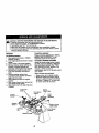
MCNVER DRIVE BELT REMOVAL
1. Park tractor on a level surface.
Engage parking brake.
2. Remove screws from L.H. mandrel
cover and remove cover.
3. Roll belt over the top of LH. mandrel
pulley.
4. Remove belt from electric clutch
pulley.
5. Remove belt from idler pulleys.
6. Remove any dirt or grass clippings
which may have accumulated around
mandrels and entire upper deck
surface.
7. Check pdmary idler arm and two
idlers to see that they rotate freely.
8. Be sure spring is securely hooked to
primary idler arm and bolt in mower
housing.
MOWER DRIVE BELT INSTALLATION
9. Install bolt in both idlers. Make sure
belt is in both belt keepers at the idlers
as shown.
10.Install new belt onto electric clutch
pulley.
11. Roll belt into upper groove of L.H.
mandrel pulley.
12.Carefully check belt muting making
sure bolt is in the grooves correctly
and inside belt keepers.
13.Reassemble L.H. mandrel cover.
24
Screws
Electdc
Clutch
Putley
Left Hand
Mandr_
Idler Pulleys
Spdng
Bolt in
Housing
Left
Hand
Mandrel
Mower
Ddve Belt
Pdmary
Belt
Keepers
TO REPLACE MOWER BLADE DRIVE
BELT
Park the tractoron level surface. Engage
parking brake.
1. Remove mower ddve belt (Sea TO
REPLACE MOWER DRIVE BELT" in
this section of this manual).
2. Remove mower (See "TO REMOVE
MOWER" in this section of this
manual).
3. Remove screws from R.H. mandrel
cover and remove cover. Unhook
spring from bolt on mower housing.
4. Carefully roll belt off R.H. mandrel
pulley.
5. Remove belt from center mandrel
pulley, idler pulley, and L.H. mandrel
pulley.
6. Remove any dirt or grass which may
have accumulated around mandrels
end entire upper deck surface.
7. Check secondary idler arm and idler
to see that they rotate freely.
8. Be sure spring is hooked in secondary
idler arm and sway-bar bracket.
9. Install new belt in lower groove of LH.
mandrel pulley, idler pulley, end
center mandrel pulley as shown.
10.Roll belt over R.H. mandrel pulley.
Make sure belt is in all grooves
properly.
11.Reconnect spdng to belt in mower
housing and reinstall R.H. mandrel
cover.
12.Reinstall mower to tractor (See
=INSTALL MOWER AND DRIVE
BELT" in the Assembly section of this
manual).
• Reassemble mower ddve belt (See
"TO REPLACE MOWER DRIVE BELTin this section of this manual).
Left
Hand
Mandrel
Id_ Arm/
Center
MowerBlade Mandrel
DriveBelt
RightHand
_//
Mandrel
_
TO ADJUST ATTACHMENT CLUTCH
The electdc clutch should provide years
of service. The clutch has e built-in brake
that stops the pulley within 5 seconds.
Eventually, the internal brake will wear
which may cause the mower blades to
not engage, or,to not stop as required.
Adjustments should be made by a Sears
or other qualified service center.
25
1. Make sure attachment clutch and
ignition switches are in =OFF" position.
2. Adjust the three nylon Iocknuts until
space between clutch plate and rotor
measures .012" at all three slot
locations cut in the side of brake plate.
NOTE: After installing a new electric
clutch, run tractor at full throttle and
engage and disengage electde clutch 10
cycles to wear in clutch plate.
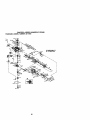
BELT INSTALLATION 1, Install new belt around engine pulley
first, then around transaxle pulley and
lastly into all the idler pulleys.
2. Check to be sure belt is positioned
correctly and is on proper side of all
belt keepers.
3. Engage the drive belt tension handle
and replace the retainer spring.
4. Reinstall mower.
Rotor-mL.__ C,utchPlate_.012"
TRANSAXLE MOTION CONTROL
LEVER NEUTRAL ADJUSTMENT
The motion control lever has been preset
at the factory and adjustment should not
be necessary.
1. Park Tractor on level surface. Stop
tractor by taming ignition key to "OFF"
position and engage parking brake.
2. Loosen the adjustment bolt in front of
the right rear wheel.
3. Move motion control lever to the
neutral position.
4. Tighten the adjustment bolt.
Slot 13)"_"'-i
Nylon_'
/ [
_
Brake
Rate
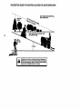
TO REPLACE MOTION DRIVE BELT
Park the tractor on level surface. Engage
parking brake. For ease of service there
is a belt installation guide decal on
bottom of left footrest.
1. Remove mower (See "TO REMOVE
MOWER" in this section of this
manual.)
BELT REMOVAL 2. Create slack in belt by removing
retainer spring from drive belt tension
handle.
3. Remove belt from all idler pulleys,
transexle pulley and then from engine
pulley.
Tension
Handle
EnginePulley
/_
Belt Keeper
TransaxlePulley
TRANSMISSION REMOVAL/REPLACEMENT
Should your transmission require
removal for service or replacement, it
should be purged after reinstallation and
before operating the tractor. See
"PURGE TRANSMISSION" in the
Operation section of this manual
TO ADJUST STEERING WHEEL ALIGNMENT
If steering wheel crossbars are not
horizontal (left to fight) when wheels are
positioned straight forward, remove
steering wheel and reassemble per
instructionsin the Assembly section of
this manual.
FRONT WHEEL TOE-IN ADJUSTMENT
Front wheel toe-in is required for proper
steering operation. Toe-in was set at the
factory and adjustment should not be
necessary. If parts in the front axle or
steering mechanism have been replaced
or damaged, check toe-in and adjust if
necessary.
26
TO CHECK TOE-IN 1. Position front wheels straight ahead.
2. Measure distance between wheels at
front and rear of tires (dimensions "A"
and "B").
• Front dimension "A" should be 1/8" to
1/4" tess than rear dimension "B".
NOTE: To seal tire punctures and prevent
flat tires due to slow leaks, tire sealant
may be purchased from your local parts
dealer. Tire sealant also prevents tire dry
rot and corrosion.
Washers
Retainin
TO ADJUST TOE-IN 1. Loosen jam nuts at adjustment
steevas on tie rod.
2. Adjust tie rod until dimension "A" is
1/8" to 1/4" less than dimension "B".
3. Tighten jam nuts securely.
FRONT WHEEL CAMBER
The front wheel camber is not adjustable
on your tractor. If damage has occurred to
affect the front wheel camber, contact
your nearest Sears or other qualified
service center.
Axle
_B_
Jam Nuts
TO REMOVE WHEEL FOR REPAIRS
FRONT WHEEL1. Block up axle securely.
2. Remove axle cover, retaining dng and
washers to allow wheel removal.
3. Repair tire and reassemble.
4. Replace washers and snap retaining
ring securely in axle groove.
5. Replace axle cover.
REAR WHEEL 1. Block rear axle securely.
2. Remove five (5) hub bolts to allow
wheel removal.
3. Repair fire and reassemble. Replace
and tighten hub bolts securely.
TO START ENGINE WITH A WEAK
BATTERY
_bCAUTION: Lead-acidbatteriesgenerate
explosivegasos. Keep sparks,flame and
smofdngmaterials away fiom batteries.
Alwayswear eye protectionwhen around
batteries.
Ifyour battery is too weak to startthe angine, it
should be recharged. (See "BA'I-I'ERY"in the
MAINTENANCE soc_on of _s manual).
If "jumper cablss" are used for emergeecy
starting,followthis procedure:
IMPORTANT: Yourtractoris equippedwi_ a
12 voltnegativegroundedsystem.The other
vehical mustalso be a 12 voltnegative
grounded system.Do not useyourtractor
battery to startothervehicles.
TO A'I-I'AC
H JUMPER CABLES 1. Connect each end of the RED cable to
the POSITIVE (+) terminal of each
battery, taking care not to short
against chassis.
2. Connect one end of the BLACK cable
to the NEGATIVE (-) terminal of lully
charged battery.
3. Connect the other end of the BLACK
cabte to good CHASSIS GROUND,
away from fuel tank and battery.
TO REMOVE CABLES, REVERSE ORDER 1. BLACK cable first from chassis and
then from the fully charged battery.
2. RED cable last from beth batteries.
27
REPLACING BA'I-rERY
_3AUTION:
Do not short battery
terminals by allowing a wrench or any
other object to contact both terminals at
the same time. Before connecting battery,
remove metal bracelets, wristwatch
bands, rings, etc.
Positiveterminal must be connected first
to prevent sparking from accidental
grounding.
1. Lift hood to raised position.
2. Remove terminal guard.
3. Disconnect BLACK battery cable then
RED battery cable and carefully
remove battery from tractor.
4. Install new battery with terminals in
same position as old battery.
5. Reinstall terminal guard.
6. Firstconnect RED battery cable to
positive (+) battery terminal with hex
bolt and keps nut as shown. Tighten
securely.
7. Connect SLACK grounding cable to
negative (-) battery terminal with
remaining hex bolt and keps nut.
_ghten securely
8. Close terminal access doors.
9. Close hood.
Terminal KepsN_
Access _.:_:.'...--_
•
E
_ _
Termff_al :' _
Guard_
d
=,.,,.....---....,_
Hex Bolt
_
_
Positive
(Red)
table
F FNegative
(Black)
_
Cable
TO ADJUST ATTACHMENT LIFT
SPRING
1. While holding spring bushing with
wrench, loosen jam nut.
• Turn adjustment bolt clockwise to
extend spring and reduce lift effort for
heavier attachments.
• Turn adjustment bolt counterclockwise
for lighter attachments.
2. Retighten jam nut against spring
bushing.
IMPORTANT: Do not adjust for maximum spring tension when using light
attachments such as a mower. Adjust lift
lever spring to aid in lifting attachment.
Do not overpower spring. When removing attachment, always adjust spring
tension to its lowest position.
Adjustment Bolt
I
Spdng
Jam Nut
TO REMOVE HOOD AND GRILL
ASSEMBLY
1. Raise hood.
2. Unsnap headlight wire connector.
3. Stand in front of tractor. Grasp hood
at sides, tilt toward engine and lift off
of tractor.
4. To replace, reverse above procedure.
TO REPLACE HEADLIGHT BULB
1. Raise hood.
2. Pull bulb holder out of the hole in the
backside of the grill.
3. Replace bulb in holder and push bulb
holder securely back into the hole in
the backside of the grill.
4. Close hood.
INTERLOCKS AND RELAYS
Loose or damaged wiring may cause your
tractorto run poorly,stop running, or
prevent it from starling.
• Check wiring. See electrical wiring
diagram in the Repair Pads section.
TO REPLACE FUSE
Replace with 30 amp automotive-type
plug-infuse. The fuse holder is located
behind the dash.
Headlight Wire
Connector
28
ENGINE
Maintenance, repair, or replacament of
the emission control devices and systems, which are being done at the
customers expense, may be performed
by any non-roed engine repair establishment or individual. Warranty repairs must
be performed by an authorized engine
manufacturer's service oufiet.
TO ADJUSTTHROTrLB CONTROL
CABLE
The throttle control has been preset at the
factory and adjustment should not be
necessary. Check adjustment as described below before loosening cable. It
adjustment is necessary, proceed as
follows:
1_ With engine not running, move throttle
control lever to fast position.
2. Chock that speed control lever is
against stop screw. If it is not, loosen
casing clamp screw and pull throttle
cable until lever is against screw.
Tighten clamp screw securely.
Idle Fuel Adjusting
Needle
Idle speed Adjusting
Throttle
Control
Cable
Screw
Clamp Screw
Choke Control Cable
TO ADJUST CHOKE CONTROL
The choke control has been preset at the
factory and adjustment should not be
necessary, check adjustment as described below before loosening cable. If
adjustment is necessary, proceed as
follows:
1. With engine not running, move choke
control (located on dash panel) to full
choke position.
2. Remove air cleaner cover, filter and
cartridge plate to expose carburetor
choke (See "AIR FILTER" in the
Maintenance section of this manual).
3. Choke should be closed, if it is not,
loosen casing clamp screw and move
choke cable until choke is completely
closed. Tighten casing clamp screw
securely.
4. Reassemble air cleaner.
Closed for Full
TO ADJUST CARBURETOR
The carburetor has been present at the
factory and adjustment should not be
necessary. However, minor adjustment
may be required to compensate for
differences in fuel, temperature, altitude
or load. If the carburetor does need
adjustment, proceed as follows:
In general, turning the adjusting needles
In (clockwise) decreases the supply of
fuel to the engine giving a leaner fuel/air
mixture. Turning the adjusting needles out
(counterclockwise) increases the supply
of fuel to the engine giving a richer fuel/
air mixture.
IMPORTANT: Damage to the needles
and the seats in carburetor may result if
screw is turned in too tight.
PRELIMINARY SETrlNG 1. Be sure you have a clean air filter, and
the throttle control cable is adjusted
propedy (see _'O ADJUST
THRO'I-I'LE CONTROL CABLE" in the
Service and Adjustments section of
this manual).
2. With engine off turn idle fuel adjusting
needle In (clockwise) closing it finger
tight and then turn out (counterclockwise) 1 tum.
FINAL SE'f-rlNG 1. Start engine and allow to warm for five
minutes. Make final adjustments with
engine running and shift/motion
control lever in neutral (N) position.
29
NOTE: The high idle is set at the factory
and cannot be adjusted.
2. Idle speed seffinn - With throttle
control lever in slow position, engine
should idle at 1200 RPM. if engine
idles too slow or fast, turn idle speed
adjusting screw in or out until correct
idle is attained.
3. Idle fuel peedle settina - With throttle
control lever in slow position, tum idle
fuel adjusting needle In (clockwise)
until engine speed decreases and
then fum out (osunterdookwise)
approximately 3/4 tum to obtain the
best low speed performance.
4. Recheck idle speed. Readjust if
necessary.
ACCELERATION TEST 5. Move throttle control lever from slow to
fast position. If engine hesitates or
dies, fum idte fuel adjusting needle
out (countemlockwise) 1/8 tum.
Repeat test and continue to adjust, if
necessary, until engine accelerates
smoothly.
High speed stop is factory adjusted. Do
not adjust-damage may result.
IMPORTANT: Never tamper with the
engine governor, which is factory set for
proper engine speed. Overspeeding the
engine above the factory high speed
setting can be dangerous. If you think the
engine-governed high speed needs
adjusting, contacta Sears o_other quaJified
servicecenter, which has proper equipment and experienos to make any
necessary adjustments.
3O
expedance indicates that alcohol
blended fuels (called gasohol or using
ethanol or methanol) can attract moisture
which leads to separation and formation
of acids dudng storage. Acidic gas can
CAUTION: Never store the tractor
damage the fuel system of and engine
with gasoline in the tank inside a building
while in storage.
where fumes may reach an open flame or
1. Drain the fuel tank.
spark, Allow the engine to cool before
2. Start the engine and let it run until the
fuel lines and carburetor are empty.
storing in any enclosure.
• Never usa engine or carburetor cleaner
TRACTOR
products in the fuel tank or permanent
Remove mower from tractor for w_nter
damage may occur.
store_e. When mower is to be stored for
• Use fresh fuel next season.
a penod of time, clean it thoroughly,
NOTE: Fuel stabilizer is an acceptable
remove all dirt, grease, leaves, etc, Store
alternative in minimizing the formation of
in a clean, dry area.
fuel gum deposits dudng storage. Add
1. Clean entire tractor (See "CLEANING"
stabilizer to gasoline in fuel tank or
in the Maintenance section of this
storage container. Always follow the mix
manual).
ratio found on stabilizer container. Run
2. Inspect and replace belts, if necessary
engine at least 10 minutes after adding
(See belt replacement instructions in
stabilizer to allow the stabilizer to reach
the Service and Adjustments sactk)n
the carburetor. Do not drain the gas tank
of this manual).
and carburetor if using fuel stabilizer.
3. Lubdceta as shown in the MainteENGINE OIL
nance section of this manual.
Drain oil (with engine warm) and repiece
4. Be sure that all nutS, bolts and screws
clean engine oil. (See "ENGINE" in
are securely fastened. Inspect moving with
the Maintenance section of this manuel).
pads for damage, breakage and wear.
CYLINDER(S)
Replace if necessary.
1. Remove spark plug(s).
5. Touch up all rusted or chipped paint
2. Pour one ounce of oil through spark
surfaces; sand lightly before painting.
plug hole(s) into cylinder(s).
BATTERY
3. Turn ignition key to =STAR'I" position
for a few seconds to distributeoil.
• Fully charge the battery for storage.
• After a pedod of time in storage, battery
4. Replace with new spark plug(s).
may require recharging.
OTHER
• To help prevent corrosion and power
• Do not store gasoline from one season
leakage dudng long pedods of storage,
to another.
b_ttary cabias should be disconnected
• Replace your gasoline can if your can
and battery cleaned thoroughly (see
starts to rust. Rust and/or dirt in your
"TO CLEAN BA'FrERY AND TERMINALS" in the Maintenance section of
gasoline will cause problems.
• If possible, store your tractor indoors
this manual).
and cover it to give protection from dust
• After cleaning, leave cables disconand dirt.
nected and place cablas where they
• Cover your tractor with a suifable
cennct come in contact v_th baltary
protective cover that does not retain
terminals.
moisture. Do not use plastic. Plastic
• If hettery is removed from tractor for
cannot breathe which allows condenstorage, do not store battery directly on
sation to form and will cause your
concrete or damp surfaces,
tractor to rust.
ENGINE
IMPORTANT: Never cover tractor while
FUELSYSTEM
engine and exhaust areas are stillwam_.
IMPORTANT: It is important to prevent
gum deposites from forming in essential
fuel system parts such as ca.d_retor, fuel
hose, or tank dudng storage. Also,
Immediately prepare your tractor for
storage at the end of the season or it the
tractor will not be used for 30 days or
more.
31
TROUBLESHOOTING
CHART
PROBLEM
_till not start
Hard to start
"nglnewlllnot
:urn over
CAUSE
1. Out of fuel.
2. Engine not "CHOKED"
properly.
3. Engine flooded.
CORRECTION
1. Fill fuel tank.
2. See "TO START ENGINE"
in Operation section.
3. Wait several minutes before
attempting to start.
4. Bad spark plug.
4, Replace spark plug.
5. Dirty air filter.
5, Clean/replace air filter.
6. Dirty fuel filter.
6, Replace fuel filter.
7. Water in fuel,
7, Drain fuel tank and carburetor. refill tank with fresh
gasoline and replace fuel
filter.
8. Loose or damaged wiring.
8. Check all wiring.
i9. Carburetor out of adjustment. 9. See "To Adjust Carburetor"
in Service Adjustments
section,
10.Contact a Sears or other
10.Engine valves out of
adjustment.
qualified service center.
11. Extreme Cold Conditions
11. See "To start engine" in
operation section.
1.
2.
3.
4.
5.
Dirty air filter.
Bad spark plug.
Weak or dead battery,
Dirty fuel filter.
Stale or dirty fuel,
Clean/replace air filter.
Replace spark plug.
Recharge or replace battery.
Replace fuel filter.
Drain fuel tank and refill with
fresh gasoline.
6. Loose or damaged widng.
6. Check all wiring.
7. Carburetor out of adjustment, 7. See "To Adjust Carburetor" ir
Service Adjustments
section.
8. Contact a Sears or other
8. Engine valves out of
adjustment.
qualified service center.
1. Brake pedal not
depressed
2. Attachment clutch is
engaged.
3. Weak or dead battery.
4. Blown fuse.
5. Corroded battery terminals.
6. Loose or damaged wiring.
7. Faulty ignition switch.
1. Depress brake pedal.
9. Faultyoperatorpresence
switch(es).
2. Disengage attachment
clutch,
3. Recharge or replace battery.
4. Replace fuse.
5. Clean battery terminals.
6. Check all wiring.
7. Check/replace ignition
switch.
8. Check/replace solenoid or
starter.
9. Contact a Sears or other
qualified service center.
1.
2.
3.
4.
1.
2.
3.
4,
8. Faulty solenoid or starter.
Engine clicks but
#111not start
1.
2.
3.
4.
5.
Weak or dead battery.
Corroded battery terminals.
Loose or damaged wiring.
Faulty solenoid or starter,
Recharge or replace battery.
Clean battery terminals.
Check all wiring.
Check/replace solenoid or
starter.
TROUBLESHOOTING
CHART
PROBLEM
CAUSE
Lo_power
1. Cuttingtoo
m_hgraas/too
2.
3.
4.
5.
6.
fast.
Throttle in =CHOKE"
position.
Build-up of grass, leaves
and trash under mower.
Dirty air filter.
Low oil level/dirty oil.
Faulty spark plug.
7. Dirty fuel filter.
8. Stale or dirty fuel.
9. Water in fuel.
10.Spark plug wire loose.
11. Dirty engine air screen/fins.
12.Dirty/clogged muffler.
13.Loose or damaged widng.
14.Carburetor out of
adjustment.
15.Engine valves out of
adjustment.
Excessive
vibration
1. Worn, bent or loose blade.
2. Bent blade mandrel.
3. Loose/damaged part(s).
CORRECTION
1. Set in =Higher Cut" position/
reduce speed.
2. Adjust throttle control.
3. Clean underside of mower
housing.
4. Clean/replace air filter.
5. Check oil level/change oil.
6. Clean and regap or change
spark plug.
7. Replace fuel filter.
8. Drain fuel tank and refill
with fresh gasoline.
9. Drain fuel tank and
carburetor, refill tank with
fresh gasoline and replace
fuel filter.
10. Connect and tighten spark
plug wire.
11.Clean engine air screen/
fins.
12.Clean/replace muffler.
13.Check all widng.
14.See rio Adjust Carburetor"
in Service Adjustments
section.
15.Contact a Sears or other
qualified service center.
1. Replace blade.
"lighten blade belt.
2. Replace blade mandrel.
3. Tighten loose part(s).
Replace damaged pads.
Engine continues
to run when
operator leaves
seat with
attachment
clutch engaged
1. Faulty operator-safety
presence control system.
1. Check widng, switches and
connections. If not correcte_
contact a Sears or other
qualified service center.
Poor cut- uneven
1. Worn, bent or loose blade.
1. Replace blede. Tighten
blade bolt.
2. Level mower deck.
3. Clean underside of mower
housing.
4. Replace blade mandrel.
5. Clean around mandrels to
open vent holes.
2. Mower deck not level.
3. Buildup of grass, leaves,
and trash under mower.
4. Bent blade mandrel.
5. Clogged mower deck vent
from build-up of grass,
leaves, and trash around
mandrels.
33
TROUBLESHOOTING CHART
CAUSE
PROBLEM
_ower blades will
rtot rotate
Poor grass
discharge
Headlight(s)not
working
(if so equipped)
CORRECTION
1. Obstruction in clutch
mechanism.
2. Worn/damaged mower
drive belt.
3. Frozen idler pulley.
4. Frozen blade mandrel.
iEnglne "backfires"
whenturnlng
ienglne
"OFF"
3. Replace idler pulley.
4. Replace blade mandrel.
1. Place throttle control in
=FAST" position,
2. Travel speed too fast.
2. Shift to slower speed.
3. Wet grass.
3. Allow grass to dry before
mowing.
4. Mowerdecknot level.
4. Level mower deck.
5. Low/uneventire air pressure,_
5. Check tires for proper air
pressure.
6. Worn, bent or loose blade.
6. Replace/sharpen blade.
I
Tighten blade bolt.
7. Buildup of grass, leaves and I 7. Clean underside of mower
trash under mower.
housing.
8. Mower drive belt worn.
8. Replace mower drive belt.
j9. Blades improperly installed. 9. Reinstall blades sharp edge
down.
10.Improper blades used.
10. Replace with blades listed
in this manual.
11 .Clean around mandrels to
11.Clogged mower deck vent
holes from buildup of
open vent holes.
grass, leaves, and trash
around mandrels.
1.
2.
3.
4.
Switch is"OFF-'.
Bulb(s) or lamp(s) burned out.
Faulty light switch.
Loose or damaged wiring.
1. Bad battery cell(s).
2. Poor cable connections.
3. Faulty regulator
(if so equipped).
4. Faulty alfarnaton
Loss of drive
Replace mower drive belt.
1. Engine speed too slow.
5. Blown fuse.
Battery will not
charge
Remove obstruction.
1,
2.
3.
4.
Turn switch =ON'.
Replace bulb(s) or lamp(s).
Check]replace light switch.
Check wiring and connections.
5. Replace fuse.
1. Replace battery.
2. Check]clean all connections.
3. Replace regulator.
4. Replace alternator.
1. Freewheel control in
"disengaged" position.
2. Motion drive belt wom,
damaged, or broken.
3. Air trapped in transmission
during shipment or
servicing.
1. Place freewheel control in
"engaged" position,
2. Replace motion drive belt.
1, Engine throttle control not
set at =SLOW"
position for 30 seconds
before stopping engine,
1. Move throttle control to
=SLOW" position and allow
to idle for 30 seconds before
stopping engine.
34
3. Purge transmission.
TRACTOR - MODEL NU_t6_-.R9_t7.275000
$cHEMATtC
TRACTOR-
MODEL NUMBER 917.275000
ELECTRICAL
I0
29
/
/
36
TRACTOR - MODEL NUMBER 917.275000
ELECTRICAL
KEY
NO.
1
2
8
10
11
12
16
21
22
25
26
27
28
29
30
33
40
42
45
50
52
79
81
PART
NO.
144927
74760412
7603J
145211
150109
145769
153664
166184
4152J
150755
1088_4X
73510400
170697
160784
175566
140403
17G_38
154336
1228_2X
174652
141940
163996
109748)(
DESCRIPTION
Battery
Bolt Hex Head 1/4-20 x 3/4
Tray, BattePJ
Bolt I/4-20 x 7.5 Zinc
Hald down Battery Dash Mount
Nut Push Nylon 1/4"
Switch Intedock Push-in
Harness S_cket Light W/4152J
Bulb Light
Cable, Batte_
Fuse
Nut Keps Hex 1/4-20 Unc
Cable, Ground
Switch, Plunger
Switch, Ign
Key, Ignition
Harness Ign.
Cover, Terminal
Ammeter
SwitCh, PTO
Protection Wire Loop
Bulbholder Asm Incandescent SV
Relay Asm,
NOTE: AJIcomponent dimensions given in U. S.
inches I inch = 25.4 mrn
37
TRACTOR - MODEL NUMBER 917.275000
CHASSIS AND ENCLOSURES
37
21
38
TRACTOR
- MODEL
NUMBER
917.275000
CHASSIS
ANDENCLOSURES
KEY PART
NO, NO.
1
175465
2
175282
4
73800700
5
163976X428
6
1578_2
7
17720408
8
145166
14
175259X558
16
121794X
17
17060612
18
174515X&58
19
19131312
20
S'RTo23710
21
STD541437
24
145243X558
28
145244X558
30
145_o2
31
161419
32
161327
33
161326
34
177018
35
19111116
36
S'R3.522507
37
167287X558
39
175278
42
$11T533710
43
136939
44
136940
45
154913
47
174906Q8
50
175476
56
154914
58
175315
68
1749C508
84
142992
86
74760716
91
175464
g9
177143
102 STD(_4C03
122
161464
130
164863
138
163975X428
139
171873
140
1638O6
141
163805
142
161897
144
161900
148
1646r_5
150
161237
152
177956
153 160568
156 1706(_12
157
161840
158 17_
159 17000612
DESCRIPTION
Rail, Frame RH
Drawt_ar, Gt
Nut, Lock Hex 7116 Unc
Dash YTGT 2 Cyl
Dash, Lower Vgt One Piece
Screw, Thd CUt 1/4-20 x 1/2
Support, Battery
Hood AXm
Cover, Access
S_'_nv 3/8-16 X .75
Grille
Washer 13/32x15/16x12 Ga.
Bolt, FInHex 3/6-16xt
NutCrowntock 3/8-16Unc
Footrest, RH
Footrest. LH
Saddle, Hydro
Brace, Supt 1-pc VGT
Bracket, Pivot Chassis Lh
Bracket, Pivot Chassis Rh
Plate Asm Engine
Washer 11/32xl 1/16x16 Gtt.
Bolt, Fin Hex 5/16-18 x 3/4
Fender Pnt
Bracket, Axle Front
Bolt. Carriage 3/8-16 x 1
Bracket, Spnsn Front Lh
Bracket, Spnsn Front Rh
Bracket Asm., Susp Ches.Rh
Screw Thdrol. 3/8-16 x 1/2
Bracket, Chassis Front
Bracket Asm., Susp Ches. Lh
Bracket Asm., Fender
Screw Thdrol. 5/16-16 x 1/2
Stop, Over Center Mower
Bait Fin Hex 7/16-14 UNC x 1
Rail. Frame Lh
Rod By Pass
Retainer, Spring
Screw Hex Wshd 6-18 x 7/8
Screw Hwhd Hi*Lo #19-16x5/4
CupHolder
Bolt Shoulder 5/16-18 TT
Magnet YTGT
Stalker Prate YrGT
Bracket Dash Rh
Bracket Dash Lh
Extrusion Bumpers
Duct Hest Hood
Shield Browning
Lens Asm Headlight Bar
So'ew 5/16-18 x 3/4
Lens Bar
Screw Thdro_ 5/6-16 x 1/2
Screw 3/8-16 x .75
NOTE: NI component dimensions given in U. S.
inches 1 inch = 25.4 mm
39
TRACTOR
- MODEL
NUMBER
917.275000
GROUND
DRIVE
M
33
144
40
TRACTOR - MODEL NUMBER 917.275000
GROUND DRIVE
KEY
NO.
1
2
6
7
9
20
22
23
29
33
34
36
36
37
38
39
40
41
42
46
48
50
52
53
55
56
58
61
64
65
58
69
70
71
73
74
77
89
PART
NO.
.....
DESCRIPTION
Tmnsaxle Hydro C-ear
331-3000 (See Breakdown)
9396E
Key 1/4 x 1/4 x 2
STKTo61210 Pin, Coher
140507
Wheel, Hub Assembly
140080
Bolt, Hub
73940800
Nut
178391
Lever Asm Shilt Lower
130564
Kncb
176600
Brake, Rod
1_
RingE
71673
Cap, Paridng Broke
137648
Rod, Parking Brake
149412
Spdng, Drive Ground
121749X
Washer 25/32 x 1-1/4 x 16 Ga.
1500_5
Nyltner
74321016
Screw, Fin. #10-24xl
178575
Actuator, Interlock Sw_tch
73931 _30
Nut Centerlock 10-24 Uric
8983R
Cover, Pedal
145170
Retainer, Spr_ng
72110614
Bolt, RDHD 3/8-16 x 1-3/4
Gr. 5
131494
Pullay. Idler, Flat
127783
Pulley, Idler. Grooved
207J
Washer, Hazdened
10b'7C6X
Bearing, Idlar
161597
V-Befl
74760724
Bolt Fin Hex 7/1 0-14 x 1-1/2
143995
Pulley, Tnmsaxle
176601
Shaft, Clutch/Brake Pedal
67609
Bolt, Shoulder
s'rD571812
Pin, Roll
123800X
Washer
164892X428 ConsoleAutomaticYT/GT
151179
plate Consola Shift
74490548
Bolt Hex Flghd 5/10-18 x 3
Gd3
142432
Screw Hex Wsh, HFLo
1/4-1/2
74760716
Bolt Fin Hex 7116-14 x I
73680700
Nut Crownlock 7/16-14 Unc
KEY
NO.
94
89
106
107
106
PART
NO.
133_35
141004
142918
154739
142917
111
112
114
117
120
121
122
156240
156104
_
73900600
17060612
175611
721052(30
123
124
125
126
176602
165492
166880
166002
127
128
129
130
131
132
133
135
137
13_
142
143
144
145
146
147
148
149
151
152
177362
176624
178588
19131016
76020312
175467
1754_8
177364
168514
137(7H
175469
17060512
160849
163168
140462
141322
1706_616
19131410
74760512
1787_
DESCRIPTION
Faslaner Chdstmas Tree
Bracket Shift
O-RingAsm Hydro Gear
LineFuelHydrot5"VGT
Cap Asm Vent Hydro Gear
70109
Spacer Sh_ftLever VGTH
Washer Nylon High Temp
Nut Lock Hx W/Ins 5/16-18 Uric
Nut, Lock Fig. 3/0-16
Screw 3/8-16 x .75
Bracket Sttap Torque
BoltRDHDSQ
5/16-18unc x 2-1/2
ROd Shift
BoltShoulderS/16-18x
.561
Screw 5/16-18 x 5/8
WasherSRRTDS/161Ox1.0x
.125
Unk Control Clutch
Spring Drk.e GRND
Bracket Asm Idlar Tet_sioning
Washer 13/32 x 5/8 x 16 Ga
Pin Cotter 3i32 x 3/4
Bracket Mtg Hydro3.500 LH VGT
Bracket Mtg Hydro 3500 RH VGT
Unk Asm Control Hydro 35_)
Nut Lock 5/16-18 NC Tnd
Washer Thrust 5/8 x 1.10 x 1/32
Strap TOKlUe HG-3500
Screw Tndrol 5/16-18 x 3/4
Washer Spacer Axle HG-3000
WasherAxreFlangeHG-3000
Fen 7" Hydro
Washer
Screw 3/8-16 x 1.0
Washer 13/32 x 7/8 x 10 Ga
Bolt Fin Hex 5/16-18unc x 7/8
Boft Hex 5/10-18 x 1
NOTE: All component dimensions given in U. S.
inches 1 inch = 25.4 mm
41
TRACTOR - MODEL NUMBER 917.275000
STEERING
23
42
TRACTOR-
MODEL NUMBER 917.275000
STEERING
KEY PART
NO. NO.
DESCRIPTION
I
2
3
4
5
6
7
8
9
10
11
12
13
14
15
16
17
18
1g
20
21
oo
23
25
28
27
28
29
31
_o
33
34
35
36
37
38
39
40
41
42
44
45
46
47
48
49
50
Wheel,Steering
Axle Asm., Front
Fitting, Grease
Splndta Asm, I.H
Spindle Asm. RH
Beadng, Race Thrust Harden
Washer 25_J2 x 1-5/8 x 16 Ga.
Ring. Klip #T5304-75
Cap, Spindle
Bolt, Fin Hex .5/8-11 x 2-3/4
Spacer Bearing Axle Front
Nut, Lock Flange 5/8-11 Unc
Washer 25/32 x 1-1/4 x Ift Ga.
wE_sher, LockHvyHIclSpr
3/8
Nut, Lock Center 3/6-24 UNF
Shaft Asrn., Steedng
Rod Asm., Tie Bell J Bell Vgt (Inc, Key No, 36-40)
Draglink, Ball Joint So!_l Vgt
Support Asm., Steedng vgt
Boot, Steering
Adapter, Wheel Steering
Bushing, Strg. BJk
Screw
Bolt, Fin Hex 3/6-16 x 1Gr. 5
Cap, Wheel Steedng
Bearing, Col. Strg.
Screw, 3/8-16 x 3/4
Bearing, Flange
Bushlag, Nyliner Snap
Washer 11/32 x 1 x 10 Ga.
Washer. LockHvyHIclSpr
5/16
Bolt Fin Hex 5/16-18uric x 3/4
Gear, Sentor Steedng
T_e ROd
Jam Nut RH Thread
Joint Asm. BaH RH Thread
Jam Nut LH Threap
Joint Asm. Ball LH Thread
Bracket Switch Interlock VGT 97
Screw Thdrol 5/16-18 x 1/2 Tyt
Extension, Steedng
Washer 13/32 x 1-1/20 x 11 Ga.
Spacer
Bracket Asm idler Stationary
Screw 3/8-16 x .75
Puney Idler Flat
Nut Lo<:kFig 5/6-16 UNC
159944X428
178557
6&55M
181849
161848
6266H
121748X
120(XX]29
1212_.X
74781044
136518
73901000
121749X
S'i_551137
STD541537
145103
137347
175572
156011
163887X428
159945
155106
1529_7
74780616
159946X428
3366R
17000612
104239x
138136
19t11610
STD551131
74780512
138059
137156
73360600
109850X
73700600
10_StX
1552A6
17490508
160135X428
191_411
178_91
177863
17060612
131494
73900600
NOTE: All component dimensions given in U. S.
inches 1 inch = 25.4 mm
43
TRACTOR - MODEL NUMBER 917.275000
ENGINE
69
KEY PART
NO. NO.
1
......
2
8
9
10
11
12
15
16
17
18
20
21
22
24
25
28
27
28
29
31
149723
121361X
177748
175288
170(To6
143996
151346
10S_27X
1060_2X
161493
177328X428
164863
175441X428
STD551237
739206(_
3645J
13_77
7834R
137180
145006
DESCRIPTION
Engine (See Breakdown)
Kohler Model NO.CV674-75544
Muffler
Pulley V-Idler
Keepe_ Asm, Beit Engine
Bushing
Clutch Elechic
Puney Engine VGT Elect Crutch
Tank Fue_ Rear 3.50 YtiGt 96
Pad Spacer
Pad Spacer
Cap Asm Fuel W/Gauge
Control'rnrottle
Screw hwhd Hi-Lo #13-16x3/4
ControlCheke
Washer Ext Tooth 3/8
Nut Keps 3/8 - 24 UNF
Bu6hing
Stem Tank Fuel
Fuel Une
Spark Attester Kit
Clip
KEY PART
NO. NO.
35
37
39
40
41
1001G500
123487X
17490636
174g_664
126197X
42
43
47
1_2
_)
70
71
74
80
81
82
83
84
$3_651143
173gG7
175287
146629
24-O41-(_
175545
175546
162295
M73030800
148456
148315
171877
17060624
DESCRIPTION
Washer Split
ClampHose
Screw'IT 3/8-16 x 2-1/4 UNC
Screw "i'r 3/8-16 x 4 UNC
Washer 1-1/20D x15/32 ID x
,250
WasherLock7/16
9_t Hex 7/16 * 20 X 4 x Gr 5-1.5
Spewer Engine
Shiekt Heat Muffler
Gasket
Tube Exhaust LH
Tube Exhaust RH
EYoow Street Brass
NutFlange
Tube Drain Oil Easy
Plug Drain Oil Easy
Bolt 5/16-18uflc x 3/4
Screw Thdrol 3/8-16 x 1-1/2
NOTE: NJ component dimensions givefl In U. S,
inches t inch = 25.4 mm
44
TRACTOR
- MODEL
NUMBER
917.275000
SEAT
ASSEMBLY
i
i
22
21
KEY
NO.
1
2
3
4
5
6
7
8
10
12
13
PART
NO.
140124
14_651
140675
127018X
145006
STD541437
124181X
171877
174894
121246X
121248X
DESCRIPTION
Seat
Bracket. Pivot Seat
Strap, Fender
Bolt, Shoulder 5/16-18 x .6,?.
Clip, Push In, Hinged
Nut, Crownlock 3/8-16Unc
Spring, Seat Cprsn
Bolt5/16-18Uncx3/4 wlSems
Pan, Seat
Bracket, Mounting Switch
Bushing, Smzp
KEY
NO.
PART
NO.
DESCRIPTION
14
15
16
17
18
19
20
21
22
72060412
12_;249X
123740X
123976X
19171912
166369
124238X
171852
STD541431
Bolt, Carriage 114-20 X 1-1/2
Spacer. Split
Spdng, Crxsn
Nut, Lock 1/4 Lge Fig Gr. 5
Washer 17/32xl-3/16x12 Ga.
Knob, Seat
Cap, Spring Seat
Bolt, Shoulder 5/16-18
Nut, Crownlock 5/16-18Unc
NOTE: All component dimensions g_ven in U. S.
inchos 1 inch ==25.4 mm
45
TRACTOR - MODEL NUMBER 917.275000
DECALS
18
17
17
15
15
12
8
11
KEY
NO.
1
2
PART
NO.
164094
149516
3
4
5
6
7
8
9
10
11
12
171702
171703
14O837
133644
177416
164884
1632O4
156439
177781
177554
DESCRIPTION
DecaIDash
Decat Satterj ONGR/PSN
ENQASm
Decal Hood RH Craftsman
Decal Hood LH Craftsman
Decal Brake Parking SaddLe
Decal Maintenance
Decal Engine
Decal Bk)wer Hsng Kohl
Decal, Fender Craftsman
Decsl Fender Danger
DecalFTREST
Decal V-Belt Dr Sch
WHEELS ANDTIRES
KEY
NO.
13
15
17
18
19
22
23
*--
PART
NO.
177543
177415
177375
164065
138047
166960
1062(_X
157199X428
138311
---
179082
17g083
DESCRIPTION
Decal Replacement
Decal Hood Side Phi
0ecai Dash Panel
Decal I_sed Strg
Decal Batted/
Decal Dmwt_'CNTRL
Reflectro, T_llight
Pad Footrest
Oecal Handle Lft Height
Adjust (Lift Handle
Owner's Manua, Eng sh
Ownel's Manual, Spanish
KEY
NO.
PART
NO.
DESCRIPTION
1
2
3
4
5
6
7
8
9
10
11
12
--
5919_
65139
I06228X427
8134H
106230X
27811
904CH
104757X428
1(_o588x
7154J
106_7X427
6_6M
144334
Cad Valve _re
Stem Valve
RimAsm Front
Tube, Front (Service Item Only)
l_re, Front
Fittin_ Gres_se(Front Wheel Only)
Beadng Ftange(Front Wheel Only)
Cap Axte (Front Wheel Only)
Tn Rear
Tube Rear (Service Ilem Onty)
RimAsm Rear
Fdltng Gresse
Sealant, Tire ( I0 oz. Tube)
NOTE: All component dlmenslor.s given in U. S.
inches 1 inch = 25.4 mm
46
TRACTOR-MODEL
NUMBER
917.275000
LIFT ASSEMBLY
40
42
43
3573
34
38
J
7
7
31
9
10
39
16
15
76
4_829
23
KEY
NO.
PART
NO.
I
2
3
4
5
6
7
8
9
10
11
12
13
14
15
16
18
"_9
20
21
22
23
24
121006X
177535
159189
120000_2
19292016
Til I0624
175830
175831
122364X
2876H
146704
163552
13_668
169665
STD541437
674A2.47
143_63
ST_651_'/
53_8J
STC623710
127218
S]_:4006
733508(X)
75
DESCRIPTION
Rod Asm., Lever
She_ Asrn., L_ V_
Lever Asrn., Lift Rh
E-Ring Truar¢ #5133-87
Washer 29/32 x I-1/4 x 16 Ga.
Butt, _n Hex 3/8-'_6 x I-I/2
Gdp, Handle Ruted
Button, Plunger
Plunger, Button
Sp_
2-I/8'
Link Lift
Retainer, Spring
Arm, Susgension Vgt
Nut, Crownleck 3/8-16Unc
Spring Asrn., Assist Lift
Bracket, Spring Assist
Washer 13,_2x1_16x16Ga.
Bolt, Adjust SPnng Assist
Bolt, FinHex 3/8-t6xl
Un_ Front
Retainer, Spring
Nut, Jam Hex I/2.13 Unc
KEY
NO.
PART
NO.
26
29
30
31
32
33
34
36
38
39
40
41
42
43
70
72
73
75
76
78
73680800
Nut Crownlock 1/2-13 Unc
_50233
Tmnnion, lnfin He_ht
11060"/X
Nut, Special
$1_5_tG37
Washer 13/32x5_x16Ga.
137150
Spdng, Compression Inf Hgt
$11To60907 p_,Cotter
3/32xlt2
137167
Rod, Adj Lift
138057
Knob, Inf 3/8-14 Uric
155097
Pointer, Height Indicator
123935X
p_,Ho_
174_;16
Soew Hex Wsh 5/16-18 x 1
73540600
NUt, Crownlock 3/8-24
19112410
Washer 11/32 x 1-1/2 x 10 Ga.
123934X
S¢_e, tnd_tor Height
145212
Nut Hex Flange Lock
110452)(
Nut Push PhOS & Oil
73350600
Nut Hex Jan13/8-16 UNC
175806
PkL1eAsm F_onl
175560
pin Flange
175689
Trunnion
DESCRIPTION
NOTE: Artcomponentdk_ensions
givenin U. S.
inches1 inch= 25.4 mm
47
TRACTOR
- MODEL
NUMBER
917.275000
TRANSAXLE-MODEL
NUMBER
331-3000
48
TRACTOR - MODEL NUMBER 917.275000
TRANSAXLE-MODEL NUMBER 331-3000
KEY PART
NO. NO.
DESCRIPTION
1
2
3
4
5
6
7
8
9
10
11
12
13
14
15
21
24
25
26
27
28
29
30
31
32
33
34
35
36
37
38
39
40
41
42
43
44
48
50
51
52
53
54
56
56
57
58
59
60
61
62
63
64
65
66
67
68
69
70
71
73
Main Housiog Assembly
R.H. Housing Assemb;y
Center Section Assembly
Spaz_r
Seat-Up
Wire Retaining Ring
Retaining Ring
Ball Bearing
Cradle Bearing
V_iabld Swashplet e
Thrust Beadng 30 X 52 X 13
Input Shaft
Block 11_rustWasher
Arm - Trunnion
10cc Cylinder Block Assembly
21cc Cylinder Block Assembly
Output (Motor) Shaft
Thrust Bearing 42 X 68 X 16
ControlArrn
Spacer
161 Pinion Gear
Capscrew, M6 X 1-22
Sldt Guide
Trunnion Arm
Trunnion Bushing
Lip Seal
Arm Return
Arm Actueting
5/16-24 Stud
Puck, Friction
Bypass Rate
Bypass Actuator
Lip_at
Bypass Arm
RetaioingRing
Pin
Screw
Puck
Sc_ew-SetfTapplng
LowerCover
Gerotor Assembly
O-Ring
Gerotor Cover
Fi]ter
Charge Manifold
Retainer, Motor Searing
Pin, Carder
15t Planet Gear
71Spur Gear
21t Sun Gear
Plenet ThnJst Plete
511 Ring Gear
Planet aPj Canter
Miter Gear, Diff. (splined)
Miter Gear, Diff.
Shaft, DifferenBal
Diff. Thrust P!ate
Flange Bea_ng
Washer
Washer
Hex Jam NUt. 5iff-18
161122
178317
169522
161125
142932
142928
142933
1429_4
169523
169524
150771
161126
142978
142977
196(_0
169525
161127
169526
161128
161129
161130
169527
142941
161132
161133
142940
178318
178319
169528
142967
150787
169529
142945
142952
142953
142_56
150797
178_0
178343
16_o30
16_o31
144581
161139
178321
169533
161142
161143
161144
161145
161146
161147
161148
161149
161150
161151
161152
161153
16_34
161154
161156
161156
KEY PART
NO. NO.
74
75
76
77
79
80
81
82
83
84
85
87
88
89
g0
91
9_
93
94
_6
96
97
106
106
110
111
116
117
120
121
122
124
125
126
127
128
129
130
131
132
134
136
137
138
139
16S535
161157
161153
142884
178322
161159
161160
161161
161162
161163
161164
178323
178324
178325
178326
169536
178.327
142969
142980
169537
169538
150798
161166
178328
142918
142917
169539
161168
142883
169540
178329
178330
142887
161172
161173
142885
142886
161174
142882
169544
178331
178332
178333
178334
161176
141
144
145
146
151
152
153
155
157
180
20_
900
178335
16_,345
169546
169547
161181
178336
142914
178337
16.9548
16_349
178338
166773
DESCRIPTION
Ball Brg 6205-1
Seal 1"Id X 2.0472" X 0.375"
Shaft, Axle
Washer
Gasket Material
Torx Head Serew, 5/16-18
Needle Searing (Sce 1412)
Wash_2
Retaining Ring
Up Seal (0.875i. D.X1.3O.D.XO.25
Brake Disk
Wash_
Screw 5/16-24
Bearing
Spacer
Odng, 0.070 X 0.239
Sccew
Spring, FdcUon Pack
Spacer, Friction Pack
Hex Lock Nut 5/16-24
Steeve Bearing
Oil
Spacer, Trunnion
Rug
Rtting-O Ring Ass'y
Cap Vent Ass'y
Retaining Ring
Std Hdls Pin
Puck, Brake
Rid Neck Bolt, 2"
Brake Yoke
Arm, Brake
Pins, Brake
Lockwasher, 1/4"
Nut. 114-20
Nut, Castle
Cofter Pin
Spacer
Puck Plate
Rib Neck Bolt, 3" 1
Spring
Spring Ext en..sion
PIOSpring
Bolt Self Tapplng
Washer, 7/8od X 0.265id X 0.125
Thk
Sp,ltng Brake
O Ring, 2.864 Id X 0.070 Thk
Spring. Relief
Ball, 7/16
Comp. Spdug, Brake Anti- Drag
Brake Pull Rod
Plug. Stretght Thcead
Kit Fan
Serew O-Ring
Manifold Kit
Kit Seal
Trans_de, complete
NOTE: All component dimensions given In U.S. inches
1 inch = 25.4 mm
49
TRACTOR
- MODEL
NUMBER
917.275000
KOHLER
ENGINE-MODEL
NUMBER
CV674,
TYPENUMBER
75544
CYLINDER
HEAD,
VALVE
AND
BREATHER
I
_1|
I
11
"
/t
Q
/
k___
Io
.-8t7
o--.-$
5O
TRACTOR - MODEL NUMBER 917.275000
KOHLERENGINE-MODEL NUMBER CV674,TYPE NUMBER 75544
HEAD/VALVE/BREATHER
CRANKCASE
KEY
NO.
PART
NO.
KEY
NO.
1
24-033-03-S
2
3
4
24-041-23-S
24-096-59-S
M-645020-S
5
6
7
X-75-23-S
25-351-01-S
24-758-66-S
8
9
10
11
12
13
24-411-05-S
24-041-40-S
24-318-70-S
25-186-01-S
24-599-01-S
M-640034-S
14
24-072-09-S
18
16
17
24 468 16-S
24 100 10-S
24-755-74-S
18
19
20
21
23
24
25
26
27
28
29
24-153-16-S
24-086-32-S
24-445-01-S
24-016-01-S
24-016-02-S
24-017-01-S
24-017-02-S
24-032-05-S
238011-S
24-089-02-S
12-173-01-S
12-755-03-S
24-318-67-S
24-755-76-S
30
31
25-313-02-S
24-755-57-S
32
M-545016-S
33
34
35
36
37
38
39
24-445-02-S
24-126-44-S
24-112-12-S
24-294-06-S
24-326-13-S
24-326-14-S
25-237-14-S
22
DESCRIPTION
Kit, breather cover w/gasket
Includes 2, 3
_asket, breaker
Cover, breather
Screw, he)(. flange
M6x1.0x20 (4)
Plug, allen hd. I/8"
Lifter,valve (4)
Kit, valve train (Includes 8,
11, 12)
Red, push (4)
Gasket, cylinder head (2)
Head assembly, #2 cylinder
Arm, rocker (4)
Pivot, rockerarm (4)
Screw, hex. flange
M6xl.0x34 (4)
Stud, cylinder head
M8x1.25x20, M10x1.gx33,
105 mm long (8)
Washer, flat 8 mm (8)
Nut, bex. flange Mgx1.28(2)
Kit, valve cover - plain
(thcludes 18, 19)
O-Ring
Screw, shoulder (4)
Strap, liffing
Valve, exhaust (Std.) (2)
Valve, exhaust (.25)(2)
Valve, intake (Std.) (2)
Valve, intake (.25) (2)
Seal, valve stem (2)
Retainer, sprthg (4)
Spdng, valve (4)
Cap, valve spring(4)
Kit, retainer (4)
Head assembly, #1 cylinder
Kit, valve cover - breather
(Incl.18, 19, 30)
Grommet, rubber
Kit, breather separator
(Includes 30, 32-35)
Screw, has. flange
M5x0.8x16 (2)
Strap, breather
Bracket, breather separator
Spacer
Fitting
Hose, breather
Hose, breather
Clamp, hose (2)
PART
NO.
DESCRIPTION
24-032-01-S
Seal, oil fro_t
Crankcase
24-294-13-S
24-388-13-S
24-067-13-S
24-067-14-S
24-874-09-S
Pin,
Connectin
10
11
12
24-874-10-S
24-874-11-S
24-874-15-S
24-108-08-S
24-108-09-S
24-108-10-S
24-018-01-S
12-422-09-S
12-422-13-S
12-422-07-S
12-422-08-S
12-422-10-S
12-422-11-S
12-422-12-S
24-012-10-S
52-139-09-S
M-545010-S
13
14
15
16
17
18
24-018-04-S
24-402-05-S
12-153-01-S
24-126-19-S
12-123-04-S
M-545016-S
19
20
12-153-02-S
24-038-04-S
21
22
23
24
25
26
27
24-755-46-S
12-153-03-S
24-018-09-S
M-931010-S
28-032-09-S
24-468-15-S
24-144-33-S
7
8
9
Shin
Shim, camshaft
Shim, camshaft
Shim, camshaft q
Shlm, camshaft
Shim, camshaft A.R.
Sh_m,camshaft IA.R.I
Camshaft
Plug, cup
Screw, hex. flange
MSx0.gxl0 (2)
Retainer, reed (2)
Reed, breather 2
O-Bing,
lower
el} tube
Bracket, oil fill tube
Tube, oil fill
Screw, bex. flange
M5x0.8x16
O-Ring, upper oil fill tube
Dipsflck assembly (Includes
21, 22)
Kit, oil fill cap (Includes22)
O-Ring, di tick
Ring, retanlnlnPSelr
Washer, nylon (top)
Seal, governorcross shaft
Washer (bottom)
Shaft, governor cross
NOTE: All componentdimensionsgiven in U.S.
inches 1 inch = 28.4 mm
51
TRACTOR
- MODEL
NUMBER
917.275000
KOHLER
ENGINE-MODEL
NUMBER
CV674,
TYPENUMBER
75544
52
TRACTOR - MODEL NUMBER 917.275000
KOHLER ENGINE-MODEL NUMBER CV674, TYPE NUMBER 75544
BLOWER
HOUSING
S BAFFLES
IGNITION/CHARG]NG
KEY
NO.
pANT
NO.
KEY PANT
NO. NO.
Kit, grass screen
"t
ll_'_
2
t
54-755-15-S
2
M-403025oS Screw, hex. cap M4x0.7x25
3
4
3
4
5
6
7
X.25-92-S
(V_asher,plain 5116' (4_4
24.112-04-S Spacer, grass semen _ )
25-086-47-S Sctt, shouk:ler (4)
24.157-03-S Fan
12.086-14-S Screw, hex. flange
Mt0x1.5x46
12.468-03-S Washer, plain 3/8"
X-42-15-S
Key
24.025-04-S FlyWheel
25.403-03-S Rectifier-regulator
.
X-25-92-S
W_sher ptain 3/16 (2)
24o086-18-S ScreW,ph,lips hd. 11-16x7/
8 (2)
236602-S
Connector (3 contact)
54-755-09-S Kit, 15 amp stator
(Includes 24 126 71-S)
12._.32.06.S Spark Plug (2)
Mo548025-S Screw, hex, cap MBx0,8x25
5
8
it
12
13
14
15
16
17
IB
19
20
21
22
DESCRIPTION
DESCRIPTION
:_s 2-4,ax_l 24 113
24-027-20-S
Housing, bk_Wer(includes-
24-100-01-S
25-139-16-S
24-100-02-S
_-545020-5
_,u_,ptast_ (3_ •
Plug button 9/16
Nut, plastic (2)
Screw, hex. flange
MSxO.8xgO(4)
ScreW,heoCflange
MBxO.ax16 (3)
Screw, heX. flange
M5x0.ax16
Screw, he_<-flange
M6xl.0x16 (6)
Plata, basing - # 2 aide
Plate, backing - # 1 s_de
Baffle, cylinder flarret-# 2
side
Baffle, valley - #2 side
Baffle, cyllnderbaTrai-# I
s_de
Baffle, vailey - #I slde
Screw, hex. flange
MBxO,8xl0 (2)
M-545016-S
6
7
48 -154-02"S _2tp, cable
X-25-63-S
Washer, plain 1/4"
24-584-01-S Module, 19niflan (2)
M-545020-S Screw, hex flange
MBx0.ax20 (4)
235173-S
Clip, cable
NOT ILLUSTRATED
24-126-71-S Bracket, stator wire
X-22-11-S
Washer, lock I14"
24-176-82-S Harness, wlr_ng
Lead, black (rect,-reg. 6 12 gauge
24-518-12-S )nsulated grip barrel eyetets_
24-113-18-S Decal grass screen
25-454-03-S Tle, wire (3
M-551016-S
14_645016-S
8
9
10
24-146-16-S
24-146-20-S
24-063-20-S
11
12
13
24-063-14-S
24.063-58-S
14
15
24-053-23-S
M-545010-S
NOT ILLUSTRATED
24-096-66-S Cover control
3/
24.086-06-S ScreW, ph]lllpshe. 11-16x
4" (2)
AIR INTAKE/FILTRATION
KEY pART
NO, NO.
1
2
24-164-06-S
M-651055-S
3
24-041-01-S
24-041-14-S
24-094-18-S
24-041-13-S
24-109-09-S
24-083-03-S
24-083-05-S
231032-S
24-096-01-S
12-100-01-S
24-096-73-S
54-755-01-S
8
9
10
11
12
13
14
15
16
17
25-341-03oS
24-153.20oS
24-063-51-S
DESCRIPTION
Manifold, intake
Screw, heY. flange
M6xl QX55 _4)
Gasket, intake manifold (2)
Gasket, air Meaner _case
Base, air cleaner
Gasket, fuel spflback cup
Cup, fu_ spll_ack
Element, sir cleaner
preoleener, element
Seai, bree_h6r
Cover, inner air cleaner
Wing Nut
Co_er, ;drcleaner
Kit, knob with seal
(Includes 15 & 16)
KnOb, cover
O-Ring
Baffle, spflback cup
NOTE; /_ _
d_enaions gNen in U.S.
inches 1 inch-- 25.4 mm
53
TRACTOR - MODEL NUMBER 917.275000
KOHLER ENGINE-MODELNUMBER CV674,TYPE NUMBER 75544
;TARTIN G SYSTEM J
ENGINE CONTROLS
_
•
't-_.
$
OIL PAN I LUBRICATION
I
54
TRACTOR
- MODEL
NUMBER
917.275000
KOHLER
ENGINE-MODEL
NUMBER
CV674,
TYPENUMBER
75544
OIL PAN/LUBRICATION
STARTING SYSTEM
KEY PART
NO. NO.
1
M-839080-S
2
25-098-08-S
3
4
5
6
7
M-841080-S
25-435-04-S
25-755-33-S
25-141-05-S
25-221-01-S
DESCRIPTION
Screw, hes. flange
MBx1.25x80 (2)
Starter, solenoid shift
(Includes 4-7)
Nut, hex. flange M8xl.25
Kit, solenoid
Kit, I_olon drive (Includes 6)
RIn
Kit,9_nlsh
KEY
NO.
PART
NO.
1
24.199-07-S
2
M-645025-S
3
4
M-631005-S
24-393-08-S
5
6
7
24-123-05-S
24-162-26-S
24.043-12-S
8
9
10
11
12
13
14
15
16
12-380-01-S
52.448-02-S
12-144-02-S
24-153-08-S
X-75-32-S
24-136-01-S
52-050-02-S
52-032-08-S
24-086-17-S
17
24-086-16-S
18
X-75-10-S
ENGINE CONTROLS
KEY PART
NO, NO.
1
2
3
4
5
6
7
8
9
10
11
12
13
14
15
16
17
18
19
20
21
22
23
24
25
26
27
DESCRIPTION
24 211 03-S Bolt, round head square
neck
24.090-33-S Lever, governor
M-641060-S Nut, hex. flange M6xl,0
24.089-01-S Spring, linkage
25-158-08-S Bushing, linkaage
e retaining
24.079-04-S Unkage, throttle
25-158-11-S Bushing,,throttle linkage
M-545016-S Screw,he0<. flange
M5x0.8x16
M-547050-S Nut, hex. lock MSx0.8
24.089-03-S Spring, choke return
24.126-56-S Bracket, control
M-645016-S Screw, he:<.flange
M6x1.0x16 (4)
12-237-01-S Clamp, cable (2)
24-086-43-S Screw, hex. flange
M5x0.8x16 (2)
24.090-07-S Lever, throttle actuator
X-20-1-S
Washer, lock 1/4"
M-541050-S Nut, hex. flange M5x0.8
24-468-01 -S Washer, plain 5.5 mm (3)
24.08g-45-S Spring, govemor
M-446030-S Nut, hex M4x0.7
24-090-13-S Lever, throttle control
M-545020-S Screw, hex. flange
MSx0.8x20
24.089-51-S Spdng, throttle I]mlter
24-090-05-S Lever, choke
41-468-03-S Washer, spdng 1/4'
M-403025-S Screw, hey. cap M4x0.7x25
24-079-05-S Unkage, choke
DESCRIPTION
Pan, otl assembly
(Includes 2-10)
Screw, hex_ flange
M6x1.Ox25 (2)
Washer, plain 6 turn(2)
O_1pump assembly
(Includes 5)
Tube, oil pickup
Screen, oil
Kit, govemor gear w/pin
(Inoludes 8)
Pin, g¢
ovemor regulating
Tab, locking
Shaft, govemor gear
O-Ring
Plug, _ex, ctsk. 3/8"
Nipple, oil filter
Filter, oil
Sea], oil (PTO end)
Screw, hex. flange
M8x1,25x45
Screw, hex. flange
Mex1,25x45 (9)
Pl_Fsq, hd. solid 3/8"
NOTE: All component dimensionsgiven In U.S.
inches 1 inch = 25.4 rnm
55
TRACTOR
- MODEL
NUMBER
917.275000
KOHLER
ENGINE-MODEL
NUMBER
CV674,
TYPENUMBER
75544
EXHAUST
CRANKSHAFT J
]
_j2
E
FUEL SyIITEM J
T
1
tu
FUEL SYSTEM
CRANKSHAFT
KEY
NO.
PART
NO.
DESCRIPTION
1
2
24-014-72-S
52-139-09-S
Crankshaft (Includes 2)
Plug, cup
EXHAUST
KEY PART
NO. NO.
DESCRIPTION
1
2
24-041-02-S
25-072-04-S
Gasket, exhaust (2)
Stud, M8xl.25x33 (4)
----
PA-75544
Replacement
24 782 14
Miniblock
24 755 108-SGasket
Set
Engine
KEY
NO.
PART
NO.
1
24-853-61 -S
2
3
24-041-15-S
24-053-61
4
5
6
7
8
9
10
24 041 14-S 38-S)
Gasket, air clea ner base
M-629095-S Stud, M6x1.0x95 (2)
M-641060-S Nut, hex. flange M6xl.0 (2)
47-154-01-S Clip, cable
52-353-22-S Line, fuel 12"
25-237-14-S Clamp, hose (6)
24-086-12-S Screw, hex. cap. M6xl.7x18
11
12
13
14
15
24-393-16-S
24-100-01 -S
24-353-03-S
15÷353-04-S
24-050-02-S
NOT ILLUSTRATED
-24 757 36-S
-24 757 38-S
DESCRIPTION
carburetor w/gaskets
_ncludes 2-4)
asket, carburetor
Carburetor assembly (For
informationonly not
available separately) (Service
with Kits 24 757 36-S, 24 757
_¢np, fu_ -pulse
Nut, plastic (2)
Line, fuel 10-5/8"
Line, fuel 11-1/2"
Fitter, fuel
Kit, choke rabair
Kit, gasket repair
NOTE:
All component dimensions
inches 1 Inch = 25.4 mm
56
given in U.S.
57
58
SUGGESTED
GUIDE
FOR SIGHTING
SLOPES
FOR SAFE OPERATION
ONLY RIDE UP AND DOWN HILL,
NOT ACROSS HILL
GUIDE
!
I_
I
greater than 15 ), never across the face. Make turns gradually to prevent tipping or loss of control. Exercise extreme
Operate when
your Tractor
updirection
and downonthe
face of slopes (not I
caution
changing
slopes.
For repairof major brand appliances in your own home...
no matterwho made it, no matterwho sold
1-8O0-4-MY-HOME _ Any_e,daycr_1_
0-m04Sg-4_3)
(U.SAandCanada)
www.qe6r,J.COfl_
WWW..qz_ztz_.c8
For repairofcarry-inproductslikevacuums,lawnequipmentand
electronics,
call for file nearest Sears Parts and Repair Center.
1-800-488-1222
Any1_e,
dayu r_ght
(U.SAonly)
wwwJ_arlLoom
For the replacementparts,accessoriesand owner's manuals
that you need to do-it-yourself,call ,SeamPartsDirectS'!
1-800-366-PART
0_7278)
6 aJ'n.-11 p.m., 7days aweek
(u.sA onty)
www_mct
To pu_
or inquire about a SearsService Agreement
or Sears MaintenanceAgreement:
1-800-827-6655 (U.SA)
1-800-361-6665 (Canada)
7 a.m. - 5 pJ'n.,CST, Mort. - Sat.
9 a.m.- 8 p.m. EST, M- F, 4 p.m. Sat
Parapetit serviciode _arack_ a
d_niclio, y pata _denar piezas:
1-88_SI.HtOGAR
sM
(1-8_8-784-842-_
Au Canada pcurserviceen1Tan_:
1-8004.E-FOVF.Ruc
(1-8(X)-533_'/)
_Nw_see_s.ca
® Registered Trademark / TM Trademark I su Service Mark of Sears, Roebuck and Co.
® Mama Registtada / TM Maria de Ftibrica I sMMama de Se rviclo de Sears, Roebuck and CO.
uc Marque de commerce ! MoMarque d_desde de Sears. Roebuck and Co.
179082
4.9,01
RD
Printed in U.S.A.