1
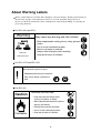
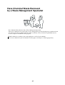
TECHNICAL
GUIDE
SILVER DIGIPLATE
α SYSTEM
Ver.1.01
MITSUBISHI GRAPHIC ARTS SYSTEM
Thank you very much for purchasing the SILVER DIGIPLATE α SYSTEM. This Technical Guide
describes the safety precautions, maintenance, and inspection procedures necessary for operating this
system.
Before using this system, carefully read and understand the Technical Guide. Also, place the
Technical Guide nearby so that you can reference the manual whenever necessary and make full use of
the outstanding functions of the SILVER DIGIPLATE α SYSTEM.
WARNING
Be sure to give this operation manual to the personnel using the Silver Digiplate α system.
Write down the address telephone number of nearest office who is dealing Mitsubishi Paper
Mills Ltd. products in case you need to request another copy.
Warnings appear throughout this manual to ensure the safe use of the Silver Digiplate α
system.
Before operating, be sure to read “Using this Technical Guide” and “Using the Silver
Digiplate α System Safely”.
Do not use this system until all of the precautions noted in this technical guide have been
read and understood.
Please strictly follow all laws and regulations applicable to the material in this guide. Please
have the processing chemicals removed by a waste management specialist to ensure
environmental safety.
Mitsubishi Paper Mills Ltd. is not responsible for any damage caused by conditions beyond
our control, such as use of the product for purposes other than those specified, misuse or use
in inappropriate environmental conditions by the customer.
©Mitsubishi Paper Mills Limited 2002
All right reserved. No part of this publication may be reproduced, transmitted, transcribed,
or stored in a retrieval system without the prior permission of Mitsubishi Paper Mills Ltd..
i
ii
Using this Technical Guide
Limit of responsibility
Every effort has been made to make the contents of this technical guide clear and easy to understand,
but should any information be unclear, inaccurate or missing, please contact Mitsubishi office or local
sales channel.
Mitsubishi Paper Mills Ltd. is not responsible for any damage caused by conditions beyond our
control, such as use of the product for purposes other than those specified, misuse, or use in
inappropriate environmental conditions.
Should any faulty part be found due to a lack in our manufacturing facilities, we will replace it with a
new one. We are not responsible for any faulty parts that are caused by other circumstances.
About misuse of these processing chemicals
We have made every effort to manufacture our processing chemicals to be as safe as possible, but it is
not possible to eliminate all potential dangers. Please thoroughly understand all cautions concerning
safety and correctly follow safety procedures.
Please be sure that all personnel handling these processing chemicals are acquainted with the safety
procedures and follow them completely.
iii
Warning Labels
Before handling any processing chemicals, be sure to read the section entitled, “Warning Labels”.
Mishandling of processing chemicals and failure to read warning labels may result in fire, burns, or
inflammation of the eyes.
The warning labels, attached to the packaging, are intended to warn personnel handling processing
chemicals or any other personnel who might be close by that potential dangers exist.
Three different words are used to indicate warning, “Danger”, “Warning” and “Caution”.
Danger:
Indicates and extremely dangerous situation which will result in serious injury or
death unless avoided.
Warning: Indicates a potentially dangerous situation which may result in serious injury or
death unless avoided.
Caution: Indicates a potentially dangerous situation which may result in minor or more
serious injury unless avoided. “Caution” is also used with respect to dangerous
operations.
“Danger” and “Warning” are used to indicate a danger of material damage that includes a
danger of physical injury.
“Caution” can be used to indicate a danger of material damage only, damage that does not
include a danger of physical injury.
“Note” indicates situations less serious than “Caution” or simple information about how to
handle the processing chemicals carefully.
Danger
Danger
Warning
Caution
(Cause is indicated)
Warning (Cause is indicated)
Caution
(Cause is indicated)
iv
About Warning Labels
All the caution labels used on this Silver Digiplate α System (Danger, Warning and Caution) are
shown below together with explanations of how to avert the particular danger involved.
Be sure to follow the instructions on the warning labels when using, handling, or replacing the
processing chemicals.
For SDP-αDV and αEDV
Warning
CRROSIVE
May cause eye burning and skin irritation
Wear impermeable safety gloves, safety glasses and
masks.
Use in a well-ventilated location.
Never try to taste or swallow.
Always wash throughly after handring.
Keep out of reach of children.
SENSITIVIZATION
For SDP-αSTII and SDP-αOH
Wear protective gloves & glass.
Repeated processing of chemicals
may cause allergic reactions to
skin.
For SDP-αCL
Caution
Flammable liquid and vapor.
• Keep out from the intense heat
sources, fireworks, or flame.
• Wear impermeable protective gloves,
glasses and masks.
• Hermetically seal the container.
• Use in a well-ventilated location.
Flammable
• Keep out of reach of children.
v
Using the Silver Digiplate α System Safely
Be cautious when handling processing chemicals
These processing chemicals are not generally dangerous to humans, but failure to use them in the correct
manner is dangerous. Be sure to handle all processing chemicals with care.
Cautions for handling processing chemicals
(1) Read and understand the safety precautions for handling processing chemicals, and follow the
instructions on the warning labels when using, handling, or replacing processing chemicals.
(2) Handle processing chemicals in a well-ventilated location.
(3) For safety, always wear impermeable protective gloves, glasses, and masks when handling
processing chemicals. Also, always wash your hands thoroughly after your work is completed.
(4) Processing chemicals may irritate the eyes or mucous membranes and may cause allergic
reactions in some people. Do not touch your eyes, skin or clothing immediately after handling
processing chemicals.
(5) Processing chemicals should not be swallowed. As they are harmful, never drink or put them
into your mouth.
(6) In the event that processing chemicals get into your eyes or touch your skin, immediately rinse
the affected area under running water for at least 15 minutes. Remove soiled clothing and shoes
and quickly consult a physician. Wash clothing and shoes well before wearing them again.
(7) In the event that you swallow processing chemicals, immediately call an ambulance and follow
instructions from medical personnel. Unless otherwise instructed, do not vomit or pass anything
from the mouth.
(8) In the even that you inhale vapors from the processing chemicals, move to a place where you
can breath fresh air and quickly follow a physician's orders. If necessary, conduct artificial
respiration.
(9) Store out of reach of children.
(10) Be careful not to cut hands or face on package corners or openings.
(11) Avoid placing processing chemicals in high places or on top of each other in case they fall and
cause injury.
(12) Dispose of all waste products (empty boxes, waste chemicals, Master material stained with
chemicals, etc.) so that they cannot be directly touched by anyone.
Should any faulty part be found due to a lack in our manufacturing facilities, we will replace it
with a new one. We are not responsible for any faulty parts that are caused by the other
circumstances.
vi
Have Chemical Waste Removed
by a Waste Management Specialist
Have Chemical Waste Removed by a Waste Management Specialist
Please have chemical waste removed by a waste management specialist. Pouring waste chemicals down
the drain is hazardous to public health. As failure to abide by safety restrictions is punishable by law,
be sure to dispose of chemical wastes properly.
Handle chemicals according to laws and regulations as well as local standards.
Place waste chemicals in special containers for this purpose and dispose of them appropriately.
vii
Contents
INTRODUCTION ................................................................................. 1
Chapter 1 Overview of Silver Digiplate α .................................................. 2
1-1. Products of Silver Digiplate α system .....................................................................
1-2. Specification of SDP-αRII ......................................................................................
1-3. Specification of SDP-αV .........................................................................................
1-4. Features of Silver Digiplate α ..................................................................................
2
2
3
4
Chapter 2 Silver Digiplate α System and Materials ............................. 5
2-1. System workflow ..................................................................................................... 5
2-2. Applicable press for SDP-α system ......................................................................... 5
2-3. Specification for specially designed processor ........................................................ 5
2-4. Processing agent exclusively used for Silver Digiplate α (SDP-α) ......................... 7
2-5. Packaging ............................................................................................................... 10
Chapter 3 Silver Digiplate α Principle and Process ........................... 11
3-1. Silver Digiplate α (SDP-α) principle .....................................................................11
3-2. Silver Digiplate α (SDP-α) platemaking process ...................................................11
3-3. Silver Digiplate α (SDP-α) Printing process ......................................................... 12
Chapter 4 Silver Digiplate α Platemaking (Output) Method............... 14
4-1. Condition setting of platesetter ..............................................................................
4-2. Precautions for outputting the plate after processing.............................................
4-3. Determination of optimum exposure level ............................................................
4-4. Assessing method ...................................................................................................
4-5. Daily control for optimum exposure level .............................................................
4-6. Calibration .............................................................................................................
14
14
15
15
16
16
Chapter 5 Storing of Plates ............................................................... 17
5-1. Storing unexposed plates .......................................................................................
5-2. Storing of plate (after processing ) ........................................................................
5-3. Storing plate after printing .....................................................................................
5-4. Handling plate after processing .............................................................................
17
17
18
19
Chapter 6 Correction of Image .......................................................... 20
6-1. Deleting method ..................................................................................................... 20
6-2. Felt Pen method ..................................................................................................... 21
Chapter 7 Printing Auxiliary Material for SDP α System.................... 23
7-1. SDP-αOH .............................................................................................................. 23
7-2. SDP-αCL ............................................................................................................... 23
7-3. SDP-αOA .............................................................................................................. 24
Chapter 8 Standard Setting and Maintenance of Processor ............. 25
8-1. P-α880 and P-α880 Eco RF .................................................................................. 25
Chapter 9 Handling Waste Chemicals ............................................... 28
9-1. Aluminum plate ..................................................................................................... 28
9-2. Processing chemicals ............................................................................................. 28
Chapter 10 Troubleshooting .............................................................. 29
10-1. During platemaking ............................................................................................. 29
10-2. During printing .................................................................................................... 31
INTRODUCTION
Since first releasing the Silver Master (SLM) direct-camera platemaking system that successfully
applied the Diffusion Transfer Reversal (DTR) process, which is a kind of the silver halide printing
technology, back in 1974, Mitsubishi Paper Mills Ltd. has been at the forefront of direct prepress
technology.
The digital plate of this direct prepress system is our SILVER DIGIPLATE (SDP). The SILVER
DIGIPLATE α SERIES, which is compatible with the CTP (Computer to Plate), is an advanced
system developed for aluminum plate processing based on this direct prepress technology.
Before using this system, carefully read and understand the Technical Guide. Also, place the
Technical Guide nearby so that you can reference the manual whenever necessary and make full use
of the outstanding functions of the SILVER DIGIPLATE α SYSTEM.
-1-
Chapter 1 Overview of Silver Digiplate α
1-1. Products of Silver Digiplate α system
The SDP-αRII is a silver halide aluminum plate specially designed for Red laser diode.
The SDP-αV is an aluminum plate specially designed for Violet laser diode.
1-2. Specification of SDP-αRII
Table 1-1. Specification table of SDP-αRII
Plate
SDP-αRII
Base
Anodized aluminum
Plate gauge
0.15, 0.20, 0.24, 0.30 mm (0.24, 0.30 for 8-up format)
Light sensitivity
Red sensitivity (630 nm to 680 nm)
Photographic sensitivity Approx. 2 µJ/cm2 (670 nm), Approx. 30µJ/cm2 (488 nm)
Safety light
Dark green (Encapsulite T-40)
Plate Technology
Internal DTR technology
Resolution
Depends on resolution of the platesetter
Dot repeatability
2 to 98% Maximum screen ruling and dot range depends on the platesetter
Possible run length
Up to 200,000 sheets (Depends on the platesetter)
Ex) DS PF-R1050: 175lpi per 50,000 sheets.
Ink compatibility
Commercial ink, desensitized ink, and also compatible with UV ink
Correction
Corrected with specially designed SDP-αOE · Pen
Plate storage
Approx. 1 week after prepress process
Approx. 6 months with SDP-αOH after printing
Processing procedure
Developing / Wash off / Gumming
Processing chemical
Developer : SDP-αDV, SDP-αEDV (exclusively used for αEco processor)
Stabilizer : SDP-αST II
Gum
: SDP-αGum (Finishing solution)
Comparative sensitivity
Fig. 1-1 Photosensitive wavelength and sensitivity of SDP-αRII
350
400
450
500
550
Wavelength
-2-
600
650
700nm
1-3. Specification of SDP-αV
Table 1-2. Specification table of SDP-αV
Plate
SDP-αV
Base
Anodized aluminum
Plate gauge
0.15, 0.20, 0.24, 0.30 mm (0.24, 0.30 for 8-up format)
Light sensitivity
Violet sensitivity (up to 430 nm)
Photographic sensitivity Approx. 3 µJ/cm2 (410 nm)
Safety light
Yellow-Gold, cut-off below 500 nm (Encapsulite YG-10)
Within 5 min. exposure time at 200 lux
Plate Technology
Internal DTR technology
Resolution
Depends on resolution of the platesetter
Dot repeatability
2 to 98% Maximum screen ruling and dot range depends on the platesetter
Possible run length
Up to 200,000 sheets (Depends on the platesetter)
Ink compatibility
Commercial ink, desensitized ink, and also compatible with UV ink
Correction
Corrected with specially designed SDP-αOE · Pen
Plate storage
Approx. 1 week after prepress process
Approx. 6 months with SDP-αOH after printing
Processing procedure
Developing / Wash off / Gumming
Processing chemical
Developer: SDP-αDV, SDP-αEDV (exclusively used for αEco processor)
Stabilizer: SDP-αST II
Gum: SDP-αGum (Finishing solution)
Sensitivity ratio
Fig. 1-2 Photosensitive wavelength and sensitivity of SDP-αV
350
400
450
Wavelength
-3-
500nm
1-4. Features of Silver Digiplate α
1-4-1. Features of system
(1) The direct exposure on the plate with a laser allows repeatable sharp images on printings.
(2) The direct exposure on the plate with a laser allows outstanding repeatability of thin lines and
dots.
(3) The direct exposure on the plate with a laser can avoid particles, dust, or operation errors that
may be caused during the process in which images are exposed from the imagesetter media (film
prepress process) to the conventional plate.
(4) The SDP-αV can be processed in a bright yellow light room.
It is also compatible with the manual loading type platesetter.
1-4-2. Features of plate
(1) The Silver Digiplate α is provided with a resolution that can accurately record a sharp digital
image on the platesetter.
(2) As the image area (precipitated silver area) is black, and the non-image area has the color of the
aluminum plate, it has become easier to inspect the plate after processing compared with the
conventional plate or any other CTP-compatible plate.
(3) It is possible to correct the image area.
(4) It is possible to store the plate.
(5) The unused plates can be stored in the better condition compared with other CTP plates.
-4-
Chapter 2 Silver Digiplate α System and Materials
2-1. System workflow
The Silver Digiplate α (SDP-α) is the material used for the platemaking process in the CTP system.
On that account, the complete digital data (text and image) created via the DTP system is
indispensable.
2-2. Applicable eqipment for SDP-α system
Table 2-1. Applicable equipment
Specially designed processor
P-α880, P-α880 Eco RF (Mitsubishi Paper Mills Ltd.)
Platesetter compatible
PF-R1050 (Dainippon Screen Mfg. Co., Ltd.)
with SDP-αRII
Tigar Cat, Wild Cat (ECRM), ImageMaker B1/B2(Purup-Eskofot)
Platesetter compatible
SDP-α2500V (Mitsubishi Paper Mills Ltd.)
with SDP-αV
Prosetter 52/74/102 (Heidelberg)
GalileoVS/VXT/V4 (Agfa)
Viking 4/8(BARCO), Cobalt 4/8 (Escher-Grad)
Platedriver B1/B2(Purup-Eskofot), Blue Dolphine 6182 (ECRM)
Platium(HighWater)
Note) The processor specified by Mitsubishi Paper Mills Ltd. is required for developing via the SDP-α
system.
2-3. Specification for specially designed processor
Table 2-2. Specification of P-α880
Processor
P-α880 Eco RF-H, W
P-α880
0.15 to 0.30mm
Same as the one on the left
Plate size
Thickness
(0.006" to 0.012")
Width
100 to 820mm *1
100 to 880mm
(4" to 32.3")
(4" to 34.6")
260 to 1030mm
340 to 1030mm
(10.2" to 40.6")
(13.4" to 40.6")
Developer
Not used
17(4.5 US gal.)
Wash-off 1
14.6(3.9 US gal.)
Same as the one on the left
Wash-off 2
6(1.6 US gal.)
Same as the one on the left
Transfer speed (cm/min)
50 to 240
Same as the one on the left
Brush roller rotation speed (rpm)
40 to 120
Same as the one on the left
From plate supply to plate discharge (sec)
35 to 105
30 to 100
Length
Tank capacity (liter)
-5-
Processor
P-α880 Eco RF-H, W
P-α880
Pre-Process section
30 to 70ºC(86 to 158ºF)
Not used
Developer section
Not used
18 to 30ºC(65 to 86ºF)
Wash-offf section
30 to 35ºC(86 to 95ºF)
Same as the one on the left
Dryer section
30 to 65ºC(86 to 145ºF)
Same as the one on the left
Not used
Area, oxidation, oxidation during
Temperature control
Replenishing method
Developer section
inactivation, manual
Wash-off section
Area, vaporization, vaporization
Same as the one on the left
during inactivation, manual
Gum roller cleaning method
Auto cleaning with stabilizer
Same as the one on the left
Power supply
Single-phase 180-254V 16A
Same as the one on the left
Ground wire
Specified manner grounding
Same as the one on the left
Outer dimensions (W × D × H)
1220 × 1340 × 970 *2
1220 × 1170 × 970
(mm)
48.0"×52.75"×38.2"
48.0"×46.0"×38.2"
Without processing chemical
232kg(511lbs)
195kg(430lbs)
With processing chemical
252kg(566lbs)
232kg(511lbs)
15 to 25(59 to 77ºF)
Same as the one on the left
40 to 70
Same as the one on the left
Weight
Environmental conditions
Temperature (ºC)
Humidify (%)
*1) A plate width within a range of 100(3.9") to 635(25") mm can be processed on the SDP-αEco RF-H.
*2) The height of the equipment should be 1080 (42.5")mm when the SA stand is installed.
Fig. 2-1. General view of P-α880
-6-
2-4. Processing solution exclusively used for Silver Digiplate α (SDPα)
The SDP-α is the CTP plate on which the silver halide photographic emulsion is coated. For that
reason, other processing chemicals that are used for the imagesetter media or the CTP plate cannot
be used for the SDP-α.
2-4-1. Platemaking processing solution
(1) SDP-αDV, αEDV (Developer)
The SDP-αDV is the developer that is exclusively used for the Silver Digiplate α system. This
developer enables the image creation, gelatin swelling, and an increase in the image lipophilic
features.
The SDP-αEDV is the developer that is exclusively used for the Silver Digiplate αEco system. It has
the same function as the one of αDV.
The SDP-αDV and αEDV can be only used in the designated developing system.
Packaging/
20 liters plastic canister(Europe), 2.5 US gal. cubitainer(U.S.),
10 liters plastic cubitainer(Other countries)
Shelf life/
Before opening the cap : One year
After opening the cap : One month
Do not freeze the solution.
Concentration/
Ready to use. It can be used as a replenishing solution.
Exchange cycle/ SDP-αDV:
When it is used for P-α880
Every 4 weeks or every 500 m2 (Approx. 600 plates for 8-up format,
approx. 1300 plates for 4-up format)
SDP-αEDV: Exclusively used for P-α880 Eco RF
It should be handled in the same manner as that of the replenishing solution
(due to the coater developing system).
When handling these extremely alkaline chemicals, wear protective glasses and
gloves to ensure safety.
Warning
(2) SDP-αSTII (Stabilizer)
The SDP-α STII is the wash off solution and stabilizer that is exclusively used for the Silver
Digiplate α system. It helps to stimulate the developer neutralization, emulsion layer coagulation
(e.g. gelatin), lipophilic process of the image, and to prevent solution putrefaction.
Packaging/
Shelf life/
Concentration/
20 liters plastic canister(Europe), 2.5 US gal. cubitainer(U.S.),
10 liters plastic cubitainer(Other countries)
Before opening the cap : One year
After opening the cap : One month
Should be stored within a range of 10 to 25 °C(50 to 77°F).
Do not freeze the solution.
Stabilizer: water = 1 : 4
It can also be used as replenishing solution.
-7-
Exchange cycle/
When it is used for P-α880 or P-α880 Eco RF
Every 2 weeks or every 250 m2 (Approx. 300 plates for 8-up format, approx.
650 plates for 4-up format)
When handling these extremely alkaline chemicals, wear protective glasses and
gloves to ensure safety.
Warning
(3) SDP-αGum (Finishing or Gum solution)
The SDP-αGUM is a finishing solution that is exclusively used for the Silver Digiplate α system. It
helps to prevent deterioration of the image area (due to oxidation) and an oxidation stain on the nonimage area from occurring. It also helps to optimize the ink acceptability on the image area (increase
in lipophilic features), and to protect the plate surface.
Packaging/
Shelf life/
Concentration/
Exchange cycle/
2.5 US gal. cubitainer(U.S.), 10 liters plastic cubitainer(Other countries)
Before opening the cap : One year
After opening the cap : One month
Do not freeze the solution.
Ready to use. Fill the special container with 5 liters of the Gum.
When it is used for P-α880, P-α880 Eco RF
Exchange all 5 liters of the Gum at the same time every week, or exchange all
the Gum when a concentration problem occurs (e.g., inappropriate amount of
Gum on a certain area of the plate).
The concentration condition varies depending on the equipment installation
environment.
Note) Circulate the supernatant solution.
-8-
2-4-2. Processing agents for printing
• Fountain solution
SLM-OD · PSIII 10 liters (should be diluted with water between 1 and 2 %)
• Additive for deterioration-prevention of fountain solution
SLM-OA1
1 liter (add 0.5 to 1% in the fountain solution to be used)
SDP-αOA
1 liter (add 0.5 to 1% in the fountain solution to be used)
• Correction pen
SDP-αOE · Pen Bleach type (× 3 pcs.)
• Plate cleaner
SDP-αCL 1 liter (Also used for the conventional plate)
• Plate preserver
SDP-αOH 1 liter (For plate storage)
• Stain-prevention agent during printing(MPM do not supply to U.S.)
AT-1 150 g in a tube, 5 kg in a can (add 3 to 5 %)
AT-2 1 kg in a polyester bottle or 4.5 kg in a polyester bottle (add 1 to 2 %)
Note) If the SDP-α product name is labeled on the agent, it is a processing agent that can be
exclusively used for the α system.
If the SLM product name is labeled on the agent, it is a processing agent that can be used not
only for the α system but also our Silver Master System and Silver Digiplate System.
-9-
2-5. Packaging
The SDP-α is packed in a dark-room loading package. One box contains either 25 or 50 plates, and
they are wrapped with a package paper, and then packed in a carton box.
The box for 25 plates or 50 plates can be identified based on the weight per box.
The maximum size of the plate for a box that contains 50 plates is 755 × 635 mm. If the plate that is
larger than this size is to be packed, a box for 25 plates should be used.
The size of the plate is shown as “A × B”. In this case, the side indicated as “B” is the one that is
parallel to the aluminum grain (grain of the interleaf paper). When ordering, make sure to write
down the size in the appropriate order.
Fig. 2-3. Package for Dark-Room loading
AXB
Y
4 ) & & 5 4
Y
& .
/ 0
SILVER-DIGIPLATE
For Dark-Room Handling
SIZE
670 X 560 X 0.24mm
CONTENT
50
****
SHEETS WEIGHT y
EM NO. **** **
****
EXPIRE y
SDP-αV
SILVER-DIGIPLATE
SDP-αV
SPEC
SILVER-DIGIPLATE
SDP-α 7
[Handling carton]
Note) When transporting the cartons, take special care not to make any damages or dents on the
corners.
Basically, the Dark-Room loading carton should be carried while the opener of the box is
positioned along a vertical direction.
- 10 -
Chapter 3 Silver Digiplate α Principle and Process
3-1. Silver Digiplate α (SDP-α) principle
The SDP-α is a CTP direct offset plate that applies the Diffusion Transfer Reversal (DTR) process,
which is a silver halide photographic technology. This plate consists of the positive layer and the
silver halide emulsion layer that are both formed on the anodized aluminum base.
Fig. 3-1. Structure of Silver Digiplate α
Silver halide emulsion layer
Positive layer
Aluminum base
3-2. Silver Digiplate α (SDP-α) platemaking process
The following is the platemaking process performed on the SDP-α:
Exposure → Development → Stabilization (Wash off) → Gum (Finishing)
(1) Exposure
The SDP-α is a plate that can be used for platemaking process whereby the non-image area is
exposed on the platesetter which is equipped with a laser beam.
On the contrary to the exposure process performed on the standard imagesetter, the SDP-α requires
negative (invert) exposure where text and image area remains unexposed and non-image area is
exposed by the scanning laser beam of the platesetter.
When the SDP-α is exposed by the laser beam, a latent image is formed in the photographic
emulsion layer on the photosensitized SDP-α.
Fig. 3-2. Process diagram of Silver Digiplate α
Exposure unit
(laser beam)
Exposure table
Ex) SDP-α2500V
Processor
SDP-αV
- 11 -
(2) Developing
When developing the SDP-α exposed by the
laser beam, the latent image formed in the
emulsion layer reacts with the developer
(αDV, αEDV [alkali]). Because of this, the
silver halide in the exposed area becomes the
developed silver, which is black. In the
unexposed area, the silver halide is diffused
to the positive layer, and then the metal silver
image is formed.
Laser beam
Silver halide emulsion
Positive layer
Aluminum base
(3) Stabilizing (Wash off)
After the SDP-α is developed, it will be
soaked in the stabilizer (αSTII [slightly
acid]) and neutralized. At this point,
unnecessary silver on the non-image area is
removed, and the image is then processed to
be lipophilic.
Non image area
(anodized layer)
Image area (silver)
Aluminum base
(4) Gum (Finishing)
As the final process, Gum (αGum) is
processed to prevent oxidation (deterioration)
on the image area and an oxidation stain on
the non-image area from occurring, and to
optimize the ink acceptability (increase
lipophilic features) on the image area.
Water
Ink
Water
αGum
Aluminum base
Fig. 3-3. Development → Gum process
diagram
3-3. Silver Digiplate α (SDP-α) Printing process
The following precautions should be noted when printing the SPD-α output through the platemaking
process.
3-3-1. Fountain solution compatibility
The fountain solution, which is used for the conventional plate, can be also used for the SDP-α.
Note, however, that using different types of fountain solution can deal with the low plate durability
for printing or stain (oxidation stain) problem.
The recommended fountain solution is the SLM-OD · PSIII (Mitsubishi Paper Mills Ltd.) and
Astromark III (NIKKEN CHEMICAL CO., LTD.).
Note) If a stain problem occurs on printings, add the additive agent SLM-αOA to the fountain
solution to remove the stain. However, if the additive agent added to the fountain solution is
more than the desired amount, the stain cannot be removed completely. Make sure not to add
more than 2.5 % of the additive agent.
- 12 -
3-3-2. Hydrophilic nature
The SDP-α has an extremely high ability to retain water, almost as much as the conventional plate.
Note, however, that a stain may be found on the SDP-α if it is processed with the maximum
reduction of fountaion solution that can be set for the conventional plate.
3-3-3. Ink compatibility
Conventional offset ink, UV ink, and desensitized ink can be also used.
3-3-4. Solvent resistance
Although each solvent that is used for the conventional plate can be used without being diluted, there
are some commercial plate cleaners that may delete the images through excessive action. Check the
features of each commercial solvent before using.
3-3-5. Plate durability for printing
The plate durability for printing varies depending on the platemaking or printing conditions. For
reference, when Heidelberg Prosetter (Internal drum type platesetter) is used with the P-α880 or the
EcoRF, durability of 200,000 plates under the condition of 175 lines at 2400 dpi is the standard.
When the Screen PF-R1050 (Flatbed type platesetter) is used with the P-α880 or the EcoRF,
durability of 50,000 plates under the condition of 175 lines at 2400 dpi is the standard.
- 13 -
Chapter 4 Silver Digiplate α Platemaking (Output) Method
The Silver Digiplate-α (SPD-α) is the plate that is used under the CTP system, in which the text and
the images in the document completed on the DTP system or the CTS (Computer type-setting
system) is exposed with a laser beam in the platesetter.
4-1. Condition setting of platesetter
(1) Select the SDP-α that complies with the laser diode or the specifications of the platesetter.
Table 4-1. Products of Silver Digiplate-α (SDP-α) (Refer to “Packaging” on Page 10)
Compatible
Type
Spec
Thickness (mm)
laser diode
Violet
Red
No. of plates
Remarks
in package
SDP-αV
SDP-αRII
Yellow light loading
Dark-Room loading
0.2, 0.24, 0.3
25 plates
0.15, 0.2, 0.24, 0.3
50 plates
0.2, 0.24, 0.3
25 plates
0.15, 0.2, 0.24, 0.3
50 plates
Up to 25kg(55lbs)
Up to 25kg(55lbs)
Note) As there are limitation specifications regarding the thickness and the No. of plates in a
package, contact your local distributor before purchasing.
(2) Exposure setting for the SDP-α should be specified in the “Negative output”.
A inverted black/white image is output compared with the case in which image is output on the
media for the imagesetter. As the plate is used for the offset printing as it is, non-reversed image
is output as a result.
(3) Before making an SDP-α plate, make sure to perform a test exposure so that the optimized
exposure conditions can be determined for the particular system. (The appropriate exposure
conditions vary depending on the performance of the platesetter.)
4-2. Precautions for outputting the plate after processing
(1) Set the negative output mode to the non-reversed image.
(2) As the output of the plate should be set according to the plate size to be used on each printing
press, make sure to create and output the data that accurately corresponds to the gripper size and
the full size plate exposure for the particular printing press.
(3) Output the image with an appropriate exposure level. (Mitsubishi Paper Mills Ltd. has released
the SDP Control Chart and the SDP Color Control Chart used for calculating and controlling the
appropriate exposure level.)
(4) Set the environment (e.g., temperature, humidity) for exposure according to the specifications of
the platesetter.
- 14 -
4-3. Determination of optimum exposure level
For the SDP-α, the standard exposure level is determined according to the exposure level, at which
point the reproduction of the hairline image is optimized on the plate. When determining the
standard exposure value, first obtain the laser intensity with which the positive and negative thin
lines are reproduced equally on the plate (as in the SDP Control Chart). (If a similar machine output
pattern is provided in the platesetter, use the pattern.)
On the SDP-α, after the exposed (black) area is removed, the non-image (hydrophilic) area is
created, then the unexposed area becomes the silver image (lipophilic). At this point, if the plate is
exposed with high laser intensity (over exposure), the image area becomes thinner: if the plate is
exposed with lower laser intensity (under exposure), the image area becomes spread.
Therefore, setting of the appropriate exposure level is the critical point to optimize the
reproducibility of the image. (If the exposure level is too high, it may cause dropout of the thin line:
if it is too low, it may cause a stain on printings.)
Depending on the platesetter, the optimum exposure is set to lower than standard so that the
reproducibility can be improved for the thin lines. (Flat bed type of platesetter)
4-4. Assessing method
As in Fig. 4-1, plates should be made by exposing the positive and negative thin lines while varying
the laser intensity in the platesetter machine pattern, or by preparing the image data (e.g., SDP
Control Chart) and exposing the image while varying the laser intensity.
By examining the exposed plates with a 50X loupe you will be able to determined the standard
exposure level (in terms of reproducibility). Based on the determined exposure level, calculate and
set the exposure value appropriate for the particular platesetter.
Fig. 4-1. Assessing exposure level
Under exposure
Standard exposure
Over exposure
Exposure level
Scumming, spread of tint and linework
Image dropout, thinner tint and linework
Standard exposure
- 15 -
4-5. Daily control for optimum exposure level
(1) Daily check
Mitsubishi Paper Mills Ltd. provides the SDP Chart and the SDP Color Control Chart that are
necessary for checking the SDP-α system. Use the tools in those charts to assess the optimum
exposure level on the output plate.
Due to the silver halide photographic emulsion coated on the SDP-α, the sensitivity may vary
slightly depending on the manufacturing lot. If you use plates manufactured in different lots (lot
number is indicated on the external box), make sure to check the sensitivity for each plate.
4-6. Calibration
(1) On-plate control
When outputting the SDP-α from the platesetter, calibration is usually performed so that the intended
dot area ratio can be reproduced on the plate. In order to perform the calibration, first output a test
image that includes the dot wedge (RIP-customized pattern, normally), measure the dot area ratio on
the plate (*a), and then input the measured value (*b).
Even though the calibration can be performed through the procedure described above, if it is
necessary to reproduce the image (at the same level as the one for the present film on the
conventional plate system), more accurate calibration should be performed. In such a case, perform
calibration following the precautions as below.
*a: How to calculate area ratio
The dot area ratio on the plate can be measured by the dot analytic unit or densitometer with a CCD
camera . Since the dot area ratio of the SDP flexible plate, which is our CTP media, can be calculated
from the concentration of the image on the plate, the densitometer, such as Viplate (with a function
of measuring the area ratio on the plate) can be used for measurement. Note, however, that this
densitometer is not compatible with the SDP-α.
If recalibration is necessary, contact your local distributor.
*b: Precautions for inputting image area ratio
When inputting the calibration value for dots, make sure to check that the negative and positive is
correctly set for the RIP.
In order to avoid any mistakes, set to positive for the RIP so that the negative image can be finally
output on the plate.
Ex) Front end system(Positive) → RIP (Positive) → Platesetter (Negative)
- 16 -
Chapter 5 Storing of Plates
5-1. Storing unexposed plates
Store the plate in the proper humidity and temperature (15 to 25 °C, 59 to 77°F) conditions. Relative
humidity should be controlled so as not be over 80 % and temperature should be controlled so as not
to be over 26 °C(79°F). Recommended condition is 20 °C (64°F)and 65 % relative humidity.
Especially in the humid season, pay extra attention to the plate storage condition. Use the stored
plate by the expiration date indicated on the label attached to the box. We do not guarantee the
quality of the plate after the expiration date has passed.
5-2. Storing of plate (after processing )
The rollup performance of the plate (after processing) changes during storage. To achieve the best
printing quality, a stored plate should be printed on the same day as it is output, or on the following
day.
The possible period of plate storage after developing processing depends on processing conditions,
storage environment, printing conditions, and other printing specifications. It is necessary to set the
plate storage period according to the conditions at the customer's site.
Under normal conditions (20 °C, 64°F, 65 % relative humidity), the standard plate storage period for
the plate through normal processing (Development, Wash-off, and Gum processing), is
approximately 7 days. At this point, make sure to use the interleaf paper before wrapping them with
the moisture-proof paper (same paper used for wrapping the SDP-α plate) for storage.
(1) Storing procedure of the plate after processing (for 7 days)
Put the interleaf paper between each plate within 3 hours after processing.
Note) It is recommended to put the interleaf paper between each plate to avoid any scratches on the
plate. (Check the front/rear of the interleaf paper. Make sure that the coated surface of the
interleaf paper is facing the plate surface. Note that the surface you cannot draw on with a
pencil is the coated surface.)
After putting in the interleaf papers, wrap the plates with the moisture-proof paper under a less
humid environment (reference: 20 °C, 64°F, 65 % relative humidity).
The plates can be stored approximately for 7 days.
(Under some conditions, plates can be stored for 2 weeks.)
- 17 -
5-3. Storing plate after printing
Although we do not particularly recommend storage of the plates after printing, if you used the SDPαOH* or process the plates according to the recommended procedure, it is possible to store the
plates for approximately 6 months. When storing the plates, take special care of the storage
environment (standard: 20 °C, 64°F, 65 % relative humidity).
* SDP-αOH: The plate preserver that is exclusively used for the SDP-α system.
(1) Plate storage procedure 1 after printing
Once printing is completed, remove the ink from the plate using the waste paper.
Completely remove the remaining ink on the plate with SDP-αCL, and clean the entire plate evenly
with the SDP-αOH.
Wipe the plate with a dry cloth.
Store the plate in a cool, dry place (standard: below 20 °C, 64°F, 65 % relative humidity).
Note) The plate storage period varies depending on the storage conditions. If the plate is to be
stored for a long period, check the plate condition on your own.
(2) Plate storage procedure 2 after printing
Once printing is completed, remove the ink from the plate using the waste paper.
Use the 2-bath type commercial Gum coater to process the plate with the specified processing
agent*.
Store the plate in a cool, dry place (standard: below 20 °C, 64°F, 65 % relative humidity).
* The compatible processing agents (confirmed up to present) are plate storage processing solution,
solution 1, solution 2 (NIKKEN CHEMISTRY CO., LTD.).
- 18 -
5-4. Handling plate after processing
(1) Spotted stain-prevention
If droplet is adhered to the plate after processing, a spotted stain may occur on the plate. Make sure
not to splash droplets on the plate (be careful not to expectorate).
(2) Fingerprint stain-prevention
Fingerprints can be easily adhered to the plate, especially immediately after the plate is processed.
Also, the longer the plate with the fingerprint is stored before printing, the more distinctively the
stain appears when it is printed.
When handling plates, especially after they are processed, take special care not to leave fingerprints
on the plate.
(3) Scratch-prevention
When carrying a plate to store it in a plate storage box, make sure to use the interleaf paper. If not,
the plate surface may be scratched by another plate’s edge and, and as a result, it appears as a stain
when it is printed.
- 19 -
Chapter 6 Correction of Image
6-1. Deleting method
When correcting the image, use the SDP-αOE · Pen, which is exclusively used for correcting
images. As the images are formed with the precipitated silver on the SDP-α, the images can be
deleted by bleaching the silver image with the SDP-αOE · Pen. (In order to delete the image, the
silver should be removed from the plate.)
Note) The deleting pen used for the conventional plate cannot be used because it is not able to
dissolve the silver.
(1) Image deleting procedure before printing
Before deleting, check that the pen tip is filled with deletion fluid using an unused plate.
Coat, by lightly scratching the image area to be deleted and wait for a couple of seconds.
Lightly scratch the image with the pen tip 5 to 10 times until the image is completely deleted.
Either wipe off the correction fluid or re-wash in the processor.
Fig. 6-1. Deleting method
Image area
SDP-αOE · pen
The images are gradually deleted
- 20 -
(2) Image deleting procedure after printing
Remove the ink from the plate using a waste paper on the printing press.
Completely remove the ink with the SDP-αCL or a recommended plate cleaner *.
Before deleting, check that the pen tip is filled with deletion fluid using an unused plate.
Coat, by scratching the image area to be deleted with the pen tip and wait for a couple of seconds.
Lightly scratch the image with the pen tip 5 to 10 times until the image is completely deleted.
* Refer to the section 7-2. SDP-αCL in Chapter 7.
6-2. Felt Pen method
A commercial felt pen that is used for the conventional plate can also be used. As the specifications
of the pen differs between each manufacturer, check the Instruction Manual before using.
Note) If you scratch the image area with a felt pen for the conventional plate excessively, the image
may be damaged.
- 21 -
- 22 -
Chapter 7 Printing Auxiliary Material for SDP −α System
7-1. SDP-αOH
The SDP-αOH is the plate preserver that is exclusively used for the SDP-α system.
Shake the container well and put the SDP-αOH in a sponge, which has been soaked with the
undiluted solution. Use this solution only in the following cases.
(1) When storing plate after printing (refer to “Storing plate after printing” in chapter 5)
Protect the plate surface from humidity or other potential damages by applying the appropriate
processing on the post-printing plate surface for storing.
(2) When a slight stain occurs during printing.
(3) If poor ink acceptance problem is found during printing.
If the stain cannot be removed with the SDP-αOH, use the SDP-αCL (described below) or a
commercial cleaner recommended by Mitsubishi Paper Mill Ltd.
7-2. SDP-αCL
The SDP-αCL is the multi-functional special cleaner that is used for removing partial ink stains or
oxidation stains in printing, or for removing the ink on the plate during plate storage processing after
printing. Shake the container well before putting it in a sponge, which has been soaked with the
undiluted solution. Use this cleaner only in the following cases.
(1) To remove a slight stain that occurs during printing
The partial ink stain or oxidation stain can be removed.
(2) To prevent a stain from occurring when the process restarts after a short stop during printing
The stain does not occur when the process restarts if the plate is cleaned with this cleaner in
advance.
(3) To prevent a scratch stain from occurring when the printing process starts
To deal with a stain caused by a slight scratch on the plate.
(4) Plate storage up to 2 weeks after printing
If you remove the ink with the cleaner, plate can be stored approximately up to 2 weeks. If you
wish to store the plate longer than this period, first remove the ink on the plate with this cleaner
and dry it with a dry cloth.
(5) It can be used as a cleaner for the conventional plate.
Caution
As these solutions are categorized as “Second Class Petroleum”, do not use them
near a flame.
When using, wear protective gear, such as, protective glasses and gloves.
Note) When using a commercial plate cleaner
There are some commercial plate cleaners that may delete the images with excessive action.
Check the features of each commercial cleaner before using. To assess the compatibility of
the cleaner you are currently using, please contact your local distributor. The following are
the recommended cleaners.
- 23 -
The pH value of the plate cleaner for SDP-Alpha plates should be between 3.0 to 4.0 and
should not include tiny particles for cleaning.
Determine whether the existing plate cleaner can be used for SDP Alpha plates or not by the
following procedure:
(1)Create the 30%tint pattern on the plate.
(2)Put two cottons soaked with plate cleaner on this tint pattern.
(3)Wipe the plate with both cottons and leave them about one hour. After removing cottons, print
the plate.If no dot loss occurs at where the chemical is applied,that plate cleaner can be used for
the plates
7-3. SDP-αOA
(1) Performance
The SDP-αOA is a fountain solution additive agent that has a function to prevent the oxidation stains
or emulsion stains from occurring on the metal plate.
The SDP-αOA is used in the following cases.
(1) To prevent oxidation stain from occurring
Adding 2 % or less of this agent can help to prevent an oxidation stain from occurring on the
plate.
(2) To improve hydrophilic feature
This agent can foster the hydrophilic feature of the fountain solution, as well as prevent an
emulsion stain from occurring.
(3) To help ink to come off from the plate
The ink can be come off from the plate surface more easily by increasing the hydrophilic feature
of the fountain solution. This prevents tint problems from occurring.
(4) To stabilize the fountain solution during a long-run printing
As this agent can help to maintain the viscosity and surface tension of the base fountain
solution, a stabilized quality of fountain solution can be supplied even during a long-run
printing.
(5) Concurrent use with conventional plate
This agent can be also used for the conventional plate.
(2) Precautions for handling the additive agent
(1) If the additive agent is added in more than the specified amount (2.5 %), an over emulsion
problem may occur, and as a result, it may deteriorate the ink rollup feature. Therefore, do not
add this agent in more than the specified rate.
(2) This solution may not help to prevent an oxidation stain, depending on the type of the ink or the
fountain solution used, after the printing press has stopped its operation several times.
(3) If an oxidation stain reoccurs on the plate, wipe off the stain with the special cleaner (SDP-α
CL) or the recommended plate cleaner.
(4) Do not freeze the additive agent (it may turn the agent whitish).
- 24 -
- 25 -
Chapter 8 Standard Setting and Maintenance of Processor
8-1. P-α880 and P-α880 Eco RF
8-1-1. Standard setting
(1) Temperature of developer
The standard temperature of the developer to be set for the P-α880 is 22 °C, 71.6°F (ambient
temperature for the P-α880 Eco RF).
(2) Developing time
The standard developing time is 10 seconds for the P-α880, and 12 seconds for the P-α880 Eco RF.
The developing time should be input in an exponential form from the controller of the processor. The
appropriate developing time may vary depending on the condition of the developer, or the
manufacturing lot of the plate. Check these conditions before setting. (For more detailed
information, contact your local distributor.)
(3) Replenishment rate
As the replenishment rate is one of the critical factors that affects the printability, it should be
specified precisely. If the replenishment rate is too low, it accelerates the deterioration of the
processing chemical, and as a result, it affects the printability (e. g., occurrence of poor ink
acceptance or an unevenness error of tint). On the other hand, it does not affect the printing
performance, even if the rate is too high.
Replenishment in the morning after a period of machine stop is very critical. Occasionally, a
maximum of 5 liters of replenishment may be necessary after 2 days of machine stop, make sure to
check the residual replenishment in the container. For the matter of chemical control, the processor
can be stopped for up to 2 days. If the P-α880 is stopped for more than 3 days, all the developer in
the developer bath must be exchanged. (It is not necessary for the P-α880 Eco RF.)
(4) Plate width setting
The width of the plate to be processed should be input from the controller in the processor. If more
than one type of plate is to be used, the maximum width among those plates should be input in a unit
of cm. The input width of the plate controls the area replenishment rate of the developer and the
stabilizer. (The developer coating rate of the P-α880 Eco RF is controlled in the control box.)
(5) Temperature of stabilizer
As the temperature of the stabilizer is set to 32 °C (89.6°F)in the factory before shipment, it is not
necessary to change the setting.
Note) For information on the changing procedure of each setting, refer to the Operationg Instruction
Manual for the processor.
- 26 -
8-1-2. Maintenance of P-α880
The maintenance cycle of the processor to be performed by the customer is set to “daily”, “weekly”,
or “monthly”. Post the maintenance list near the processor so that the customer can easily refer to the
list and will not fail to perform the specified maintenance.
(1) Precautions for exchanging processing chemical
After exchanging the processing chemical or cleaning the processor, inspect the processor following
the precautions below.
Remove bubbles from the lines.
Check that the developer (αDV) is circulating. If not, bubbles may remain in the circulation lines. In
such a case, remove the bubbles from the lines according to the following procedure. (Refer to the
Operationg Instruction Manual for the procedure on the P-α880 Eco RF.)
(1) Once the chemical is exchanged, turn ON the processor and wait for 3 minutes.
(2) Place a container (over 2 liters) below the developer filter case, to catch the dripping chemical.
(3) To remove the bubbles remaining in the chemical, open the valve located below the developer
filter case while the pump is active.
(4) After fully discharging approximately 500 ml of the developer, close the valve.
(5) The discharged developer should be put back into the developer bath.
(2) Check that the roller in the developer in the developer section is
correctly installed.
(It is not necessary for the P-α880 Eco RF.)
The roller in the developer located in the developer bath is the critical roller that affects the
performance of development on the plate. Adjust the position of the roller according to the following
procedure.
(1) Press the roller, found in the developer, from the top by hand (while the developer remains
discharged) and position the roller to where it contacts the lower guide slightly.
(2) Turn the height adjustment screws for the roller receptacle located at both sides of the roller
clockwise, and check that the roller contacts the guide in the developer bath slightly.
(3) Turn the height adjustment screws one and a half turns counter clockwise, so that the roller in
the developer can be positioned at an appropriate height.
(4) Rotate the roller in the developer slightly by hand to check that the roller does not contact the
lower guide.
(5) If the roller contacts the guide, turn the height adjustment screws one turns more counter
clockwise.
(6) Leave the roller in a condition in which it can be rotated smoothly by hand. (Check that it
rotates when a plate is processed.)
- 27 -
8-1-3. Consumable parts on P-α880
(1) Developer filter
Product specification/10-inch long (254 mm), 75-micron filter (1 pc.)
Replacement cycle/ When developer is exchanged (every 4 weeks or every 500 m2)
Note) The replacement cycle varies depending on the performance of the filter. If a commercial
filter is used, instead of the filter specified by Mitsubishi Paper Mills Ltd., we do not
guarantee that the replacement cycle and the performance will be maintained. (It is not
necessarily for the P-α880 Eco RF.)
(2) Stabilizer filter
Product specification/10-inch long (254 mm), 25-micron filter and 3 micron filter (one of each for 1
set)
Replacement cycle/ When stabilizer is exchanged (every 2 weeks or every 150 m2)
Note) The replacement cycle varies depending on the performance of the filter. If a commercial
filter is used, instead of the filter specified by Mitsubishi Paper Mills Ltd., we do not
guarantee that the replacement cycle and the performance will be maintained.
(3) Developer cloth
Product specification/ Thin cloth roller cover
Replacement cycle/ Monthly (standard)
Note) The replacement cycle varies depending on the No. of processed plates or the width of the
processed plate. When it is torn, replace it with a new one as soon as possible.
(4) Brush roller cover
Product specification/ Navy thick cloth roller cover
Replacement cycle/ Monthly (standard)
Note) The replacement cycle varies depending on the No. of processed plates or the width of the
processed plate. When the non-image area comes out (fails to be removed) from the plate,
replace it with a new one as soon as possible.
Fig. 8-1. Consumable parts
Cover
Filter
Developer cloth
Brush roller cover
- 28 -
Chapter 9 Handling Waste Chemicals
9-1. Aluminum plate
The SDP-α plate has same aluminum base as the industrial aluminum, which is also used for the
conventional plate. Therefore, it can be handled in the same manner as the one for the convensional
plate.
9-2. Processing chemicals
The developer waste chemical should be handled in the same manner as for the silver halide
photograph waste chemical. Please strictly follow all laws and regulations applied by the local
government. (Please contact Mitsubishi Paper Mills Ltd. if the Material Safety Data Sheets are
required.)
* Developer waste chemical: αDV, αEDV, αSTII, αGUM, αCL, αOH, αOA, etc.
9-3. Used filter
Used developer and stabilizer filters include small amount of silver. Therefore, they must be
disposed of by a waste management specialist.
- 29 -
Chapter 10 Troubleshooting
10-1. During platemaking
Trouble
Image error
(during
platemaking)
Symptom
Highlighted dots are too
small.
Possible cause
• Over exposure
• Inappropriate screen
calibration
Dots in shadow area are
too big.
• Under exposure
• Inappropriate screen
calibration
Insufficient density of
non-image area
• Under exposure
• Insufficient wash off
Remedy
• Decrease the laser intensity.
• Perform appropriate screen
calibration.
• Increase the laser intensity.
• Perform appropriate screen
calibration.
• Increase the laser intensity.
• Check that the burush roller
rotates appropriately.
• Replace the brush cover.
Partial black dots appear
• Insufficient wash off
• Exchange the stabilizer.
on plate.
Insufficient density of
image area
• Rewash the plate.
• Gum solution is not
coated appropriately.
• Check the residual Gum in the
Gum tank.
• Temperature of
developer too high or
• Check the developing
temperature and time.
developing time too
long
Tacky Gum
• Concentrated Gum
• Exchange the Gum solution.
solution
• Uneven nip pressure of
• Check the bearing.
Gum roller
Scratch
Fogging in the image
area
• Foreign material exists
in the processor.
• Clean the processor.
• Plate edge touches the
other plates.
• Be careful when handling
plates.
• Safety light fogging in
• Set an appropriate safety light.
the dark room
- 30 -
Trouble
Image error
(during
platemaking)
Symptom
Possible cause
Remedy
Fogging in image area
• Light beam fogging
•Check the light leakage on the
platesetter, if so, shield the
light.
Fade of image color
• Inappropriate storage
condition after
processing.
• Plate was left in the
light for a long period.
• Avoid direct light on the plate
after processing. If possible,
store plates in the moistureproof package.
Dent, breakage
• Inappropriate handling
• Handle plates appropriately.
Irregular thin black dots
• Dust (aluminum) on
platesetter or processor
• Clean the rollers on the
platesetter or processor.
Thin black lines or black
dots
• Dust on mirror or lens
in the platesetter
• Remove the dust using blower,
etc.
- 31 -
10-2. During printing
Trouble
Stain
Symptom
Overall stain or stain in
the course of printing
Possible cause
Remedy
• Too much fountain
solution supply
• Decrease its supply rate.
• Inappropriate fountain
solution
• Change to the recommended
fountain solution.
• Check the dilution ratio.
• Too long plate storage
period
• Plate (before printing) can be
stored for 1 week. Plate (after
printing) can be stored for 6
months if the plate has been
processed with the SDP-αOH.
• Too soft ink or
inappropriate ink
• Change to other type of ink.
• Add 2 to 5 % of varnish.
• High room temperature • Set the room temperature
between 18 and 28 °C for
printing.
• Too much varnish or
reducer
• Keep the limit from 2 to 3 %.
• Too much compound
• Keep the limit from 2 to 3 %.
• Dirty molleton, high
molleton pressure
• Clean it or replace it with a
new one.
• Paper powder
• Change the paper or use a
compound for ink.
• Spray powder
• Minimize the use of spray
powder.
• Wear of form roller
• Check the roller with recovery
agent.
- 32 -
Trouble
Stain
Symptom
Overall stain, stain in the
course of printing
Oxidation stain
Possible cause
Remedy
• Low form roller
pressure
• Adjust it according to the
manual of the press.
• High blanket pressure
• Adjust it according to the
manual of the press.
• Inappropriate molleton
pressure
• Adjust it according to the
manual of the press.
• Old blanket
• Replace it with a new one.
• High fountain solution
temperature
• Decrease the temperature.
• Deterioration of
processing chemicals
• Change the chemical
exchange cycle.
• Inappropriate ink and
fountain solution
• After the stop of the press, dry
the plate by rotating it for 30
sec. while the roller does not
make contact with the plate.
• Wipe off the stain with the
SDP-αCL or recommended
cleaner before printing.
• Add the αOA (2.5 % or lower)
to the fountain solution, or
change the fountain solution
to a recommended one.
• Change to other inks.
Scumming
• Ink susceptible to
• Stain from emulsion ink emulsification was
• Inappropriate ink
used.
(susceptible to
• Keep the limit from 2.5 to 3
emulsification)
• Too much additives
(SLM-OA1, SDP-αOA) %.
• Too much fountain
solution supply
- 33 -
• Decrease its supply rate.
Trouble
Stain
Symptom
Scumming
• High fountain solution
• Stain from emulsion ink concentration
• Inappropriate ink
(susceptible to
• Dirty molleton
emulsification)
Stain by fingerprint
Dropout
Possible cause
Dropout occurred
immediately after the
start of printing
Remedy
• Decrease the concentration
ratio.
• Clean it or replace it with a
new one.
• Deterioration of roller
• Clean the roller with special
cleaner
• Operator touched the
plate while inspecting
the plate after
processing.
• Be careful when handling
plates.
• Wipe off the stain with the
recommended cleaner.
• Too long plate storage
period before printing
• Plate can be stored for 1 week
before printing (standard).
• Wipe off the stain with the
recommended cleaner.
• Deterioration of Gum
• Exchange the Gum base
solution.
• Tacky ink
• Use less tacky ink or put in
additive.
• Do not use tacky ink.
• High developer
temperature
• Set the temperature of the
developer as specified.
• Too long developing
time
• Set the dipping time as
specified.
• Too long shutdown
period of the press
• Use an anti-drying agent or
pre-run the press thoroughly.
- 34 -
Trouble
Dropout
Symptom
Dropout in the course of
printing
Partial dropout
Possible cause
Remedy
• Tacky ink
• Use less tacky ink or put in
additive.
• Do not use tacky ink.
• High developer
temperature
• Set the temperature of the
developer as specified.
• Too long developing
time
• Set the dipping time as
specified.
• Non recommended
solvent has been used.
• Use the recommended plate
cleaner.
• Hard blanket
• Replace it with a new one.
• High plate blanket
pressure
• Adjust it according to the
manual of the press.
• Hard molleton (old)
• Replace it with a one with
lower pressure
• High form roller
pressure
• Adjust it according to the
manual of the press.
• Paper powder
• Change the paper. Clean the
blanket and the plate.
• Partial deterioration of
lipophilic nature
• Apply the SDP-αOH on the
dropout area.
• Apply the SDP-αSTII on the
dropout area.
- 35 -
Trouble
Dropout
Ink poor
acceptance
Symptom
Partial dropout
Ink is not spread at all
Possible cause
Remedy
• Uneven blanket
pressures
• Uneven form roller
pressures
• Uneven molleton
pressures
• Adjust it according to the
manual of the press.
• Unstable ink supply
• Stabilize the ink supply
• Non recommended
cleaner was used.
• Use the recommended plate
cleaner.
• Foreign material is
attached on the plate
• Remove it.
• Deterioration of
processing chemicals
• Exchange the processing
chemical.
• Deterioration of
developer
• Exchange the developer.
• Developer circulation
error
• Remove bubbles from the
lines.
• Low temperature of
developer
• Check for an error in the
processor.
• Tacky ink
• Use less tacky ink or add
additive.
• Emulsified ink
• Clean the rollers and change
the ink.
• Low pressure of the
press
• Adjust it according to the
manual of the press.
• Gum concentrated
excessively
• Exchange the Gum.
• Deterioration of
fountain solution
• Exchange the fountain
solution.
- 36 -
Trouble
Symptom
Possible cause
Ink poor
acceptance
Partially not inked
• Concentrated Gum
• Exchange the Gum.
• Deterioration of
developer
• Exchange the developer.
• Developer circulation
error
• Remove bubbles from the
lines.
• Low temperature of
developer
• Check for an error in the
processor.
• Tacky ink
• Use less tacky ink or add
additive.
• Low room temperature
• Set the room temperature
between 18 and 28 °C for
printing.
• Crashed blanket
(concave)
• Teat with a recovering agent
or replace it with a new one.
• Accumulation of paper
powder
• Clean the plate and the
blanket. Change the paper.
Partially not inked (small • Droplets or spittle are
adhered on the plate
white circle)
immediately after
processing
Remedy
• Make sure droplets are not
adhered on the plate
immediately after processing.
Do not carry the plate in rain.
• Droplets are adhered in • Do not turn OFF the exhaust
the processor area
fan while the processor is
before developing the
being stopped.
plate.
• Clean the inlet roller of the
processor before processing.
• Too long plate storage
time.
- 37 -
• Plate can be stored for 1 week
before printing (standard).
Trouble
Tint pattern
reproduction
error
Symptom
Possible cause
Remedy
• Deterioration of
developer
• Exchange the developer.
• Too short developing
time
• Set the dipping time as
specified.
• Low temperature of
developer
• Set the temperature of the
developer as specified.
• Deterioration of
developer cloth
• Replace it with a new one.
Blurred dots (Doubling
clogged shadow dots)
• High blanket pressure
• Weak blanket tension
• High impression
pressure
• Adjust it according to the
manual of the press.
Emulsified ink
• Too much additive
• Add the appropriate amount of
additive.
• Too soft ink
• Use appropriate ink
• High fountain solution
concentration
• Dilute the fountain solution.
• Mixed with cleaner
• After ink cleaning, reset the
ink.
• Deterioration of roller
• Clean the roller with recovery
agent, or replace it with a new
one.
• Too much additive
(SLM-OA2).
• Keep the limit to 3 %.
Uneven tint pattern
- 38 -
Trouble
Roller
stripping
Symptom
Worn-out inking roller
Possible cause
Remedy
• Insufficient cleaning
• Clean the roller thoroughly, if
necessary, with recovering
agent.
• High fountain solution
concentration
• Decrease the concentration
ratio.
• Mixed with cleaner
• After ink cleaning, reset the
ink.
• Excessive water supply • Decrease the water supply.
- 39 -