1
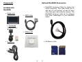
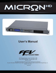
Dear Customer,
DashDAQ Series II
Congratulations! You have just purchased the
most powerful, sophisticated, and easy to use
automotive data logger ever created. The DashDAQ
Series II gives everyone access to the powerful
information embedded in their vehicle. When it
comes to automotive performance, knowledge is
horsepower.
The DashDAQ Series II works with any OBDII
vehicle. It can also be fitted to any other vehicle
using optional add-ons. Now you have a device that
captures information on your new vehicle as well as
your vintage one.
This is an exciting time for vehicle
performance, and the more you know about your
vehicle the more you can get out of it. The
DashDAQ gives automotive enthusiasts the edge in
knowing their vehicle, new or old.
Drew Technologies would like to thank you on
your decision to buy the DashDAQ Series II.
However you use your DashDAQ, we know you will
be satisfied with all aspects of the product. You
demand the best, we deliver the best.
Thank You,
Drew Technologies, Inc.
Instruction Manual
2
Table Of Contents
1
1.1
1.2
1.3
1.4
1.5
1.6
1.7
1.8
2
2.1
2.2
2.3
2.4
2.5
3
3.1
3.2
3.3
3.4
3.5
3.6
4
4.1
4.2
4.3
4.4
4.5
4.6
4.7
4.8
4.9
5
6
Installation...................................... 9
SAFETY FIRST! ..................................................... 9
Attaching Windshield Mount ................................... 9
Windshield Mounting ............................................ 10
Mounting suggestions:.......................................... 10
Cable Routing....................................................... 10
OBDII Connector .................................................. 11
Connections.......................................................... 12
SD Memory Card .................................................. 14
7
8
9
10
11
11.1
11.2
12
12.1
12.2
12.3
12.4
Basic Operation ............................ 15
Low Power Mode .................................................. 15
Menu Navigation................................................... 16
Main Menu Buttons............................................... 18
Menu Map............................................................. 19
New Vehicle Setup ............................................... 20
Gauge Setup & Navigation ........... 21
Navigating Gauges: .............................................. 21
Assign a Signal to a Gauge .................................. 22
Set Gauge Min/Max Values .................................. 23
Set Gauge High/Low Warning .............................. 24
Setting Signal/Graph Colors ................................. 24
Data Logging ........................................................ 26
DashDAQ Setup Menu................... 29
Installed Devices................................................... 29
Clock..................................................................... 33
Install From SD Card ............................................ 34
Backup To SD Card.............................................. 35
Startup Splash Screen.......................................... 36
Default Power-up Screen...................................... 36
Dashboard Theme ................................................ 37
Backlight Brightness ............................................. 38
Logfile Prefix......................................................... 39
Diagnostic Code Reader............... 40
Performance Measurements ........ 42
3
4
Dyno Calculator............................ 44
Fuel Economy Calculator ............. 48
Parameters ................................... 51
Third Party Accessory Setup ....... 51
Updating DashDAQ....................... 52
Install the Windows driver..................................... 52
Update your DashDAQ: ........................................ 55
APPENDIX..................................... 57
Support ................................................................. 57
Technical Specifications ....................................... 58
Limited Warranty .................................................. 59
Accessory Cable Pin Out...................................... 60
Components
Optional DashDAQ Accessories
• DashDAQ Accessory Cable for analog and
serial connectivity. This cable allows you to
add two 0-5 volt sensors, as well as many
other third party data collection devices. The
DashDAQ Accessory cable can be obtained
from Drew Technologies, or your DashDAQ
dealer.
Included with
DashDAQ
• Display Unit
• OBDII Cable
• Windshield
Mount and four
Screws
• Software CD
• SD Memory Card
• USB Cable
5
6
IMPORTANT!
THIS IS A HIGH PERFORMANCE PRODUCT,
USE AT YOUR OWN RISK
Do not use this product until you have carefully read the following
agreement. This sets forth the terms and conditions for the use of this
product. The installation of this product indicates the BUYER has read
and understands this agreement and accepts its terms and conditions.
This agreement takes precedence.
DISCLAIMER OF LIABILITY
Drew Technologies and its successors, distributors, jobbers, and
dealers (hereafter SELLER) shall in no way be responsible for the
product’s proper use and serviceability.
THE BUYER HEREBY WAIVES ALL LIABILITY CLAIMS.
The BUYER acknowledges that he/she is not relying on the SELLER’s
skill or judgment to select or furnish goods suitable for any particular
purpose and that there are no liabilities which extend beyond the
description on the face hereof and the BUYER hereby waives all
remedies or liabilities, expressed or implied, arising by law or otherwise,
(including without any obligations of the SELLER with respect to fitness,
merchantability, and consequential damages) or whether or not
occasioned by the SELLER’s negligence. The SELLER disclaims any
warranty and expressly disclaims any liability for personal injury or
damages. The BUYER acknowledges and agrees that the disclaimer of
any liability for person injury is a material term for this agreement and
the BUYER agrees to indemnify the SELLER and to hold the SELLER
harmless from any claim related to the item of the equipment
purchased. Under no circumstances will the SELLER be liable for
damages or expenses by reason of use or sale of any such equipment.
The SELLER assumes no liability regarding the improper installation or
misapplication of its products. It is the installer’s responsibility to check
for proper installation and if in doubt, contact the manufacturer.
Warning: Minnesota and California
state laws clearly affirm that no person
shall drive any motor vehicle with any
object or material placed, displayed, installed,
affixed, or applied in or upon the windshield or side
windows or anywhere else
which obstructs or
reduces the driver's clear view through the
windshield or side windows. Drew Technologies
does not take any responsibility for any fines,
penalties, or damages that may be incurred as a
result of disregarding this notice. (See Minnesota
Statutes 2005, Section 169.71 and California
Vehicle Code Section 26708(a)). Similar laws may
apply within your province or state. Please verify
your provincial or state laws prior to installation.
Warning: When mounting the DashDAQ
to the windshield, place the device in a
location where it does not obstruct the
driver’s view of the road and does not
interfere with vehicle controls and safety devices or
the safe operation of your vehicle.
IN THE EVENT THAT THE BUYER DOES NOT AGREE WITH THIS
AGREEMENT: THE BUYER MAY PROMPTLY RETURN THIS
PRODUCT, IN A NEW AND UNUSED CONDITION, WITH A DATED
PROOF OF PURCHASE, TO THE PLACE OF PURCHASE FOR A
FULL REFUND. THE INSTALLATION OF THIS PRODUCT INDICATES
THAT THE BUYER HAS READ AND UNDERSTANDS THIS
AGREEMENT AND ACCEPTS ITS TERMS AND CONDITIONS.
7
8
3. Using a Phillips head screwdriver, lightly
tighten each of the four screws. Note: Over
tightening can possibly damage your
DashDAQ. Tighten the screws so they are
snug, no more.
1 Installation
1.1 SAFETY FIRST!
The installation of the DashDAQ must be done in
such a manner that it does not interfere with the
safe operation of your vehicle. If you can not mount
the DashDAQ such a manner, Promptly return the
DashDAQ, in a new and unused condition, with a
dated proof of purchase, to the place of purchase
for a full refund.
1.3 Windshield Mounting
Your DashDAQ must be mounted on your
windshield in a spot that does not obstruct your
view of the road or in any way interfere with the
safe operation of your vehicle.
1.4 Mounting suggestions:
1.2 Attaching Windshield Mount
1. Remove these two items from packaging:
a. Display Unit
b. Windshield Mount
2. Line up the four holes on the windshield
mount and thread each of the four screws
into the display unit.
Find your OBDII port on your vehicle. Plug in the
DashDAQ OBDII connector. Route your cable
safely, (see “Cable Routing” below) and note
where it reaches. Mount the DashDAQ in a spot
that does not obstruct your view based on where
the cable ends.
• Mount the DashDAQ as low to your
dashboard as possible.
• A mount to left or in the middle works well.
1.5 Cable Routing
The DashDAQ OBDII cable must be routed in your
vehicle in a manner that doesn’t interfere with safe
operation of your vehicle.
9
10
Cable routing tips:
• Find your OBDII connector first and work the
cable to where it is to be mounted on the
windshield.
• Route your DashDAQ OBDII cable between
interior panel grooves. These grooves will
hold the cable as well as conceal it.
• Use wire or zip ties to bundle any excess
cable.
1.7 Connections
USB Port.
This port used
for updating
DashDAQ.
Cable routing “Don’ts”
• Don’t let your cable dangle by your feet.
• Don’t let the cable hang free.
• Keep the cable away from the steering wheel
and any steering column controls.
• Golden Rule: If the cable looks to be routed
poorly, it most likely is.
Analog and
serial input
port for
optional
Accessory
cable.
1.6 OBDII Connector
The OBDII or “data link” connector is the basis of
DashDAQ operation. Power as well as all vehicle
information comes from this vehicle link.
Most OBDII connections are found directly below
the steering column. It should be in plain sight. If
you cannot find your OBDII connector have a local
mechanic show you where it is.
11
12
Audio Port
OBDII Port
Connections (cont.)
1.8 SD Memory Card
USB Ports
Always insert and remove the memory card with
the DashDAQ powered off. The SD Memory card
needs to be inserted with the gold connections
facing towards you as you look at the screen. Press
the card into the DashDAQ until you hear a click. If
the card sticks out at all, it has not been pushed in
all the way.
Power Button
MMC SD Memory
Card Slot
To remove, press the card in until you hear the
click again. Release and the card will come all the
way out.
13
14
2 Basic Operation
2.2 Menu Navigation
This section describes the basic operation of the
DashDAQ.
When your DashDAQ first starts up, a boot screen
will appear. Please wait.
2.1 Low Power Mode
Whenever the warning screen appears, read
carefully.
The DashDAQ has a low power mode built in as a
power and time saving convenience. This mode
can be activated from the small black button on the
front left of the DashDAQ. Low power mode keeps
you from having to wait for the DashDAQ to start
up. It has three functions:
• Press and release this button quickly while
the DashDAQ is on. The screen will go off,
but the unit will still be on. Press the button
again and the DashDAQ will instantly come
back on.
• Press and hold the small black button for 3
seconds. The screen will go black. Now the
DashDAQ is completely off.
If you agree and want to continue, tap the [I Accept]
button. If you do not agree, please disconnect your
DashDAQ and contact Drew Technologies for a
return authorization.
• Press again to power the DashDAQ back up.
15
16
Tapping the tap the [I Accept] button will cause the
gauge screen to appear:
2.3 Main Menu Buttons
The [Diags] button takes you to the DashDAQ code
reader. Here you can view and clear codes on any
OBDII vehicle.
The [Setup] button gives access to configuration
options of the DashDAQ. (See DashDAQ Setup
Menu)
The [<<] and [>>] arrow buttons at the bottom allow
you to cycle through different gauge layouts.
The [Main Menu] button in the lower right corner
takes you to the main menu where you can access
all of DashDAQ’s features.
The [Performance] button will direct you to 1/4-mile,
1/8-mile and 0-60 performance measurements.
Select your Vehicle speed sensor and you are
ready to go.
The [Gauges] button takes you directly to the
Gauges screen.
The [New Vehicle] button should be used every
time you connect to a new vehicle. Follow the on
screen
instructions.
The
DashDAQ
will
automatically find all signals that your vehicle
supports. (See New Vehicle Setup)
This button allows you to view and change how the
input signals are displayed.
17
18
2.4 Menu Map
2.5 New Vehicle Setup
The DashDAQ was designed to be used on any
OBDII vehicle. OBDII vehicles have many “signals”
or “parameters” that can be viewed. Each vehicle
you connect the DashDAQ into will have a different
set of parameters or signals available. Run the
New Vehicle function every time you plug the
DashDAQ into a different vehicle. If this is not
done, parameters may show up on the list that
don’t work and parameters that are available may
not be displayed.
The New Vehicle setup:
1. Plug your DashDAQ into the vehicle.
Make sure your vehicle is running and the
DashDAQ is on.
2. Go to the DashDAQ main menu. Tap
[New Vehicle].
3. Follow the on screen instructions. When
the DashDAQ tells you how many signals
are available, you are done.
4. Repeat steps 1-3 every time you connect
the DashDAQ to a new vehicle.
19
20
3 Gauge Setup & Navigation
3.2 Assign a Signal to a Gauge
This section describes how to setup gauges and
navigate.
Before specifying what signal you would like a
gauge to display, make sure the New Vehicle
procedure has been completed.
3.1 Navigating Gauges:
1. To assign a signal to a gauge, select a
gauge screen. Tap on the gauge where you
would like a signal to display. This screen
will appear:
To access DashDAQ gauges, tap on [Gauges] from
the Main Menu. The last gauge layout you selected
or this screen will be displayed.
To change gauge layouts, tap on the [<<] and [>>]
buttons. Here are a few examples:
2. Tap on [Assign Signal]. Notice the [<] and [>]
buttons at the top of the screen.
These allow to switch which DashDAQ input you
would like to use (Optional Accessories). OBDII is
the default. Pick which signal you would like to
monitor and tap [Save].
Every gauge and box can be assigned a
parameter/signal.
21
22
3.3 Set Gauge Min/Max Values
3.4 Set Gauge High/Low Warning
The DashDAQ allows users to specify the data
range for each gauge. Tap on the [Minimum] button
to set the bottom value for a gauge. Tap on the
[Maximum] button to set the top of the gauge.
The High/Low Warning allows users to set the
visual representation of “redline” on a gauge.
When you tap on either [Minimum] or [Maximum]
this screen will appear:
Tap in the desired value. Tap [+/-] to make this
value negative.
For example: If the gauge has a maximum value of
6,000 and you set a High Warning of 5,000, the
gauge will visually represent a “danger zone” on
the gauge.
To set a High/Low Warning:
1. Tap on the gauge that a High/Low Warning is
to be set.
2. At the Assign Signal screen, tap on either
High or Low Warning.
3. Tap the numbers to enter the desired value.
Tap [+/-] to make the value negative. Tap
[Save].
4. Tape [Save] at the Assign Signal screen to
go back to the gauges.
3.5 Setting Signal/Graph Colors
23
24
The DashDAQ allows users to assign different
colors to the signals assigned to a particular
gauge. The signal will be displayed in the color
chosen. To change color values:
1. Tap on a signal box
.
2. Tap on the red, green, and blue swatch in the
corner of the box.
3.6 Data Logging
The DashDAQ is not only a powerful gauge
display, it can also log and save all information
represented on the gauges. This information is
saved to a Microsoft Excel *.csv file to an inserted
SD memory card. This allows you to view and
graph saved vehicle parameters any way they like.
To begin logging:
1. Find a particular gauge layout from which
you would like to capture information. Set all
gauges with the signals you would like to
log.
Note: If you pick a gauge layout with seven gauges,
you can log up to seven parameters/signals to the
log file.
3. Now tap on the color to select. Tap [Save].
4. Tap [Save] in the Set Gauge Properties
window to return to the gauges.
25
2. Tap on [Start Log]. The signals you were
monitoring will be saved to the SD card with
a timestamp. You can continue to monitor
26
the signals displayed on the gauges.
3. When finished with your log session tap
[End Log]. Your results are now saved to the
memory card.
Each time you go through the above three steps,
the DashDAQ saves one file on the SD memory
card. The file is saved in a directory called “log.”
Each saved file has a log prefix. The default prefix
is “log” and can be changed to your liking.
3. Enter the desired name of the log file prefix.
Example: TestDrag. Now tap [Save]. Note:
Now all log files will be saved in numerical
order with the name you entered. Example:
TestDrag0000.csv.
To change the log prefix:
1. From the Main Menu, tap on [Setup].
2. Using the top [<] [>] arrow buttons, move
through the various configuration menus
until you reach the Logfile Prefix option.
To view saved log files: remove the SD memory
card from the DashDAQ. Place the memory card
into a SD card reader and attach to your PC. Open
the contents of the card. Your log files are saved in
the “logs” directory on your card. You can open
your log files in Microsoft Excel or any other
spreadsheet program that accepts *.csv files.
Tap on the highlighted [log] in the black box. This
screen appears:
27
28
3. Tap on a blank space that corresponds to the
letter you would like the driver assigned to.
4 DashDAQ Setup Menu
This section describes the setup menu.
4.1 Installed Devices
The Installed Devices section of the setup menu is
what makes DashDAQ truly unique. Software
drivers are written by Drew Technologies so that
third party devices like Innovate Motorsports,
Blackline GPS, and PLX Devices can be connected
to DashDAQ. Other drivers are available that can
calculate
real-time
vehicle
statistics
like
horsepower and torque.
4. Tap [Change]. This screen appears:
Every connection type has a driver that is specified
in the Installed Devices setup option. OBDII,
analog, and third party accessories are specified
for use here. After a particular driver is loaded, the
signal/s that are specified in the driver will show up
in the signal selection screen when you tap on a
gauge.
Here is an example of setting up the drivers for an
Innovate LC-1 wideband oxygen sensor:
5. Tap [Driver].
1. Tap [Setup] from the Main Menu.
2. Navigate to the Installed Devices setup option
by tapping [<] or [>]. Notice that the drivers
are organized by letter (a, b, c, etc).
29
30
6. To select the Innovate LC-1, use the [<] or [>]
buttons to navigate to the “Wideband”
selection.
To make use of the driver after it has been
selected:
1. Tap on [Gauges] from the Main Menu.
2. Tap on a gauge you would like to assign the
Innovate LC-1 signal to.
3. Tap [Assign Signal].
4. Use the [<] or [>] buttons to navigate to the
Innovate LC-1 heading. Tap [Air-Fuel Ratio]
to highlight.
7. Tap [Innovate LC-1] to highlight the Innovate
LC-1 driver. Tap [Save].
8. Tap [Save] again. Tap [Save] once more at
the Installed Device setup window.
5. Tap [Save]. Tap [Save] again at the Assign
Signal Screen.
This procedure can be repeated for all drivers
found in the Installed Devices setup option.
31
32
4.2 Clock
4.3 Install From SD Card
The clock setup option allows the user to set the on
board clock to current time and date. This
information will be time-stamped into all log files
that you make.
This setup option allows you to install various user
licenses, drivers, and Config files. These files can
be saved with the Backup To SD Card option.
To install any of these three items:
To set the time and date:
1. Tap on [Setup] from the Main Menu. Using
the top [<] or [>] buttons scroll to the Clock
option.
1. Tap on [Setup] from the Main Menu. Using
the top [<] or [>] buttons scroll to the “Install
From SD Card” option.
2. Tap [Set Clock].
2. Tap on the item you would like to install from
the SD Card. When it is highlighted, tap
[Install].
3. Various licenses, drivers, and config files can
be saved to the SD card. Select which file
you would like to install and tap [Ok].
4. Follow the onscreen prompts to make sure
your file is installed successfully.
3. Now tap on the arrows to make the correct
adjustments to the values.
4. Now tap [Save]. Tap [Save] again to make
your changes permanent.
33
34
4.4 Backup To SD Card
4.5 Startup Splash Screen
Backup to SD is the setup option that allows you to
backup various user specific setting of the
DashDAQ. One example is backing up the gauge
setup for all dashboard themes and gauge layouts
within each theme. This is done by backing up
“Config File.”
This setup option allows you choose which image
file you would like to be displayed when the
DashDAQ starts up.
To back a specific license, driver, or config file:
1. Tap on [Setup] from the Main Menu. Using
the top [<] or [>] buttons scroll to the “Backup
To SD Card” option.
4.6 Default Power-up Screen
The Default Power-up Screen setting allows you to
choose which screen the DashDAQ brings up first
whenever it is turned on or rebooted.
2. Tap on the file you would like to backup.
When the file is highlighted, tap [Backup].
3. Follow the onscreen prompts to make sure
your file is backed up successfully.
35
36
4.7 Dashboard Theme
4.8 Backlight Brightness
The DashDAQ has a very powerful graphical
interface that allows its users to change the look
and feel of the gauges. Each theme has different
gauge layouts. The Dashboard Theme option gives
users the ability to switch between these “skins.” By
tapping on a specific theme name and tapping
[Save], the new skin will be instantly loaded.
The Backlight Brightness setup option allows you to
change how bright the screen is.
Gauge layouts
themes.
will
change
between
various
When you tap on [Gauges] from the Main Menu
you will notice the gauges are much different. The
DashDAQ saves gauge signal assignments across
each theme so that you will never have to reassign
gauge parameters twice. This also serves to add
more gauge and signal combinations.
37
38
4.9 Logfile Prefix
5 Diagnostic Code Reader
The Logfile Prefix is the name that is attached to
the beginning of a log file. When you tap “Start Log”
from a gauge screen a file is instantly created on
your SD card in Microsoft Excel Format. This file is
given a name based on the log file prefix and the
number of log files already on the memory card.
This allows you to change the name of your log
files for specific events, ex: Milan_10_10_2007.
The DashDAQ comes with software to be a fully
functional code reader. If your check engine light
comes on, you can check your vehicles diagnosis
of the problem. Once you have read the codes, you
can clear them to turn the check engine light off.
To view and clear diagnostic trouble codes:
Tap on “log.”
1. From the Main Menu tap on Diags.
2. This screen will appear:
Now you can enter your preferred prefix and tap
“Save”.
3. Turn your key to the on position. Your vehicle
does not need to be running.
4. Tap [Read Codes]. If your check engine light
is on, the diagnostic trouble code/s will be
displayed along with a short description of
the code.
5. To clear the diagnostic trouble codes, tap
[Clear Codes]. You will be asked if you want
to clear the codes.
39
40
6 Performance Measurements
1/4-mile, 1/8-mile, and 0-60mph times can be
attained with the DashDAQ. All that is needed to
calculate these measurements is a vehicle speed
sensor signal (OBDII/Aftermarket ECU’s) or a
speed signal from a GPS receiver.
If you want to measure performance:
6. Tap [Yes] if you would like to clear the codes
and turn your check engine light off. Note:
This does not solve any underlying vehicle
issues.
7. Tap [No] if you do not want to clear the
codes.
1. From the Main Menu tap on [Performance].
2. Select the vehicle speed sensor.
3. Select either 1/4-mile, 1/8-mile, or 0-60 by
tapping on the [<<] or [>>] buttons.
41
42
4. Bring your vehicle to a stop and tap [Start].
When the drag-strip “tree” turns green,
accelerate.
5. The measurement will automatically end and
display the result when you have completed
the run.
7 Dyno Calculator
The Dyno Calculator allows you to measure vehicle
horsepower and torque on the fly. These two
measurements are assignable to any gauge. The
ability to assign horsepower and torque values to
any gauge also allows you to log this information
alongside any other available signals.
To setup and use the Dyno Calculator:
1. Tap [Setup] from the Main Menu.
2. Navigate to the Installed Devices setup option
by tapping [<] or [>]. Notice that the drivers
are organized by letter (a, b, c, etc).
3. Tap on a blank space that corresponds to the
letter you would like the driver assigned to.
43
44
4. Tap [Change]. This screen appears:
7. Tap [Dyno Calculator] to highlight the Dyno
Calculator driver. Tap [Save].
8. Tap [Save] again. Tap [Save] once more at
the Installed Device setup window.
The Dyno Calculator needs 3 signals to calculate
horsepower and torque: vehicle speed sensor,
vehicle rpm sensor, and vehicle weight. These
variables can be defined in the Parameters menu
from the Main Menu. Here’s how:
1. Tap on [Parameters] from the Main Menu.
2. Navigate to the “d- Dyno Calculator” option
by taping on the [<] or [>] buttons.
5. Tap [Driver].
6. To select the Dyno Calculator, use the [<] or
[>] buttons to navigate to the “Calculator”
selection.
45
46
3. You will need to tap on each signal and tap
[Change] to specify the values of each.
The DashDAQ is row ready to calculate
horsepower and torque for your vehicle. Navigating
to the Gauges screen will allow you to assign either
signal to any gauge. For example:
1. From the Main Menu, tap on [Gauges].
2. Tap on the gauge you would like to assign
horsepower or torque to.
3. Tap on [Assign Signal].
4. Use the [<] or [>] buttons to find the “d- Dyno
Calculator” option.
5. Tap on either “Calculated Horsepower’ or
“Calculated Torque” and tap [Save].
6. Tap [Save] again to view the calculation on
the gauge.
8 Fuel Economy Calculator
The DashDAQ comes with a driver for calculating
Fuel Economy. This calculation is based off of four
variables: Air-to-Fuel ratio, Fuel Density, Vehicle
Speed sensor, and Mass Air Flow sensor. Once
configured this driver will allow you to assign the
Fuel Economy signal to any DashDAQ gauge. Let’s
get started:
1. Tap [Setup] from the Main Menu.
2. Navigate to the Installed Devices setup option
by tapping [<] or [>]. Notice that the drivers
are organized by letter (a, b, c, etc).
3. Tap on a blank space that corresponds to the
letter you would like the driver assigned to.
4. Tap [Change]. This screen appears:
47
48
Fuel ratio and Fuel Density will be the same for
stock OBDII vehicles and are already preset. The
Vehicle Speed sensor, and Mass Air Flow sensor
will need to be defined, here’s how:
1. Tap on [Parameters] from the Main Menu.
2. Navigate to the “Fuel Economy Calculator”
option by taping on the [<] or [>] buttons.
5. Tap [Driver].
6. To select the Fuel Economy Calculator, use
the [<] or [>] buttons to navigate to the
“Calculator” selection.
3. You will need to tap on the “Speed Signal”
and “Mass Air Flow Signal” to highlight, and
tap [Change] to specify the values of each.
7. Tap “Economy Calculator” to highlight the
Fuel Economy Calculator driver. Tap [Save].
8. Tap [Save] again. Tap [Save] once more at
the Installed Device setup window.
The Fuel Economy Calculator needs four signals to
calculate Fuel Economy: Air-to-Fuel ratio, Fuel
Density, Vehicle Speed sensor, and Mass Air Flow
sensor. These variables can be defined in the
Parameters menu from the Main Menu. Air-to49
The DashDAQ is row ready to calculate fuel
economy for your vehicle. Navigating to the
Gauges screen will allow you to assign this signal
to any gauge. For example:
1. From the Main Menu, tap on [Gauges].
2. Tap on the gauge you would like to assign
fuel economy to.
3. Tap on [Assign Signal].
4. Use the [<] or [>] buttons to find the
“Economy Calculator” option.
50
5. Tap on the desired measurement and tap
[Save]. Tap [Save] again to view the
calculation on the gauge.
9 Parameters
From the Main Menu you can access the
Parameter menu. This menu allows you to change
the scaling and other options associated with an
installed driver. Some examples include: changing
offsets for analog inputs, changing OBDII units to
metric, etc. The Parameters menu allows you to
customize how the data is displayed.
11 Updating DashDAQ
Your DashDAQ’s software is completely updateable. The software necessary to update the
DashDAQ is on the included CD.
11.1 Install the Windows driver
Install the Windows driver (dashdaq.inf) using this
procedure:
1. Important! Connect the USB cable to the
single USB port located on the left side of
DashDAQ as you look at the screen. Any
other USB port will not work. Connect the
opposite end of the USB cable to your
computer.
Note: Currently the USB port on the
DashDAQ is used only for updating the
DashDAQ.
10 Third Party Accessory Setup
Please refer to the website for all information
concerning third party accessories.
2. The Found New Hardware wizard will appear.
Click [Locate and install driver].
www.dashdaq.com
51
52
4. Click on [Browse my computer for driver
software]. You will see this message:
3. Windows will do a preliminary search for the
driver, but will not find one. This screen will
appear:
5. Click on [BrowseQ] and highlight your CDRom drive. Click [Ok]. Now click [Next]. You
will see this screen:
6. Click on [Install this driver software anyway].
Windows will now go through the install
procedure and will tell you when the driver
has successfully installed.
53
54
7. The Select DashDAQ Tool Package screen
will appear:
11.2 Update your DashDAQ:
1. Connect the USB cable to the single USB
port on the left as you look at the DashDAQ
screen, and then to your computer.
2. Go to Start>Programs>Drew Technologies,
Inc> DashDAQ Update Tool
8. Select the firmware file that was downloaded.
Click [Open]. Your DashDAQ will begin
updating.
3. Click on [Check Web For Updates]. This will
download the latest firmware for your
DashDAQ.
4. Take note of what firmware version is being
downloaded. Click [Yes].
9. When you see this screen, the DashDAQ has
been successfully updated.
5. After the download if your DashDAQ is not
listed, click [Refresh List].
6. When you see your DashDAQ listed, click to
highlight it and click [Update Firmware].
55
56
12.2 Technical Specifications
12 APPENDIX
Display
Resolution
12.1 Support
System Processor
Vehicle Bus Processor
RAM
Flash
Memory Expansion
Device I/O
Please be sure to reference our online FAQ’s. All
support questions can be answered at the online
forums at www.dashdaq.com. These forums are
constantly monitored, and will provide you with the
fastest answers.
Vehicle I/O
Expansion I/O
Add-on sensors
Operating temperature
Operating voltage
Current Draw
Dimensions
Weight
Operating System
Warranty
Other Features
Mounting Pattern
Package Contents
57
58
4” COLOR TFT w/touch panel
480 x 272 (QWVGA) w 24-bit color
display
240MHZ ARM9
48MHZ ARM7
64MB SDRAM
16MB Flash
MMC/SD Card 128MB to 8GB+
touch-panel, ambient light sensor, 16bit stereo line-out, 1W speaker, USB
device port, programmable button
CAN, J1850VPW (GM Class 2),
J1850PWM (Ford SCP), ISO9141,
KWP2000
(2) USB Host Ports, (2) RS232 Ports,
(2) 0-5V 10-bit analog inputs
Blackline GPS (up to 20HZ), Innovate
MTS Bus products, 0-5V Wideband O2
Sensors, NMEA GPS, USB 3-axis
Accelerometer, USB K-Type
Thermocouple
-35 to 85C
6 to 30V
200mA at 100% backlight
4.6” x 2.75” x 1”
0.5LB
Linux
factory tested with 1 year warranty
Real Time Clock, locking connectors,
factory tested, field upgradeable
firmware
AMPS 4-HOLE standard
DashDAQ, Vehicle Cable, USB Cable,
Windshield Pedestal, CD-ROM, users
manual
12.3 Limited Warranty
12.4 Accessory Cable Pin Out
Drew Technologies, Inc. guarantees that every DashDAQ Series II is
free from physical defects in material and workmanship under normal
use for one year from the date of purchase. Warranty card must be
mailed within 90 days of initial purchase to activate warranty. If the
product proves defective during this warranty period, email Drew
Technologies Customer Support ([email protected]) in order to
obtain a Return Authorization number and form. When returning a
product, mark the Return Authorization number clearly on the outside of
the package and include a copy of your original proof of purchase and
the form.
IN NO EVENT SHALL DREW TECHNOLOGIES, INC.' LIABILITY
EXCEED THE PRICE PAID FOR THE PRODUCT FROM DIRECT,
INDIRECT, SPECIAL,
INCIDENTAL, OR CONSEQUENTIAL
DAMAGES RESULTING FROM THE USE OF THE PRODUCT, ITS
ACCOMPANYING SOFTWARE, OR ITS DOCUMENTATION.
Drew Technologies, Inc. makes no warranty or representation,
expressed, implied, or statutory, with respect to its products or the
contents or use of this documentation and all accompanying software,
and specifically disclaims its quality, performance, merchantability, or
fitness for any particular purpose. Drew Technologies, Inc. reserves the
right to revise or update its products, software, or documentation without
obligation to notify any individual or entity. Please direct all inquiries to:
Drew Technologies, Inc.
3915 Research Park Dr
Suite A10
Ann Arbor, MI 48108
1
2
3
4
5
6
7
8
Phone: (734) 222-5228
Fax:
(734) 222-5008
9
E-Mail: [email protected]
Warranty is voided if software that has not been
previously authorized by Drew Technologies, Inc. is
installed and or run on the DashDAQ, the DashDAQ is
opened or is used in a manner not consistent with
reasonable care .
59
1
0
Red
Vehicle Power In/Out
If DashDAQ is connected via
OBD2 cable, this is s source
for vehicle power. If OBD2 is
not connected, vehicle power
must be applied here.
Orange
Innovate InRx / Serial
Port 1 Rx
Connect to pin 3 of PC DB-9
Yellow
Innovate OutTx / Serial
Port 2 Tx
Connect to pin 2 of PC DB-9
Blue
Innovate OutRx / Serial
Port 2 Rx
Connect to pin 3 of PC DB-9
Brown
Innovate InTx / Serial
Port 1 Tx
Connect to pin 2 of PC DB-9
Black
Case Ground
1Meg Ohm to Gnd. For cable
sheiling. Do not use as a
Ground.
White
Analog input 2
0.0 to 5.0 Volt input
Pink
5V @ 500ma Output
Resettable fuse protected.
Green
Analog input 1
0.0 to 5.0 Volt input
Shield
Ground
This is the signal ground.
Connect to pin 5 of PC DB-9
Note:
For
future
compatibility tie 6 and 10
together.
60
61