1
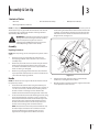
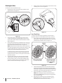
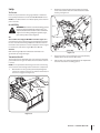
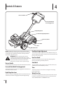
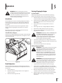
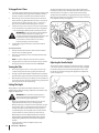
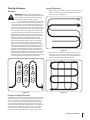
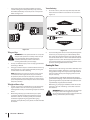
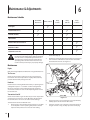
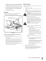
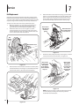
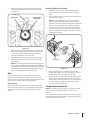
Safe Operation Practices • Set-Up • Operation • Maintenance • Service • Troubleshooting • Warranty
Operator’s Manual
Rear Tine Tiller — Model RT 45
WARNING
READ AND FOLLOW ALL SAFETY RULES AND INSTRUCTIONS IN THIS MANUAL
BEFORE ATTEMPTING TO OPERATE THIS MACHINE.
FAILURE TO COMPLY WITH THESE INSTRUCTIONS MAY RESULT IN PERSONAL INJURY.
CUB CADET LLC, P.O. BOX 361131 CLEVELAND, OHIO 44136-0019
Printed In USA
Form No. 769-10623
(February 6, 2015)
1
To The Owner
Thank You
Thank you for purchasing a Cub Cadet Garden Tiller. It was
carefully engineered to provide excellent performance when
properly operated and maintained.
If applicable, the power testing information used to establish
the power rating of the engine equipped on this machine can be
found at www.opei.org or the engine manufacturer’s web site.
Please read this entire manual prior to operating the equipment.
It instructs you how to safely and easily set up, operate and
maintain your machine. Please be sure that you, and any other
persons who will operate the machine, carefully follow the
recommended safety practices at all times. Failure to do so could
result in personal injury or property damage.
If you have any problems or questions concerning the machine,
phone your local authorized MTD service dealer or contact us
directly. MTD’s Customer Support telephone numbers, website
address and mailing address can be found on this page. We want
to ensure your complete satisfaction at all times.
All information in this manual is relative to the most recent
product information available at the time of printing. Review
this manual frequently to familiarize yourself with the machine,
its features and operation. Please be aware that this Operator’s
Manual may cover a range of product specifications for various
models. Characteristics and features discussed and/or illustrated
in this manual may not be applicable to all models. We reserve
the right to change product specifications, designs and
equipment without notice and without incurring obligation.
Throughout this manual, all references to right and left side of the
machine are observed from the operating position
The engine manufacturer is responsible for all engine-related
issues with regards to performance, power-rating, specifications,
warranty and service. Please refer to the engine manufacturer’s
Owner’s/Operator’s Manual, packed separately with your
machine, for more information.
Table of Contents
Safe Operation Practices......................................... 3
Assembly & Set-Up................................................... 7
Controls & Features.................................................10
Operation.................................................................11
Maintenance & Adjustments..................................16
Service......................................................................18
Troubleshooting..................................................... 20
Replacement Parts..................................................21
Warranty...................................................Back Cover
Record Product Information
Model Number
Before setting up and operating your new equipment, please
locate the model plate on the equipment and record the
information in the provided area to the right. You can locate the
model plate by standing at the operator’s position and looking
down at the rear of the tiller. This information will be necessary,
should you seek technical support via our web site, Customer
Support Department, or with a local authorized service dealer.
Serial Number
Product Registration and Customer Support
Please register your product on our website, www.cubcadet.com.
If you have difficulty assembling this product or have any questions regarding the controls, operation, or maintenance of
this machine, you can seek help from the experts. Choose from the options below:
◊
Visit us on the web at www.cubcadet.com
See How-to Maintenance and Parts Installation Videos at www.cubcadet.com/tutorials
2
◊
Locate your nearest Cub Cadet Dealer at (877) 282-8684
◊
Write to Cub Cadet LLC • P.O. Box 361131 • Cleveland, OH • 44136-0019
2
Important Safe Operation Practices
WARNING! This symbol points out important safety instructions which, if not followed,
could endanger the personal safety and/or property of yourself and others. Read and follow
all instructions in this manual before attempting to operate this machine. Failure to comply
with these instructions may result in personal injury.
When you see this symbol. HEED ITS WARNING!
CALIFORNIA PROPOSITION 65
WARNING! Engine Exhaust, some of its constituents, and certain vehicle components
contain or emit chemicals known to State of California to cause cancer and birth defects
or other reproductive harm.
WARNING! Battery posts, terminals, and related accessories contain lead and lead
compounds, chemicals known to the State of California to cause cancer and reproductive
harm. Wash hands after handling
DANGER! This machine was built to be operated according to the safe operation practices in
this manual. As with any type of power equipment, carelessness or error on the part of the
operator can result in serious injury. This machine is capable of amputating fingers, hands,
toes and feet. Failure to observe the following safety instructions could result in serious
injury or death.
Training
1.
2.
3.
Read, understand, and follow all instructions on the
machine and in the manual(s) before attempting to
assemble and operate. Keep this manual in a safe place for
future and regular reference and for ordering replacement
parts.
Be familiar with all controls and their proper operation.
Know how to stop the machine and disengage them
quickly.
Never allow children under 14 years of age to operate this
machine. Children 14 and over should read and understand
the instructions and safe operation practices in this manual
and on the machine and be trained and supervised by an
adult.
4.
Never allow adults to operate this machine without proper
instruction.
5.
Keep the area of operation clear of all persons, particularly
small children and pets. Stop machine if anyone enters the
area.
Preparation
1.
Thoroughly inspect the area where the equipment is to
be used. Remove all stones, sticks, wire, and other foreign
objects which could be tripped over and cause personal
injury.
2.
Wear sturdy, rough-soled work shoes and close fitting
slacks and shirt. Loose fitting clothes or jewelry can be
caught in moving parts. Never operate this machine in bare
feet or sandals.
3.
Disengage clutch levers and shift (if provided) into neutral
(“N”) before starting the engine.
4.
Never leave this machine unattended with the engine
running.
5.
Never attempt to make any adjustments while engine is
running, except where specifically recommended in the
operator’s manual.
Safe Handling of Gasoline:
To avoid personal injury or property damage use extreme care
in handling gasoline. Gasoline is extremely flammable and the
vapors are explosive. Serious personal injury can occur when
gasoline is spilled on yourself or your clothes which can ignite.
Wash your skin and change clothes immediately.
a.
Use only an approved gasoline container.
b.
Never fill containers inside a vehicle or on a truck
or trailer bed with a plastic liner. Always place
containers on the ground away from your vehicle
before filling.
3
c.
When practical, remove gas-powered equipment
from the truck or trailer and refuel it on the ground.
If this is not possible, then refuel such equipment on
a trailer with a portable container, rather than from a
gasoline dispenser nozzle.
d.
Keep the nozzle in contact with the rim of the fuel
tank or container opening at all times until fueling is
complete. Do not use a nozzle lock-open device.
e.
Extinguish all cigarettes, cigars, pipes and other
sources of ignition.
f.
Never fuel machine indoors.
g.
Never remove gas cap or add fuel while the engine
is hot or running. Allow engine to cool at least two
minutes before refueling.
h.
Never over fill fuel tank. Fill tank to no more than ½
inch below bottom of filler neck to allow space for
fuel expansion.
i.
Replace gasoline cap and tighten securely.
j.
If gasoline is spilled, wipe it off the engine and
equipment. Move unit to another area. Wait 5
minutes before starting the engine.
k.
To reduce fire hazards, keep machine free of grass,
leaves, or other debris build-up. Clean up oil or fuel
spillage and remove any fuel soaked debris.
l.
Never store the machine or fuel container inside
where there is an open flame, spark or pilot light
as on a water heater, space heater, furnace, clothes
dryer or other gas appliances.
Operation
4
1.
Do not put hands or feet near rotating parts. Contact with
the rotating parts can amputate hands and feet.
2.
Do not operate machine while under the influence of
alcohol or drugs.
3.
Never operate this machine without good visibility or light.
Always be sure of your footing and keep a firm hold on the
handles.
4.
11.
After striking a foreign object, stop the engine, disconnect
the spark plug wire and ground against the engine.
Thoroughly inspect the machine for any damage. Repair
the damage before starting and operating.
12. Disengage all clutch levers (if fitted) and stop engine
before you leave the operating position (behind the
handles). Wait until the tines come to a complete stop
before unclogging the tines, making any adjustments, or
inspections.
13.
Never run an engine indoors or in a poorly ventilated area.
Engine exhaust contains carbon monoxide, an odorless
and deadly gas.
14. Muffler and engine become hot and can cause a burn. Do
not touch.
15.
Use caution when tilling near fences, buildings and
underground utilities. Rotating tines can cause property
damage or personal injury.
16. Do not overload machine capacity by attempting to till soil
too deep at too fast of a rate.
17.
If the machine should start making an unusual noise or
vibration, stop the engine, disconnect the spark plug wire
and ground it against the engine. Inspect thoroughly for
damage. Repair any damage before starting and operating.
18. Keep all shields, guards, and safety devices in place and
operating properly.
19.
Never pick up or carry machine while the engine is running.
20.
Use only attachments and accessories approved by the
manufacturer. Failure to do so can result in personal injury.
21.
If situations occur which are not covered in this manual, use
care and good judgement. Contact Customer Support for
assistance and the name of you nearest servicing dealer..
Maintenance & Storage
1.
Keep machine, attachments and accessories in safe
working order.
2.
Keep bystanders away from the machine while it is in
operation. Stop the machine if anyone enters the area.
Allow a machine to cool at least five minutes before
storing. Never tamper with safety devices. Check their
proper operation regularly.
3.
5.
Be careful when tilling in hard ground. The tines may catch
in the ground and propel the tiller forward. If this occurs,
let go of the handle bars and do not restrain the machine.
Check bolts and screws for proper tightness at frequent
intervals to keep the machine in safe working condition.
Also, visually inspect machine for any damage.
4.
6.
Exercise extreme caution when operating on or crossing
gravel surfaces. Stay alert for hidden hazards or traffic. Do
not carry passengers.
Before cleaning, repairing, or inspecting, stop the engine
and make certain the tines and all moving parts have
stopped. Disconnect the spark plug wire and ground it
against the engine to prevent unintended starting.
7.
Never operate the machine at high transport speeds on
hard or slippery surfaces.
5.
8.
Exercise caution to avoid slipping or falling.
Do not change the engine governor settings or over-speed
the engine. The governor controls the maximum safe
operating speed of engine.
9.
Look down and behind and use care when in reverse or
pulling machine towards you.
6.
Maintain or replace safety and instruction labels, as
necessary.
10.
Start the engine according to the instructions found in this
manual and keep feet well away from the tines at all times.
7.
Follow this manual for safe loading, unloading,
transporting, and storage of this machine.
8.
Always refer to the operator’s manual for important details
if the machine is to be stored for an extended period.
Section 2 — Important Safe Operation Practices
9.
If the fuel tank has to be drained, do this outdoors.
10.
Observe proper disposal laws and regulations for gas, oil,
etc. to protect the environment.
11.
According to the Consumer Products Safety Commission
(CPSC) and the U.S. Environmental Protection Agency (EPA),
this product has an Average Useful Life of seven (7) years,
or 130 hours of operation. At the end of the Average Useful
Life have the machine inspected annually by an authorized
service dealer to ensure that all mechanical and safety
systems are working properly and not worn excessively.
Failure to do so can result in accidents, injuries or death.
Notice Regarding Emissions
Engines which are certified to comply with California and federal
EPA emission regulations for SORE (Small Off Road Equipment)
are certified to operate on regular unleaded gasoline, and
may include the following emission control systems: Engine
Modification (EM), Oxidizing Catalyst (OC), Secondary Air
Injection (SAI) and Three Way Catalyst (TWC) if so equipped.
Spark Arrestor
WARNING! This machine is equipped with an
internal combustion engine and should not be used
on or near any unimproved forest-covered,
brushcovered or grass-covered land unless the
engine’s exhaust system is equipped with a spark
arrestor meeting applicable local or state laws (if
any).
If a spark arrestor is used, it should be maintained in effective
working order by the operator. In the State of California the
above is required by law (Section 4442 of the California Public
Resources Code). Other states may have similar laws. Federal laws
apply on federal lands.
A spark arrestor for the muffler is available through your
nearest engine authorized service dealer or contact the service
department, P.O. Box 361131 Cleveland, Ohio 44136-0019.
Section 2 — Important Safe Operation Practices
5
Safety Symbols
This page depicts and describes safety symbols that may appear on this product. Read, understand, and follow all instructions on the
machine before attempting to assemble and operate.
Symbol
Description
READ THE OPERATOR’S MANUAL(S)
Read, understand, and follow all instructions in the manual(s) before attempting to
assemble and operate
WARNING— ROTATING TINES
Do not put hands or feet near rotating parts. Contact with the rotating parts can amputate
hands and feet.
WARNING— ROTATING TINES
Do not put hands or feet near rotating parts. Contact with the rotating parts can amputate
hands and feet.
WARNING—GASOLINE IS FLAMMABLE
Allow the engine to cool at least two minutes before refueling.
WARNING— CARBON MONOXIDE
Never run an engine indoors or in a poorly ventilated area. Engine exhaust contains carbon
monoxide, an odorless and deadly gas.
WARNING— HOT SURFACE
Engine parts, especially the muffler, become extremely hot during operation. Allow engine
and muffler to cool before touching.
WARNING! Your Responsibility—Restrict the use of this power machine to persons who read, understand and
follow the warnings and instructions in this manual and on the machine.
SAVE THESE INSTRUCTIONS!
6
Section 2 — Important Safe Operation Practices
3
Assembly & Set-Up
Contents of Carton
•
One Tiller
•
One Engine Operator’s Manual
•
One Handlebar Assembly
NOTE: This Operator’s Manual covers several models. Garden
Tiller features may vary by model. Not all features in this manual
are applicable to all garden tiller models and the garden tiller
depicted may differ from yours.
3.
WARNING! To prevent personal injury or property
damage, do not start the engine until all assembly
steps are complete and you have read and
understand the Safe Operation Practices Section
and the Operating Section in this manual.
•
One Operator’s Manual
Install the handle-crank adjustment rod into the top hole of
the mounting bracket from the left hand side of the handle
assembly, secure with the other flange lock nut previously
removed. Fit the hex end of the retainer bracket over the
flange lock nut. See Figure 3-1.
Assembly
Unpacking Instructions
NOTE: While unpacking, do not severely bend any of the control
cables.
1.
The tiller is heavy, do not attempt to remove it from
the shipping platform until instructed to do so in these
assembly steps.
2.
Remove all parts from the carton. Check that you have the
items listed in the Contents of Carton list (contact your
local dealer or the MTD technical service representative if
items are missing or damaged).
3.
Remove any packaging material from the carton. Remove
any staples from the bottom of the carton and remove the
carton from the shipping platform.
Figure 3-1
Handle
4.
NOTE: All references to the right or left side of the tiller are from
the operator’s position.
Tighten the hex bolt installed in Step 2 at this time. Be
careful not to overtighten this hardware.
5.
With the handle in the desired position, tighten the handlecrank adjustment rod at this time.
1.
Install the handle onto the tiller using the hardware preinstalled on the handle mounting brackets. This consists of
a 5⁄16-18 x 3.00 hex bolt, a handle crank assembly, retainer
bracket and two 5⁄16-18 flange lock nuts. Remove this
hardware from the handle mounting brackets on the tiller.
2.
Insert the handle into the handle mounting brackets, lining
up the pre-drilled holes. Insert the 5⁄16-18 x 3.00 hex bolt
in the bottom hole from the left hand side through to the
other side. Place the round hole end of the hex retainer
bracket over the hex bolt and secure loosely with a bell
washer and 5⁄16-18 flange lock nut removed earlier.
NOTE: The bell washer should be positioned with the top
of the bell shape towards the hex nut which will create
tension and further secure the flange lock nut once
tightened. Do not tighten this hardware at this time.
7
Attaching the Cables
5.
To attach the cables, follow these steps:
1.
Clip the cables into the cable guides located on the handle
assembly panel as seen in Figure 3-3.
Route the two cables along the handle assembly on the
right-hand side. See Figure 3-2.
Black
Red
Red
Black
Figure 3-3
Move Tiller Off Crate
Figure 3-2
2.
Connect the reverse cable (Red) to the reverse cable
control by feeding the z-hook through the hole on the
reverse cable control from the inside towards the outside.
Refer to Figure 3-2.
3.
Connect the forward drive cable (Black) to the clutch bail
by feeding the z-hook through the hole on the clutch bail
from the outside towards the inside. See Figure 3-2.
To roll the tiller off the shipping platform, put the wheels in
freewheel, if they are not already from the factory, as follows:
1.
Place a sturdy block under the transmission to raise one
wheel about 1” off the ground. Remove the click pin from
the wheel hub and wheel shaft. See Figure 3-4.
Click Pin
NOTE: Test the function of the reverse clutch and forward
drive bail by pulling the reverse handle and releasing it. The
handle should return to its neutral position. If it doesn’t,
contact your local dealer for technical assistance.
To Test the function of the forward drive bail, lift the bail
to the handle and release it. The bail should return to its
neutral position. If it doesn’t, contact your local dealer for
technical assistance.
4.
Snap the cable housing clips into the handle assembly
cable mount as seen here. The red clip (reverse cable)
fits into the top position on the handle assembly, while
the black clip (forward/clutch cable) feeds into the lower
position on the handle assembly. See Figure 3-2.
Remove the click pin
from the wheel hub
Slide the wheel fully
inward on the wheel
shaft . Reinstall the
click pin
Figure 3-4
2.
Slide the wheel fully inward on the wheel shaft . Reinstall
the click pin through the wheel shaft only (not through the
wheel hub). See Figure 3-4. The wheel should now spin freely
(freewheel) on the wheel shaft. Repeat with the other wheel.
3.
Use the handlebar to roll the tiller to a flat area.
NOTE: Before starting the engine, the wheels must be
placed in the WHEEL DRIVE position (pins through wheel
hubs and wheel shaft).
4.
8
Section 3 — Assembly & Set-Up
Once the tiller is off the crate, place the wheels in the
WHEEL DRIVE position, remove the click pin, slide the
wheel fully inward and reinstall the click pin.
Set-Up
2.
Tire Pressure
Remove the oil fill plug from the transmission housing
cover and locate the main drive shaft situated inside the
housing. See Figure 3-6.
Check the air pressure with a tire gauge. Deflate or inflate the
tires equally to between 15 and 20 PSI. DO NOT EXCEED 20 P.S.I.
NOTE: Be sure that both tires are inflated equally or the tiller will
pull to one side.
Gas & Oil Fill Up
WARNING! Use extreme care when handling gasoline.
Gasoline is extremely flammable and the vapors are
explosive. Never fuel the machine indoors or while the
engine is hot or running. Extinguish cigarettes, cigars,
pipes and any other sources of ignition.
Oil
This machine was shipped WITHOUT oil in the engine. Oil is
included in the plastic literature bag packed with the tiller. Add
the oil as instructed in the Engine Operator’s Manual. Check oil
level before each operation to ensure adequate oil in the engine.
For instructions, refer to the Engine Operator’s Manual.
Gasoline
Refer to the Engine Operator’s Manual for information on
gasoline fill-up and gasoline type.
Transmission/Gear Oil
The transmission was filled with gear oil at the factory. However,
you should check the gear oil level at this time to make certain it
is correct.
Figure 3-6
3.
The gear oil level is correct if the gear oil is approximately
halfway up the side of the main drive shaft.
4.
If the oil level is low, refer to the Maintenance & Adjustments
section for instructions on adding gear oil.
NOTE: Do not operate the tiller if the gear oil level is low. Doing
so will result in severe damage to the transmission components.
1.
With the tiller on level ground, pull the Depth Regulator
Lever back and then all the way up until the lowest notch in
the lever is engaged. See Figure 3-5.
Depth Regulator
Lever
Figure 3-5
Section 3 — Assembly & Set-Up
9
4
Controls & Features
Reverse Handle
Forward Clutch Bail
& Tine Engagement
Depth Regulator
Handle Height Adjustment
Rear Tine Shield
Side Shield
Tines
Wheel Drive Pin
NOTE: This Operator’s Manual covers several models. Garden
Tiller features may vary by model. Not all features in this manual
are applicable to all garden tiller models and the garden tiller
depicted may differ from yours.
WARNING! Before operating your machine,
carefully read and understand all safety, controls
and operating instructions in this manual and on the
decals on the machine. Failure to follow these
instructions can result in serious personal injury.
Reverse Handle
The Reverse Handle controls the reverse drive of the wheels and tines.
Forward Clutch Bail & Tine Engagement
The forward clutch bail controls the engagement of the forward
drive of the wheels and tines.
Depth Regulator Lever
This lever controls the tilling depth of the tines. Pull the lever back
and slide it up or down to engage the notched height settings.
10
Handlebar Height Adjustment
The handlebar height is adjustable to three different settings. In
general, adjust the handlebars so they are at waist level when the
tines are 3-4” in the ground.
Rear Tine Shield
The rear tine shield protects the operator from flying debris
while also smoothing out freshly tilled soil.
Side Shield
The side shield is used to maintain clear even rows and may be
adjusted to one of five different positions.
Tines
Your tiller’s tines are a series of hoes arranged on a revolving
power-driven shaft.
Wheel Drive Pins
Each wheel is equipped with a wheel drive click pin that secures
the wheel to the wheel shaft. The wheels can be positioned in
either a WHEEL DRIVE or a FREEWHEEL mode.
5
Operation
WARNING: Before operating your machine,
carefully read and understand this manual and all of
its safety, operating and maintenance sections and
instructions, along with all of the decals on the
machine. Failure to follow these instructions can
result in serious personal injury.
Starting & Stopping the Engine
Pre-Start Checklist
With the spark plug wire disconnected from the spark plug,
perform the following checks and services before each use:
1.
Read the Safety Section in this manual. Read the Controls
Section in this manual. Read the Engine Operator’s Manual.
2.
Put the wheels in the WHEEL DRIVE position (wheel pins
must be through the holes in the wheel hubs and the
wheel shaft).
3.
Find an open, level area and practice using the tiller controls
without the tines engaging the soil (put tines in “transport”
setting).
Check unit for loose or missing hardware. Service as
required.
4.
Check engine oil level. See Engine Operator’s Manual.
5.
Check that all safety guards and covers are in place.
Only after you’ve become completely familiar with the tiller
should you begin using it in the garden.
6.
Check air cleaner and engine cooling system. See the
Engine Operator’s Manual.
Introduction
Read this Operation Section and the Engine Operator’s Manual
before you start the engine. Then, take the time to familiarize
yourself with the basic operation of the tiller before using it in
the garden.
To Put The Tines in Transport:
WARNING! GASOLINE IS HIGHLY FLAMMABLE AND
ITS VAPORS ARE EXPLOSIVE. Follow the gasoline
safety rules in the Important Safe Operation
Practices section of this manual. Failure to follow
gasoline safety instructions can result in serious
personal injury and property damage.
Pull back on the depth adjustment bracket (A) and push down (B)
until the bracket reaches the highest notch. See Figure 5-1. Then
release the bracket (C).
C
A
B
7.
Fill the fuel tank with gasoline according to the directions
in the Engine Operator’s Manual. Follow all instructions and
safety rules carefully.
8.
Attach the spark plug wire to the spark plug.
Starting & Stopping the Engine
WARNING! To help prevent serious personal injury
or damage to equipment, put both wheels in the
WHEEL DRIVE position. Never have wheels in
FREEWHEEL position when the engine is running.
When the wheels are in FREEWHEEL, they do not
hold back the tiller and the tines could propel the
tiller rapidly forward or backward. Put the Forward
Clutch Bail in the neutral (disengaged) position by
releasing the lever.
WARNING! Never run the engine indoors or in an
enclosed, poorly ventilated area. Engine exhaust
contains carbon monoxide, an odorless and deadly
gas. Avoid the engine muffler and nearby areas.
Temperatures in these areas may exceed 150° F.
Figure 5-1
Break-In Operation
1.
Complete the Pre-Start Checklist above on this page.
Perform the following maintenance after the first five (5) hours
of new operation (see the Maintenance & Adjustments Section in
this manual).
2.
Put the wheels in the WHEEL DRIVE position by removing
the click pins, sliding the wheel all the way in and reinstalling
the click pin through the wheel hubs and wheel shaft.
1.
Change engine oil.
3.
2.
Check for loose or missing hardware on unit. Tighten or
replace as needed.
Move the Depth Regulator Lever all the way down to the
“transport” position, so that the tines clear the ground.
4.
3.
Check transmission gear oil level.
Release all of the controls on the tiller and refer the Engine
Operator’s Manual for engine starting and stopping
instructions.
11
To Engage Drive & Tines
1.
For forward motion of the wheels and power to the tines pull
the Forward Clutch Bail up against the handlebar. Release
the bail to stop the forward motion of wheels and tines.
2.
When tilling, relax and let the wheels pull the machine
while the tines dig. Walk behind and a little to one side of
the tiller. Use one hand, yet keep a light — but secure —
grip on the handlebar while keeping your arm loose.
3.
Let the tiller move at its own pace and do not push down
on the handlebars to try and force the tines to dig deeper
— this takes weight off the wheels and reduces traction.
To adjust the depth stake, pull back on the depth adjustment
bracket (A) and push up or down (B) until the bracket reaches the
desired position, see Figure 5-1, then release the bracket (C).
To adjust the side shields (if so equipped), remove the wing nuts.
Move the side shield to the desired position and replace the wing
nuts. Tighten securely. See Figure 5-2.
WARNING! Do not push down on the handlebars
to try to make the tiller till more deeply. This
prevents the wheels from holding the tiller back and
can allow the tines to rapidly propel the tiller
forward, which could result in loss of control,
property damage, or personal injury.
4.
To stop/disengage the drive/tines release the forward
clutch bail.
To move in reverse:
1.
Release the forward Clutch Bail. Then lift the handlebar
until the tines are off the ground.
2.
Pull back on the Reverse Lever, and walk backwards with
the machine
NOTE: In reverse mode, the tines will reverse rotation.
3.
If longer distances need to be covered in reverse, shut off
the engine, then place the two wheels in FREEWHEEL.
Turning the Tiller
1.
Practice turning the tiller in a level, open area. Be very
careful to keep your feet and legs away from the tines.
2.
To begin a turn, lift the handlebars until the tines are out of the
ground and the engine and tines are balanced over the wheels.
3.
With the tiller balanced, push sideways on the handlebar to
steer in the direction of the turn. After turning, slowly lower
the tines into the soil to resume tilling.
Figure 5-2
Adjusting the Handle Height
The handle should be adjusted so that when the tiller is digging
3-4” into the soil, the handle falls to about waste-high. To adjust
the handle, simply loosen the handle adjustment crank, move
the handle to the desired height and retighten the adjustment
crank. See Figure 5-3.
Setting The Depth
Tilling depth is controlled by the depth stake which can be
adjusted to five different settings. Adjust the side shields as you
adjust the depth stake.
WARNING: Be certain the spark plug wire is
disconnected and grounded against the engine
when performing any adjustments.
12
•
When using the tiller for the first time, use the second
adjustment hole from the top (1” of tilling depth).
•
When breaking up sod and for shallow cultivation, use the
setting which gives 1” of tilling depth (second hole from
the top). Place the side shields in their lowest position.
•
For further depth, raise the depth stake and side shields
and also make one or two more passes over the area.
•
When tilling loose soil, the depth stake may be raised to its
highest position (use bottom adjustment hole) to give the
deepest tilling depth. Raise the side shields to the highest
position.
•
To transport tiller, lower the depth stake (use top
adjustment hole).
Section 5— Operation
Figure 5-3
Tilling Tips & Techniques
Suggested Tilling Patterns
Tilling Depth
•
WARNING! Before tilling, contact your telephone or
When preparing a seedbed, go over the same path twice in
the first row, then overlap one-half the tiller width on the
rest of the passes. See Figure 5-5.
utilities company and inquire if underground equipment/
lines are used on your property. Do not till near buried
electric cables, telephone lines, pipes or hoses.
•
This is a CRT (counter-rotating tine) tiller. As the
wheels pull forward, the tines rotate backward. This creates
an “uppercut” tine action which digs deeply, uprooting soil
and weeds. Don’t overload the engine, but dig as deeply as
possible on each pass. On later passes, the wheels may tend
to spin in the soft dirt. Help them along by lifting up slightly
on the handlebar (one hand, palm up, works most easily).
•
Avoid the temptation to push down on the handlebars in an
attempt to force the tiller to dig deeper. Doing so takes the
weight off the powered wheels, causing them to lose traction.
Without the wheels to hold the tiller back, the tines will
attempt to propel the tiller backward, towards the operator.
•
When cultivating (breaking up the surface soil around the
plants to destroy weeds, see Figure 5-4), adjust the tines to
dig only 1” to 2” deep. Using the shallow tilling depth helps
prevent injury to the plants whose roots often grow close to
the surface. If needed, lift up on the handlebars slightly to
prevent the tines from digging too deeply. (Cultivating on a
regular basis not only eliminates weeds, it also loosens and
aerates the soil for better moisture absorption and faster plant
growth.) Watering the garden area a few days prior to tilling
will make tilling easier, as will letting the newly worked soil set
for a day or two before making a final, deep tilling pass.
Figure 5-4
Figure 5-5
•
When finished in one direction, make a second pass at a
right angle, as shown in Figure 5-6. Overlap each pass for
the best results (in very hard ground, it may take three or
four passes to thoroughly pulverize the soil.)
Figure 5-6
Choosing Correct Wheel & Tine Speeds
With experience, you will find the tilling depth and tilling speed
combination that is best for your garden. Set the engine throttle
lever at a speed to give the engine adequate power and yet
allow it to operate at the slowest possible speed until you have
achieved the maximum tilling depth you desire. Faster engine
speeds may be desirable when making final passes through the
seedbed or when cultivating. Selection of the correct engine
speed, in relation to the tilling depth, will ensure a sufficient
power level to do the job without causing the engine to labor.
Section 5 — Operation
13
•
If the garden size will not permit lengthwise and then
crosswise tilling, then overlap the first pass by one-half a
tiller width, followed by successive passes at one-quarter
width. See Figure 5-7.
Terrace Gardening
1.
To create a terrace, start at the top of the slope and work
down. Go back and forth across the first row as shown in
Figure 5-8.
UPHILL
1
1
2
2
3
12" UNTILLED
3
1
REPEAT
DOWNHILL
Figure 5-7
Tilling on a Slope
Figure 5-8
2.
WARNING! Do not operate the tiller on a slope too
steep for safe operation. Till slowly and be sure you
have good footing. Never permit the tiller to
freewheel down slopes. Failure to follow this
warning could result in personal injury.
1.
Till only on moderate slopes, never on steep ground where
the footing is difficult.
2.
Tilling up and down slopes is recommended over terracing.
Tilling vertically on a slope allows maximum planting area
and also leaves room for cultivating.
NOTE: When tilling on slopes, be sure the correct oil level
is maintained in the engine (check every one-half hour
of operation). The incline of the slope will cause the oil to
slant away from its normal level and this can starve engine
parts of required lubrication. Keep the motor oil level at the
full point at all times.
Tilling Up and Down a Slope
1.
2.
14
To keep soil erosion to a minimum, be sure to add enough
organic matter to the soil so that it has good moistureholding texture and try to avoid leaving footprints or wheel
marks.
When tilling vertically, try to make the first pass uphill
as the tiller digs more deeply going uphill than it does
downhill. In soft soil or weeds, you may have to lift the
handlebars slightly while going uphill. When going
downhill, overlap the first pass by about one-half the width
of the tiller.
Section 5— Operation
Each succeeding lower terrace is started by walking below
the terrace you are preparing. For added stability of the
tiller, always keep the uphill wheel in the soft, newly tilled
soil. Do not till the last 12” or more of the downhill outside
edge of each terrace. This untilled strip helps prevent the
terraces from breaking apart and washing downhill. It also
provides a walking path between the rows.
Clearing the Tines
•
The tines have a self-clearing action which eliminates most
of the tangling of debris. However, occasionally dry grass,
stringy stalks or tough vines may become tangled. Follow
these procedures to help avoid tangling and to clear the
tines, if necessary.
•
To reduce tangling, set the depth regulator deep enough to
get maximum “chopping” action as the tines chop the material
against the ground. Also, try to till under crop residues or cover
crops while they are green, moist and tender.
•
While tilling, try swaying the handlebars from side to side
(about 6” to 12”). This “fishtailing” action often clears the
tines of debris.
WARNING! Before clearing the tines by hand, stop
the engine, allow all moving parts to stop and
disconnect the spark plug wire. Failure to follow this
warning could result in personal injury.
Loading & Unloading the Tiller
WARNING! Loading and unloading the tiller into a
vehicle is potentially hazardous and doing so is not
recommended unless absolutely necessary, as this
could result in personal injury or property damage.
However, if you must load or unload the tiller, follow the
guidelines given next.
•
Before loading or unloading the tiller, stop the engine, wait
for all parts to stop moving, disconnect the spark plug wire
and let the engine and muffler cool.
•
The tiller is too heavy and bulky to be safely lifted by one
person. Two or more people should share the load.
•
Use sturdy ramps and manually — with the engine shut
off — roll the tiller into and out of the vehicle. Two or more
people are needed to do this.
•
The ramps must be strong enough to support the
combined weight of the tiller and any handlers. The ramps
should provide good traction to prevent slipping; they
should also have side rails to guide the tiller along the
ramps; and they should have a locking device to secure
them to the vehicle.
•
The handlers should wear sturdy footwear that will help to
prevent slipping.
•
Position the loading vehicle so that the ramp angle is as flat
as possible (the less incline to the ramp, the better). Turn
the vehicle’s engine off and apply the parking brake.
•
When going up the ramps, stand in the normal operating
position and push the tiller ahead of you. Have a person at
each side to turn the wheels.
•
When going down the ramps, walk backward with the tiller
following you. Keep alert for any obstacles behind you.
Position a person at each wheel to control the speed of the
tiller. Never go down the ramps tiller-first, as the tiller could
tip forward.
•
Place wooden blocks on the downhill side of the wheels
if you need to stop the tiller from rolling down the ramp.
Also, use the blocks to temporarily keep the tiller in place
on the ramps (if necessary), and to chock the wheels in
place after the tiller is in the vehicle.
•
After loading the tiller, prevent it from rolling by engaging
the wheels in the WHEEL DRIVE position. Chock the wheels
with blocks and securely tie the tiller down.
Section 5 — Operation
15
6
Maintenance & Adjustments
Maintenance Schedule
Check After
first 2 hours
Before each use
Every
5 Hours
Every
10 Hours
Every
30 Hours
P
Clean Engine
Check Drive Belt Tension
Check Nuts and Bolts
P
P
P
P
P
Lubricate Tiller
P
P
P
Check Gear Oil Level in Transmission
Check Tines for Wear
Check Air Pressure in Tires
WARNING! Before inspecting, cleaning or servicing
the machine, shut off the engine, wait for all moving
parts to come to a complete stop, disconnect the
spark plug wire and move the wire away from the
spark plug. Failure to follow these instructions can
result in serious personal injury or property damage.
2.
With the tiller on level ground, pull the Depth Regulator
Lever all the way up.
3.
Remove the oil fill plug from the transmission housing and
look inside the oil fill hole to locate the main drive shaft
situated below the hole. See Figure 6-1.
4.
The gear oil level is correct if the gear oil is approximately
halfway up the side of the main drive shaft.
5.
If the gear oil level is low, add gear oil as described next. If
the gear oil level is okay, securely replace the oil fill plug.
Maintenance
Engine
Refer to the Engine Operator’s Manual for all engine maintenance.
Tire Pressure
Check the air pressure in both tires. The air pressure should
be between 15-20 PSI. Keep both tires equally inflated to help
prevent machine from pulling to one side.
Hardware
Check for loose or missing hardware after every 10 operating hours
and tighten or replace — as needed — before reusing the tiller
Be sure to check the screws underneath the tiller hood that
secure the transmission cover and the Depth Regulator Lever to
the transmission.
Transmission Gear Oil
Check the transmission gear oil after every 30 hours of operation
or whenever you notice any oil leak. Operating the tiller when
the transmission is low on oil can result in severe damage.
Figure 6-1
To Check the Transmission Gear Oil Level:
1.
16
Check the gear oil level when the transmission is cool. Gear
oil will expand in warm operating temperatures and this
expansion will provide an incorrect oil level reading.
6.
7.
8.
If adding only a few ounces of gear oil, use API rated GL-4
or GL-5 gear oil having a viscosity of SAE 140, SAE 85W-140
or SAE 80W-90. If refilling an empty transmission, use only
GL-4 gear oil having a viscosity of SAE 85W-140 or SAE 140.
Off-Season Storage
While checking frequently to avoid overfilling, slowly add
gear oil into the oil fill hole until it reaches the halfway
point on the drive shaft.
1.
Clean the tiller and engine.
2.
Do routine tiller lubrication and check for loose parts and
hardware.
Securely replace the oil fill plug.
3.
Change the engine oil and filter following the instructions
provided in the engine manual packed with this manual.
When the tiller won’t be used for an extended period, prepare it
for storage as follows:
Lubrication
WARNING! Never store the tiller with fuel in the
tank indoors or in poorly ventilated enclosures, where
fuel fumes may reach an open flame, spark or pilot
light as on a furnace, water heater, clothes dryer, etc.
After every 10 operating hours, oil or grease the lubrication
points shown in Figure 6-2 and described below.
4.
If storing the tiller for 30 days or more:
a.
Depth Regulator Lever
Handlebar Hardware
To prevent gum deposits from forming inside
the engine’s carburetor and causing possible
malfunction of the engine, the fuel system must be
either completely emptied, or the gasoline must be
treated with a stabilizer to prevent deterioration.
WARNING! Fuel left in the fuel tank deteriorates
and will cause serious starting problems.
b.
Wheel Shaft
Tine Shaft
Figure 6-2
Use clean lubricating oil (#30 weight motor oil is suitable)
and clean general purpose grease (grease containing a metal
lubricant is preferred, if available).
•
Remove the wheels, clean the wheel shaft and apply a thin
coating of grease.
•
Grease the back, front and sides of the depth regulator lever.
•
Remove the tines and clean the tine shaft. Use a file or
sandpaper to gently remove any rust, burrs or rough spots
(especially around the holes in the shaft). Apply grease to
the ends of the shaft before installing the tines.
•
Oil the threads on the handlebar height adjustment screws
and the handlebar attaching screws.
c.
Using a fuel stabilizer such as STA-BIL® for storage
between 30 and 90 days:
•
Read the product manufacturer’s instructions
and recommendations.
•
Add to clean, fresh gasoline the correct
amount of stabilizer for the capacity
(approximately 3 gallons) of the fuel system.
•
Fill the fuel tank with treated fuel and run the
engine for 2-3 minutes to get stabilized fuel
into the carburetor.
Emptying the fuel system for storage of more than
90 days:
•
Prior to putting the tiller in storage, monitor
fuel consumption with the goal of running
the fuel tank empty.
•
Run the engine until it begins to stall. Use the
choke to keep the engine running until all fuel
in the carburetor has been exhausted.
•
Referring to the engine manual, drain the fuel
from the carburetor bowl.
4.
Store the tiller in a clean, dry area.
5.
Never store the tiller with fuel in the fuel tank in an
enclosed area where gas fumes could reach an open flame
or spark, or where ignition sources are present (space
heaters, hot water heaters, furnaces, etc.).
Section 6 — Maintenance & Adjustments
17
7
Service
Belt Replacement
4.
If the drive or reverse belts need to be replaced, it is best to replace
both belts at the same time. Use only a factory-authorized belt as an
“over- the-counter” belt may not perform satisfactorily. The procedure
requires average mechanical ability and commonly available tools.
To replace the drive and reverse belts, follow these steps:
1.
Make sure the tiller is on a flat surface, with the engine
turned off and the spark plug wire unplugged and
grounded to prevent unintended firing of the engine.
2.
Remove the belt cover as seen in Figure 7-1, by first
removing the two 1⁄4-20 hex washer screws and one flat
washer. Lift the belt cover up and away from the tiller and
set in a safe location until reinstallation.
Remove the idler bracket extension spring, as pointed out in
Figure 7-3. It is recommended to use a pair of needle-nosed
pliers, and grab the spring by the end that hooks over the
frame. Simply grab it and pull it away from the frame, then
up wards and carefully relieve the tension of the spring.
Remove the
idler bracket
extension
spring
This belt should
be installed with
the V-side out
Hex
Washer
Screw
Hex Washer Screw
Flat Washer
Figure 7-3
5.
Figure 7-1
3.
Remove the four 1⁄4-20 hex washer screws that secure the pulley
shield to the frame as seen in Figure 7-2, and remove the pulley
shield and set aside in a safe location until reinstallation.
Remove the idler pulley bracket by removing the 5⁄16-24 hex
screw, flat washer and lock washer, as in Figure 7-4.
Remove the
idler pulley
bracket by
removing the
hex screw,
flat and lock
washers
Remove the
belt from the
idler pulley
by working it
under the belt
keepers.
Figure 7-4
NOTE: It will be necessary to remove the belt from around
the idler pulley by working it off the pulley and from
underneath each belt keeper.
Hex Washer
Screw
18
Figure 7-2
6.
Remove the flange nut securing the transmission drive
pulley, then remove the pulley along with the two belts.
See Figure 7-5.
Removing/Installing a Tine Assembly
1.
Remove the tine shield end covers and side shields by
removing the three wing nuts on each side that secure
them.
2.
A tine assembly consists of a left hand tine assembly and a
right hand tine assembly.
V-side out
Remove pulley
with belts
Flange Nut
NOTE: The tine assembly moves in a counter-rotating
motion with the sharp edges of the tines positioned to
enter the soil first when counter-rotating. Note this position
of the tines for reinstallation of the new tine assemblies.
3.
To remove a tine assembly, simply remove the cotter pin
securing the clevis pin as seen in Figure 7-6. Remove the
clevis pin and slide the assembly to the outside of the unit
and off of the tine shaft.
Clevis Pin
Figure 7-5
7.
Replace the old belts with the new belts in the same order
they were removed. The longer belt (954-04091) belongs
closer to the engine (V-side out), with the shorter belt
(954-04090) positioned closer to the tines.
8.
Reinstall the transmission drive pulley with the new belts.
9.
Reassemble the tiller in the reverse order in which it was
disassembled.
NOTE: When reinstalling the belt cover, be sure to engage the
bail and hold it so that the drive belt is tight before attempting
to reinstall the belt cover. This will enable the belt to fall under
the belt keeping mechanism built into the belt cover. Failure
to do so could damage the belt and/or belt cover.
Tines
The tines will wear with use and should be inspected at the
beginning of each tilling season and after every 30 operating
hours. The tines can be replaced. Refer to the Illustrated Parts List
manual for part numbers and ordering instructions.
Tine Inspection
With use, the tines will become shorter, narrower and pointed.
Badly worn tines will result in a loss of tilling depth, and reduced
effectiveness when chopping up and turning under organic
matter.
Cotter Pin
Figure 7-6
4.
Before reinstalling the tine assembly, inspect the tine
shaft for rust, rough spots or burrs. Lightly file or sand, as
needed. Apply a thin coat of grease to the shaft.
5.
Install each tine assembly so that the cutting (sharp) edge
of the tines will enter the soil first when the tiller moves
forward. Keep in mind that these tines are counter rotating,
so secure the tine assembly to the tine shaft using the
clevis pin and internal cotter pin.
Change Transmission Gear Oil
NOTE: The transmission gear oil does not need to be changed
unless it has been contaminated with dirt, sand or metal
particles.
See an authorized service dealer to have the transmission gear oil
changed. Refer to the phone numbers on page 2 of this manual
to locate the nearest service dealer.
Section 7 — Service
19
8
Troubleshooting
Problem
Wheels/Tines will not turn
Tines turn, but wheels don’t
Wheels turn, but tines Don’t
Poor tilling performance
20
Cause
Remedy
1. Improper use of controls.
1. Review Operation section.
2. Worn, broken, or misadjusted drive belt(s).
2. Replace or adjust belts.
3. Internal transmission wear or damage.
3. Contact authorized service dealer.
4. Bolt loose in transmission pulley.
4. Tighten bolt.
1. Wheel Drive Pins not in WHEEL DRIVE.
1. Inserts Drive Pins properly.
2. Bolt loose in transmission pulley.
2. Tighten bolt.
3. Internal transmission wear or damage.
3. Contact authorized service dealer.
1. Tine holder mounting hardware missing.
1. Replace hardware.
2. Bolt loose in transmission pulley.
2. Tighten bolt.
3. Internal transmission wear or damage.
3. Contact authorized service dealer.
1. Worn tines.
1. Replace Tines.
2. Improper Depth Regulator setting.
2. See “Tilling Tips & Techniques.”
3. Incorrect throttle setting.
3. See Maintenance & Adjustments Section.
4. Forward Drive Belt slipping.
4. See Maintenance & Adjustments Section.
9
Replacement Parts
Component
Part Number and Description
954-04090
954-04091
Reverse V-Belt
Forward V-Belt
946-04506
946-04504
Forward Drive Cable
Reverse Drive Cable
642-04072
642-04071
911-0415
714-04043
4-Point Tine Assembly (RH)
4-Point Tine Assembly (LH)
Clevis Pin, .375 x 1.75
Internal Cotter Pin
934-04736
Wheels, 13 x 5 x 6
714-0143A
Click Pin, .25 x 1.56
21
Notes
22
10
Section 10 — Notes
23
CUB CADET LLC
MANUFACTURER’S LIMITED WARRANTY FOR
EDGERS, STRING TRIMMERS & TILLERS
The limited warranty set forth below is given by Cub Cadet LLC
with respect to new merchandise purchased and used in the United
States, its possessions and territories, and by MTD Products Limited
with respect to new merchandise purchased and used in Canada
and/or its territories and possessions.
c.
Cub Cadet does not extend any warranty for products sold
or exported outside of the United States and/or Canada, and
their respective possessions and territories, except those
sold through Cub Cadet’s authorized channels of export
distribution.
This warranty is in addition to any applicable emissions warranty
provided with your product.
d.
Replacement parts that are not genuine Cub Cadet parts.
e.
Service completed by someone other than an authorized
service dealer.
f.
Transportation charges and service calls.
g.
Cub Cadet does not warrant this product for commercial use.
“Cub Cadet” warrants this product (excluding its Normal Wear Parts
as described below) against defects in material and workmanship
for a period of three (3) years commencing on the date of original
purchase and will, at its option, repair or replace, free of charge,
any part found to be defective in materials or workmanship. This
limited warranty shall only apply if this product has been operated
and maintained in accordance with the Operator’s Manual
furnished with the product, and has not been subject to misuse,
abuse, commercial use, neglect, accident, improper maintenance,
alteration, vandalism, theft, fire, water, or damage because of other
peril or natural disaster. Damage resulting from the installation
or use of any part, accessory or attachment not approved by Cub
Cadet for use with the product(s) covered by this manual will void
your warranty as to any resulting damage.
Normal Wear Parts are warranted to be free from defects in material
and workmanship for a period of thirty (30) days from the date of
purchase. Normal wear parts include, but are not limited to items
such as: batteries, belts, blades, tines, wheels and tires.
HOW TO OBTAIN SERVICE: Warranty service is available, WITH
PROOF OF PURCHASE, through your local authorized service dealer.
To locate the dealer in your area:
In the U.S.A.
To locate the dealer in your area, check your Yellow Pages, or
contact Cub Cadet LLC at P.O. Box 361131, Cleveland, Ohio 441360019, or call 1-877-282-8684, or log on to our Web site at www.
cubcadet.com.
In Canada
Contact MTD Products Limited, Kitchener, ON N2G 4J1, or call
1-800-668-1238 or log on to our Web site at www.mtdcanada.com.
This limited warranty does not provide coverage in the following
cases:
No implied warranty, including any implied warranty of
merchantability of fitness for a particular purpose, applies
after the applicable period of express written warranty above
as to the parts as identified. No other express warranty,
whether written or oral, except as mentioned above, given by
any person or entity, including a dealer or retailer, with respect
to any product, shall bind Cub Cadet. During the period of the
warranty, the exclusive remedy is repair or replacement of the
product as set forth above.
The provisions as set forth in this warranty provide the sole
and exclusive remedy arising from the sale. Cub Cadet shall
not be liable for incidental or consequential loss or damage
including, without limitation, expenses incurred for substitute
or replacement lawn care services or for rental expenses to
temporarily replace a warranted product.
Some states do not allow the exclusion or limitation of incidental
or consequential damages, or limitations on how long an implied
warranty lasts, so the above exclusions or limitations may not apply
to you.
In no event shall recovery of any kind be greater than the amount
of the purchase price of the product sold. Alteration of safety
features of the product shall void this warranty. You assume
the risk and liability for loss, damage, or injury to you and your
property and/or to others and their property arising out of the
misuse or inability to use the product.
This limited warranty shall not extend to anyone other than the
original purchaser or to the person for whom it was purchased as a
gift.
a.
The engine or component parts thereof. These items may carry a separate manufacturer’s warranty. Refer to applicable
manufacturer’s warranty for terms and conditions.
HOW STATE LAW RELATES TO THIS WARRANTY: This limited
warranty gives you specific legal rights, and you may also have
other rights that vary in different jurisdictions.
b.
Routine maintenance items such as lubricants, filters, blade
sharpening, tune-ups, brake adjustments, clutch adjustments,
deck adjustments, and normal deterioration of the exterior
finish due to use or exposure.
IMPORTANT: Owner must present Original Proof of Purchase to
obtain warranty coverage.
Cub Cadet LLC, P.O. BOX 361131 CLEVELAND, OHIO 44136-0019; Phone: 1-877-282-8684
MTD Canada Limited - KITCHENER, ON N2G 4J1; Phone 1-800-668-1238
GDOC-100087 REV. A