1
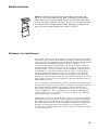
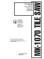
MK-1070 TILE SAW
Model MK 1070
Tile Saw
on
Owner’s Manual
Parts List &
Operating
Instructions
R
For your one (1) year warranty to be
effective, complete the warranty card
(include the serial number) and mail it in as
soon as possible.
Manual Part No. 156172
Revision 8/98
))
((
CAUTION:
Read Safety
And General
Instructions
Carefully
Before Using
Saw For The
First Time.
Table of Contents
General Safety Instructions
Safety Messages and Symbols
Hazard Symbols
Damage Prevention Messages
Safety Label Locations
Saw Features
Motor
Cutting Head
Conveyor Table
Frame and Tower
Water System
Unpacking and Preparation
Initial Assembly
The Cutting Head
Installing the Blade
Blade Tracking
Installing the Water Pump
Electrical Requirements
Sawing Operations
General Cutting Guidelines
Rip Cutting
45° Miter Cutting
Conveyor Table Markings
Maintenance
Removing the Pan
Brush Removal and Replacement
Troubleshooting
Parts Listing
Exploded View
Optional Accessories
Warranty Information
MK Diamond Authorized Service Centers
How to order Repair Parts
Returned Merchandise Policy
pg 2-4
pg 5
pg 6
pg 7-10
pg 11-12
pg 13-14
pg 14
pg 15-18
pg 19
pg 19-20
back cover
back cover
back cover
on
GENERAL SAFETY INSTRUCTIONS FOR THE MK-1070 TILE SAW
For your safety!
These safety precautions should be followed at all times. Failure to follow
these safety precautions could result in injury to yourself and others.
Safety is a combination of operator common sense and alertness at all
times when the saw is being used.
on
For your own safety and protection, do not attempt to operate saw until
it is completely assembled and installed according to the instructions, and
until you read and understand all safety and operating instructions.
))
• Take time to read and understand fully the owner’s manual instructions
and all safety labels attached to the saw.
((
on
• Use safety goggles and ear protectors that comply with ANSI Z87.1.
Wear a dust mask and protect your hands, face and body with the proper
clothing and safety equipment.
• Keep blade guard in place and in working order at all times.
)
((
) done.
• Be sure you have the right saw and blade for the work to be
Forcing a tool to do a job for which it was not designed invites hazardous
results and failure.
• Keep work area clean and safe to avoid accidents.
))
((
• Maintain a “safe zone” and keep all visitors at a safe distance from the
work area.
• Always make sure switch is “off” before plugging unit into electrical
power.
• Never leave saw running unattended. Turn power off.
on
• Be sure the saw is secure and stable before cutting. Never stand on the
saw or use the saw on an unsupported surface.
• Maintain all tools with care for the safest and best performance.
• Should any part of this saw be missing or damaged, or any component fail
to perform properly, shut off the saw and unplug the power source. Replace
the missing, damaged, and/or failed part before resuming operation.
• Always keep alert. Do not allow familiarity (gained from frequent use) to
cause a careless mistake. Always remember that a careless fraction of a
second is sufficient to inflict severe injury.
• THINK SAFETY The operation of any power tool can result in foreign
objects being thrown )into the eyes causing severe damage. Use safety
goggles to comply with ANSI Z87.1.
)
((
FORESIGHT IS BETTER THAN NO SIGHT
2
(
on
A safety message and symbol informs you about potential hazards that
could hurt you or others. Each safety
)) message is preceded by one of the
three words: Danger, Warning, or Caution.
((
Safety Messages
Danger
((
))
You WILL be KILLED or SERIOUSLY injured
if you don’t follow instructions.
on
Warning
You CAN be KILLED or SERIOUSLY injured if you don’t follow instructions.
Caution
((
You CAN be injured and/or your saw can be damaged if you don’t follow
on
instructions.
))
Additional Information as to the nature of the hazard is provided by
the following hazards symbols which appear throughout the manual in
conjunction with safety message alert symbols.
on
Hazard Symbols
))
((
Electrical Shock!
Exposed, frayed or worn electrical motor and/or water pump wiring can
be sources of electrical shock which could cause severe injury or burns.
((
Accidental Starts!
Before applying electrical power to the saw, ensure that the ON/OFF
switch is in the OFF position. Accidental starts can cause injury.
Rotating or Moving Parts!
Keep hands, feet, hair, and clothing away from all moving parts to prevent
injury. Never operate the motor with covers, shrouds, or guards removed.
))
((
on
))
3
damage
prevention
messages
Other important messages that are designed to help prevent damage to
your MK Diamond 1070 tile saw, other property, or the environment are
preceded by the word “notice.”
notice Your MK-1070 tile Saw or other property could be damaged if
you don’t follow instructions
safety
label
locations
4
Safety labels are located according to the drawing below. The labels
contain important safety information. Please read them carefully. These
labels are considered a permanent part of your saw. If a label comes
off or becomes hard to read, contact MK Diamond or your dealer for
replacement.
Description
Part #
Item
Location
B9
Blade Guard
Hearing Protection
156687
D5
Cutting head, top
Model and serial number label
156173
H6
H7
Motor, front side
General safety precautions
155806
Motor, blade side
GFCI cautions
155678
H8
Motor
Amp. max cautions
154822
R
1070 TILE SAW
10 inch blade capacity, with built-in mitering
on
The lightweight portable MK-1070 is a powerful tile cutting machine that
features an innovative adjustable cutting head that allows the operator
to make precision miter cuts quickly and accurately. The MK-1070 is
uniquely designed with the professional in mind to meet all requirements
for any cutting application.
))
Motor
The MK-1070 features a powerful high torque right angle drive universal
motor with the following specifications:
120 volts/ 50/60 hertz, single phase
2000 watts 17.6 ampere
4300 r.p.m.
The heavy-duty pinion and gear wheel assembly is permanently lubricated
in the sealed right-angle gearbox.
((
Saw Features
Caution
Wear hearing protection when operating saw.
Cutting Head
The cutting head includes a built-in, fully adjustable, 45° miter system.
The 10 inch blade capacity yields a depth of cut of 3-3/4” or 2-1/8” at
a miter. The hinged blade guard allows easy blade changes, and is wide
enough to accept 8” profile wheels.
Conveyor Table
The rugged conveyor table assembly utilizes a linear guide bar and cover
that provides accurate, minimal maintenance operation, and increases
operator control and safety. The full movement of the table allows for the
cutting of 24” tile, or full diagonal cutting 18” tile.
Frame and Tower
The unitized structural steel frame and cast aluminum tower of the MK1070 provide maximum strength and rigidity, while keeping weight to a
minimum. The MK-1070 is very portable at 107 pounds and an overall
size of 41”L x 23”W x 18”H. Carrying handles are provided for ease of
transporting.
Water System
The water system of the MK-1070 consists of a thermoplastic water
reservoir and a submersible recirculating pump that connected to water
tubes in the blade guard in order to provide a continuous supply of water
to both sides of the blade. The water reservoir will not rust or peel, and
can be removed for easy cleaning.
5
Unpacking, and
Preparation
Carefully open carton. Remove the accessory pack. Lift the saw frame
out of the carton by the frame, and place onto a level work surface. The
saw frame may also be placed onto the optional stand (see Stand under
Optional Accessories) at this point.
Open the accessory pack, and check each item with the contents list and
illustration below, making certain that all items are accounted for and in
good condition before discarding any packing material. If there are any
missing or damaged parts, call our toll free number 1-(800) 421-5830
for instructions before proceeding with the assembly.
Contents of carton: Saw frame and Accessory Pack
cutting head
saw frame
Accessory pack contains:
water pump hose adapter
cabezal de corte
escudo contra
salpicaduras
adaptador para la
bomba de aguar
guía de corte
manual para la bomba
®
Dia
mo
1-8 nd
00 Pro
-42 du
1-5 cts,
83 Inc.
0
manguera de la bomba de
agua con abrazadera
bomba de agua
llave para la tuerca
del disco
llave para el eje del disco
perno de mariposa
disco de 7” (18 cm) para
baldosas y azulejos
tarjeta de garantía
manual del propietario
splash guard
drain plug
water pump hose with clamp
rip guide
wing screw
height adjustment knob
water pump
3/8” washer
blade shaft wrench
blade nut wrench
cutting kit
®
6
10” tile blade
pump manual
Di
am
o
1 nd
-80 P
0-4 rod
owner’s manual
21 uct
s
-58
,
30 Inc.
warranty card
Initial Assembly
Warning
For your own safety and protection, do not attempt to operate this saw
until it is completely assembled according to the instructions, and until you
understand the machines capabilities and the potential hazards associated
with it.
The Cutting
Head
The Cutting Head Assembly has been professionally installed and aligned
to insure accurate cutting in both the 90° and 45° plane. Adjustments to
the Cutting Head should only involve its designed feature for miter cutting.
Great focus and precision went into the alignment process, therefore
it is advisable not to break or alter any of the factory adjustments. If
transportation or maintenance necessitates some disassembly, the Cutting
Head may be removed by unthreading the circular height adjustment knob,
and sliding the entire assembly from the rear post pin.
Loosen the davies knob and the wing nut on the blade guard, raise the
blade guard to it’s highest position, and retighten the wing nut. Remove
the blade shaft nut and outer flange using the wrenches provided. Place
the blade onto the shaft making sure that the rotation arrow on the blade
faces counter-clockwise (triangular shaped black knob), when viewed from
the blade side of the saw. Reinstall the outer flange and blade shaft nut,
tightening the nut with the wrenches provided. Be careful not to overtighten! Lower the blade guard and retighten the davies knob and wing nut.
installing the
blade
Blade Tracking
1/4"
Loosen the adjustment knob and lower the cutting head until the blade
is 1/4” below the surface of the conveyor table. Tighten the height
adjustment knob to hold the cutting head in this position. Ensure that the
blade tracks near the center of the channel in the conveyor table, and
that the table moves freely from front to back (refer to Securing the Table
if table does not move freely). If the blade does not track near the center
of the channel or the conveyor table does not move freely at this point,
stop and call MK Diamond Customer Service at 1-(800) 421-5830.
The Cutting Head Assembly has been factory adjusted to insure proper
cutting. The blade should track near the center of the 90° channel in the
conveyor table, and should move freely from front to back. If the blade
strikes the side of the channel, does not track smoothly, or appears too
far left or right of center, call MK Diamond Customer Service before
proceeding.
7
)) onto the water pump. Slide one end
Screw the water pump hose adapter
of the water hose onto the adapter and place the pump in the water pan
cradle. Slide the other end of the water hose onto the fitting at the back
of the blade guard. Plug the water pump into the three-prong receptacle
on the motor. Fill the pan with clean water, insuring that the water level
is above the pump intake to insure proper operation. The water pump is
completely submersible, has sealed bearings and is thermally protected.
Cold weather and low voltage may cause the pump not to function
properly. Be sure that the pump is clear of sediment before operation.
See the pump manual separately enclosed for all pump information.
((
installing the
water pump
Warning
This pump is supplied with a grounding conductor and a grounding type
attachment plug. To reduce the risk of electrical shock, connect only to a
properly grounded, ground-type receptacle.
•Do not use this pump in flammable liquid.
on
•Do not remove
grounding pin from electrical cord.
•Do not connect to any voltage other than that shown the pump.
Notice: Do not run the pump dry. Also be sure to disconnect and remove
the water pump when cutting dry.
))
The MK-1070 tile saw is wired for 120V, single phase operation, and
draws 17.6 amps at 120V. This is a large load and if the machine is
operated on any circuit that is already close to it’s capacity, the circuit
breaker may be tripped. If this occurs, eliminate other loads from the
circuit. A separate circuit protected by a 20 amp breaker is ideal. If other
loads do not exist and power failure still occurs, have the circuit inspected
by a qualified electrician.
((
electrical
requirements
Warning
This equipment must be grounded.
The MK-1070 is equipped with a grounded power cord and plug. To
reduce the risk of electrical shock, connect only to a properly grounded,
ground- type receptacle. If used, extension cords must be three conductor
type with three prong ground type plugs and receptacles. Use only UL
listed cords and connect the saw as close to the power source as possible.
Always repair or replace extension cords if they become damaged. Use the
following chart for cord selection.
Length of extension Cord
Minimum Wire Gauge
up to 50’
#14
up to 75’
#12
over 75’
#10
Notice: Use of undersize extension cords results in low voltage to the
motor, which can result in burnout and premature failure. MK warns that
equipment returned to us, showing signs of being run in a low voltage
condition through the use of undersized extension cords, with be repaired
or replaced totally at the customer’s expense, regardless of current
warranty condition.
8
((
In the event of a malfunction or breakdown, grounding provides a path of
least resistance for electric current to reduce the risk of electric shock.
This tool is equipped with an electric cord having an equipment-grounding
conductor and a grounding plug. The plug must be plugged into a
matching outlet that is properly installed and grounded in accordance with
all local codes and ordinances.
•Do not modify the plug provided - if it will not fit the outlet, have the proper
outlet installed by a qualified electrician.
•Improper connection of the equipment - grounding conductor can result
in a risk
on of electric shock. The conductor with the insulation having
an outer surface that is green, with or without yellow stripes, is the
equipment grounding conductor. If repair or replacement of the electric
cord or plug is necessary, do not connect the equipment - grounding
conductor to a live terminal.
•Check with a qualified electrician or service personnel if the grounding
instructions are not completely understood, or if in doubt as to whether
the tool is properly grounded.
•Use only 3-wire extension cords that have 3- prong grounding plugs and
3-pole receptacles that accept the tool’s plug.
•Repair or replace damaged
)) or worn cord immediately. See Table 1 for
proper extension cord gage requirements.
Warning
This tool is intended for use on a circuit that has an outlet that looks like
the one illustrated in Sketch A in Figure 1. The tool has a grounding plug
that looks like the plug illustrated in Sketch A in Figure 1. A temporary
adapter, which looks like the adapter illustrated in Sketches B and C, may
be used to connect this plug to a 2-pole receptacle as shown in Sketch
B if a properly grounded outlet is not available. The temporary adapter
should be used only if a properly grounded outlet is not available. The
temporary adapter should be used only until a properly grounded outlet
can be installed by a qualified electrician. The green-colored rigid ear,
lug, and the like, extending from the adapter must be connected to a
permanent ground such as a properly grounded outlet box.
Note
Use of a temporary adapter is not permitted in Canada.
Additionally, the water pump requires the use of a Ground Fault Circuit
Interrupter. Therefore, when using the water pump, plugged into the
motor receptacle, this tool must be plugged into a properly installed and
grounded Ground Fault Circuit Interrupter outlet, like the one illustrated
in Sketch D in Figure 1. If a Ground Fault Circuit Interrupter outlet is
not available, MK Diamond has available, as an accessory item, a plug
- in Ground Fault Circuit Interrupter that may be plugged into a properly
installed and grounded 3-pole outlet. See Sketch E in Figure 1.
9
Figure 1
Grounding methods
on
metal screw
cover of grounded
outlet box
Position of Tile Saw
(B)
adapter
tool
))
(C)
drip loop
(A)
supporting
surface
on
grounding
means
((
power
supply cord
grounding pin
(D)
(E)
on
To avoid the possibility of the appliance plug or receptacle getting wet, position tile saw to one side of a
wall mounted receptacle to prevent water from dripping onto the receptacle or plug. A “drip loop,” shown
in the figure below, should be arranged by the user for the cord, connecting the saw to a receptacle.
The “drip loop” is that part of the cord below the level of the receptacle, or the connector if an extension cord
is used, to prevent water traveling along the cord and coming in contact with the receptacle.
Warning
((
If the plug or receptacle does get wet, don’t unplug the cord. Disconnect the fuse or circuit breaker
that supplies power to the tool. Then unplug and examine for presence of water in the receptacle.
))
Extension Cords
((
))
Use only extension cords that are intended for outdoor use. These extension cords are identified by a
marking “Acceptable for use with outdoor appliances; store indoors while not in use.” Use only extension
cords having an electrical rating not less than the rating of the product. Do not use damaged extension
cords. Examine extension cord before using and replace if damaged. Do not abuse extension cord and
do not yank on any cord to disconnect. Keep cord away from heat and sharp edges. Always disconnect the
extension cord from the receptacle before disconnecting the product from the extension cord.
Warning
To reduce the risk of electrocution, keep all connections dry and off the ground. Do not touch plug with
wet hands.
Ground Fault Circuit Interrupter (GFCI) protection should be provided on the circuit(s) or outlet(s) to
be used for the tile saw. Receptacles are available having built-in GFCI protection and may be used for
this measure of safety.
Caution
Table 1
Minimum gage for cord
Volts Total length of cord in feet
120 V —
25 ft.
50 ft. 100 ft.
150 ft.
240 V —
50 ft.
100 ft. 200 ft.
300 ft.
Ampere Rating
more than not more than AWG
0
6
18
16 16
14
6
10
18
16 14
12
10
12
16
16 14
12
12
16
14
12not recommended
10
Notice: Use of undersize extension cords results in low voltage to the motor, which can result in burnout
and premature failure. MK warns that equipment returned to us, showing signs of being run in a low
voltage condition through the use of undersized extension cords, will be repaired or replaced totally at the
customer’s expense, regardless of current warranty condition.
on
general cutting
guidelines
• Match blade specification with the material being cut, following the
manufacturer’s recommendation.
)) saw, inspect the arbor shaft, flanges
• Before mounting the blade on the
and the blade for damage and uneven wear
• Inspect the diamond blade for damage periodically during use for fatigue
cracks and segment damage.
• Be sure that the arbor hole diameter of the blade matches the blade
shaft diameter.
• Be sure that the direction of rotation arrow on the blade is oriented
properly, and that the blade shaft nut is securely tightened with the
wrenches provided.
• Check for continuous flow of water to both sides of the blade before
cutting.
((
Sawing Operations
))
((
Warning
• Never operate any saw without safety guards in place.
• Do not force the blade into the the material: allow the blade to cut all
it’s own speed.
• Do not cut dry with blades designed for wet cutting.
• Do not make long continuous cuts with dry cutting blades: allow the
on by turning in the air every few minutes.
blade to cool
• Do not exceed the blades safe operating speed.
• Do not operate the saw with a blade diameter larger than the saws
capacity.
• Do not cut or grind with the side of the blade, or cut a curve or a radius.
For Best Results...........Use MK Diamond Blades.
))
Rip cutting is the term used to describe
cutting the material flat on the
conveyor table, either on the square or the diagonal. When cutting the
material on the square, position the rip guide to the desired cutting
dimension, and tighten the thumb screw to secure it in place. Firmly hold
the material against the conveyor table back stop and the rip guide while
cutting. When cutting diagonally, position the material using the conveyor
table back stop and the optional dual 45° flat angle guide. For cutting
materials at other angles, use the 0-90° protractor to align the material
to the desired angle.
--------------
((
rip cutting
----------------
square cut
diagonal cut
Warning
Do not attempt to cut pieces too small to hold by hand outside the blade
guard. Avoid awkward hand positions where a sudden slip could cause a
hand to move into the blade.
When cutting a large piece of material, make sure it is fully supported.
Hold workpiece firmly against conveyor table, back stop and guide. Only
feed the material fast enough for the blade to cut. DO NOT FORCE.
11
((
45° Miter Cutting
To use the built-in 45° miter feature, raise the cutting head to it’s highest
position. Loosen the miter adjustment knob, rotate the motor mount until
it rests on the 45° position stop screw, and then retighten the adjustment
knob. Lower the cutting head until it rests on the adjustment screw at
the bottom of the radial slot on the tower. Be sure to retighten the height
adjustment knob. Insure that conveyor cart moves freely from front to back.
Warning
Do not attempt to adjust the stop screw located on the tower, as this
will affect the factory setting of the built-in 45° feature. The cutting head
adjustment knob must rest against this stop, or the blade will bind during
cutting, possibly resulting in injury to the operator or damage to the saw.
on
conveyor table markings
The markings on the conveyor table back stop are used to aid in
cutting tile to particular dimensions. The scale on the top of the back
stop is used for setting the rip guide indicator to the desired cutting
dimension. The scale is used to indicate the approximate position of
the material being cut.
((
))
securing the conveyor
table
The conveyor table may be secured into position for transportation
and storage. Rotate the guide bar cover in a clockwise direction until
the conveyor table is tight. To unsecure, rotate the guide bar cover
counter-clockwise until the table moves freely.
Caution
This is not a locking device. The conveyor table may still move during
transport if moved quickly.
12
))
Maintenance
((
Periodic maintenance of the MK-1070 will insure long life and trouble-free
operation. The required maintenance consists of the following:
Clean the saw after every use. Clean out the pan with soap and water
(see removing the pan). Raise the conveyor table to clean the linear
bearing and the guide bar. Lubricate the guide bar periodically with a light
machine oil. Wipe off the cutting head and other surfaces.
on
WARNING
((
on
For your safety, turn off the switch and unplug the saw from the power
source before maintaining or cleaning the saw. If the power cord becomes
damaged in any way, replace it immediately. When cleaning the saw,
DO NOT get the motor wet. Electrical shock could occur. Excessive
moisture can cause damage to the internal parts. DO NOT Service the
motor’s internal parts yourself. Call MK Diamond’s customer service
department at 1-800-421-5830 for help in solving any problems.
))
Unplug the MK-1070 from the power source. Unplug and remove the
water pump from the pan. Drain the water from the pan by removing the
drain plug. Slide the pan straight out through the front of the saw frame.
When reinstalling the pan, make sure that the lip of the pan is aligned
with the notches in the frame brackets and that the bottom of the pan
rests securely on the frame cross bars.
WARNING
))
Turn off the switch and unplug the saw from the power source before
removing the pan.
((
removing the pan
13
After extended use the need may arise for the brushes to be replaced
(when approximately 1/4” of the brush remains). First, using a flat
bladed screwdriver, remove the brush cup from the motor cover, by
unscrewing the cap screws. Remove the old brush from it’s holder
and replace with the new brush. Remove and replace the other brush.
Reinstall the brush caps and tighten the cap screws.
))
((
brush removal and
replacement
on
WARNING
((
Turn off the switch and unplug the motor from the power source
))
before inspecting or replacing brushes.
NOTICE: Use only MK DIAMOND authorized brushes to insure
compatibility and avoid motor damage.
Trouble Shooting
WARNING
For your safety, turn off the switch and unplug the saw from the power
source before performing any troubleshooting adjustment.
14
if motor won’t
stay on
Check Ground Fault Interruption Switch. Check for correct extension
cord size. Check voltage and circuit breaker from power source. Use
20 amp power. Check the integrity of the brushes.
if blade won’t
cut
Check for worn out diamond edge. Check that blade is rotating in the
same direction as the rotation arrows. Check that the blade is the
correct specification for the material being cut.
if conveyor
table won’t
move smoothly
Check that the guide bar cover is not secured. Check that the guide
bar is clean and free of dirt. Lubricate guide bar periodically with light
machine oil per maintenance instructions.
if water won’t
flow evenly to
both sides of
the blade
Check that the water line is clear of dirt. Check that the water jets in
the blade guard are clear. Check that the pump filter is not clogged.
Parts Listing- MK-1070 Tile Saw
MK-1070 Parts List
Models
Part #Description
155882
MK-1070 Tile Saw 120V/17.6A
155885
MK-1070 Tile Saw 240V/7.5A
156182
MK-1070 Tile Saw 240V/7.5A, Australia
ItemDescription
A
Assembly, Accessory Pack
A1 Carton, Accessory Pack
A2 Foam, Accessory Pack Carton
A3Owner’s Manual, 1070
A4 Card, MK Warranty Registration
A5 Blade, MK-415 Continuous Rim Wet Tile,
10 Dia. X 5/8 arbor X .080 X 10mm segment
A6 Wrench, Blade Nut, 15/16 Closed End
A7 Casting, Rip Guide
A8 Casting, Large Rip Guide
A9 Casting, Dual 45° Flat Angle Guide
A10 Protractor
A12 Stick, Dressing, 60 Grit, 8 X 2 X 1
Qty
n/a
1
1
1
1
Part #
n/a
156178
156179
156172
155037
1
1
1
1
1
1
1
155619
134684
134551
154014
134577
134569
152792
B
Assembly, Blade Guard
B1 Casting, Blade Guard
B2 Tube, 2.5” Water
B3 Screw, 5/16-18 X 1/4 Socket Head Set
B4 Fitting, Brass, 1/8 MNPT X 1/4 BARB
B5 Stud, 5/16-18 X 1 1/2, Full Thread
B6 Knob, Davies
B7 Wingnut, 5/16-18 Nylock
B8 Washer, 5/16 SAE Flat
B9 Label, Caution, Hearing Protection
n/a
1
2
2
1
1
1
1
2
1
n/a
155699
155512
152607
155809
153680
151681
151746
151754
156687
C
Assembly, Carton
C1 Carton
C2 Pallet
n/a
1
1
n/a
156268
153901
D
Assembly, Cutting Head
D1 Head, Cutting
D2 Knob, 3/8-16 X 1 Adjustment
D3 Washer, 3/8 SAE Flat
D4 Knob, 3/8-16 X 1 Three Prong
D5 Tag, Serial Number
D6 Tack, Metal. 1/4 Head
D7 Screw, 10-32 X 1 Hex Head Cap
D8Nut, 10-32 Hex
n/a
1
1
1
1
1
2
2
2
n/a
155692
137786
150923
156175
156173
155659
156270
156269
E
Assembly, Frame
E1 Pan, Water
E2 Plug, Rubber Drain
E3 Frame, 21 X 41
E4 Plate, Adjustment
E5 Pin, 3/16 X 3/8 Roll
n/a
1
1
1
2
2
n/a
153262
153439
153209
151758
151783
F
Assembly, Guide Bar
F1 Bar, 3/4 X 37 Guide
F2 Cover, Guide Bar
F3 Spacer, Guide Bar Cover
F4 Screw, 5/16-18 X 1 Hex Head Cap
F5 Washer, 5/16 Split Lock
n/a
1
1
2
2
2
n/a
153492
153219
152393
151743
151747
15
16
F6 Washer, 5/16 SAE Flat
2
151754
G
Assembly, Linear Bearing
G1 Casting, Linear Bearing
A) Bearing, Multilube
G2 Screw, 5/16-18 X 1 Hex Head Cap
G3 Washer, 5/16 Split Lock
n/a
1
2
152227
2
2
n/a
G4 Washer, 5/16 SAE Flat
G5 Shim, .004 X 5/16 ID X 1/2 OD
2
~4
151754
152519
H
Assembly, Motor, 120V
H1 Motor, 120V/15A
H2 Screw, 10-32 X 3/4 Flat Head Phillips Cap
H3 Screw, 14mm X 30mm Flat Head Socket Cap
H4 Flange, 2-3/8 Blade
H5Nut, Blade Shaft, 5/8-16 UNF Hex
H6 Label, Warning, Read Owner’s Manual
H7 Label, Caution, GFCI, 1 X 2 1/8
H8 Label, Caution, 1 Amp Max., 1 X 2 1/8
HA
Assembly, Motor, 240V
HA1 Motor, 240V/7.5A
HA2 Screw, 1/4-20 X 3/4 Flat Head Phillips Cap
HA3 Screw, 14mm X 30mm Flat Head Socket Cap
HA4 Flange, 2-3/8 Blade
HA5Nut, Blade Shaft, 5/8-16 UNF Hex
HA6 Label, Warning, Read Owner’s Manual
HA7 Label, Caution, GFCI, 1 X 2 1/8
HA8 Plug, NEMA6-15P 220V/15A
HB
Assembly, Motor, 240V, Australia
HB1 Motor, 240V/7.5A
HB2 Screw, 1/4-20 X 3/4 Flat Head Phillips Cap
HB3 Screw, 14mm X 30mm Flat Head Socket Cap
HB4 Flange, 2-3/8 Blade
HB5Nut, Blade Shaft, 5/8-16 UNF Hex
HB6 Label, Warning, Read Owner’s Manual
HB7 Label, Caution, GFCI, 1 X 2 1/8
HB8 Plug, 240V/10A Australia
n/a
1
2
2
2
1
1
1
1
n/a
1
2
2
2
1
1
1
1
n/a
1
2
2
2
1
1
1
1
n/a
155533
153902
156174
135830
135848
155806
155678
154822
n/a
156180
154657
156174
135830
135848
155806
155678
155391
n/a
156180
154657
156174
135830
135848
155806
155678
156267
J
Assembly, Motor Mount
J1 Mount, Motor
J2 Screw, 1/2 X 3/4 Socket Head Shoulder,
w/ 3/8-16 X 5/8 thread
J3 Screw, 1/2 X 1-1/4 Socket Head Shoulder,
w/ 3/8-16 X 5/8 thread
J4 Spring, Miter
J5Deflector, Air
J6 Screw, 10-24 X 1/2 Pan Head Phillips Cap
n/a
1
n/a
155694
1
156177
1
1
1
2
156176
155696
155695
151744
K
Assembly, Post
K1 Casting, Post K2 Plate, Pressure
K3 Screw, 3/8-16 X 2 1/2 Hex Head Cap
K4 Washer, 3/8 Split Lock
K5 Shaft, 10.63” Pivot
K6 Screw, 3/8-16 X 1/2 Socket Head Set
K7 Stop, Cutting Head
K8 Screw, 10-32 X 1 Pan Head Slotted Cap
K9Nut, 10-32 Hex
K10 Screw, 1/4-20 X 1 1/4 Hex Head Cap
K11 Washer, 1/4 Split Lock
n/a
1
1
2
2
1
1
1
1
1
1
1
n/a
155670
155671
227178
150925
153254
153710
156256
156270
156269
152122
152591
135855
151743
151747
M
Assembly, Roller Wheel
M1 Bracket, Roller Wheel
1
1
151756
154021
M2 Wheel, Roller
M3 Screw, 1/4-20 X 1 1/2 Hex Head Cap
M4 Washer, 1/4 SAE Flat
M5Nut, 1/4-20 Hex
M6 Screw, 5/16-18 X 1 Hex Head Cap
M7 Washer, 5/16 Split Lock
M8 Washer, 5/16 SAE Flat
1
1
1
1
2
2
2
151799
151914
151915
151893
151743
151747
151754
N
Assembly, Splash Curtain
N1 Curtain, Splash
N2 Bracket, Splash Curtain “L”
N3 Wingscrew, 1/4-20 X 1/2
N4 Washer, 1/4 SAE Flat
n/a
1
1
1
1
n/a
134841
155901
151888
151915
P
n/a
n/a
P1 Table
P2 Table, Large Extension
P3 Screw, 1/4-20 X 1/2 Socket Head Set
Assembly, Table
1
1
2
154440
154499
155804
Q
Assembly, Water Pump, 120V
MK
Q1 Pump, Water, 120V
Q2 Fitting, Plastic, 1/4 FNPT X 1/4 BARB
Q3 Hose, Vinyl, 1/4 ID
Q4 Clamp, Flow, 1/4-1/2
Q5Owner’s Manual, Water Pump
Q6 Carton, Water Pump
Q7 Insert, Foam, Water Pump
QA
Assembly, 240V Water Pump
MK
QA1 Pump, 240v Water
QA2 Elbow, Plastic, 90∞, 1/4 MNPT X 1/4 FNPT
QA3 Fitting, Plastic, 1/4 FNPT X 1/4 BARB
QA4 Hose, Vinyl, 1/4 ID
QA5 Clamp, Flow, 1/4-1/2
QA6 Plug, Nema 5-15P 15A/120V
1
151271-
1
1
2’
1
1
1
1
1
151271
128397
132951
154394
155745
154016
154017
151714-
1
1
1
2’
1
1
151714
151018
128397
132951
154394
150869
17
MK-1070 Exploded View
Optional Accessories
MK
Stand- the sturdy and strong, tubular steel folding stand raises the
MK-1070 to a comfortable working height, and allows easy portability.
When setting the saw on the stand, be sure that the saw frame seats
firmly in the stand brackets. The “point” of the V-strut of the saw frame
fits over the small V-shaped stand bracket, and the strut opposite the
point fits over the large stand bracket. (part # 153331)
MK Diamond 1 Year Limited Warranty
MK Diamond under this warranty is expressly limited to the repair or replacement,
at its option, that are proven to be defective in materials or workmanship under
normal use during the applicable warranty time period. All repair and replacement
will be performed at MK Diamond Products, Torrance, California, or at a
service facility designated by MK Diamond. The warranty of defective materials
or workmanship is limited to such part or parts as inspection shall disclose to
have been defective. This warranty does not apply to defects caused by damage,
unreasonable use, faulty repairs made by others or defects caused by failure
to provide reasonable maintenance, while in the possession of the consumer.
Anything replaced under the warranty becomes the property of MK Diamond
Products, Inc. All parts replaced under warranty will be considered as part of the
original product and any warranty on these parts will expire coincidently with the
original product warranty.
Parts, installed by an authorized repair center will be repaired or replaced under
warranty without charge for parts or labor. If installed by anyone else, replacement
parts will be repaired or replaced under warranty without charge for parts,
but any labor charges will be the responsibility of the purchaser. This warranty
is void if the product, or any of its components, are altered or modified by the
consumer purchaser, or if the product is used in a manner or with a blade not
recommended by the manufacturer.
MK Diamond disclaims any responsibility for loss of time or use of the equipment,
transportation, commercial loss or any other incident or consequential damage.
Any implied warranties are limited to the duration of this written limited warranty.
Some states do not allow the exclusion or limitation of incidental or consequential
damages, so the above exclusions and limitations may not apply to you. This
warranty gives you specific legal rights, and you may also have other rights which
vary from state to state.
19
Exclusions
MK does not warrant the following components, which carry their own manufacturer’s warranty for the indicated periods:
• Gasoline Engines (Manufacturer’s Warranty Period)
Description
Kohler
Wisconsin Robin
Honda
Briggs & Stratton
Length of Warranty
2
2
2
2
years
years
years
years
• Transmissions (Manufacturer’s Warranty Period)
Description
Eaton
Length of Warranty
3 years
• Electric Motors (Manufacturer’s Warranty Period)
Description
Length of Warranty
Baldor
Leeson
Milwaukee
Black & Decker
FLEX/Intercraft
RAE
1 year
1 year
Lifetime
1 year
1 year
1 year
The foregoing express warranties are in lieu of all other warranties. MK disclaims all other warranties, including, without
Diamond Blade and Core Bit Warranty
• Laser Welded Blade and Bit Warranty
If the laser weld between the segment and the steel core or barrel fails during the normal use, the blade or bit will be replaced
free of charge.
• Brazed Blade and Bit Warranty
If the brazed bond between the segment and the core or barrel fails within the first .050 of segment wear, the blade or bit
will be replaced free of charge.
• Continuous Rim Blade Warranty
If the bond between the rim and the core fails during normal use of the blade, the blade will be replaced free of charge.
These implied warranties do not cover abuse to, or misapplication of the blade or bit. MK Diamond under this warranty is
expressly limited to the replacement or repair at MK Diamond’s Torrance manufacturing facility.
20
Model MK 1070
Owner’s Manual
Parts List &
Operating
Instructions
HOW TO ORDER REPAIR PARTS
please have the following
information ready before calling:
SERIAL NUMBER OF YOUR SAW
MODEL NUMBER OF SAW WHERE PURCHASED AND WHEN PART NUMBER
PART DESCRIPTION
all parts listed may be ordered from
your local distributor or from mk diamond. If the part
is not stocked locally, call our toll free number listed
below and ask for our customer service department.
For
technical support call: 1 (800) 474-5594 or
1 (310) 257-2845.
RETURNED MERCHANDISE POLICY
Should you need to return any product you have
purchased from MK Diamond, please observe the
following:
Our customer service department should
be
contacted for approval to return
merchandise.
Merchandise will not be accepted without a
RETURNED GOODS authorization number. All
returned merchandise must be shipped prepaid to
destination. All returned merchandise must have
been purchased within the previous 12 months. A
restocking charge of 15% may be billed.
MK Diamond Products, Inc.
1315 Storm Parkway. Torrance, CA 90509-2803
1 (800) 421-5830
FAX 1 (310) 539-5158
R