1
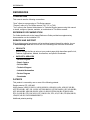
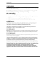
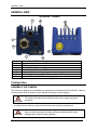
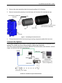
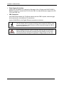
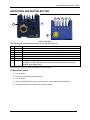
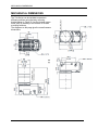
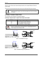
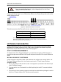
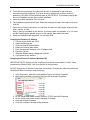
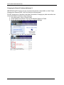
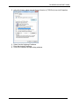
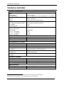
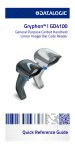
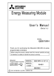
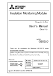
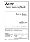
T4x-Series QuickStart Guide Publication # 821002560 Datalogic Automation, Inc. 6301 West Old Shakopee Rd Suite A Bloomington MN 55438 USA T4x-Series™ Reference Manual Edited: 07/2013 © 2013 Datalogic Automation, Inc. ALL RIGHTS RESERVED. Protected to the fullest extent under U.S. and international laws. Copying or altering of this document is prohibited without express written consent from Datalogic Automation, Inc. (DLA) Datalogic and the Datalogic logo are registered trademarks of Datalogic S.p.A. in many countries, including the U.S.A. and the E.U. T4x-Series, Vision Program Manager, Control Panel Manager, and Impact are trademarks of Datalogic Automation S.r.l. All other brand and product names mentioned herein are for identification purposes only and may be trademarks or registered trademarks of their respective owners. DLA makes no representations or warranties for merchantability or fitness for any particular purpose, regarding DLA’s software or hardware. DLA shall not be liable for errors contained herein or for incidental or consequential damages in connection with the furnishing, performance, or use of this publication or its contents. DLA reserves the right to revise this publication from time to time and to make changes in the content hereof without obligation to notify any person of such revision or changes. Printed 9 July 2013 ii REFERENCES REFERENCES CONVENTIONS This manual uses the following conventions: "User" refers to anyone using an T4x-Series camera. "Camera" refers to a T4x-Series camera (T40, T47, or T49). "You" refers to the System Administrator or Technical Support person using this manual to install, configure, operate, maintain, or troubleshoot a T4x-Series camera. REFERENCE DOCUMENTATION For further details refer to the Impact Reference Guide provided as supplementary documentation on the installation CD. SERVICE AND SUPPORT DLA provides several services as well as technical support through its website. Log on to www.datalogic.com and click on one of the following links for further information: • PRODUCTS Search through the links to arrive at your product page which describes specific Info, Features, Applications, Models, Accessories, and specific Downloads. • SUPPORT & SERVICES - Service Program - Repair Centers - On-Line RMA - Technical Support - Industrial Automation - Partner Program - Downloads PATENTS This product is covered by one or more of the following patents: Design patents: EP 1,950,486. Utility patents: US6,512,218 B1; US6,616,039 B1; US6,808,114 B1; US6,997,385 B2; US7,053,954 B1; US7,102,116 B2; US7,282,688 B2; US7,387,246 B2; US7,433,590 B2; US7,468,499 B2; US8,058,600 B2; US8,113,430 B2; EP996,284 B1; EP999,514 B1; EP1,014,292 B1; EP1,128,315 B1; EP1,396,811 B1; EP1,413,971 B1; EP1,804,089 B1; JP4,435,343 B2; CN ZL200680050007,8. Additional patents pending. iii COMPLIANCE COMPLIANCE For installation, use, and maintenance, it is not necessary to open the camera. Opening the camera will void the warranty. Connect Ethernet and dataport connections to a network which has routing only within the plant or building and no routing outside the plant or building. EMC COMPLIANCE In order to meet the EMC requirements: • connect the camera chassis to the plant earth ground by means of a flat copper braid shorter than 100 mm; • for CBX connections, connect the pin "Earth" to a good Earth Ground; • for direct connections, connect the main interface cable shield to pin K of the 19-pin connector. POWER SUPPLY ATTENTION: READ THIS INFORMATION BEFORE INSTALLING THE PRODUCT This product is intended to be installed by Qualified Personnel only. This product is intended to be connected to a UL Listed Direct Plug-in Power Unit marked LPS or “Class 2”, rated 10-30Vdc 1-0.33A. CE COMPLIANCE Warning: This is a Class A product. In a domestic environment this product may cause radio interference in which case the user may be required to take adequate measures. FCC COMPLIANCE Modifications or changes to this equipment without the expressed written approval of DLA could void the authority to use the equipment. This device complies with PART 15 of the FCC Rules. Operation is subject to the following two conditions: (1) This device may not cause harmful interference, and (2) this device must accept any interference received, including interference which may cause undesired operation. This equipment has been tested and found to comply with the limits for a Class A digital device, pursuant to part 15 of the FCC Rules. These limits are designed to provide reasonable protection against harmful interference when the equipment is operated in a commercial environment. This equipment generates, uses, and can radiate radio frequency energy and, if not installed and used in accordance with the instruction manual, may cause harmful interference to radio communications. Operation of this equipment in a residential area is likely to cause harmful interference in which case the user will be required to correct the interference at the user’s own expense. iv GENERAL VIEW GENERAL VIEW T4x-Series™ Camera 6 5 7 1 2 8 3 1 2 3 4 5 6 7 8 4 Power Indicator LED Power, Serial Interface, and I/O Connector MAC Address label Ethernet Connector Ethernet Network Presence LED Not Used – No Connection Indicator Lights (see page Error! Bookmark not defined.) Reset and Camera Button Event (see page 8) Configuration ASSEMBLE THE CAMERA The first step to perform is to assemble any accessories that make up the T4x-Series™ camera. A lens must be used. A strobe or other external illuminator may be required. CAUTION The camera must be disconnected from the power supply during this procedure. 1. In a dust-free environment, remove the Camera Lens Cover by unscrewing it. CAUTION Do not touch the sensor aperture, lens glass or lens cover glass. These areas must be kept clean. Avoid any abrasive substances that might damage these surfaces during cleaning. 5 T4x-SERIES QUICKSTART GUIDE 2. Remove the sensor protection label (dust cap) by pulling it off of the base. 3. Mount a lens by slowly screwing it onto the base until it arrives at the mechanical stop. Anti-vibration components (optional) Protective Film on front of cover (remove before calibration) Lens Cover Lens Camera Figure 1 – Assembling the Camera and Lens 4. To keep dust and dirt off of the lens during mounting, temporarily replace the lens cover. Connect the System In the typical standalone layout shown in the figure below, an EtherNet host is connected to the camera. The camera can use an external trigger to signal image acquisition. The CBX is used to facilitate the connection between the camera and the host interface, external trigger, and optional input and output devices. Camera PG-120 CAB-PG-0002 + BA400 CAB-GE0x CBX500 Ethernet Host (Data collection + T4xSeries configuration) CAB-SCSxx Ext. Trigger I/O T4x-Series™ Standalone Layout to Ethernet Host 6 CONNECT THE SYSTEM • Power Supply Connection Use the PG-120 power Kit (3 versions for European, UK or US plug) and CAB-PG-0002 + BA400 connector to connect the PG-120 to the CBX. An alternative power supply to the PG120 is the PWR-120. • CBX Connection Use CAB-SCSxx between the T4x-Series camera and the CBX for power, external trigger device (photocell), and additional I/O connections. Use the CAB-GE0x for the Gigabit Ethernet connection to the host. NOTE The T4x-Series does not support sourcing power towards the CBX in order to power I/O devices. These devices must be powered through the CBX or from an external source. CAUTION Do not connect GND and SGND to different (external) ground references. GND and SGND are internally connected through filtering circuitry which can be permanently damaged if subjected to voltage drops over 0.8 Vdc. 7 T4x-SERIES QUICKSTART GUIDE INDICATORS AND KEYPAD BUTTON 3 4 5 6 7 2 1 8 Figure 2 - Indicators The following LED indicators are located on the camera (Figure 2): 1 2 3 4 5 6 7 8 POWER NET ONLINE OUT1 OUT2 OUT3 BUSY BUTTON On – camera is connected to power On – Ethernet link is established. Blinking - data transmission On – Loaded tasks will be executed based on their trigger parameters On – Output 1 is on On – Output 2 is on On – Output 3 is on LED blinks during image and flash memory access Camera Reset: See Note below To trigger the Camera Button event, press and release the button (Internal software event trigger only) Note: Camera Reset will restore the factory camera settings. This includes deleting all user settings on the camera and resetting the camera’s IP Address and Mask to the factory default. To Reset the Camera 1. Turn off power. 2. Press and hold the Camera Reset button. 3. Turn on power. 4. When all the LED indicators turn on and remain lit, release the Camera Reset button. 5. Wait approximately 30 seconds for the camera to restart. 8 MECHANICAL DIMENSIONS MECHANICAL DIMENSIONS The T4x-Series can be installed to operate in different positions using the body mounting bracket shown in Figure 3. Use the fourteen screw holes (M4) on the body of the camera for custom mounting solutions. The diagrams on this page give the overall camera dimensions. mm [in] 9 T4x-SERIES QUICKSTART GUIDE MOUNTING THE CAMERA Using the T4x-Series mounting brackets, you can obtain rotation on the various axes of the camera as shown in the diagrams below. Figure 3 –Positioning with Body Mounting Bracket (Back) CBX ELECTRICAL CONNECTIONS All T4x-Series cameras can be connected to a CBX500 connection box using a CAB-SCSxx accessory cable. These accessory cables terminate in a 19-pin connector on the camera side and in a 25-pin male D-sub connector on the CBX side. We recommend making system connections through one of the CBX connection boxes since they offer the advantages of easy connection, easy device replacement, and filtered reference signals. The table below shows the terminal block connections for the CBX500. Vdc GND Earth +V I1A I1B -V +V I2A I2B I3A I4A I34B -V Shield 10 CBX500 Terminal Block Connectors Input Power Power Supply Input Voltage + Power Supply Input Voltage Protection Earth Ground (See Caution) Inputs Power Source – External Trigger External Trigger A (polarity insensitive) External Trigger B (polarity insensitive) Power Reference – External Trigger Power Source – Inputs Input 2 A (polarity insensitive) Input 2 B (polarity insensitive) NOT USED NOT USED NOT USED Power Reference – Inputs Shield Network Cable Shield POWER SUPPLY Outputs Power Source - Outputs Power Reference - Outputs Output 1 + Output 1 Output 2 + Output 2 Strobe + / Output 3 + (See Note) Strobe - / Output 3 RS232 Interface TX Transmit RX Receive SGND Signal Ground (See Caution) Note: The strobe signal connection is shared with Output 3. If a non-zero value is defined for the Strobe Pulse Length value (in VPM – Impact – General), the strobe is active. If the value is zero, Output 3 is active. +V -V O1+ O1O2+ O2O3A O3B CAUTION Do not connect GND and SGND to different (external) ground references. GND and SGND are internally connected through filtering circuitry which can be permanently damaged if subjected to voltage drops over 0.8 Vdc. NOTE To avoid electromagnetic interference when the camera is connected to a CBX connection box, verify the jumper positions in the CBX as indicated in its Installation Manual. POWER SUPPLY NOTE The T4x-Series does not support sourcing power towards the CBX through the CBX "power from device" source jumper setting. Power must be supplied to the CBX as shown below. To power the camera and/or I/O devices through the CBX, power must be supplied to the CBX500 spring clamp terminal pins as shown in Figure 4: Figure 4 - Power Supply Connections The power must be between 10 and 30 Vdc only. It is recommended to connect the device CHASSIS to earth ground (Earth) by setting the appropriate jumper in the CBX connection box. See the CBX Installation Manual for details. 11 T4x-SERIES QUICKSTART GUIDE RS232 SERIAL INTERFACE The signals relative to the following serial interface types are available on the CBX spring clamp terminal blocks. The serial interface parameters (baud rate, data bits, etc.) are defined in Vision Program Manager (VPM) software. Refer to the Serial Port section of the Impact Reference Guide (Publication # 843-0093). The following pins are used for RS232 interface connection. The Impact software does not support hardware (CTS/RTS) or software (Xon/Xoff) data flow control. CBX500 TX RX SGND Function Transmit Data Receive Data Signal Ground It is always advisable to use shielded cables. The overall maximum cable length must be less than 15 m (49.2 ft.). Figure 5 – RS232 Main Interface Connections Using Hardware Handshaking INPUTS There are two optocoupled polarity insensitive inputs available on the camera: Input 1 (Trigger) and Input 2, a generic input: The Trigger is used to trigger the camera so that it will acquire an image. Input 2 can be used as a signal to a software task to perform an action. The electrical features of both inputs are: VAB = 30 Vdc max. IIN = 10 mA (camera) + 12 mA (CBX) max. The active state of these inputs are selected in software. Refer to the Camera Setup tab and Discrete Input tool sections of the Impact Reference Guide (Publication # 843-0093). An anti-disturbance filter is implemented in software on both inputs so that the minimum pulse duration is ≅ 0.5 milliseconds. This value can be increased through the software parameter 12 INPUTS Debounce Filter. Refer to the Camera Setup tab section in the Impact Reference Guide for further details. These inputs are optocoupled and can be driven by both NPN and PNP type commands. Polarity insensitive inputs assure full functionality even if pins A and B are exchanged. NOTE EXTERNAL TRIGGER CONNECTIONS The connections are indicated in the following diagrams: EXTERNAL TRIGGER INPUT CONNECTIONS USING CBX POWER CBX500 +V I1A I1B -V CAUTION Function Power Source - External Trigger External Trigger A (polarity insensitive) External Trigger B (polarity insensitive) Power Reference - External Trigger Power is available directly to the Input Device, independently from the Power Supply Switch inside the CBX. EXTERNAL TRIGGER Camera VCC ~ ~ + A Vdc B I1A C I1B L GND V Signal Ground Figure 6 – PH-1 PNP External Trigger Camera VCC + ~ ~ EXTERNAL TRIGGER A Vdc B I1A C I1B L GND V Ground Signal Figure 7 - NPN External Trigger Using CBX Power 13 T4x-SERIES QUICKSTART GUIDE EXTERNAL TRIGGER INPUT CONNECTIONS USING EXTERNAL POWER Vext 30 Vdc max. EXTERNAL TRIGGER Camera V VCC + ~ ~ A I1A B I1B - Signal I in Figure 8 - PNP External Trigger Using External Power Vext 30 Vdc max. EXTERNAL TRIGGER Camera VCC + ~ ~ - A I1A B I1B V Signal Figure 9 - NPN External Trigger Using External Power INPUT 2 CONNECTIONS INPUT 2 CONNECTIONS USING CBX POWER CBX500 +V I2A I2B -V CAUTION Function Power Source - Inputs Input 2 A (polarity insensitive) Input 2 B (polarity insensitive) Power Reference - Inputs Power is available directly to the Input Device, independently from the Power Supply Switch inside the CBX. Figure 10 - PNP Input 2 Using CBX Power 14 Figure 11 - NPN Input 2 Using CBX Power OUTPUTS INPUT 2 CONNECTIONS USING EXTERNAL POWER Vext 30 Vdc max. INPUT DEVICE Camera V VCC + ~ ~ - D I2A E I2B Signal I in Figure 12 - PNP Input 2 Using External Power Vext 30 Vdc max. INPUT DEVICE Camera VCC + ~ ~ - D I2A E I2B V Signal Figure 13 - NPN Input 2 Using External Power OUTPUTS Three optocoupled general purpose outputs are available. The meaning of the outputs can be defined by the user. They are typically used either to signal the data collection result or to control an external lighting system. The electrical features of the two outputs are the following: VCE = 30 Vdc max. ICE = 40 mA continuous max.; 130 mA pulsed max. VCE saturation = 1 Vdc max. @ 10 mA PD = 80 mW Max. @ 45 °C ambient temp. The output signals are fully programmable. Refer to the Discrete Output tool section in the Impact Reference Guide for further details. OUTPUT CONNECTIONS USING CBX POWER CBX500 +V O1+ O1O2+ O2O3A O3B -V Function Power Source - Outputs Output 1 + Output 1 Output 2 + Output 2 Strobe + / Output 3 + (See Note) Strobe - / Output 3 Power Reference Outputs 15 T4x-SERIES QUICKSTART GUIDE Note: The strobe signal connection is shared with Output 3. If a non-zero value is defined for the Strobe Pulse Length value (in VPM – Impact – General), the strobe is active. If the value is zero, Output 3 is active. CAUTION Power is available directly to the Output Device, independently from the Power Supply Switch inside the CBX. Figure 14 - Open Emitter Output Using CBX Power Figure 15 - Open Collector Output Using CBX Power OUTPUT CONNECTIONS USING EXTERNAL POWER Figure 16 - Output Open Emitter Using External Power Figure 17 - Output Open Collector Using External Power EXTERNAL ILLUMINATORS If an External Illuminator (strobe light) is used, it can be powered from the CBX connection box. It must be connected to the Vdc and GND terminal clamps. The strobe signal connection is shared with Output 3. If a non-zero value is defined for the Strobe Pulse Length value (in VPM – Impact – General), the strobe is active. If the value is zero, Output 3 is active. 16 SOFTWARE CONFIGURATION CAUTION Power is available directly to the strobe, independently from the Power Supply Switch inside the CBX. Configure the Strobe Signal in the VPM software. Refer to the Camera Setup tab section of the Impact Reference Guide. Figure 18 – External Illuminator Connections This table summarizes the External Illuminator wiring and power requirements. CBX/Camera Signal Vdc GND Earth O3B O3A Meaning 10 to 30 Vdc Ground Shield/Earth Ground Control Signal – (See Note) Control Signal + Note: The strobe signal connection is shared with Output 3. If a non-zero value is defined for the Strobe Pulse Length value (in VPM – Impact – General), the strobe is active. If the value is zero, Output 3 is active. SOFTWARE CONFIGURATION Software configuration of your T4x-Series camera can be accomplished by the procedures described in the Impact Reference Guide. VPM is used to configure the camera for specific applications, and provides the tools to create vision programs. VPM™ SYSTEM REQUIREMENTS To install and run Vision Program Manager™ you should have a Laptop or PC that meets or exceeds the requirements defined in the system requirements section of the Impact Reference Guide. INSTALLING IMPACT SOFTWARE A client computer is required to install Impact software and configure the camera. Refer to the T4x-Series Reference Manual for client system requirements. To install Impact Software, proceed as follows: 1. Turn on the Laptop or PC that will be used for configuration (connected to the Ethernet port of the T4x-Series camera). 2. You may need to turn off automatic virus checking during the install if it causes installation problems. 3. You must log in to an operating system account that has administrative privileges in order to install or run Impact software on a Windows operating system. 17 T4x-SERIES QUICKSTART GUIDE 4. To be able to communicate, the client and device’s IP addresses for the local area connection must be configured. The vision device is shipped with a factory default IP address of 192.168.0.128 and a default mask of 255.255.255.0. If you need to change the device’s IP address or mask, do so before installation. 5. Insert the Impact Installation CD in the drive. 6. The installation program should start. Select the language you want the install to use, then click OK. 7. Follow the on-screen instructions. You will have the option to install Impact software to the client, camera, or both. Note: If security is enabled on the camera, you cannot install new software on it. You must exit the install program, disable security on the camera, then restart the install. 8. When the installation has completed, you can start VPM. Changing the Camera’s IP Address 1. Connect to the device with VPM. 2. Select the Settings tab. 3. Click the General System Object. 4. Select the General radio button. 5. Enter the desired IP address in the IP Address field. 6. Press the Tab key. 7. When the Reboot dialog is displayed, click OK. 8. Cycle power on the camera. Changing the Client’s IP Address (Windows XP) IMPORTANT NOTE: Change only the Local Area Connection named LAN1 or LAN2. These correspond to Ethernet Ports 1 and 2 on the front of the processor. DO NOT change any of the other Local Area Connections. Changing any other connection can cause the M-Series cameras to stop functioning. 1. In the Start menu, right click on My Network Places and select Properties. 2. Right click Local Area Connection LAN1 or LAN2 and select Properties. 3. 4. 5. 6. 18 On the General tab, select Internet Protocol (TCP/IP) and click Properties. On the General tab, select Use the following IP address. Enter the desired IP address. Click OK to close all the open dialog windows. SOFTWARE CONFIGURATION Changing the Client’s IP Address (Windows 7) IMPORTANT NOTE: Change only the Local Area Connection named LAN1 or LAN2. These correspond to Ethernet Ports 1 and 2 on the front of the processor. DO NOT change any of the other Local Area Connections. Changing any other connection can cause the M-Series cameras to stop functioning. 1. In the Start menu, click on Control Panel. 2. Under Network and Internet, click on View Network Status and Tasks. 3. On the left side of the screen, click Change Adapter Settings. 4. Right click LAN1 or LAN 2 and select Properties. 19 T4x-SERIES QUICKSTART GUIDE 5. In the list of items, select Internet Protocol Version 4 (TCP/IPv4), then click Properties. 6. Select Use the following IP address. 7. Enter the desired IP address. 8. Click OK to close all the open dialog windows. 20 TECHNICAL FEATURES TECHNICAL FEATURES ELECTRICAL FEATURES Power Supply Voltage Consumption (max) Communication Interfaces RS232 Ethernet Inputs Input 1(External Trigger) and Input 2 Max. Voltage Max. Input Current Outputs Output 1, Output 2 and Strobe/Output 3 VOut (ILoad = 0 mA) Max. VOut (ILoad = 10 mA) Max. PD = VOut x ILoad Max. 10-30 Vdc ± 20% T40 – 1 A ( Max); T47 – 1.05 A ( Max); T49 – 1.2 A ( Max) 2400 to 115200 bit/s 10/100/1000 Mbit/s, Gigabit Ethernet Opto-coupled and polarity insensitive 30 Vdc 10 mA Opto-coupled 30 Vdc 1.8 Vdc 170 mW OPTICAL FEATURES Image Sensor Image Format Frame Rate CCD T40 – 640 x 480; T47 - 1600 x 1200; T49 - 2456 x 2058 T40 – 60; T47 – 15; T49 - 15 ENVIRONMENTAL FEATURES Operating Temperature Storage Temperature Max. Humidity Vibration Resistance EN 60068-2-6 Shock Resistance EN 60068-2-27 2 Protection Class EN 60529 1 0 to 45 °C (32 to 113 °F) -20 to 70 °C (-4 to 158 °F) 90% non-condensing 1.5 mm @ 5 to 9 Hz; 0.5 g @ 9 to 150 Hz 2 hours on each axis 2 g @ 70 to 200 Hz; 2 hours on each axis 30g; 11 ms 3 shocks on each axis IP65 PHYSICAL FEATURES 1 2 Dimensions Weight (with lens) Material 123 x 60 x 101 mm (4.84 x 2.36 x 3.98 in) 539 g. (19 oz.) Aluminum Parameter Storage USER INTERFACE LED Indicators Keypad Button Permanent memory (Flash) Power, Busy/Trigger, Out 1; Out 2; Out 3, Online Reset High ambient temperature applications should use metal mounting bracket for heat dissipation. Requires correct connection to IP67 cables with seals and Lens Cover mounting. 21 www.datalogic.com