1
AV SURROUND
RECEIVER
AVR- 1802/882
OPERATING INSTRUCTIONS
MODE D'EMPLOI
DENOt
I
I
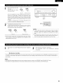
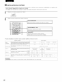
FOR ENGLISH READERS
•
•
PAGE
2 ~ PAGE
48, 94, 95
POUR LES LECTEURS FRANCAIS
We greatly appreciate your purchase of this unit.
To be sure you take maximum advantage of all the
features this unit has to offer, read these instructions
carefully and use the set properly. Be sure to keep this
manual for future reference should any questions or
problems
arise.
RECORD
2, 49
~ PAGE
95
Nous vous remercions pour I'achat de cet appareil.
Pour 6tre sQr de profiter au maximum de toutes les
caracteristiques qu'offre cet appareil, lire avec soin ces
instructions
et bien utiliser
I'appareil.
Toujours
conserver
ce mode
d'emploi
pour s'y
referer
ulterieurement
"SERIAL NO.
PLEASE
•
•
PAGE
en cas de question ou de probleme.
"NO. DE SERIE
UNIT
SERIAL
THE REAR OF THE CABINET
NUMBER
FOR FUTURE
ATTACHED
REFERENCE"
TO
PRIERE DE NOTER
LE NUMERO
DE SERIE DE L'APPAREIL
INSCRIT A L'ARRIERE DU COFFRET DE FA(_ON A POUVOIR
LE CONSULTER EN CAS DE PROBLEME."
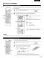
• SAFETY PRECAUTIONS
CAUTION
I"'mA
_RISK
TO PREVENT ELECTRIC SHOCK, MATCH WIDE BLADE OF PLUG
TO WIDE SLOT, FULLY INSERT.
OF ELECTRIC SHOCK
DO NOT OPEN
CAUTION:
ATTENTION
TO REDUCE THE RISK OF ELECTRIC SHOCK,
DO NOT REMOVE COVER (OR BACK). NO
USER-SERVICEABLE
PARTS INSIDE. REFER
SERVICING
TO
QUALIFIED
SERVICE
PERSONNEL.
POUR EVITER LES CHOCS ELECTRIQUES, INTERODUIRE LA
LAME LA PLUS LARGE DE LA FICHE DANS LA BORNE
CORRESPONDANTE
DE LA PRISE ET POUSSER JUSQU' AU
FOND.
The lightning
flash with
arrowhead
symbol,
within
an
equilateral triangle, is intended to alert the user to the
presence of uninsulated
"dangerous
voltage"
within the
product's enclosure that may be of sufficient magnitude to
constitute a risk of electric shock to persons.
•
•
Avoid
RELATIVES
the
set
following
including
complies
with
two
and
Part
15 of the
conditions:
(2) this
interference
This Class B digital
Interference-Causing
TO REDUCE THE RISK OF FIRE OR ELECTRIC
SHOCK, DO NOT EXPOSE THIS APPLIANCE
TO RAIN OR MOISTURE.
• NOTE ON USE / OBSERVATIONS
device
the
interference,
The exclamation point within an equilateral triangle is intended
to alert the user to the presence of important operating and
maintenance
(servicing)
instructions
in the literature
accompanying the appliance.
WARNING:
This
that
device
may
apparatus
Equipment
(1)
must
cause
FCC
This
Rules.
device
accept
Operation
may
any
undesired
not
interference
received,
toutes
of the Canadian
les exigences
A L'UTILISATION
•
Keep
dust.
free
from
•
Proteger Fappareit
poussi6re.
•
Unplug the power cord when
for long periods of time.
•
Debrancher
le cordon
d'aIimentation
Iorsque
Fappareit n'est pas utitise pendant de Iongues
contre
moisture,
water,
I'humidit6,
and
•
•
Do not let foreign
objects in the set.
Ne pas laisser
des objets
etrangers
Fappareil.
•
Do not let insecticides,
benzene,
come in contact with the set.
•
Ne pas mettre en contact des insecticides,
benz_ne et un diluant avec Fappareit.
•
Never
•
way.
Ne jamais
demonter
ou modifier
d'une maniere ou d'une autre.
dans
Feau et la
high temperatures.
Allow
for sufficient
installed
on a rack.
heat
Eviter
Tenir
elev6es.
dispersion
des temperatures
compte
d'une
suffisante
lors de Finstallation
dispersion
de
when
chaleur
sur une 6tag_re.
not using
the
set
and
thinner
du
p6riodes.
2
•
Handle the power cord carefully.
Hold the plug when unplugging
the cord.
•
Manipuler
le
pr6caution.
Tenir
la prise
cordon.
cordon
d'alimentation
avec
* (For sets with
Iors
du
debranchement
ventilation
holes)
du
•
Do not obstruct
the ventilation
•
Ne pas obstruer
les trous
holes.
d'aeration.
disassemble
to
harmful
operation.
meets all requirements
Regulations.
Cet appareil num6rique de la classe B respecte
Reglement sur le mat6riel brouilleur du Canada.
is subject
cause
or modify
the
set
in any
I'appareil
du
SAFETY INSTRUCTIONS
1.
Read
Instructions
instructions
should
operated.
be
All the
safety
and operating
read before
the appliance
is
2.
Retain Instructions
should be retained
-The safety and operating
for future reference.
3.
Heed Warnings - All warnings on the appliance
operating instructions
should be adhered to.
4.
Follow
should
5.
Water and Moisture - The appliance should not be used
near water - for example,
near a bathtub,
washbowl,
kitchen sink, laundry tub, in a wet basement,
or near a
swimming
pool, and the like.
6.
Carts and Stands -The appliance should be used only with
a cart or stand that is recommended
by the manufacturer.
6A.
An appliance and cart
combination
should be
moved with care.
Instructions
be followed.
- All operating
and
12.
Power-Cord
Protection
- Power-supply
cords should be
routed so that they are not likely to be walked on or
pinched by items placed upon or against them, paying
particular
attention
to cords
at plugs,
convenience
receptacles,
and the point where
they exit from the
appliance.
14.
Cleaning
- The appliance
should
recommended
by the manufacturer.
15.
Power Lines - An outdoor
from power lines.
16.
Outdoor
Antenna
Grounding - If an outside antenna is
connected
to the receiver, be sure the antenna system is
grounded so as to provide some protection against voltage
surges and built-up static charges. Article
810 of the
National
Electrical
Code,
ANSl/NFPA
70, provides
information
with regard to proper grounding of the mast
and supporting
structure, grounding of the leadqn wire to
an antenna-discharge
unit, size of grounding
conductors,
location of antenna-discharge
unit, connection to grounding
electrodes,
and requirements
for the grounding electrode.
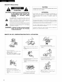
See Figure A.
17.
Nonuse Periods - The power cord of the appliance should
be unplugged from the outlet when left unused for a long
period of time.
instructions
and in the
use instructions
Quick stops, excessive
force, and uneven
surfaces may cause
the appliance and cart
combination
to overturn.
antenna
be cleaned
only
as
should be located away
7.
Wall or Ceiling
Mounting
mounted to a wall or ceiling
manufacturer.
- The appliance
should be
only as recommended
by the
18.
Object and Liquid Entry - Care should be taken so that
objects
do not fall and liquids are not spilled into the
enclosure through openings.
8.
Ventilation - The appliance should be situated so that its
location
or position
does not interfere
with its proper
ventilation.
For example,
the appliance
should not be
situated on a bed, sofa, rug, or similar surface that may
block the ventilation
openings;
or, placed in a built-in
installation, such as a bookcase or cabinet that may impede
the flow of air through the ventilation openings.
19.
9.
Heat - The appliance should be situated away from heat
sources such as radiators, heat registers, stoves, or other
appliances (including amplifiers) that produce heat.
Damage
Requiring
Service - The appliance
should be
serviced by qualified service personnel when:
A. The power-supply
cord or the plug has been damaged;
or
B. Objects have fallen, or liquid has been spilled into the
appliance; or
C. The appliance has been exposed to rain; or
D. The appliance does not appear to operate normally or
exhibits a marked change in performance;
or
E. The appliance
has been dropped, or the enclosure
damaged.
10.
Power Sources -The
appliance should be connected
to a
power supply only of the type described in the operating
instructions
or as marked on the appliance.
20.
11.
Grounding or Polarization - Precautions should be taken so
that the grounding or polarization means of an appliance is
not defeated.
Servicing - The user should not attempt
appliance
beyond
that described
in
instructions.
All other servicing
should
qualified service personnel.
to service the
the operating
be referred to
EXAMPLE
Ot'2##_AOROONDI._
AS
PER
ELECTRICAL
NATIONAL
CODE
ANTENNA
LEAD
IN
WIRE
GROUND
CLAMP
ANTENNA
DISCHARGE
(NEC
UNiT
SECTION
GROUNDING
EC
='1_
ELECTRICAL
CONDUCTORS
SECTION
810-21)
POWER
SERVICE
GROUNDING
ELECTRODE
SYSTEM
(NEC
NEC - NATIONAL
8t0-20)
ART
250,
PART
H)
CODE
3
• INTRODUCTION
Thank you for choosing the DENON A/V Surround receiver. This remarkable component has been engineered to provide superb surround sound
listening with home theater sources such as DVD, as well as providing outstanding high fidelity reproduction of your favorite music sources.
As this product is provided with an immense
contents of this manual before proceeding.
array of features, we recommend
that before you begin hookup and operation that you review the
TABLE OF CONTENTS
[]
Before Using ..............................................................................................
4
[]
Remote Control Unit ..........................................................................
22~24
[]
Cautions
on Installation
..............................................................................
5
[]
Operation
25~29
[]
Cautions
on Handling .................................................................................
5
[]
Surround .............................................................................................
30~34
[]
Features ......................................................................................................
5
[]
DSP Surround Simulation .........................................................
35~39
[]
Part Names and Functions .....................................................................
6, 7
[]
Listening to the Radio ........................................................................
40~42
[]
Read this first .............................................................................................
8
[]
Last Function Memory
[]
Setting up the Speaker Systems ................................................................
8
[]
Initialization
[]
Connections
[]
Additional
[]
Using the Remote Control Unit ................................................................
[]
Troubleshooting
[]
Setting up the system .......................................................................
.........................................................................................
9~15
16
17~21
...............................................................................
.............................................................................
of the Microprocessor
Information
Specifications
43
....................................................
........................................................................
43
44~46
........................................................................................
47
...........................................................................................
List of Preset Codes ..................................................................................
48
94, 95
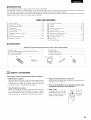
• ACCESSORIES
Check that the following
parts are included
(_ Operating instructions ............................................................................
Warranty ( for North America model only ) ............................................
(_ Service station list ...................................................................................
(_ Remote control unit (RC-897) .................................................................
®
2
1
1
1
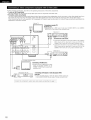
BEFORE USING
Pay attention
to the following
before using this unit:
• Moving the set
To prevent short circuits or damaged wires in the connection cords,
always unplug the power cord and disconnect the connection
cords between all other audio components when moving the set.
• Before turning the power operation switch on
Check once again that all connections are proper and that there are
4
_) R6P/AA batteries ....................................................................................
AM loop antenna ....................................................................................
(_ FM indoor antenna ..................................................................................
(_ FM antenna adaptor ................................................................................
®
%
!-_
1
1
1
1
in addition to the main unit:
• Store this instructions in a safe place.
After reading, store this instructions along with the warranty
safe place.
• Note that the illustrations in this instructions
the actual set for explanation purposes.
not problems with the connection cords. Always set the power
operation switch to the standby position before connecting and
%/,AUX terminal
disconnecting
equipped with a V. AUX terminal.
Remove the cap covering the
terminal when you want to use
it.
connection
cords.
The AVR-1802's
front
in a
may differ from
panel is
...........................
-
--_
j
t_
[_
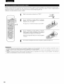
CAUTIONS
ON INSTALLATION
Noise or disturbance of the picture may be generated if this unit or
any other electronic equipment using microprocessors is used near a
tuner or TV.
If this happens, take the following steps:
• Install this unit as far as possible from the tuner or TV.
• Set the antenna wires from the tuner or TV away from this unit's
power cord and input/output connection cords.
• Noise or disturbance tends to occur particularly when using indoor
antennas or 300 _/ohms feeder wires. We recommend using
outdoor antennas and 75 _/ohms
coaxial cables.
0.3 ft (t0 cm) or more
For heat dispersal, leave at least 0.3 ft (10 cm) of space between
the top, back and sides of this unit and the wall or other
components.
eye CAUTIONS
• Switching
connected
the
ON HANDLING
input
function
when
input
jacks
are
not
• Whenever the power
state, the apparatus
A clicking noise may be produced if the input function is switched
when nothing is connected to the input jacks. If this happens,
either turn down the MASTER VOLUME control or connect
components
operation switch is in the STANDBY
is still connected on some AC line
voltages.
Please be sure to unplug the cord when you leave home for,
say, a vacation.
to the input jacks.
• Muting of PRE OUT
terminals
jack, HEADPHONE
jack and SPEAKER
The PRE OUT jack, HEADPHONE jack and SPEAKER terminals
include a muting circuit. Because of this, the output signals are
greatly reduced for several seconds after the power operation
switch is turned on or input function, surround mode or any other
set-up is changed.
If the volume is turned up during this time, the output will be very
high after the muting circuit stops functioning. Always wait until
the muting circuit turns off before adjusting the volume.
!-_
FEATURES
1. Dolby Pro Logic II decoder
Dolby Pro Logic ][][is a new format for playing multichannel audio
signals that offers improvements
over conventional
Dolby Pro
Logic. It can be used to decode not only sources recorded in
Dolby Surround but also regular stereo sources into five channels
(front left/right, center and surround left/right). In addition, various
parameters can be set according to the type of source and the
contents, so you can adjust the sound field with greater precision.
2. Dolby Digital decoder
Dolby Digital, a digital discrete system in which the different
channels
are completely
independent,
recreates
"threedimensional"
sound fields (sounds with a sense of distance,
4. High performance DSP simulates 7 sound fields
Playback is possible in 7 surround modes: 5-channel Stereo, Mono
Movie, Rock Arena, Jazz Club, Video Game, Matrix and Virtual.
You can enjoy a variety of sound effects for different movie
scenes and program
Dolby Surround.
specially-encoded
even with
stereo sources
not in
5. Personal Memory Plus function
Personal Memory
Plus is an advanced version of Personal
Memory. With Personal Memory Plus, the set automatically
memorizes
the surround
mode, channel volume, surround
parameters, etc., for each of the separate input sources.
6.
Remote control unit with pre-memory function
This unit comes with a remote control unit equipped with a prememory
function.
The remote control command
codes for
DENON remote controllable AV components as well as for DVD
players, LD players, video decks, TVs, etc., of other major
manufacturers are prestored in the memory.
7.
6CH EXT. IN jack
This unit is equipped with 6CH EXT. IN jacks for use with audio
formats of the future.
movement and position) with no crosstalk between channels for
greater reality. In addition, the 5 channels (excluding the 0.1
channel for low frequency
effects) have a playback range
extending to 20 kHz, the same as the range of CDs, thus resulting
in clearer, more richly expressive sound.
3. DTS (Digital Theater Systems) decoder
DTS provides up to 5.1 channels of wide-range, high fidelity
surround sound, from sources such as laser disc, DVD and
sources
music discs.
5
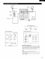
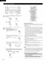
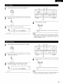
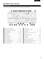
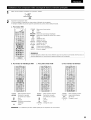
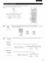
PART NAMES
AND FUNCTIONS
• For details on the functions of these parts, refer to the pages given in parentheses
().
DUD
Power operation switch ..............................................
(18, 25, 40)
Headphones jack (PHONES) ....................................................
(28)
Preset stations selector
(42)
buttons ..............................................
CH VOL button ........................................................................
_!_ MASTER VOLUME
(30)
control ......................................................
(27)
STATUS button ........................................................................
(28)
(28)
_l_ SPEAKER A/B buttons .................................................
(25, 28, 43)
_)
DIMMER
INPUT MODE button ...................................................
(26, 29, 33)
_)
Master volume indicator (VOLUME
button ......................................................................
ANALOG button ................................................................
(26, 29)
_1 Display
EXT. IN button ...................................................................
(26, 29)
_) TUNING UP/DOWN
LEVEL) ............................
button .....................................................
(41)
(33)
_1 MEMORY
_1_ TONE DEFEAT button .............................................................
(27)
_1 MODE button ..........................................................................
(41)
BAND button ...........................................................................
(41)
SIGNAL indicators ....................................................................
(27)
INPUT mode indicators ............................................................
(27)
VIDEO SELECT button ............................................................
_!_ V. AUX INPUT jacks .............................................................
SURROUND MODE button ...................................
(28)
(4, 10)
_}
(27, 31, 33, 38)
_)
SURROUND PARAMETER button .....................................
_)
SELECT knob ..................................................
button ...............................................................
(27)
_t_ CINEMA EQ button .................................................................
_)
(40, 42)
(31, 38)
_)
Remote control sensor (REMOTE SENSOR) .......................... (19)
(27, 30, 31, 33, 38)
_)
Power operation indicator
_!_ TONE CONTROL button ..........................................................
6
_)
(27)
Input source selector buttons .....................................
(26, 31, 33)
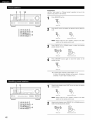
• For details on the functions of these parts, refer to the pages given in parentheses
(
Remote control signal
transmitter .........................................
I
f
CD
MD/CDR_
|
I Mode selector switch
I
I POWER buttons
__
V, AUX
,.IPHONO"
"'d6""
_
"gqg_5_"
_
VCR-1
VCR-2
(16)
I
(17, 22, 23)
.................... (23,24,25)
Input source selector
buttons ...................................
TV/DBS _
I
I
I
(26, 31, 33)
c_Dc_ oD.__j
INPUT MODE button
(26, 29)
SURROUND MODE
button ........................ (27, 30, 31, 33, 36)
System buttons (TAPE, VCR)
buttons .........................................
(22, 24)
I VIDEO SELECT button ....................... (28)
INPUT
MODE
_CDR/TAPE
I
I I
I I
'.._._._.
Preset stations select
buttons .........................................
Y
System buttons
(CD, MD/CDR, DVD/VDP) ............ (22, 24)
_i_iii
¸iii!iii!i!i
¸iii!!i,
SYSTEM (SYSTEM SET UP)
buttons ...............................................
I
(18)
I
I Cursor buttons ....................... {17,32,36)
I
I Test tone button .................................
(30)
I
I System buttons
(24)
I
(TV) ..........................
(22, 42)
I
I
I
_,STER
button
I
(SURROUND
..............................
PARAMETER)
(31, 33, 34, 36)
Master volume control
voL i
2',
SURROUND
buttons ...............................................
!
I MUTlNGbutton
--I
(27)
.................................
(28)
I
STATUS button ...................................
(28)
I
7
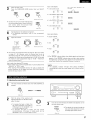
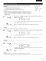
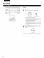
READ THIS FIRST
This AV Surround Receiver must be setup before use. Following these steps.
[
Next, insert the batteries
into the remote control unit.
Step 3
SETTING
•
UP THE SPEAKER
SYSTEMS
Speaker system layout
Basic system layout
• The following is an example of the basic layout for a system consisting of six speaker systems
and a television monitor:
Center speaker system
r
Front speaker systems
Set these at the sides of the TV or screen with
their front surfaces as flush with the front of the
screen as possible.
8
Surround
speaker systems
r_
CONNECTIONS
• Do not plug in the power cord until all connections have been
completed.
• Be sure to connect the left and right channels properly (left with
left, right with right).
• Insert the plugs securely. Incomplete connections will result in
the generation of noise.
• Use the AC OUTLETS for audio equipment
only. Do not
use them for hair driers, etc.
• Note that binding pin plug cords together with power cords or
placing them near a power transformer will result in generating
hum or other noise.
• Noise or humming may be generated if a connected audio
equipment is used independently
without turning the power
of this unit on. If this happens, turn on the power of this unit.
• Analog recording of signals input to the AVR-1802 in digital format is not possible. To record in analog, also connect the analog signals of the
player to the AVR-1802% analog input terminals.
• The AVR-1802's OPTICAL OUT terminal is an optical digital output terminal for connection of a CDR recorder, MD recorder or other digital
recording
I Connecting
device.
Use it for digital recording.
a turntable
I
Connect the turntable's
output cord to this
unit's PHONO jacks, the L (left) plug to the L
jack, the R (right) plug to the right jack.
NOTE:
This
unit
cannot
be
used
with
cartridges
directly. Use a separate
amplifier or step-up transformer.
INPUT
R
L
OUTPUT
R
L
Tape deck or CD recorder
[ Connecting
a tape
deck
I
Connections for recording:
Connect the tape deck's recording input jacks (LINE IN or REC) to this
unit's tape recording (OUT) jacks using pin plug cords.
Connections for playback:
Connect the tape deck's playback output jacks (LINE OUT or PB) to
this unit's tape playback (IN) jacks using pin plug cords.
MC
head
Z
If humming or other noise is generated when
the ground wire is connected, disconnect the
ground wire.
u.I
Z
{ Connecting
the pre-out
jacks 1
Use these jacks if you wish to connect external power amplifier(s) to increase the
power of the front and center channels, or for connection to powered !oudspeakers.
Connect the internal amplifier's subwoofer to the subwoofer
terminal. (Refer to
page 14.)
Tumtable
(MM cartridge)
AC 120V, 60Hz
°
%oo
Ground wire
,,
,,
L__._=_=_.
.... "1
®
®
(k
FRONT
®
®
CENTER
_
SURReUNO
®
_
SpEAKERSYSTEMS
_MACOUTLFS
i
I
w_
[ Connecting
LINE OUT
I
Ioo_O_
l
Decoders with 6-channel
analog outputs, etc.
AC_eV_
TOTSWITCHED
A
I
the AC OUTLETS 1
AC OUTLETS
SWITCHED
(total capacity - 120 W (1 A.))
The power to these outlets is turned on and off in conjunction
with the POWER switch on the main
unit, and when the power is switched between on and standby from the remote control unit.
No power is supplied from these outlets when this unit's power is at standby. Never connect
equipment whose total capacity is above 120 W (1 A.)
NOTE:
Only use the AC OUTLETS for audio equipment
Never use them for hair driers, TVs or other
electrical
appliances.
9
To connect the video signal, connect using a 75 _/ohms
video signal cable cord. Using an improper cable can result in a drop in sound quality.
I Connecting
a TV game equipment
• Connect the TV game equipment's
this unit's V. AUX INPUT lacks.
I Connecting
I
output jacks to
a video camera equipment
• Connect the video camera equipment's
jacks to this unit's V. AUX INPUT lacks.
"_ The V. AUX terminal is covered with a cap. Remove this cap in order to use the terminal.
10
(See page 4 for instructions
on removing
I
output
the cap.)
TV or DBS tuner
AUDIO
R OUT L
VIDEO
I Connecting
DIGITAL
OUT
OPTECAL
OUT
a TV/DBS
tuner
I
TV/DBS
• Connect the TV's or DBS tuner's video output jack (VIDEO OUTPUT)
to the _
(yellow) TV/DBS IN jack using a 75 _z!ohms video
coaxial pin plug cord.
• Connect the TV's or DBS tuner's audio output jacks (AUDIO
OUTPUT) to the _
TV/DBS IN jacks using pin plug cords.
out
_
AUDIO
.......
G
....
R°°TLOUT......
_
I Connecting
[] _EZD
oo::j_::
I
DVD player or video disc player (VDP)
a DVD player or a video disc player VDP I
• Connect the DVD player's (video disc player's) video output jack (VIDEO OUTPUT) to the _
(yellow) DVD/VDP
IN jack using a 75 _z!ohms video coaxial pin plug cord.
• Connect the DVD player's (video disc player's) analog audio output jacks (ANALOG AUDIO OUTPUT) to the
DVD/VDP IN jacks using pin plug cords.
• For better sound quality, we recommend using the DVD player with digital rather than analog connections.
DVD players and VDP can also be connected to the VCR terminals.
VIDEO
IN
_
Monitor
TV
MONITOR OUT
• Connect the TV's video input jack (VIDEO
INPUT) to the _
MONITOR OUT
jack using a 75 _/ohms video coaxial pin
plug cord.
@
@
(
VIDEO
@
OUT
@
€
_
VIDEO
IN
@
5
NOTE:
Connection of the video disc Player Equipped with Dolby Digital RF
(AC-3RF) Output Jack.
• Please use a commercially available adaptor when connecting the
Dolby Digital RF (AC-3RF) output jack of the video disc player to
the digital input jack.
Please refer to the instruction manual of the adapter when making
connections.
@
O
o
R OUT L
R
@
@
@
@
_N L
@
@
VIDEO
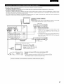
[ Connecting
a video decks
OUT
@
@
]
• There are two sets of video deck (VCR) jacks, so two video decks can be connected for simultaneous recording or video copying.
Video input/output
connections:
• Connect the video deck's video output jack (VIDEO OUT) to the _
(yellow) VCR-1 IN jack, and the video deck's video input jack (VIDEO IN) to the
(yellow) VCR-1 OUT jack using 75 _z!ohms video coaxial pin plug cords.
Connecting the audio output jacks:
• Connect the video deck's audio output jacks (AUDIO OUT) to the _
VCR-1 IN jacks, and the video deck's audio input jacks (AUDIO IN) to the _
OUT jacks using pin plug cords.
VCR-1
•_ Connect the second video deck to the VCR-2 jacks in the same way.
11
• When marking connections, also refer to the operating instructions of the other components.
• A note on the S input jacks
The input selectors for the S inputs and pin jack inputs work in conjunction with each other.
• Precaution when using S-jacks
This unit's S-jacks (input and output) and video pin jacks (input and output) have independent circuit structures, so that video signals input from
the S-jacks are only output from the S-jack outputs and video signals input from the pin jacks are only output from the pin jack outputs.
When connecting this unit with equipment that is equipped with S-jacks, keep the above point in mind and make connections according to the
equipment's instruction manuals.
Monitor TV
Connecting a monitor TV ]
MONITOR OUT
• Connect the TV's or DBS tuner's S video input (S-VIDEO INPUT) to the
MONITOR OUT jack using a S jack connection cord.
Video deck 1
I==== ....
_ ol O
I
_
I1_1
-[ Connecting the video decks ]
• Connect
S output
to the
VCR-1 INthe
jackvideo
and deck's
the video
deck'sjackS (S-OUT)
input jack
(S-IN)_ to the
VCR-1 OUT jack using S jack connection cords.
_
_
_R_T
SPEAKER
SYST_
®
_TER
oo
I
/
SURROUND
• Connect the video deck's S output jack (S-OUT) to the
VCR-2 IN jack and the video deck's S input jack (S-IN) to the
ACOUTL_S I
/AC120V_Hz
OHHHHOOOOOHHH_
_
VCR-2
OUT jack using
Video deck 2
I
HOOOOOOHH
j ,-.,-.,-.,-. ....
I
_
@ @j O
I1_1
--
_oooooo_ooooo_ooooo_ooooooo_oo_
TV or satellite broadcast tuner
I/[ 11
' a'v''-'
• Connect the TV's or DBS tuner's S video
output jack (S-VIDEO OUTPUT) to the
_
TV/DBS IN jack using an S jack
-
===
|
DVD player, VDP, etc.
connection
cord.
|
[ Connecting
a DVD player or video disc player (VDP) ]
DVD/VDP
• Connect the DVD player's or video disc player's S-Video output jack
to the S-VIDEO DVD/VDP IN jack using an S-Video connection cord.
Connect the components'
12
audio inputs and outputs as described on page 11. ]
S jack connection
cords.
DIRECTION OF
BROADCASTING
STATION
AM LOOP
ANTENNA
(An Accessory)
}_FM
ANTENNA
ANTEa_AZRMIN_LS_
75 _/ohms
COAXIAL
CABLE
_
CABLE
EEDER
# [_]
_
CDR/
L00P_
_ 2
FM ANTENNA
ADAPTER
(An Accessory)
AM OUTDOOR
ANTENNA
EXT_N
FM INDOOR
AUO_O
O_G_TAL
VlOEO
ANTENNA
(An Accessory)
GROUND
Connection
1. Push the lever.
of AM
antennas
2. insert the
conductor.
3. Return
the
lever.
=>
FM antenna adapter assembly
AM loop antenna assembly
Connect to the AM
antenna terminals.
Open the cover
SHUT
_Remove
the vinyl tie
and take out the
connection
line.
Bend in the reverse
direction.
PULL C
PUL
ANTENNA
ADAPTER
a. With the antenna
on top any stable
surface.
_
REMOVE
Mount
3C 2v
75 _/ohms
5C-2V
COAXIAL
CABLE
CLAMP
b. With the antenna
attached to a
wall.
Installation hole
Mount on wall, etc.
Note to CATV system installer:
This reminder is provided to call the CATV system installer's
attention to Article 820-40 of the NEC which provides guidelines
for proper grounding and, in particular, specifies that the cable
ground shall be connected
to the grounding system of the
building, as close to the point of cable entry as practical.
Notes:
• Do not connect two FM antennas simultaneously.
• Even if an external AM antenna is used, do not disconnect the
AM loop antenna.
• Make sure AM loop antenna lead terminals do not touch metal
parts of the panel.
13
• Connect the speaker terminals with the speakers making sure that like
polarities are matched (_) with @, _ with _). Mismatching
of polarities will
result in weak central sound, unclear orientation of the various instruments,
and the sense of direction of the stereo being impaired.
• When making connections, take care that none of the individual conductors
of the speaker cord come in contact with adjacent terminals, with other
speaker cord conductors, or with the rear panel.
Speaker
Impedance
• When speaker systems A and B are use separately, speakers with an
impedance of 6 to 16 _Uohms can be connected for use as front speakers.
• Be careful when using two pairs of front speakers (A + B) at the same time,
since use of speakers with an impedance of 12 to 16 _Uohms.
• Speakers with an impedance of 6 to 16 _Uohms can be connected for use
as center and surround speakers.
• The protector circuit may be activated if the set is played for long periods of
time at high volumes when speakers with an impedance lower than the
specified impedance are connected.
NOTE:
NEVER touch the speaker terminals when the power is on.
Doing so could result in electric shocks.
Connecting
the speaker cords
Connecting
1. Loosen by turning
counterclockwise,
2. Insert the cord.
banana plugs
3. Tighten by turning
clockwise.
banana plug
Turn clockwise
banana plug.
[FRONT
SPEAKER SYSTEMS
I
[FRONT
System B
i _EXX_N
AUII_O
SPEAKER SYSTEMS
I
[CENTER
to tighten,
SPEAKER SYSTEM
then insert the
I
System A
OI_ITAL
VIDEO
AOREIS_I_
__i!il
CENTER s_ _
hen connecting
speakers
s placed near a TV or video monitor, the
he screen may be disturbed
by the
agnetism. If this should happen, move
+
4-
Connection
jack for subwoofer
with
built-in
amplifier
(super woofer),
etc.
•_ To achieve
Dolby Digital
(AC-3) playback
effect,
use a unit
that can sufficiently
reproduce
frequencies
of under 80 Hz.
14
SURROUND
SPEAKER SYSTEMS
]
away to a position
have this effect.
where
it does not
This unit is equipped with a high-speed protection circuit. The purpose of this circuit is to protect the speakers under
circumstances such as when the output of the power amplifier is inadvertently short-circuited and a large current flows,
when the temperature surrounding the unit becomes unusually high, or when the unit is used at high output over a long
period which results in an extreme temperature rise.
When the protection circuit is activated, the speaker output is cut off and the power supply indicator LED flashes. Should
this occur, please follow these steps: be sure to switch off the power of this unit, check whether there are any faults with
the wiring of the speaker cables or input cables, and wait for the unit to cool down if it is very hot. Improve the ventilation
condition around the unit and switch the power back on.
If the protection circuit is activated again even though there are no problems with the wiring or the ventilation around the
unit, switch off the power and contact a DENON service center.
The protector circuit may be activated if the set is played for long periods of time at high volumes when speakers with
an impedance lower than the specified impedance (for example speakers with an impedance of lower than 4 O/ohms)
are connected. If the protector circuit is activated, the speaker output is cut off. Turn off the set's power, wait for the set
to cool down, improve the ventilation around the set, then turn the power back on.
15
_'_
USING
THE REMOTE
Following the procedure
CONTROL
UNIT
outlined below, insert the batteries
before using the remote control unit.
Point the remote control unit at the remote
control sensor as shown
on the diagram at the left.
NOTES:
• The remote control unit can be used from a straight distance of
approximately 23 feet/7 meters, but this distance will shorten or
operation will become difficult if there are obstacles between the
remote control unit and the remote control sensor, if the remote
30°
Approx
(_ Press as shown by the arrow and slide
off.
control sensor is exposed to direct sunlight or other strong light, or
if operated from an angle.
• Neon signs or other devices emitting pulse-type noise nearby may
result in malfunction, so keep the set as far away from such
devices as possible.
(_) Insert the R6P/AA batteries
shown on the diagram.
properly, as
(_ Close the lid.
NOTES:
•
•
•
•
Use only R6P/AA batteries for replacement.
Be sure the polarities are correct. (See the illustration inside the battery compartment.)
Remove the batteries if the remote control transmitter will not be used for an extended period of time.
If batteries leak, dispose of them immediately. Avoid touching the leaked material or letting it come in contact with clothing, etc. Clean the
battery compartment thoroughly before installing new batteries.
• Have replacement batteries on hand so that the old batteries can be replaced as quickly as possible when the time comes.
• Even if less than a year has passed, replace the batteries with new ones if the set does not operate even when the remote control unit is
operated nearby the set. (The included battery is only for verifying operation. Replace it with a new battery as soon as possible.)
16
SETTING
UP THE SYSTEM
• Once all connections with other AV components
have been completed as described in "CONNECTIONS"
various settings described below on the display.
These settings are required to set up the listening room's AV system centered around the this unit.
(see pages 9 to 15), make the
Set the slide switch to "AUDIO".
CD
MD/CDR
AUDIO_
2
Use the following
VIDEO
buttons
to set up the system:
t
i
t
SYSTEM
button
Press
this SETUP
to display
the system setup on the display.
I
I Press
CURSOR
(A, T,appears
_1, I_) on the display.
this buttons
change what
_
:MUTING
c3
Press this to switch the display.
i Also
SELECT
use button
this button to complete
the setting.
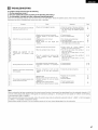
• System setup items and default values (set upon shipment from the factory)
System
Speaker
Configuration
Subwoofer
Mode
Delay_me
This selects
signals.
Default
Input
Channel Level
the
subwoofer
speaker
for
playing
deep
This assigns
sources.
Center Sp.
Large
Small
Subwoofer
Front & Subwoofer
the digital input jacks for the different
input
Digital
Inputs
Input
source
This adjusts the volume of the signals output from the speakers and
subwoofer
for the different
channels in order to obtain optimum
effects.
"HEADPHONE
COAXIAL
Front L
TV/DBS
Front R
OdB
OdB
Surround
Sp.
Small
mode
12 ft (3,6 m)
OPT[CAL-I
DVD/VDP
settings
Center
12 ft (3.6 m)
position.
NOTE:
• The system setup is not displayed when
Front Sp.
bass
This parameter
is for optimizing
the timing with which the audio
signals are produced from the speakers and subwoofer according to
the listening
Digital
setup
input the combination
of speakers
in your system
and their
corresponding sizes (SMALL for regular speakers, LARGE for full-size,
fuIFrange) to automatically
set the composition
of the signals output
from the speakers and the frequency response.
Sub Woofer
Yes
= Normal
Surround
L& R
10 ft (3.0 m)
w
w
OPTICAL-2
CDR/TAPE
Subwoofer
Center
OdB
0dB
Surround L
0riB
Surround R
0dB
w
w
ONLY" is selected.
17
1
Check that all the components are correct, then press the POWER operation switch on the main unit or
the POWER button on the remote control unit to turn on the power.
ON / STANDBY
AVR/AVC
%
(Main unit)
2
(Remote
control unit)
Press the SYSTEM button to enter the setting.
:+:SVSTEM
SET
NOTE: Please make sure the "AUDIO"
Press the SELECT or _
UF'
]
position of the slide switch on the remote control unit.
(down) button to switch to the speaker configuration
NOTE:
Press the SYSTEM button again to finish system set up. System set up can be finished at any time.
set up.
The changes to the settings
made up to
that point are entered.
1
Use the _
(left) and _
(right) buttons
to select your front speaker type.
_--_
(Initial)
IJ.
FROH[
L.i:::iRGE ]
_
EEl
OE]
(left) button
Press the SELECT or _
2
Use the _
(right) button
(down) button to switch to the center speaker setting.
(left) and _
(right) buttons
to select your center speaker type.
(Initial)
:2 CENTER
S Mi:::ii
.........
c_
c_
(left) button
Press the SELECT or C_
(right) button
(down) button to switch to the surround speaker setting.
NOTE:
• When "Small"
3
has been selected for the front speakers, "Large"
Use the _
(left) and _
cannot be selected for the center speaker.
(right) buttons
to select your surround speaker type.
(Initial)
3
:iii;U RR.
:iii;Mi:::ii
.........
(left) button
Press the SELECT or _
18
(down) button to switch to the subwoofer
setting.
(right) button
NOTE:
• When "Small"
has been selected for the front speakers, "Large"
4
Use the I_D (left) and _
:::i.
cannot be selected for the surround speakers.
(right) buttons
:::::
i:ii"ii"i
to select your subwoofer
i:::'i:::'i:;::
setting.
: -":"':....
E_D
(left) button
Press the SELECT or C_
(right) button
(down) button to enter the settings and switch to the SUBWOOFER
MODE
setting.
• Parameters
Large ......
Select this when using speakers that can fully reproduce
low sounds of below 80 Hz.
Small ......
Select this when using speakers that cannot reproduce low sounds of below 80 Hz with sufficient
selected, low frequencies of below 80 Hz are assigned to the subwoofer.
None ...... Select this when no speakers are installed.
Yes/No .... Select "Yes" when a subwoofer is installed, "No" when it's not installed.
volume.
When this setting
is
NOTE:
Select "Large" or "Small" not according to the physical size of the speaker, but according to the bass reproduction capacity at 80 Hz. If you cannot
determine the best setting, try comparing the sound when set to "Small" and when set to "Large", at a level that will not damage the speakers.
Caution:
In case the subwoofer is not used, be sure to set "Subwoofer
not reproduced in some mode.
1
Use the _
_U
(left) and _
= No", or the bass sound of front channel is divided to subwoofer
(right) buttons
to select the Subwoofer
_k,
channel and
mode.
(Initial)
.5 Si.-.i MO[?E NORM
'
'
(33
(left) button
Press the SELECT or (_D (down) button to enter
the setting
and switch
OD
(right) button
to the SPEAKER DISTANCE
setting.
NOTES:
-- Assignment of low frequency signal range -• The signals produced from the subwoofer channel are LFE signals (during playback of Dolby Digital or DTS signals) and the low frequency
signal range of channels set to "SMALL" in the setup. The low frequency signal range of channels set to "LARGE" are produced from those
channels.
-- Subwoofer
mode --
• The subwoofer mode setting is only valid when "LARGE" is set for the front speakers and "YES" is set for the subwoofer in the "Speaker
Configuration" settings (see pages 18, 19}.
If "SMALL" is set for the front speakers or "NO" is set for the subwoofer, the subwoofer mode setting does not affect playback of low
frequency signal range.
• When the "+MAIN" playback mode is selected, the low frequency signal range of channels set to "LARGE" are produced simultaneously
from those channels and the subwoofer channel.
In this playback mode, the low frequency range expand more uniformly through the room, but depending on the size and shape of the room,
interference may result in a decrease of the actual volume of the low frequency range.
• When the "NORM" playback mode is selected, the low frequency signal range of channels set to "LARGE" are only produced from those
channels. In this playback mode there tends to be little interference of the low frequency range in the room.
• Try playing the music or movie source and select the playback mode providing the stronger low frequency range sound.
19
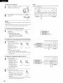
Input the distances from the listening position to the speakers and set the surround delay time.
Preparations:
Measure the distances from the listening position to the speakers (L1 to L3 on the diagram at the right).
L_: Distance from center speaker to listening position
L2: Distance from front speakers to listening position
L3: Distance from surround speaker to listening position
CAUTION:
•_ Set the center speaker at the same distance from the front speakers (left and right) or the subwoofer,
or so that the difference in distance (L2 - L1} is 5 feet or less.
•_ Set the surround speakers (left and right) at the same distance from the front speakers (left and right)
or the subwoofer, or so that the difference in distance (L2 - L3) is 15 feet or less.
1
Use the _
(left) and _
FL
L2 _,
SL
Center
FR
t' l
_tJ
Listening
SR
(right) buttons to set the distance from the front speakers and subwoofer
to the
listening position.
..... i'i'°::i"-i i ....::::0W
I':::
.........................
:i. 2
"i:'- i:]
:
• The number changes in units of 1 foot each time one of the buttons
to the measured distance.
("/SW"
appears only when subwoofer
is pressed. Select the value closest
= yes.)
Press the SELECT or (_D (down) button to switch to the center speaker setting.
NOTE:
• The speaker distance can be adjusted between
2
0 and 60 feet in steps of 1 foot.
Use the (_D (left) and _
position.
(right) buttons
' CENTER
to set the distance from the center speakers to the listening
:L2-i:--i::]
• The number changes in units of 1 foot each time one of the buttons
to the measured distance.
is pressed. Select the value closest
Press the SELECT or I_D (down) button to switch to the surround speaker setting.
NOTE:
• No setting when
"None"
3
has been selected for the center speaker.
Use the I_D (left) and I_
position.
(right) buttons
l:iii: :iii;URR.
to set the distance from the surround speakers to the listening
:i.0-i:i::]
• The number changes in units of 1 foot each time one of the buttons
to the measured distance.
is pressed. Select the value closest
Press the SELECT or (_D (down) button to enter the setting and switch the DIGITAL input (COAX) setting.
NOTE:
• No setting when
2O
"None"
has been selected for the surround speakers.
Input the type of components
connected
1
to the digital input terminals.
Use the C_
terminal.
(left) and _
(right) buttons to set the type of device connected to the COAXIAL input (COAXIAL)
(Initial)
9
C:0i:::i>::
[>i.i[> ]
_
(left) button
• Select "OFF"
2
_3
(right) button
if nothing is connected.
Press the SELECT or _
(down) button to switch the optical input 1 (OPT 1) setting.
Use the _
terminal.
(right) buttons to set the type of device connected to the OPTICAL input (OPTICAL)
(left) and _
(Initial)
:L0 0F:'T :L
'"',..,
(left) button
• Select "OFF"
3
(right) button
if nothing is connected.
Press the SELECT or C_
(down) button to switch the optical input 2 (OPT 2) setting.
Use the I_D (left) and I_
terminal.
(right) buttons to set the type of device connected to the OPTICAL input (OPTICAL)
(Initial)
:L:L 0 F:'T2
C[?R
]
(left) button
• Select "OFF"
if nothing is connected.
Press the SELECT or C_
NOTE:
(right) button
(down) button if you want to start the settings over front the beginning.
PHONO, TUNER and V. AUX cannot be selected.
1
This completes
Press the SYSTEM button to finish system set up.
the system setup operations.
or speakers are connected
Once the system is set up, there is no need to make the settings again unless other components
to or the speaker layout is changed.
21
_]
REMOTE
CONTROL
UNIT
DENON remote-controllable
audio components can be controlled using this unit's remote control unit.
Note that some components, however, cannot be operated with this remote control unit.
--1
v AUX VCml
Set the slide switch to the position for the component
be operated (CD or MD/CDR).
to
CD
AUDIO (_
MD/CDR
VIDEO
vcR.2 wJoBs
C_ I3D C_ 123
-2-e
2
Use the buttons shown below to operate the audio component.
For details, refer to the respective component's manual.
a,
For CD player and MD/CD
recorder
<141,1_1_ : Manual search (reverse and forward)
2-5--
•
:
I_
:
144,1_1_1 :
II
:
DISC SKIP+ :
=a-
Stop
Play
Auto search
Pause
Switch discs (for CD changers only)
b. For tape deck (TAPE)
Rewind
Fast-forward
DENON
Stop
Forward play
Reverse play
c. For TUNER
SHIFT
CHANNEL
Switch preset channel range
Preset channel up/down
(+, -)
NOTE:
• Tape deck (TAPE) and tuner can be operated when the switch is at "AUDIO"
position.
|
-1
VAUX VC_-I VC_-2 WJOBS
DENON components can be operated by setting the preset memory for MD or CDR.
Operation in not possible for some models.
1
Set the slide switch
to "MD/CDR".
CD
AUDIOL£_J
2
MD/CDR
VIDEO
Holding in the PLAY (1_) button, press the button for the
components you want to set. (Refer to table 1.)
Table 1: Combinations
Codes
GD
of Personal System
MASTER
VOL
PLAY (1_)
MASTER
VOL
(3D
CDR
NOTE:
• The memory can only be preset for either the MD or the CDR.
•_
Preset codes set upon shipment from the factory and when reset.
22
DENON and
This remote
manufacturer
Operation is
other makes of components can be operated by setting the preset memory for your make of video component.
control unit can be used to operate components of other manufacturers without using the learning function
of the component as shown on the List of Preset Codes (pages 94, 95).
not possible for some models.
Set the slide switch
to "VIDEO".
CD
by registering
the
MD/CDR
AUDIO_VlDEO
cD
MD_CDR
--1
-2
-3
2
Holding in the SHIFT button (_), press the POWER
button (_) of the components (DVD/VDP, VCR or TV) you
want to set.
-_ Press and hold in the SHIFT button.
-2.3
Holding (_)
in tothe
SHIFT
button code
(_), (consisting
press the ofnumber
buttons
input
the preset
2-digit
numbers)
for
the
manufacturer
of
the
(_)
component
_m__£._
_,_
whose
want94toand
store
memory.
See the signals
list onyou
pages
95 inforthethe
preset codes
(consisting
of 2-digit numbers).
_
_;3_
DENON
To continue registering
other components,
repeat steps 2 to 3.
NOTES:
• The signals for the pressed buttons are emitted while setting the preset memory. To avoid accidental operation, cover the remote control
unit's transmitting window while setting the preset memory.
• Some models and years of manufacture of components of the manufacturers listed on the List of Preset Codes cannot be used.
• The unit is equipped with several types of remote control codes which depend on the manufacturer. If there is no operation, please change
the preset code (a 2-digit number) and try again.
23
1
Set the slide switch to "VIDEO".
CD
MD/CDR
AUDIOI_VIDEO
2
Operate the video component.
• For details, refer to the component's operating instructions.
•_ Some models cannot be operated with this remote control unit.
a. For DVD player
POWER
: Turns power on and off
: Stop
II: Play
14141,I_1_1 : Auto search (cue)
4141,),4_ : Manual search (forward and reverse)
II
: Pause
TITLE
: Call out title
MENU
: Call out menu
DISPLAY : Switch display
SET UP : DVD setup
RETURN : Menu return
A,T
: Cursor up/down
_1,1_
: Cursor left/right
SELECT : Enter setting
cD
v AUX VC_-I VCR-2 TV/_aS
NOTE:
Some manufacturers use different names for the DVD remote control buttons,
instructions on remote control for that component.
so also refer to the
DENON
b. For video disc player
v AUX VCR4
POWER
441,1_I_
(VDP)
c. For video deck (VCR)
vc_-2 TV/UBS
: Power on/off
: Manual search
(forward and reverse)
•
: Stop
I_
: Play
144,1_1_1 : Auto search (cue)
II
: Pause
V AUX VCR-¢ VC_-2 TVJD_S
POWER
4141,I_1_
•
I_
II
CHANNEL
Power on/off
Manual search
(forward and reverse)
Stop
Play
Pause
: Switch channel
(+,-)
NOTE:
24
d. For monitor
The TV can be operated when the switch is at any position.
TV
V AUX VC_-I VCR-2 W_BS
POWER
VOLUME
Volume up/down
(A,v)
CHANNEL
Switch channel
(+, -)
Power on/off
r_l
OPERATION
Preparations:
Check that all connections
DE_ON
c_c_
_[_]
o_
O
o °
....
_
ooo-o
o o o o
o o o
1
are proper.
Turn on the power.
Press ON/STANDBY on the main unit or the AVR/AVC on the
remote control unit to turn on the power
ON / STANDBY
AVR/AVC
1
%
2
5@
(Main unit)
unit)
When the button is pressed, the power turns on and the
display lights after approximately 1 second.
When pressed again, the power turns off, the standby
mode is set and the display turns off.
Several seconds are required from the time the power
operation switch is set to the "ON" position until sound is
output. This is due to the built-in muting circuit that
prevents noise when the power switch is turned on and off.
CSD_
vA_x
(Remote control
• ON/STANDBY
VCR4 VCR-2
2
Select the front speakers.
Press SPEAKER A or B turn the speaker on.
SPEAKER
o
A
o
B
(Main unit)
25
1
5
V AUX VCR4
Lg___c_____csp_j
_ _-o
r_
0
o o o o o
o
o
--1
2-3--
_z__L£__--_:___c_J_
/
2
1
VCR-2 TV/UBS
_c_ c_ c_ c_
o
3
Press the button for the program source to be played.
EX 1: CD
CD
CD
%
(Main unit)
(Remote
control unit
EX 2: CDR/TAPE
CDR
%
%
(Main unit)
2
Input mode selection function
Different input modes can be selected for the different input sources.
The selected input modes for the separate input sources are stored
CDR/ TAPE
/ TAPE
(Remote
control unit
Select the input mode.
To select the input mode from main unit.
• Selecting the analog mode.
Press ANALOG to switch to the analog
input.
ANALOG
%
(Main unit)
• Selecting
the external
input (EXT. IN) mode.
(In this case play the component connected to the "EXT.
IN" terminal.)
Press EXT. IN to switch the external
Ex'r._N
input.
%
(Main unit)
• Selecting the AUTO, PCM and DTS modes.
The mode switches as shown below each time INPUT
MODE is pressed.
INPUT
MODE
t--oTsPCMJ
AUTO _
in the memory.
(_ AUTO (All auto mode)
In this mode, the types of signals being input to the digital and
analog input jacks for the selected input source are detected and
the program
in this unit's surround
decoder
is selected
automatically upon playback. This mode can be selected for all
input sources other than PHONO, CDR/TAPE and TUNER.
The presence or absence of digital signals is detected, the signals
input to the digital input jacks are identified and decoding and
playback are performed automatically in DTS, Dolby Digital or
PCM (2 channel stereo) format. If no digital signal is being input,
the analog input jacks are selected.
Use this mode to play Dolby Digital signals.
(_) PCM (exclusive PCM signal playback mode)
Decoding and playback are only performed when PCM signals are
being input.
Note that noise may be generated when using this mode to play
signals other than PCM signals.
(_) DTS (exclusive DTS signal playback mode)
Decoding and playback are only performed when DTS signals are
being input.
(_ ANALOG (exclusive analog audio signal playback mode)
The signals input to the analog input jacks are decoded
played.
(_ EXT. IN (external decoder input jack selection mode)
and
The signals being input to the external decoder input jacks are
played without passing through the surround circuitry.
NOTE:
(Main unit)
To select the input mode from the remote control unit,
• The mode switches as shown below each time INPUT
MODE is pressed.
AUTO -_
PCM ---_ DTS -_ANALOG
I
EXT. IN =
INPUT
MODE
%
(Remote control
26
unit)
I
• Note that noise will be output when CDs or LDs recorded in DTS
format are played in the "PCM" (exclusive PCM signal playback) or
"ANALOG" (exclusive analog audio signal playback) mode. Select
the AUTO or DTS (exclusive DTS signal playback) mode when
playing signals recorded in DTS from a laser disc player.
Notes on playing a source encoded with DTS
• Noise may be generated at the beginning of playback and
while searching during DTS playback in the AUTO mode. If
so, play in the DTS mode.
• In some rare cases noise may be generated when you preform
the operation to stop playback of a DTS-CD or DTS-LD.
3
Select the play mode.
Press the SURROUND
knob.
Input mode display
MODE
button,
then
turn SELECT
SELECT
%
lights,
depending
on the
_NPUT
AUTO
o
%
(Main unit)
(Remote control
•_ To select the surround mode while adjusting
the surround parameters, channel volume or
tone control, press the surround
button then operate the selector.
PCM
_
SURROUND
MODE
SURROUND
MODE
One of these
input signal.
• In the AUTO mode
OTS
o
o
• In the DIGITAL PCM mode
INPUT
AUTO
P_M z
O
unit)
O
• In the DIGITAL DTS mode
SURROUND
MODE
mode
DTS
_@C
INPUT
DTS
PCM
AUTO
o
o
_'o
• In the ANALOG mode
iNPUT
(Main unit)
4
Start playback on the selected component.
• For operating
instructions,
refer to the
manual.
component's
AUTO
PCM
DTS
O
O
O
Input signal display
• DOLBY DIGITAL
Adjust the volume.
_
MASTER
S+GNAL
D+GtTAL
VOLUME
_'p.
o
• DTS
_
The volume
level is
(Main unit)
(Remote control
displayed on the
master volume level
S+GNAL
DIGITAL
unit)
o
_e
• PCM
display.
_
S+GNAL
DIGITAL
•_ The volume can be adjusted within the range of -60 to 0 to 18 dB,
in steps of 1 dB. However, when the channel level is set as
described on page 30, if the volume for any channel is set at +1 dB
or greater, the volume cannot be adjusted up to 18 dB. (In this case
the maximum volume adjustment range is "18 dB -- (Maximum
value of channel level)".)
Input mode when playing DTS sources
• Noise will be output if DTS-compatible
"ANALOG" or "PCM" mode.
CDs or LDs are played in the
When playing DTS-compatible sources, be sure to connect the
source component to the digital input jacks (OPTICAL/COAXIAL)
and set the input mode to "DTS'.
[1] Adjusting
1
O
•_ The _
indicator lights when digital signals are being input
properly. If the _
indicator does not light, check whether
the digital input component setup (page 21) and connections are
correct and whether the component's power is turned on.
NOTE:
• The _
containing
heard.
The tone switches
as follows
each time TONE CONTROL is
DENON
pressed.
%
o
the
name of the volume
_
O
_[_)
o
o °
o
o
o
o
o
o
o
o
1
_
o
o
BASS_TREBLE
(Main unit)
With
indicator will light when playing CD-ROMs
data other than audio signals, but no sound will be
the sound quality (tone)
TONE
CONTROL
2
O
D
O
_
to be
adjusted selected, turn SELECT knob to
adjust the level.
.....
3
_=_t_
2
z
1
SELECT
O
• To increase the bass or treble: Turn
the control clockwise. (The bass or
(Mainunit)
treble sound can be increased to up
to +12 dB in steps of 2 dB.)
• To decrease
the bass or treble:
Turn the control
counterclockwise.
(The bass or treble sound can be
decreased to up to -12 dB in steps of 2 dB.)
3
If you do not want the bass and treble to be adjusted, turn on
the tone defeat mode.
TONE DEFEAT
•_ The signals do not pass through the
bass and treble adjustment circuits,
providing higher quality sound.
(Main unit)
27
NOTE:
[2] Listening over headphones
To prevent hearing loss, do not raise the volume
when using headphones.
PHONES
level excessively
Connect
the ofheadphones
to the
PHONES jack
the front panel.
DENON
o
_
_o
o-o
o
o
o
o
o
_2
2-22
2
-
-
-
=
sos
Press
A or B to
speakerSPEAKER
off.
turn the
OASPEAKER
OB
r_i_-]".....
2
Cautions:
• No sound is produced from the headphones when speakers A or B
are turned on.
• When an external power amplifier is connected to the front preout
jacks, turn off the external power amplifier's speaker switch.
[3] Turning the sound off temporarily
1
(muting)
Use this to turn off the audio output
temporarily.
Press MUTING.
•_ Cancelling MUTING mode.
Press the MUTING button again.
Muting mode will also be cancelled
when MASTER VOL is adjusted up
or down.
MUTING
%
[4] Combining the currently playing sound with the desired image
1
Simulcast playback
Use this switch
to monitor a
MIDEOSELECT
00000
audio source.
video VIDEO
source SELECT
other than the
Press
repeatedly until the desired
source
appears on the
%
%
(Main unit)
(Remote control unit)
display.
•_ Cancelling simulcast playback.
• Select "SOURCE" using the video select button.
• Switch the program source to the component connected
1
to
the video input.
[5] Checking the currently playing program source, etc.
1
operations are also
displayed on the front
panel display. In addition,
the display can be
switched to check the
unit's operating status
while playing a source by
pressing STATUS.
2
©
Front panel display
• Descriptions of the unit's
STATUS
303
(Main unit)
Using the dimmer function
• Use this to change the brightness
(Remote control unit)
2
of the
The
display brightness changes in four
display.
steps (bright, medium, dim and off) by
DIMMER
%
pressing the main unit's DIMMER
(Mainunit)
repeatedly.
•_ The brightness changes in 3 steps each time the button is
pressed, and finally the display turns off.
28
oooo
&ly
m
1
1
Set the external
input (EXT.
Press the EXT. IN to switch
the external input.
_'T._N
INPUTMODE
%%
(Main unit)
DENON
o
(Remote control unit)
_
O
_
o
Once this is selected, the input signals connected to the FL
(front left), FR (front right), C (center), SL (surround left), and
o
o
o
o
o
o
o
o
o
o
o
_O_
|
SR (surround right) channels of the EXT. IN jacks are output
directly to the front (left and right), center, surround (left and
__
_1
2 1
right) speaker systems without passing through the surround
circuitry.
In addition, the signal input to the SW (subwoofer) jack is
output to the PRE OUT SUBWOOFER jack.
2
o °
Cancelling the external input mode
To cancel the external input (EXT. IN) setting, press the INPUT
MODE (AUTO, PCM, DTS) or ANALOG button to switch to
the desired input mode. (See page 26.)
INPUT MODE
ANALOG
%%
(Main unit)
NOTES:
INPUT MODE
%
(Remote
control
• In play modes other than the external input mode, the signals
connected to these jacks cannot be played. In addition, signals
cannot be output from channels not connected to the input
unit)
jacks.
• The external
• When the input mode is set to the external input (EXT. IN), the play
mode (STEREO, DOLBY/DTS SURROUND, 5CH STEREO or DSP
SIMULATION) cannot be set.
1
Follow step 1 to 3 under "Playing the input source" (page 26,
27).
Simultaneous
input mode can be set for any input source.
To
watch video while listening to sound, select the input source to
which the video signal is connected, then set this mode.
fJ
L
Start recording on the tape or video deck.
For instructions,
refer
to the component's
instructions.
operating
recording
The signals of the source selected with the function selector button are output simultaneously to the CDR/TAPE and VCR REC OUT jacks. If
a total of two tape and/or video decks are connected and set to the recording mode, the same source can be recorded simultaneously on
every decks.
NOTES:
• The AUDIO IN's signal selected with the function selector button are output to the CDR/TAPE and VCR AUDIO OUT jacks.
• The DIGITAL IN's signal selected with the function selector button are output to the DIGITAL OUT (OPTICAL) jack.
29
I'_
SURROUND
• Before playing with the surround function, be sure to use the test tones to adjust the playback level from each speakers. This adjustment
be performed from the remote control unit, as described below.
• The adjustment with the test tones is only effective in the DOLBY/DTS SURROUND modes.
The adjusted playback levels for the different surround modes are automatically stored in the memory of each surround modes.
1
Set the DOLBY/DTS SURROUND (Dolby Pro Logic II or Dolby
Digital or DTS) modes.
1__o_._
SURROUND
MODE
SELECT
_o
%
0
(Main unit)
2
can
(Remote control
ooo]
0
CD
C3
2
unit)
2,
I
Press T. TONE button.
II
2
(Remote control
unit)
(Remote control
unit)
3
After completing
the adjustment,
press T. TONE button again.
Test tones
are output
from
the
different speakers. Use the channel
volume adjust buttons to adjust so
that the volume of the test tones is
the same for all the speakers.
(Remote
control unit)
NOTE" Please make sure the "AUDIO" position of the slide
switch on the remote control unit.
• After adjusting using the test tones, adjust the channel levels either according to the playback sources or to suit your tastes, as described below.
1
Select the speaker whose level you want to adjust.
DENON
OH VOL
0
(Main unit)
(Remote control
_
0
0
0
0
0
0
0
0
0
0
unit)
o
The channel switches
0
_
.....
_
_(_
as shown below each time the button
is pressed.
2
4
NOTE" Please make sure the "AUDIO" position of the slide
switch on the remote control unit.
m
2
Adjust the level of the selected speaker.
m
2--
(Main unit)
(Remote control
unit)
•_ The level of the selected speaker can be adjusted within
the range of +12 to -12 dB using the SELECT (up and
down) buttons.
3O
1
1
Select the function to which the component
is connected.
you want to play
_ENON
EX:
DVD / VDP
DVD/VDP
%
(Main unit)
2
(Remote
Select the Dolby Surround
Select the DOLBY PRO
LOGIC ][][mode using the
SELECT knob.
control unit)
o
00000000
o
o
_'-----_--"
1
Pro Logic ][][mode.
The surround mode
switches when the
SURROUND MODE button
is pressed. Select the
DOLBY PRO LOGIC ][][
mode.
SURROUND
MODE
SELECT
%
(Main unit)
:-,;-£_;£vcR._ vc_.2 WJDBS
!
_CZ3[-Q C_ CZ3_
(Remote control unit)
• The Dolby Pro Logic indicator lights.
Display
Light
[X}LB'-i
F'L :[ :[
Dr]PR0 LOGIC
4,5,6,7--
PL. ZZ C DUD
3
4
Play a program source with the r3rll=_u_fsU_NOl
mark.
• For operating
instructions,
refer to the manuals of the respective components.
Select the surround
DENON
parameter mode.
Display
SURROUND
PARAMETER
(Main unit)
(Remote
control unit)
•_ To perform this operation from the remote control unit,
check that the mode selector switch is set to "AUDIO".
Set the surround
parameters according to the mode.
SURROUND
PARAMETER
5
Select the optimum
mode for the source.
(Main unit)
• The mode switches
(Main unit)
(Remote
control unit)
(Remote control
is pressed.
--="MODE CINEMA
i"ifi[)E i::'i:;:i]i L0G :[C i"i0[:,E i]:]]i..iE:Hi:_[i"i0[)E i"iUS:[C]
SELECT
l0
_
or(_
_
(_or
SELECT
0 )-
unit)
as shown below each time the button
CINEMA EQ
_MODE
PRO LOGIC
DEFAULT
I
--_ MODE MUSIC
CINEMA EQ
PANORAMA
DEFAULT
DIMENSION
I
CENTER WIDTH
DEFAULT
31
7
Set the various surround parameters.
NOTE:
• CINEMA EQ setting
• When making parameter settings, the display will return to the
regular condition several seconds after the last button was
pressed and the setting will be completed.
C i N E H Fi Ei:;:! 0 F F
Surround
SELECT
_
or
• PANORAMA
SELECT
C orO
setting
F'i:::i['.i0 [;;:i:::i
H i:::i i:)F F
_O- or_
• DIMENSION
(_
or_O_
required
mode for all A / V
as the standard
mode
for
setting
This mode extends the front stereo image to include the surround
speakers for an exciting "wraparound"
effect with side wall
[) i i,iE i..i'.iii;
i 0 i..i 3
imaging.
Select "OFF" or "ON".
SELECT
_
_
_O orC_
SELECT
_orO_
• CENTER WIDTH setting
orS
• DEFAULT setting
[) E Fi:::iU L T
"Yes" to reset
V/N
to the factory
Control:
This control gradually adjust the soundfield
or towards the rear.
either towards the front
The control can be set in 7 steps from o to 6.
Center Width Control:
This control adjust the center image so it may be heard only from
the center speaker; only from the left/right speakers as a phontom
image; or from all three front speakers to varying degrees.
The control can be set in 8 steps from 0 to 7.
C E i..iT E R i.,ii [)T H 0
defaults.
•_ Stop pressing buttons once you have completed
setting the
surround parameters.
After several seconds the normal display
reappears and the settings you have made are automatically set.
32
(_
autosound music systems (no video), and is optional for A / V
systems.
The Pro Logic mode offers the same robust surround processing
as original Pro Logic in case the source contents is not of optimum
quality.
Select one of the modes ("Cinema",
"Music" or "Pro Logic").
Panorama Mode:
Dimension
•_ Select
parameters
Pro Logic 1] Mode:
The Cinema mode is the standard
systems.
The Music mode is recommended
1
Select the input source.
1
3
I Playback with a digital input I
(_ Select an input source set to digital (COAXIAL/OPTICAL)
(see page 21 ).
[......
o:
EX:
o
DVD / VDP
_t_
o
I
o
o
o
o
o
o
DVD/VDP
+
r_ o
+
__T__T _
t
(Main unit)
(Remote
control unit)
1
(_) Set the input mode to "AUTO"
INPUT MODE
2
INPUT MODE
%
%
(Main unit)
2
2
4
or DTS.
(Remote
control unit)
--1
Select the Dolby/DTS Surround mode.
SURROUND
MODE
m
%
(Remote control
2--
unit)
When performing this operation from the main unit's panel,
press SURROUND MODE, then turn SELECT knob and select
"DOLBY/DTS".
• The following appears on the display. (DOLBY PL ][][, PRO
LOGIC, DOLBY DIGITAL, DTS SURROUND)
--4,5,6,7
4,5,6,7--
DENON
SURROUND
MODE
SELECT
%
0
(Main unit)
3
Play a program source with the
uu
4
mark.
• The Dolby Digital indicator lights when
DIGITAL
_O_--
Drll-m----------I
_
DIQITAL
Light
• The DTS indicator lights when playing
DTS sources.
playing Dolby Digital sources.
Set the surround parameter according to the source.
First, press the SURROUND button.
NOTE:
The CINEMA EQ mode can be set directly using the main
unit's CINEMA EQ button.
Please make sure the "AUDIO"
position of the slide switch on the
remote control unit.
(Remote
control unit)
I C 1[N Ei:ii:::i Ei]:! OF F
Use _
(left) and _
set the CINEMA EQ.
]
CINEMA EQ
%
• CINEMA EQ mode turns on and off
each times the CINEMA EQ button
is pressed.
(Main unit)
(right) buttons to
(Initial)
(Remote
control unit)
c_
(left) button
oi3
(right) button
33
Press SURROUND or CE) (down) button to switch to the D.COMR setting.
(Remote
control unit)
5
Use _
(left) and _
(right) buttons to set the D. COMR
(Initial)
(Remote
:"-.
control unit)
:"- :": --'-.-:
:":
:": C"C"
EE)
%%
Press SURROUND or _
(down) button to switch to the LFE setting.
(Remote controlunit)
(right) button
NOTE:
This parameter
is not
displayed
during DTS playback.
Use _
(left) and _
(right) buttons to set the LFE level.
.....
F::E
(Remote
OD
(left) button
i?.i
,:::i
B
control unit)
%%
• The level can be adjusted in units of 1 dB from -10 to 0 dB.
Set to the desired level according to the speaker systems being used and the source to be played.
Press SURROUND or _
(down) button to switch to the default setting.
(Remote controlunit)
7
To reset the settings to the factory defaults, use I:_
[::"E: F:: i:::iU L 'i
(Remote
(left) and _
(right) buttons to display "Yes".
:-:-.--"i--i
(3D
control unit)
(left) button
%%
Press SURROUND or C_
0_3
(right) button
(down) button to switch to the CINEMA EQ. setting.
(Remote controlunit)
NOTE:
• When making parameter settings, the display will return to the regular condition several seconds after the last button was pressed and the
setting will be completed.
Surround parameters
CINEMA EQ. (Cinema Equalizer):
The Cinema EQ function gently decreases the level of the extreme high frequencies, compensating
soundtracks. Select this function if the sound from the front speakers is too bright.
This function only works in the Dolby Pro Logic, Dolby Digital and DTS Surround modes.
for overly-bright
sounding motion picture
D.OOMP. (Dynamic Range Compression}:
Motion picture soundtracks have tremendous dynamic range (the contrast between very soft and very loud sounds). For listening late at night,
or whenever the maximum sound level is lower than usual, the Dynamic Range Compression allows you to hear all of the sounds in the
soundtrack (but with reduced dynamic range). (This only works when playing program sources recorded in Dolby Digital.) Select one of the four
parameters ("OFF", "LOW", "MID" (middle) or "HI" (high)). Set to OFF for normal listening.
LFE (Low Frequency Effect}:
Program source and adjustment range
1. Dolby Digital: -10 dB to 0 dB
2. DTS Surround: -10 dB to 0 dB
-_ When Dolby Digital encoded software is played, it is recommended that the LFE LEVEL be set to 0 dB for correct Dolby Digital
playback.
-_ When DTS encoded movie software is played, it is recommended that the LFE LEVEL be set to 0 dB for correct DTS playback.
•_ When DTS encoded music software is played, it is recommended that the LFE LEVEL be set to -10 dB for correct DTS playback.
34
I'_
DSP SURROUND
SIMULATION
• This unit is equipped with a high performance DSP (Digital Signal Processor) which uses digital signal processing to synthetically recreate the
sound field. One of 7 preset surround modes can be selected according to the program source and the parameters can be adjusted according
to the conditions in the listening room to achieve a more realistic, powerful sound. These surround modes can also be used for program sources
not recorded in Dolby Surround Pro Logic or Dolby Digital.
1
5CH STEREO
In this mode, the signals of the front left channel are output from the left surround channel, the signals of the front
right channel are output from the right surround channel, and the same (in-phase) component of the left and right
channels is output from the center channel. This mode provides all speaker surround sound, but without directional
steering effects,
and works with any stereo program source.
2
MONO MOVIE
(NOTE 1)
Select this when watching
monaural movies for a greater sense of expansion.
3
ROCK ARENA
Use this mode to achieve the feeling of a live concert in an arena with reflected sounds coming from all directions.
4
JAZZ CLUB
This mode creates the sound field of a live house with a low ceiling and hard walls. This mode gives jazz a very
vivid realism.
5
VIDEO GAME
Use this to enjoy video game sources.
6
MATRIX
Select this to emphasize the sense of expansion for music sources recorded in stereo. Signals consisting of the
difference component of the input signals (the component that provides the sense of expansion) processed for
delay are output from the surround channel.
7
VIRTUAL
Select this mode to enjoy a virtual sound field, produced from the front 2-channel speakers.
•_ Depending on the program source being played, the effect may not be very noticeable.
In this case, try other surround modes, without worrying about their names, to create a sound field suited to your tastes.
NOTE 1: When playing sources recorded in monaural, the sound will be one-sided if signals are only input to one channel (left or right), so input
signals to both channels. If you have a source component with only one audio output (monophonic camcorder, etc.) obtain a "Y" adaptor
cable to split the mono output to two outputs,
and connect to the L and R inputs.
NOTE:
Only the STEREO mode can be used when playing PCM signals with a sampling frequency of 96 kHz (such as from DVD-Video discs that
contain 24 bit, 96 kHz audio). If such signals are input during playback in one of the other surround modes, the mode automatically switches
to STEREO.
If the DTS signals are input during playback in VIRTUAL surround mode, the mode automatically
switches
to STEREO.
Personal Memory Plus
This set is equipped with a personal memorize function that automatically memorizes the surround modes and input modes selected for the
input different sources. When the input source is switched, the modes set for that source last time it was used are automatically recalled.
-_ The surround parameters,
surround mode.
tone control
settings
and playback
level balance for the different
output channels
are memorized
for each
35
• To operate the surround mode and surround
1
Select the surround
parameters from the remote control unit.
mode for the input channel.
SURROUND
MODE
%
(Remote
v Aux
The surround mode switches in the following order each time
the SURROUND MODE button is pressed:
_STEREO
_
[_,-MONO
DOLBY PRO LOGIC _
MOVIE _ROCK
sV/RT_AL
D_
2
CLUB,
setting mode, press the SURROUND button.
• The surround parameter switches
different surround modes.
control unit)
i
V,DEO GAME
To enter the surround parameter
(Remote
vcR.2 TWBS
5CH STEREO •
ARENA_JAZZ
MATRIX _
vcR.l
IZ3 I:ZD I-Q I-Q
control unit)
•
•
•
•
in the following
ROCK ARENA
JAZZ CLUB
VIDEO GAME
MONO MOVIE
order each time the SURROUND
• MATRIX
button is pressed
• VIRTUAL
EFFECT I _,_ULT
I _,_ULT
DEFAULT
3
Display the parameter you want to adjust, then use the _
(left) and _
(right) buttons to set it.
(1) ROOM SIZE
Use the I_D (left) and _
(right) buttons to set the room size.
(Initial)
ROOH
:iii:
:i::i:iiii:
i,iiiii:i:?
(Remote
(23
control unit)
_D
(left) button
(right) button
(2) EFFECT LEVEL
Use the I_D (left) and (_
(right) buttons to set the effect level.
EF::F::
Ei::::T L Ei...i
Ei.... i i?.il
I
(Remote
control unit)
(Initial)
_
GD
(left) button
36
_
(£3
(right) button
for the
(3) DELAY TIME
Use the _
(left) and _
(right) buttons to set the delay time.
(Initial)
,...-,....,....,"":"
::--,, :::.!:_ii._,,,:_:____
(Remote
(33
control unit)
(3D
(left) button
(right) button
(4) DEFAULT
To reset the settings to the factory defaults, use the _
(left) and _
I[::,EF::i:::iUL.T'-,-,"HI
(Remote
control unit)
(right) buttons to display "Yes".
_
(33
(left) button
8D
(right) button
NOTE:
• When making parameter settings, the display will return to the regular condition several seconds after the last button was pressed and the
setting will be completed.
37
• Operating the surround
1
mode and surround parameters from the main unit's panel.
Turn the SELECT knob to select the surround mode.
DENON
_
O
_
o
o o
SELECT
o
o
o
o
o
o
o
o
o
o
o
(Main unit)
1 21,3
• When turned clockwise
• When turned counterclockwise
+0,: STE ,+Iow
OOV
E O.O
•_ To select the surround mode while adjusting the surround
button then operate the selector.
parameters,
channel volume or tone control,
press the surround
mode
SURROUND
MODE
%
(Main unit)
2
Press SURROUND
PARAMETER.
Press and hold in the surround parameter button to select the parameter you want to set.
• The parameters which can be set differ for the different surround modes. (Refer to "Surround
Modes and Parameters"
on page 39.
SURROUND
PARAMETER
%
(Main unit)
Display the parameter you want to adjust, then turn the SELECT knob to set it.
NOTE:
• When playing PCM digital signals or analog signals in the 5CH STEREO, ROCK, ARENA, JAZZ CLUB, VIDEO GAME, MONO
MATRIX surround modes and the input signal switches to a digital signal encoded in Dolby Digital, the Dolby surround
automatically. When the input signal switches to a DTS signal, the mode automatically switches to DTS surround.
38
MOVIE or
mode switches
Surround parameters
ROOM SIZE:
This sets the size of the sound field.
There are five settings: "small", "med.s"
field, "large" a large sound field.
(medium-small),
"medium",
"med.l"
(medium-large)
and "large".
"small"
recreates a small sound
EFFECT LEVEL:
This sets the strength of the surround effect.
The level can be set in 15 steps from 1 to 15. When the surround
Lower the level if the sound seems distorted.
mode is set to "VIRTUAL",
the effect level can be set in steps from 1 to 10.
DELAY TIME:
In the matrix mode only, the delay time can be set within
•
the range of 0 to 110 ms.
Surround modes and parameters
Channel
Mode
FRONT L/R
output
When
CENTER
SURROUND
L/R
SUBWOOFER
playing
Dolby
When
playing
DTS
When
playing
PCM
When
playing
ANALOG
Digital
signals
signals
signals
signals
STEREO
O
x
×
@
O
O
O
O
EXTERNAL INPUT
O
@
@
@
×
x
×
0
DOLBY
PRO LOGIC ][][
O
@
@
@
x
O
O
DOLBY
DIGITAL
O
@
@
@
O
x
×
×
DTS SURROUND
O
@
@
@
×
O
×
×
5CH STEREO
O
@
@
@
×
x
O
O
ROCK ARENA
O
@
@
@
×
x
O
O
JAZZ CLUB
O
@
@
@
×
x
O
O
VIDEO GAME
O
@
@
@
×
x
O
O
MONO
O
@
@
@
×
x
O
O
MATRIX
O
@
@
@
×
x
O
O
VIRTUAL
O
x
×
@
O
x
O
O
MOVIE
O :
Signal
O :
Able
x
@
No signal
× :
Unable
Turned on or off by speaker
configuration
Mode
STEREO
ROOM
SIZE
2 ch contents.
(default values are shown
in parentheses)
PARAMETER
PRO LOGIC ][][MUSIC
TONE
CONTROL
for
setting
Parameter
SURROUND
* Only
MODE
ONLY
EFFECT
LEVEL
DELAY
TIME
MODE
PANORAMA
DIMENSION
CENTER
WIDTH
x
x
×
×
Dolby Digital signals
CINEMA
EQ
x
DTS signals
D.COMP
LFE
LFE
O (OFF)
O (OdB)
O (0dB)
×
×
X
O (OFF)
O (OdB)
O (0dB)
×
×
×
EXTERNAL INPUT
O (0dB)
×
×
×
X
X
×
×
X
DOLBY
PRO LOGIC ][][
O (0dB)
×
×
×
O (CINEMA)
O (OFF)
O (3)
O (O)
O (OFF)
DOLBY
O (OdB)
DIGITAL
O (0dB)
×
×
×
x
x
×
×
O (OFF)
O (OFF)
DTS SURROUND
O (0dB)
×
×
×
x
x
×
×
O (OFF)
×
5CH STEREO
O (0dB)
×
×
×
X
X
×
×
X
×
×
X
ROCK ARENA
O (0dB)
O (Medium)
O (t0)
×
x
x
×
×
x
×
×
x
JAZZ CLUB
O (0dB)
O (Medium)
O (t0)
×
x
x
×
×
x
×
×
x
VIDEO GAME
O (0dB)
O (Medium)
O (t0)
×
x
x
×
×
x
×
×
x
MONO
O (0dB)
O (Medium)
O (t0)
×
x
x
×
×
x
×
×
x
MATRIX
O (0dB)
×
×
O (30msec)
x
x
×
×
x
×
×
x
VIRTUAL
O (0dB)
×
O (t0)
×
x
x
×
×
x
O (OFF)
O (OdB)
x
MOVIE
O :
Adjustable
x :
Not adjustable
O (0dB)
39
I'_
LISTENING
TO THE RADIO
This unit is equipped with a function
for automatically
searching for FM broadcast stations and storing them in the preset memory.
1
1
When the main unit's power operation switch turn on while
pressing the set's MEMORY button the unit automatically
begins searching for FM broadcast stations.
_
o_
O
ON / STANDBY
oo
ooooo
oo
ooo
1
2
When the first FM broadcast station is found, that station is
stored in the preset memory at channel A1. Subsequent
stations are automatically stored in order at preset channels
A2 to A8, B1 to B8, C1 to C8, D1 to D8 and E1 to E8, for a
maximum of 40 stations.
Channel
is tuned
operation A1
is completed.
in after
the
auto
preset
memory
NOTES:
• If an FM station cannot be preset automatically
due to poor
reception, use the "Manual tuning" operation to tune in the
station, then preset it using the manual "Preset
memory"
operation.
• To interrupt this function, press the power operation button.
•
DEFAULT
VALUE
AUTO TUNER PRESETS
4O
A1 - A8
87.5/89.1/98.1/107.9/90.1/90.1/90.1/90.1
B1 - B8
520/600/1000/1400/1500/1710
C1 _ C8
90.1 MHz
D1 _ D8
90.1 MHz
E1 _ E8
90.1 MHz
MHz
kHz/90.1/90.1
MHz
1
3
4
Press TUNER to set the input function to "TUNER".
TUNER
_n
KZ21
o c:_ c:_
©....
o o
0%0
....
o
(Main unit)
o
D
.......
o
_
_
_c::210
_c:::21
Watching
the display, press BAND to select the desired band
(AM or FM).
2
BAND
%
4
Press TUNING UP or DOWN.
DOWN --
(Main unit)
%°
Press MODE to set the auto tuning mode.
%I.....
i"i
.L
]:::' H
UP
(Main unit)
=::=":-"
• Automatic
tuned in.
i::._ i'::i i',_ ";..J-.,.
searching begins, then stops when a station
is
Lit
(Main unit)
1
NOTE:
• When in the auto tuning mode on the FM band, the "STEREO"
indicator lights on the display when a stereo broadcast is tuned in.
At open frequencies, the noise is muted and the "TUNED" and
"STEREO" indicators turn off.
1
Press TUNER button to set the input function to "TUNER".
3
4
TUNER
©
o o
ooo
o_
____,, o o o
(Main unit)
o
2
Watching
the display, press
desired band (AM or FM).
BAND
button
to
select
_
_O
_
the
2
BAND
%
4
(Main unit)
3
Press TUNING
station.
DOWN --
UP or DOWN button to tune in the desired
UP
%°
Press MODE button to set the manual tuning mode.
Check that the display's "AUTO" indicator turns off.
(Main unit)
_[
(Main unit)
i:::ii
i:::"
M ',3"-:',, !:.:."
0 MF'i"i::
• The frequency
held in.
-5_'
changes continuously
when the button
is
NOTE:
• When the manual tuning mode is set, FM stereo broadcasts
received in monaural and the "STEREO" indicator turns off.
are
41
2
c:_c_
o
3
0
_e
1
o o
[9__9'
0
Preparations:
Use the "Auto tuning" or "Manual
station to be preset in the memory.
14
o
o
o
o
o
o
operation
to tune in the
Press MEMORY button.
MEMORY
%
o
303
C::::3E::::3C:::_C::::3[::::_C::::3[::::D
tuning"
(Main unit)
2
Press SHIFT button and select the desired memory block (A
to E).
SHIFT
SHIFT
%
%
(Main unit)
NOTE:
3
(Remote
Press PRESET UP or DOWN
button
to select the desired
preset channel (1 to 8).
DOWN
--
UP
(Main unit)
4
control unit)
Please make sure the "AUDIO" position of the slide
switch on the remote control unit.
(Remote
Press MEMORY
preset memory.
button
control unit)
again to store
the station
in the
MEMORY
%
(Main unit)
•_ To preset other channels, repeat steps 1 to 4.
A total of 40 broadcast stations can be preset - 8 stations
(channels 1 to 8) in each of blocks A to E.
I
1
2
1
Watching the display, press SHIFT button to select the preset
memory block.
SHIFT
_
O
° °
%
F
L
0
I:_1___
_0
_OJ 0
0
0
0
0
o
o
o
(Main unit)
==03
NOTE:
2
%
(Remote
control unit)
Please make sure the "AUDIO" position of the slide
switch on the remote control unit.
Watching the display, press PRESET UP or DOWN button to
select the desired preset channel.
DOWN --
(Main unit)
42
SHIFT
UP
(Remote
control unit)
I'_
LAST FUNCTION
MEMORY
• This unit is equipped with a last function memory which stores the input and output setting conditions as they were immediately before the
power is switched off.
• The unit is also equipped with a back-up memory. This function provides approximately one week of memory storage when the main unit's
power switch is off and with the power cord disconnected.
I'_
INITIALIZATION
OF THE MICROPROCESSOR
When the indication of the display is not normal or when the operation of the unit does not shows the reasonable result, the initialization of the
microprocessor is required by the following procedure.
Switch
outlet.
DENON
_
o_
O
off the unit and remove the AC cord from the wall
o o
oooooooo
ooo
Hold
thecord
following
SPEAKER
the AC
into the
outlet. A button and B button, and plug
Check
the entire
display your
is flashing
about 1that
second,
and release
fingers with
from an
the interval
2 buttonsof
and the microprocessor will be initialized.
2
NOTES:
• If step 3 does not work, start over from step 1.
• If the microprocessor has been reset, all the button settings are
reset to the default values (the values set upon shipment from
the factory).
43
r_
ADDITIONAL
INFORMATION
Here we describe a number of speaker settings for different
of speakers used and the main usage purpose.
purposes. Use these examples as guides to set up your system according to the type
(1) Basic setting
Use this setting if your main purpose is to listen to movie music and when using one set (two speakers) of regular single-way
speakers as the surround speakers.
Front speakers
Monitor
"_
Center speak
_Subw:5_fer
/
• Set the front speakers with their front surfaces as flush with the
TV or monitor screen as possible. Set the center speaker
between the front left and right speakers and no further from
the listening position than the front speakers.
• Consult the owner's manual for your subwoofer for advice on
placing the subwoofer within the listening room.
• If the surround speakers are direct-radiating (monopolar) then
place them slightly behind and at an angle to the listening
position and parallel to the walls at a position 60 to 90
centimeters (2 to 3 feet) above ear level at the prime listening
position.
Surround
Surround
Front
jspeaker
or two-way
speaker
"_l
2 to 3 ft
(60 to 90 cm)
As seen from the side
speakers
AS seen from above
(2) Using diffusion type speakers for the surround speakers
For the greatest sense of surround sound envelopment, diffuse radiation speakers such as bipolar types, or dipolar types, provide a wider
dispersion than is possible to obtain from a direct radiating speaker (monopolar). Place these speakers at either side of the prime listening
position, mounted above ear level.
Path of the surround
speakers
sound from the
to the listening
position
• Set the front speakers, center speaker and subwoofer in the
same positions as in example (1).
• Set the surround speakers directly at the sides of the listening
position and 60 to 90 centimeters (2 to 3 feet) above ear level.
• The signals from the surround channels reflect off the walls as
shown on the diagram at the left, creating
realistic surround sound presentation.
an enveloping
Surroundspeaker
/
Frontspeaker
[]
and
As seen from the side
As seen from above
This unit is equipped with a digital signal processing
of presence as in a movie theater.
circuit that lets you play program sources in the surround
mode to achieve the same sense
Dolby Surround
(1) Dolby Digital (Dolby Surround AC-3)
Dolby Digital is the muki-channel digital signal format developed by Dolby Laboratories.
Dolby Digital consists of up to "5.1" channels - front left, front right, center, surround left, surround right, and an additional channel exclusively
reserved for additional deep bass sound effects (the Low Frequency Effects - LFE - channel, also called the ".1" channel, containing bass
frequencies of up to 120 Hz).
Unlike the analog Dolby Pro Logic format, Dolby Digital's main channels can all contain full range sound information, from the lowest bass, up
to the highest frequencies - 22 kHz. The signals within each channel are distinct from the others, allowing pinpoint sound imaging, and Dolby
Digital offers tremendous dynamic range from the most powerful sound effects to the quietest, softest sounds, free from noise and distortion.
44
•
Dolby
Digital
Comparison
and
Dolby
Pro Logic
of home surround
systems
Dolby Digital
Dolby Pro Logic
No. recorded channels (elements)
5.1 ch
2 ch
No. playback channels
5.1 ch
4 ch
Playback channels (max.)
L, R, C, SL, SR, SW
Audio processing
High frequency
channel
L, R, C, S (SW - recommended)
Digital discrete processing Dolby Digital (AC-3) encoding/decoding
playback limit of surround
• Dolby Digital compatible
Analog matrix processing
20 kHz
Dolby Surround
7 kHz
media and playback methods
Marks indicating Dolby Digital compatibility:
_
and
_I_"T
A_'_LI .
The following are general examples. Also refer to the player's operating instructions.
Media
Dolby Digital output
LD (VDP)
DVD
Others
(satellite broadcasts,
CATV, etc.)
jacks
Playback method
(reference
page)
Coaxial Dolby Digital RF output jack
-_ 1
Set the input mode to "AUTO".
(Page 26)
Optical or coaxial digital output
(same as for PCM)
-_ 2
Set the input mode to "AUTO".
Optical or coaxial digital output
(same as for PCM)
Set the input mode to "AUTO".
(Page 26)
(Page 26)
-_ 1 Please use a commercially available adapter when connecting the Dolby Digital RF (AC-3RF) output jack of the LD player to the digital input
jack.
Please refer to the instruction manual of the adapter when making connection.
-_ 2 Some DVD digital outputs have the function of switching the Dolby Digital signal output method between "bit stream" and "(convert to)
PCM". When playing in Dolby Digital surround on this unit, switch the DVD player's output mode to "bit stream". In some cases players
are equipped with both "bit stream + PCM" and "PCM only" digital outputs. In this case connect the "bit stream + PCM" jacks to this
unit.
(2) Dolby Pro Logic II
• Dolby Pro-Logic ][][is a new multi-channel playback format developed by Dolby Laboratories using feedback logic steering technology and
offering improvements over conventional Dolby Pro Logic circuits.
• Dolby Pro Logic ][][can be used to decode not only sources recorded in Dolby Surround ( "_ ) but also regular stereo sources into five channels
(front left, front right, center, surround left and surround right) to achieve surround sound.
• Whereas with conventional Dolby Pro Logic the surround channel playback frequency band was limited, Dolby Pro Logic ][][offers a wider
band range (20 Hz to 20 kHz or greater). In addition, the surround channels were monaural (the surround left and right channels were the
same) with previous Dolby Pro Logic, but Dolby Pro Logic ][][they are played as stereo signals.
• Various parameters can be set according to the type of source and the contents, so it is possible to achieve optimum decoding (see page
30).
Sources recorded in Dolby Surround
These are sources in which three or more channels of surround have been recorded as two channels of signals using Dolby Surround
encoding technology.
Dolby Surround is used for the sound tracks of movies recorded on DVDs, LDs and video cassettes to be played on stereo VCRs, as well
as for the stereo broadcast signals of FM radio, TV, satellite broadcasts and cable TV.
Decoding these signals with Dolby Pro Logic makes it possible to achieve multi-channel surround playback. The signals can also be played
on ordinary stereo equipment, in which case they provide normal stereo sound.
There are two types of DVD Dolby surround recording signals.
(_) 2-channel PCM stereo signals
(_) 2-channel Dolby Digital signals
When either of these signals is input to the AVR-1802, the surround mode is automatically
SURROUND" mode is selected.
•
set to Dolby Pro Logic ][][when the "DOLBY/DTS
Sources recorded in Dolby Surround are indicated with the logo mark shown below.
Dolby Surround support mark: I_lw_muml
Manufactured under license from Dolby Laboratories.
"Dolby", "Pro Logic" and the double-D symbol are trademarks of Dolby Laboratories.
45
I
Digital Theater Surround (also called simply DTS) is a multi-channel digital signal format developed by Digital Theater Systems.
DTS offers the same "5.1" playback channels as Dolby Digital (front left, front right and center, surround left and surround right) as well as the
stereo 2-channel mode. The signals for the different channels are fully independent,
interference between signals, crosstalk, etc.
eliminating
the risk of deterioration
of sound quality due to
DTS features a relatively higher bit rate as compared to Dolby Digital (1234 kbps for CDs and LDs, 1536 kbps for DVDs) so it operates with a
relatively low compression rate. Because of this the amount of data is great, and when DTS playback is used in movie theaters, a separate CDROM synchronized with the film is played.
With LDs and DVDs, there is of course no need for an extra disc; the pictures and sound can be recorded simultaneously
on the same disc, so
the discs can be handled in the same way as discs with other formats.
There are also music CDs recorded in DTS. These CDs include 5.1-channel surround signals (compared to two channels on current CDs). They do
not include picture data, but they offer surround playback on CD players that are equipped with digital outputs (PCM type digital output required).
DTS surround track playback offers the same intricate, grand sound as in a movie theater, right in your own listening room.
•
DTS compatible
media and playback methods
Marks indicating
DTS compatibility:
_
and
_
.
SURROUND
The following
are general examples.
Also refer to the player's operating instructions.
Media
Dolby Digital output jacks
Playbackmethod (reference page)
CD
Optical or coaxial digital output
(same as for PCM) '_ 2
Set the input mode to "AUTO" or "DTS" (page 26).
Never set the mode to "ANALOG" or "PCM".
"_ 1
LD (VDP)
Optical or coaxial digital output
(same as for PCM) ._ 2
Set the input mode to "AUTO" or "DTS" (page 26).
Never set the mode to "ANALOG" or "PCM".
_ 1
DVD
Optical or coaxial digital output
(same as for PCM) '_ 3
Set the input mode to "AUTO" or "DTS" (page 26).
-_ 1 DTS signals are recorded in the same way on CDs and LDs as PCM signals. Because of this, the un-decoded
random "hissy"
noise from the CD or LD player's analog outputs.
If this noise is played with the amplifier
DTS signals are output as
set at a very high volume, it
may possibly cause damage to the speakers. To avoid this, be sure to switch the input mode to "AUTO" or "DTS" before playing CDs or
LDs recorded in DTS. Also, never switch the input mode to "ANALOG" or "PCM" during playback. The same holds true when playing
CDs or LDs on a DVD player or LD/DVD compatible player. For DVDs, the DTS signals are recorded in a special way so this problem does
not occur.
-_2 The signals provided at the digital outputs of a CD or LD player may undergo some sort of internal signal processing (output level
adjustment, sampling frequency conversion, etc.). In this case the DTS-encoded signals may be processed erroneously, in which case they
cannot be decoded by this unit, or may only produce noise. Before playing DTS signals for the first time, turn down the master volume to
a low level, start playing the DTS disc, then check whether
volume.
the DTS indicator on this unit (see page 33) lights before turning up the master
-_3 A DVD player with DTS-compatible digital output is required to play DTS DVDs. A DTS Digital Output logo is featured on the front panel
of compatible DVD players. Recent DENON DVD player models feature DTS-compatible digital output - consult the player's owner's
manual for information
on configuring
DTS" and "DTS Digital Surround"
46
the digital output for DTS playback of DTS-encoded DVDs.
are registered trademarks
of Digital Theater Systems,
Inc.
r_
TROUBLESHOOTING
If a problem should arise,first check the following.
1. Are the connections correct ?
2. Have you operated the receiver according to the Operating Instructions ?
3. Are the speakers, turntable and other components operating property ?
If this unit is not operating properly, check the items listed in the table below. Should the problem persist, there may be a malfunction.
Disconnect the power immediately and contact your store of purchase.
Symptom
Cause
Measures
Page
• Power cord not plugged in securely.
• Check the insertion of the power cord plug.
• Turn the power off with the remote control
unit after turning the POWER operation
switch on.
9
25
• Speaker cords not securely connected.
• Improper position of the audio function
button.
• Volume control set to minimum.
• MUTING is on.
• Digital
signals
not input Digital
input
selected.
• Connect securely.
• Set to a suitable position.
• Turn volume up to suitable level.
• Switch off MUTING.
• Input digital signals or select input jacks to
which digital signals are being input.
27
28
27
• Speaker terminals
• Switch
power
off,
connect
speakers
properly, then switch power back on.
• Turn off the set's power, then ventilate it
well to cool it down.
Once the set is cooled down, turn the
power back on.
• Turn off the set's power, then ventilate it
well to cool it down.
Once the set is cooled down, turn the
power back on.
14, 15
• Connect securely.
• Connect securely.
14, 15
9~14
DISPLAY not lit and sound not produced
when power switch set to on.
DISPLAY lit but sound not produced.
are short-circuited.
• Block the ventilation
DISPLAY
not
"ON/STANDBY"
rate
holes of the set.
displayed
and
the
LED flashes at a high
• The unit is operating at continuous high
power
conditions
and/or
inadequate
ventilation.
o-o
14, 15
26
5,15
5,15
©
qP
oo
Sound produced only from one channel.
• Incomplete
• Incomplete
cords.
Positions of instruments
stereo playback.
• Reverse
speakers
cords.
reversed during
This unit does not operate properly when
remote control unit is used.
+5
connection of speaker cords.
connection
of input/output
connections
of left and right
or left and right input/output
• Batteries dead.
• Remote control unit too far from this unit.
• Obstacle between
this unit and remote
control unit.
• Different button is being pressed.
• _) and _ ends of battery inserted in reverse.
• Check left and right connections.
14
• Replace with new batteries.
• Move closer.
• Remove obstacle.
16
16
16
• Press the proper button.
• Insert batteries properly.
16
cc
Note:
When a subwoofer has been connected and the virtual surround function is being used, the signal played from the subwoofer channel is LFE
only (only when playing Dolby Digital or DTS signals) for initial factory settings (i.e., the setting of the front speaker is "LARGE" and the setting
of the subwoofer mode is "NORM").
When subwoofer
effects are felt to be weak, while in the system setup mode try setting the subwoofer
to "SMALL" in the Speaker Configuration settings.
Making these settings will result in the low-frequency
mode to "+MAIN",
or the front speaker
sounds of the front channel being played from the subwoofer.
47
SPECIFICATIONS
•
Audio section
•
Power amplifier
Rated output:
Front:
80 W + 80 W
(8 _/ohms,
115W + 115W
(6 _/ohms,
Center:
80 W
(8 _/ohms,
115W
(6 _/ohms,
Surround:
80 W + 80 W
(8 _/ohms,
115W + 115W
(6 _/ohms,
100 W x 2 ch
(8 _,/ohms)
145Wx2ch
(4_Johms)
170Wx2ch
(2_Johms)
Front:
A or B
6 to 16 _/ohms
A+B
12 to 16 _/ohms
Center/Surround:
6 to 16 _/ohms
Dynamic power:
Output terminals:
Analog
LINE input - PRE OUT
Input sensitivity / input impedance:
Frequency response:
S/N ratio:
Total harmonic distortion:
Rated output:
•
•
Standard video jacks
Input / output level and impedance:
Frequency response:
SIvideo jacks
Input / output level and impedance:
Frequency response:
Tuner
S/N ratio:
Total harmonic
•
distortion:
200 mV / 47 k_/kohms
10 Hz _ 100 kHz: +1, -3 dB (TONE DEFEAT ON)
100 dB (IHF-A weighted) (TONE DEFEAT ON)
0.008% (20 Hz _ 20 kHz)
1.2 V
1 Vp-p, 75 _Johms
5Hz_
10MHz --
+1, -3dB
Y (brightness) signal -- 1 Vp-p, 75 _/ohms
C (color) signal -- 0.286 Vp-p, 75 _/ohms
5Hz10MHz -- +1, -3dB
[FM] (note: lJV at 75 _,/ohms, 0 dBf = 1 x 10 -15 W)
87.50 MHz _ 107.90 MHz
[AM]
520 kHz _ 1710 kHz
1.0 IJV (11.2 dBf)
MONO
1.6 IJV (15.3 dBf)
STEREO
23 IJV (38.5 dBf)
MONO
80 dB (IHF-A weighted)
STEREO
75 dB (IHF-A weighted)
MONO
0.15% (lkHz)
STEREO
0.3% (lkHz)
18 lJV
General
Power supply:
Power consumption:
Maximum external dimensions:
AC 120 V, 60 Hz
4.5A
434 (W) x 171 (H) x 417 (D) mm (17-3/32" x 6-47/64"
Weight:
10.9kg (24 Ibs 0.5 oz)
Remote control unit (RC1897)
Batteries:
External dimensions:
Weight:
R6P/AA Type (two batteries)
54 (W) x 172 (H) x 27.2 (D) mm (2-1/8" x 6-49/642"
120 g (Approx. 4.2 oz)
* For purposes of improvement,
48
kHz with 0.08% T.H.D.)
0.7% T.H.D.)
kHz with 0.08% T.H.D.)
0.7% T.H.D.)
kHz with 0.08% T.H.D.)
0.7% T.H.D.)
section
Receiving range:
Usable sensitivity:
50 dB quieting sensitivity:
•
- 20
with
- 20
with
_ 20
with
Video section
•
•
20 Hz
1 kHz
20 Hz
1 kHz
20 Hz
1 kHz
specifications
x 16-27/64")
x 1-5/64")
(including batteries)
and design are subject to change without
notice.
I
• INTRODUCTION
Nous vous remercions d'avoir choisi I'ampli-tuner AN Surround de DENON.
Ce remarquable composant a 6t6 fabriqu6 pour fournir une superbe 6coute de sons d'ambiance
avec des sources de cin6ma domestique
que DVD, ainsi que pour assurer une formidable reproduction haute fid61it6 de vos sources musicales favorites.
Ce produit 6tant 6quip6 d'une immense foule de caract6ristiques, nous vous recommandons avant de commencer
I'installation
telles
et I'utilisation
de
I'appareil de bien lire le contenu de ce manuel avant de proc6der.
TABLE DES MATIERES
[]
Avant L'utilisation ......................................................................................
49
[]
Unit6 de T616commande ....................................................................
67~69
[]
Pr6cautions
D'installation
50
[]
Op6ration
...........................................................................................
70~74
[]
Pr6cautions
de Manipulation
50
[]
Ambiance
...........................................................................................
75~79
[]
Caract6ristiques
50
[]
Simulation
[]
Nomenclature
51, 52
[]
Ecoute de 18Radio ...................................................................
[]
A lire en premier .......................................................................................
53
[]
M6moire
[]
R6glage des syst_mes
53
[]
Initialisatione
du Microprocesseur
[]
Connexions
[]
Informations
Suppl6mentaires
[]
Utilisation de la t616commande
[]
D6pistage des Pannes ..............................................................................
[]
Installation
[]
Sp6cifications
.........................................................................
....................................................................
........................................................................................
et Fonctions ................................................................
d'enceinte
...........................................................
........................................................................................
54~60
................................................................
du Syst6me ......................................................................
61
62~66
d'ambiance
DSP ...............................................................
85~8
de Derni6re Fonction ................................................................
..................................................
...........................................................
............................................................................
Liste de codes pr6r6gl6s
80~84
88
88
89~91
92
93
..........................................................................
94, 95
• ACCESSOIRES
Verifier
(_)
(_
(_)
(:_
que les articles suivants sont inclus dans le carton en plus de I'unite principale:
Mode d'emploi ........................................................................................
Certificat de garantie (pour I'Am6rique du Nord uniquement) ...............
Liste des centres d'entretien ..................................................................
Telecommande
(RC-897) ........................................................................
1
1
1
1
(_
_)
(_
(_)
Piles R6P/AA ...........................................................................................
Antenne-cadre AM ..................................................................................
Antenne int6rieure FM ............................................................................
Adaptateur d'antenne FM .......................................................................
2
1
1
1
®
%
!-_
AVANT
Faire attention
L'UTILISATION
au points suivants avant d'utiliser
• Deplacement de I'appareil
Pour 6viter des court-circuits
cet appareih
ou des ills endommag6s
dans les
c_bles de connexion, toujours d6brancher le cordon d'alimentation,
et d6connecter les c_bles de connexion entre tousles
autres
composants
audio Iors du d6placement
de I'appareil.
• Avant de mettre sous tension
V6rifier une nouvelle fois si toutes les connexions
sont bonnes et
s'il n'y a pas de probl6mes avec les c_bles de connexion. Toujours
placer I'interrupteur
de mise sous tension en position d'attente
avant de connecter et de d6connecter les c_bles de connexion.
Ranger ces instructions dans un endroit s0r
Apr6s les avoir lues, ranger ces instructions en m6me temps que
la garantie dans un endroit sOr.
Noter que les illustrations de ces instructions
de I'appareil actuel dans un but d'explication.
peuvent
varier
Borne V. AUX
Le panneau avant du AVR-1602
est 6quip6 d'une borne V. AUX.
Retirer le capuchon recouvrant
la borne en cas d'utilisation.
49
I
[_
PRECAUTIONS
D'INSTALLATION
L'utilisation
simultan6e
de cet appareil ou d'autres
appareils
61ectroniques 8 microprocesseur avec un tuner ou un t616viseur peut
produire des parasites dans le son ou I'image.
Si cela se produit, prendre les mesures suivantes:
• Installer cet appareil aussi loin que possible du tuner ou du
t616viseur.
• Eloigner les c_bles d'antenne du tuner ou du t616viseur aussi loin
que possible du cordon d'alimentation et des c_bles de connexion
d'entr6e/sortie de cet appareil.
• Ce probl6me est fr6quemment
rencontr6 Iors de I'utilisation
d'antennes int6rieures ou de c_bles d'arriv6e de 300 _./ohms.
L'utilisation d'antennes exterieures et de c_bles coaxiaux de
75 _/ohms
est recommandee.
10 cm (0,3 pieds) ou plus
U
Pour permettre la dissipation de la chaleur, laisser un espace
d'au moins 10 cm (0.3 pieds) entre le haut, I'arriere et les flancs
de cet appareil et le mur ou d'autres composants.
I'_
PRECAUTIONS
q
DE MANIPULATION
• Commutation
de la fonction d'entree
Iorsque les prises
d'entree ne sont pas connectees
Un d6clic peut 6tre produit si la fonction d'entr6e est commut6e
Iorsque rien n'est connect6 aux prises d'entr6e. Dans ce cas,
abaisser la commande MASTER VOLUME (volume de la gamme
enti6re) ou connecter
Mur
des composants
• Chaque fois que I'interrupteur
position STANDBY, I'appareil
de mise sous tension
est toujours connecte
tension de ligne secteur.
Toujours debrancher
le c&ble pour
vacances.
aller, par
est en
a une
exemple,
en
aux prises d'entr6e.
• Mise en sourdine des prises PRE OUT, HEADPHONE
borne SPEAKER
et de la
Les prises PRE OUT, HEADPHONE et les bornes SPEAKER sont
6quip6es d'un circuit de sourdine. Pour cette raison, les signaux de
sortie sent fortement r6duits pendant plusieurs secondes apr6s
que I'interrupteur de mise sous tension ait 6t6 allum6 ou apr6s le
changement de fonction d'entr6e, de mode d'ambiance ou de
toute autre installation. Si le volume est augment6 pendant cet
instant, la sortie sera tr6s 61ev6e apr6s I'arr6t du circuit de mise en
sourdine. Toujours attendre que le circuit de mise en sourdine se
d6sactive avant de r6gler le volume.
!-_
CARACTERISTIQUES
1. Decodeur Dolby Pro Logic I!
Le syst6me Dolby Pro Logic ][][est un nouveau format destin6 8 la
reproduction de signaux audio multivoies disposant de nombreux
avantages sur le syst6me Dolby Pro Logic conventionnel.
II peut
servir 8 d6coder non seulement des sources enregistr6es en
Dolby Surround mais il peut aussi transformer des sources stereo
normales en cinq canaux (avant gauche/droit, centre et surround
gauche/droit). De plus, de nombreux parametres peuvent etre
regles selon le type de source et son contenu, de fagon
permettre un reglage du son de grande precision.
2. Decodeur numerique
4. Le DSP haute performance simule 7 champs de son
La lecture est possible dans 7 modes d'ambiance (effet sonore):
5-channel stereo (5 chaTnes stereo), Mono Movie (Film Mono),
Rock Arena (Concert Rock), Jazz Club, Video Game (Jeux Video)
et Matrix. Vous pouvez apprecier une grande variete d'effets de
son pour differentes scenes de film et sources de programme,
meme avec des sources stereo qui ne soient pas Dolby Surround.
5. Fonction Memoire Personnelle Plus
La Memoire
Personnelle
Plus est une
Dolby (Dolby Digital)
Le Dolby Digital, un systeme
numerique
dans lequel les
differentes chaTnes sent completement
independantes,
recree
des champs sonores "tri-dimensionnels"
(des sons avec une
5O
avancee
de
6.
Telecommande avec fonction de pre-memoire
Cet appareil est fourni avec une telecommande
equipee d'une
fonction de pre-memoire.
Les codes de commande
de la
telecommande
pour les composants
AV telecommandables
DENON comme les lecteurs disques laser, les piatines video, les
televisions, etc., d'autres grands fabricants sent pre-enregistres
dans la memoire.
7.
Jack 6CH EXT. IN (jack d'entree 6 canaux exterieures)
Cet appareil est equipe de jacks 6CH EXT. IN pour I'utilisation
les formats audio du futur.
impression de distance, de mouvement
et de position) sans
diaphonie entre les chaTnes pour plus de realisme. De plus, la
gamme de lecture s'etendant jusqu'8 20 KHz des cinq chatnes
(sauf la chaTne 0.1 pour les effets de basse frequence), la meme
que celle des CD, offre un son plus clair et plus richement
expressif.
3. DTS (Digital Theater Systems)
DTS assure jusqu'8 5.1 canaux de son d'ambiance haute fidelite et
large gamme, 8 partir de sources telies que disque laser, DVD et
disques de musique specialement encodes.
version
Memoire Personnelle. Avec la Memoire Personnelle Plus, le poste
memorise automatiquement
le mode ambiance, le volume de la
chaTne, les parametres
d'ambiance,
etc., pour chacune des
sources separement.
avec
r_
NOMENCLATURE
ET FONCTIONS
• Pour les d6tails sur les fonctions de ces pi6ces, se reporter aux pages donn6es entre parenth6ses
().
DUD
O
Interrupteur
de mise en marche .................................
_1 Touche CH VOL .......................................................................
(75)
(73)
_1 Commande
(72)
(87)
_1 Touche STATUS .......................................................................
(73)
Touche SPEAKER A/B .................................................
(70, 73, 88)
_) Touche DIMMER .....................................................................
(73)
Touche INPUT MODE ..................................................
(71, 74, 78)
_) T6moin de volume principal (VOLUME
Prise de casque d'6coute
(63, 70, 85)
(PHONES) ......................................
Touches de selection de stations pr6r6gl6e ............................
Touche ANALOG ...............................................................
(71, 74)
Touche EXT. IN ..................................................................
(71, 74)
LEVEL) ....................... (72)
Affichage
_1 Touches TUNING UP/DOWN ...................................................
(86)
Touche CINEMA EQ ................................................................
(78)
Touche MEMORY ..............................................................
Touche TONE DEFEAT ............................................................
(72)
_1 Touche MODE .........................................................................
(86)
(73)
_}} Touche VIDEO SELECT ...........................................................
Touche SURROUND MODE ..................................
_} Touche BAND ..........................................................................
(86)
_1 Indicateurs type de signal (SIGNAL) ........................................
(72)
(72, 76, 78, 83)
_1 Indicateurs mode de entree (INPUT) .......................................
(72)
Touche SURROUND PARAMETER ....................................
Bouton de selection
SELECT ..........................
(85, 87)
(49, 55)
Prises V. AUX INPUT .........................................................
_)
MASTER VOLUME ..............................................
(76, 83)
_)
(72, 95, 76, 78, 83)
_)
Touche TONE CONTROL .........................................................
(72)
Capteur de t616commande
(REMOTE SENSOR) .................... (64)
Indicateur de mise sous tension
Touches de selection de source d'entr6e ................... (71, 76, 78)
51
• Pour
les d6tails
sur les fonctions
de ces pi6ces,
se reporter
aux pages
donn6es
entre
parenth6ses
().
Emetteur de signaux
de t616commande ..............................
I
(61)
I
I S61ecteurs de mode
(62, 67, 68)
I
I Touches
POWER
................... (69,70,71) I
S61ecteurs de source
v. AUX
VCR-1
VCR-2
d'entr6e
TV/DBS
.................................
(71, 76, 78)
(33 (3D OD (23
Touche INPUT MODE
(71, 74)
INPUT
MODE
' CDRITAPE
I
MODE
Touche ........................
SURROUND (72, 75, 76, 78, 81)
I
Touches de syst_me
I
I TouoheVlDEOSELECT
...................... (73)
_i
_'_,-_'T"
Touche de s61ection de
stations
I
pr6r6gl6e ........................ (67, 87)
I
Touches de syst_me
(CD, MD/CDR, DVD/VDP) ............ (67, 69)
I_//
Touches SURROUND (SURROUND
PARAMETER) .................. (76, 78, 79, 81)
(SYSTEM
SET UP) ............................
Touche SYSTEM
(63)
I
I Touches de curseur ............... (62,77,81)
I
I Touche de tonalite d'essai ................. (75)
I
I Touches de syst_me
I
52
(TV)................... (69)
I
I
I
Touches de commande
,STER '
/OL
',
MASTER VOLUME
............................
(72)
I Touche MUTING ................................
(73)
I
Touche STATUS ..................................
(73)
I
JTING
--I
A LIRE EN PREMIER
Ce r6cepteur d'ambiance
AV dolt 6tre r6g16 avant I'utilisation
selon les 6tapes suivantes.
[
Ensuite, ins6rer les piles dans la t616commande.
Etape 3
RI_GLAGE DES SYSTI_MES
•
Disposition
D'ENCEINTE
du systeme d'enceintes
Disposition de base du syst6me
• Ce qui suit est un exemple de la disposition
de base pour un syst6me comprenant
six syst6mes
d'enceintes
d'enceinte
et un moniteur de t616viseur:
centrales
r
Syst_me d'enceintes avant
Placer ces enceintes au niveau des flancs du
t616viseurou de 1'6cranavec leurs surfaces avant
autant que possible en regard de I'avant de 1'6cran.
Syst6me
d'enceintes
d'ambiance
53
r_
CONNEXIONS
• Ne pas brancher le cordon d'alimentation
toutes les connexions.
avant d'avoir termin6
• Remarquer que le groupement de cordons _ fiches _ broche
avec des cordons d'alimentation, ou le fait de les placer pr6s
d'un transformateur provoque un bourdonnement
ou un autre
bruit.
• Toujours connecter correctement
les canaux de gauche et de
droite (gauche avec la gauche et droite avec la droite).
• Ins6rer fermement
les fiches. Des connexions
incompl6tes
peuvent g6n6rer des parasites.
• N'utiliser les prises secteur (AC OUTLETS) que pour I'equipement
audio. Ne pas les utiliser pour un s_che-cheveux, etc.
• Un bruit ou un bourdonnement
peut 6tre g6n6r6 si un
composant audio connect6 est utilis6 ind6pendamment
sans
mettre cet appareil sous tension. Dans ce cas, mettre cet
appareil sous tension.
• L'enregistrement
analogique de signaux entr6s dans le AVR-1802 au format num6rique n'est pas possible. Pour pouvoir enregistrer en
analogique, connecter 6galement les prises de signal analogique du lecteur aux bornes analogiques de I'AVR-1802.
• La borne OPTICAL OUT de I'AVR-1802 est une borne de sortie num6rique optique servant 8 connecter un graveur CDR, un enregistreur
MD ou un autre appareil d'enregistrement
[ Connexion
d'une
platine
tourne-disque
Connecter
le c_ble de sortie de platine
disque aux prises PHONO du AVR-1801/881,
tournela fiche
]
num6rique.
INPUT
R
L
OUTPUT
R
L
L'utiliser
pour I'enregistrement
Platine cassette
ou enregistreur
num6rique
de CD
I Connexion
(L) a la prise gauche (L) et la fiche droite (R) _ la prise
droke (R).
REMARQUE:
Cet appareil ne peut pas 6tre utilis_ directement
avec des cellules MC. Utiliser un amplificateur
de
t6te s6par6 ou un transformateur
platine
cassette
]
Connexions pour la lecture:
Connecter les prises de sortie de lecture (LINE OUT ou PB) de la
platine cassette aux prises d'entr6e (IN) de lecture de cassette
de cet appareil en utilisant les cordons a fiches _ broche.
survolteur.
U,J
Si un sifflement ou un autre bruit est g6n6r6 Iorsque
le fil de terre est connect6, d6connecter
le fil de
terre.
d'une
Connexions pour I'enregistrement:
Connecter
les prises d'entree d'enregistrement
(LINE tN ou
REC) de la platine
cassette
aux prises
de sortie
(OUT)
d'enregistrement
de cassette de cet appareil en utilisant les
cordons _ fiches a broche.
z
m
[ Connexion
des prises de sortie preamplifiee
(PRE OUT) ]
Utilisez ces connecteurs si vous voulez rajouter un amplificateur externe
pour accroTtre la puissance des canaux frontaux et centraux, ou alors pour
brancher des enceintes actives. Branchez le sous-amplificateur
interne de
basses au terminal des basses (r6ferez-vous 8 la page 59).
(cellule MM)
--_
t20 V CA 60 Hz
[ Cordon d'alimentation]
Fil de tere
_ONT
®
1_
_
CENTER
®
_
SURROUNO
®
A_
_
SPEAKERSYSTEMS
+
:.°
f Connexion
I
Ioo_O_
1
Decodeurs avec sorties
analogiques 6 canaux, etc.
_z
_MACOUTLETS
i
Z_
I
LINE OUT
120V
TOTSWITCHED
A
I
des prises secteur }
PRISES SECTEUR
• Prises commutees (SWITCHED) (capacite totale 120 W (1 A.))
L'alimentation de ces prises est activee et desactivee par I'interrupteur de mise sous
tension (POWER) situe sur I'unite principale. Ces prises sont egalement commutees
Iorsque I'alimentation est mise en veille (ON-STANDBY) 8 I'aide de la telecommande.
Lorsque I'AVR-1801/881 est en mode de veille, les prises sont desactivees. Ne jamais
connecter d'equipement
dont la capacite totale est superieure 8 120 W (1 A).
REMARQUE:
N'utiliser les prises secteur (AC OUTLETS) que pour I'equipement audio. Ne jamais les
utiliser pour des s_che-cheveux, des televisions ou d'autres appareils electriques.
54
Pour connecter le signal vid6o, connecter
baisse de la qualit6 du son.
en utilisant un c_ble de signal vid6o de 75 _/ohms.
L'utilisation
I Connexion
d'un mauvais c_ble peut entraTner une
d'un jeu video
I
• Connecter les jacks de sortie du jeu vid6o au jacks
V.AUX INPUT de cet appareil.
@
I Connexion
Cam6scope
@
d'un camescope
I--O0T
1 UT-R
L
VIDEO
OUT
I
• Connecter les jacks de sortie du cam6scope
jacks V.AUX INPUT de cet appareil.
au
V
@
@
@
N
N
• La borne V.AUX est recouverte
voir page 49.)
d'un capuchon.
Retirer ce capuchon en cas d'utilisation.
(Pour les instructions
sur la mani6re de retirer le capuchon,
55
T616viseur ou tuner DBS
R OUT L
AUDIO
OUT
....
DiGOUT
....
I
[
AUDIO
R OUT L
d'un televiseur/tuner
DBS ]
T_leviseur/DBS
• Connecter la prise de sortie vid6o (VIDEO OUTPUT) du t616viseur ou
du tuner DBS 8 la prise d'entr6e de t616viseur/tuner DBS (TV/DBS
IN) _
(jaune) en utilisant un cordon 8 fiches 8 broche coaxial
vid6o de 75 D/ohms.
• Connecter la prise de sortie audio (AUDIO OUTPUT) du t616viseur
ou du tuner DBS 8 la prise d'entr6e de t616viseur/tuner
DBS
(TV/DBS IN) _
en utilisant des cordons 8 fiches 8 broche.
OPTECAL
O
[ Connexion
VIDEO
OUT
I
DIGITAL
OUT
COAXIAL
oo_=_=_
Lecteur de DVD ou iecteurde vid@o disque (VDP)
I
I Connexion
d'un lecteur
de DVD ou d'un lecteur
de video disque (VDP)
I
• Connecter la prise de sortie vid6o (VIDEO OUTPUT) du lecteur de DVD (lecteur de vid6o disque) _ la prise d'entr6e
de DVD/VDP (DVD/VDP IN) _
(jaune) en utilisant un cordon 8 fiches 8 broche coaxial vid6o de 75 D/ohms.
• Connecter la prise de sortie audio analogique (ANALOG AUDIO OUTPUT) du lecteur de DVD (lecteur de vid6o
disque) 8 la prise d'entr6e de DVD/VDP (DVD/VDP IN) _
en utilisant des cordons 8 fiches _ broche.
• Pour une meilleure qualite sonore, nous recommandons
I'utilisation du lecteur de DVD avec des connexions
numeriques plutOt qu'analogiques.
Les lecteurs de DVD et de VDP peuvent egalement 6tre connect6s aux bomes VCR.
@
@
@
@
@
Moniteur
de t61eviseur
Prise de sortie de moniteur
(MONITOR
OUT)
• Connecter la prise d'entr_e video (VIDEO
INPUT) du t_l_viseur 8 la prise de sortie
de moniteur (MONITOR OUT) _
en
utilisant un cordon _ fiches 8 broche
coaxial video de 75 D/ohms.
@
@
@
@
(
VIDEO
€
@
OUT
VIDEO
@
@
IN
@
@
REMARQUE:
La connexion d'un lecteur de video disque pourvu d'une prise de
sortie Dolby Digital RF (AC-3RF).
• Priere d'utiliser un adaptateur disponible dans le commerce pour
la connexion de la prise de sortie Dolby Digital RF (AC-3RF) du
lecteur de video disque 8 la prise d'entr_e num_rique.
Se reporter au manuel d'instructions
de I'adaptateur
pour la
realisation des connexions.
@
o
@
@
VIDEO
[ Connexion
OUT
@
des lecteurs video ]
• II y a deux jeux de prises de lecteur video (magnetoscope),
donc deux lecteurs video peuvent _tre connect_s pour I'enregistrement
simultane ou la copie video.
Connexions d'entree/sortie
video:
• Connecter la prise de sortie video du lecteur video (VIDEO OUT) _ la prise _
(jaune) VCR-1 IN, et la prise d'entr_e video du lecteur video (VIDEO IN) _ la
prise _
Connexion
(jaune) VCR-1 OUT en utilisant un cordon 8 fiche 8 broche coaxial video de 75 D/ohms.
des prises de sortie audio:
• Connecter
les prises de sortie audio du lecteur video (AUDIO OUT) _ la prise _
VCR-1 OUT en utilisant des cordons 8 fiche 8 broche.
•_ Connecter
56
le deuxieme
lecteur video aux prises VCR-2/V. AUX de la meme fagon.
VCR-1 IN, et les prises d'entree
audio (AUDIO IN) du lecteur video aux prises
• Lors des connexions, se reporter 6galement aux instructions d'utilisation des autres composants.
• Remarque b propos des prises en S
Les s61ecteurs d'entr6e pour les entr6es en Set les entr6es des prises _ broches fonctionnent conjointement I'un avec I'autre.
• Precautions d'utilisatien des prises en S
Les prises en S (entr6e et sortie) de cet appareil et les prises _ broche vid6o (entr6e et sortie) ont des circuits ind6pendants, de fa_;on _ ce que
les signaux vid6o entr6s par les prises en S soient envoy6s uniquement des sorties des prises en Set les signaux vid6o des prises _ broche
sent envoy6s uniquement des sorties des prises 8 broche.
Lors de la connexion de cet appareil 8 un 6quipement 6quip6 de prises en S, garder _ I'esprit le point ci-dessus et faire les connexions en
respectant le mode d'emploi de chaque 6quipement correspondant.
Moniteur
de t616viseur
[ Connexion d'un moniteur de televiseur I
MONITOR OUT
• Connecter la prise d'entr6e vid6o en S (S-VIDEO INPUT) du t616viseur ou du tuner DBS
la prise _
MONITOR OUT en utilisant un corden 8 prise en S.
Platine vid6o 1
I"-'-='-
....
I
_
I Connexion
i
_
cordons
00000000o000.1
iooo
vid6o 8 prise
_
VCR-1
OUT
en utilisant
de
_ prise en S.
...,_,,_,_._,.
I
_
I1_1
©--
par satellite
• Connecter
t_l_viseur
Lecteur de DVD, Lecteur de VDP, etc,
.......
I
• Connecter la prise de sortie en S du lecteur vid6o (S-OUT) _ la
prise _
VCR-2 IN et connecter la prise d'entr6e en S du
lecteur vid6o 8 prise _
VCR-2 OUT en utilisant
de
cordons 8 prise en S.
HHHHHHHHHH_
ou tuner d'6mission
el2
• Connecter
la prisede
en S du
lecteur
vid6o_enla Sprise
VCR-1
IN et sortie
connecter
la prise
d'entr6e
du
lecteur
T616viseur
e
I1_1
-des lecteurs video
la prise de sortie vid6o en S du
ou tuner
DBS _ la prise
TV/DBS IN en utilisant
un
vordon de connexion 8 prise en S
[ Connexion
d'un lecteur
de DVD ou lecteur
de videodisque
(VDP) ]
DVD/VDP
• Connecter la prise de sortie video S (S-VIDEO OUTPUT) du lecteur de DVD ou
lecteur de vid6odisque 8 la prise d'entr_e de lecteur de vid_odisque (DVD/VDP
IN) [S-VIDEO] en utilisant un cordon de connexion video S.
Connecter les entrees et sorties audio des composants
la mani¢re decrite 8 la page 56.
57
DIRECTION DE
STATION DE
RADtODIFFUSION
ANTENNE-CADRE
(Accessoire)
}_ANTENNE
FM
ANTENna4
ZB#_NALS_
CABLE
COAXIAL
DE
75 _/ohms
_
AM
Cable d'arriv6e
ARRWEE
# [_]
_
CUR/
k00P_
ADAPTATEU R
D'ANTENNE
FM
(Accessoire)
ANTENNE
EXTERtEURE
EXT_N
Antenne interieure
(Accessoire)
AUmO
menTAL
AM
ViOEO
FM
TERRE
Connexion
1. Appuyer
te lewer,
sur
des
antennes
AM
2. Ins6rer le
conducteur,
3. Ramener
tevier.
le
=>
Ensemble
d'antenne-cadre
AM
Adaptateur d'antenne FM
Connecter aux
bornes d'antenne
AM,
Ouvrir
le couvercle
SHUT
_D6faire
le noeud en
Plier dans la
direction inverse.
vinyle et sortir la
ligne de connexion.
a. Avec I'antenne
sur
_
le haut de toute
surface
stable,
_.[-_
;APTATEORDANTENNE
l)
_
Monter
3C-2V
75 _/ohms
___
5C-2V
COAXIAL
CABLE
ATTACHE
b.Avec I'antenne
fix6e au mur.
Trou d'installation
Monter au tour, etc.
Remarque _ I'installateur de systeme de teledistribution:
Ce rappel est fourni pour attirer I'attention de I'installateur de systeme de
t616distribution sur I'article 820-40 du NEC qui fournit des directives sur
une bonne mise _ la masse et, en particulier, specifie que laterre du c_ble
dolt _tre connect6e au systeme de mise _ la masse du b_timent, aussi
pres du point d'entree de c_ble que possible.
Remarques:
• Ne pas connecter simultan6ment deux antennes FM.
• M6me si une antenne ext6rieure AM est utilis6e, ne pas
d6connecter I'antenne-cadre AM.
• Verifier que les bornes de fil d'antenne-cadre AM ne touchent
pas les parties m6talliques du panneau.
58
• Connecter les bomes d'enceinte aux enceintes en respectant les polarit6s (@
au _), _ au _). Si les polarit6s ne sont pas respect6es, un son central faible
est entendu, I'orientation des divers instruments n'est pas correcte et le sens
de la direction du son st6r6o est d6t6rior6.
Impt_dance d'enceinte
,, Lorsque des systemes d'enceinte A et B sont utilis6s s6par6ment,
les
enceintes ayant une imp6dance de 6 8 16 _/ohms peuvent 6tre connect6es
pour une utilisation comme enceintes avant.
• Attention, Iors de I'utilisation simultan6e de deux paires de haut-parleurs ( A
+ B ) _ I'avant, bien calculer I'imp6dance de la combinaison pour qu'elle soit
comprise entre 12 et 16 £_/ohms.
• Des enceintes ayant une imp6dance de 6 _ 16 _/ohms
peuvent 6tre
utilis6es comme enceintes centre et ambiance.
• Lors de la r6alisation des connexions, prendre soin de ne mettre en contact
aucun des conducteurs
individuels du cordon d'enceinte avec des bornes
adjacentes, avec des conducteurs
panneau arri6re.
d'autres
cordons
d'enceinte
ou avec le
REMARQUE:
NE JAMAIS toucher les bornes d'enceinte Iorsque I'ampli est sous
tension, sinon des d_charges electriques risquent de se produire.
• Le circuit de protection peut 6tre activ6 si le syst6me est reproduit pendant
une Iongue dur6e _ un volume 61ev6 Iorsque des enceintes d'une imp6dance
inf6rieure 8 celle sp6cifi6e sont connect6es.
Connexion
1. Tourner dans le
sens contraire des
aiguilles d'une
montre pour la
desserrer.
des bornes d'enceinte
2. Ins6rer le cordon.
3. Tourner dans le
sens des aiguilles
d'une montre pour
la resserrer.
Connexion
des fiches bananes
Fiche banane
=:>
Tourner dans le sens des aiguilles d'une montre
pour serrer, puis ins6rer la fiche banane.
SYSTEME
Syst6me
D'ENCEINTES
AVANT
B
1
Syst6me
I SYSTEME
D'ENCEINTES
CENTRALES
]
A
IEI3 IT11
E
[/r/[///[/r_/FF/
/F/F/I©©@ DI bE@
FM
w/
L_
1
I
I
I
14_
I/
I_1
_
I N
I A
_
Prise
de
connexion
pour
subwoofer
avec
amplificateur
incorpor6
(superwoofer),
etc
•_ Pour obtenir un effet de lecture Dolby Digital (AC-3),
utiliser une unite pouvant reproduire
des fr6quences inf6rieures 8 80 Hz.
w/
II
_
_
II
+
_
-
FSYSTEME
L
II
II
IIIL)II
I_1
_
SwU_s
II
II
_m_
II
N
II
IIIR)II _
I_1
_
_
D'ENCEINTES
_E_LSI__
enceintes
une
_
+
D'AMBIANCE
si
enceinte
estplac_e
d'unmoniteurvid_o,
_tre perturb_es
cela se produit
I
I
pros
d'unt@_viseur
OU
lescouleursdel'_cranpeuvent
par le magn_tisme de I'enceinte. Si
d_placer I'enceinte vers un endroit
oO cet effet ne se produit pas.
suffisamment
59
Cet appareil est 6quip6 d'un circuit de protection haute vitesse. Le but de ce circuit est de prot6ger les enceintes contre
des situations telles que Iorsque la sortie de I'amplificateur de puissance est accidentellement court-circuit6e et qu'un fort
courant passe, Iorsque la temp6rature avoisinant I'appareil devient anormalement 61ev6e, ou Iorsque I'appareil est utilis6
puissance 61ev6e pendant une Iongue dur6e, ce qui entraTne une augmentation de temp6rature extreme.
Lorsque le circuit de protection est activ6, la sortie des enceintes est coup6e, et la DEL du t6moin d'alimentation clignote.
Dans ce cas, suivre ces 6tapes: toujours couper I'alimentation de cet appareil, v6rifier s'il y a des d6fauts de connexion
des cordons d'enceintes ou des cables d'entr6e, et attendre que I'appareil refroidisse, s'il est tr6s chaud. Am61iorer la
ventilation autour de I'appareil, et remettre sous tension.
Si le circuit de protection est 8 nouveau activ6 bien qu'il n'y ait pas de probl6me de c_blage ou de ventilation autour de
I'appareil, couper I'alimentation, et contacter un centre d'entretien DENON.
Le circuit de protection peut _tre activ6 si I'appareil est utilis6 pendant une Iongue dur6e 8 un volume 61ev6 Iorsque des
enceintes d'une imp6dance inf6rieure 8 celle sp6cifi6e (par exemple, enceintes ayant une imp6dance inf6rieure 8 4
_/ohms) sont connect6es. Si le circuit de protection est activ6, la sortie des enceintes est coup6e. Couper I'alimentation
de I'appareil, attendre qu'il refroidisse, am61iorer la ventilation autour de lui, puis remettre sous tension.
6O
I'_
UTILISATION
DE LA TI_LI_COMMANDE
En suivant la procedure expliquee
ci-dessous, inserer les piles avant d'utiliser
la telecommande.
Diriger la t616commande vers le d6tecteur de t616commande
mani6re indiqu6e sur le diagramme de gauche.
de la
REMARQUES:
• La t616commande
peut 6tre utilis6e 8 une distance directe
d'environ 7 m (23 pieds), mais cette distance diminue ou le
fonctionnement
devient difficile s'il y a des obstacles entre la
t616commande et le d6tecteur de t616commande, si le d6tecteur
30°
de t616commande est expos6 8 la lumi6re directe du soleil ou 8 une
autre lumi6re forte, ou si elle est actionn6e d'un angle.
• Des enseignes au n6on ou autres dispositifs
6mettant
des
parasites type impulsion 8 proximit6 peuvent entraTner un mauvais
fonctionnement,
par cons6quent garder I'appareil aussi loin que
Approx.
possible de ces dispositifs.
I
(_ Appuyer de la mani6re indiqu6e par la
fl6che, et retirer en glissant.
(_) Ins6rer correctement les piles R6P/AA de la
mani6re indiqu6e sur le diagramme.
_) Refermer le couvercle.
REMARQUES:
•
•
•
•
N'utiliser que des piles R6P/AA pour le remplacement.
V6rifier que les polarit6s sont correctes. (Voir I'illustration _ I'int6rieur du compartiment 8 piles.)
Retirer les piles si 1'6metteur de la t61ecommande n'est pas utilise pendant une Iongue periode.
Si des piles fuient, les jeter immediatement.
Eviter de toucher le materiel fuyant ou de le laisser entrer en contact avec un vetement, etc.
Nettoyer _ fond le compartiment _ piles avant de mettre de nouvelles piles en place.
• Avoir des piles de remplacement _ portee de main de maniere _ ce que les anciennes piles puissent etre remplacees aussi vite que possible
quand il en est temps.
• Meme si moins d'un an s'est ecoule, remplacer les piles par des neuves si I'appareil ne fonctionne pas Iorsque I'unite de telecommande est
actionnees _ proximite. (La pile fournie ne sert que pour la verification du fonctionnement.
La remplacer par une neuve le plus t6t possible.)
61
INSTALLATION
DU SYSTEME
• Une fois que toutes les connexions avec les autres composants AV ont 6t6 faites comme indiqu6 dans "CONNEXIONS"
faire les differents reglages d6crits ci-dessous sur I'affichage.
Ces reglages sont n6cessaires pour configurer le syst6me de chambre d'6coute AV centre autour de cette unite.
1
R6gler le commutateur
CD
coulissant vers "AUDIO".
MD/CDR
AUOIO_
2
(voir pages 54 8 60),
VIDEO
Utiliser les touches suivantes
pour installer le syst6me:
t
Touche SYSTEM
SETUP
Appuyer
pour afficher
la configuration
du syst6me
t
sur I'affichage.
ID(_E_I_6
I
ili!!
¸ iiiiiiii
i!ii
¸ ii!iiii!iii
i i!!ii i!i!iiiii
i!ili
I Appuyez
Touches
SETUP
_
:
{
_EN#
CURSOR
(A, T,
pour
modifier
ce _1,
quiI_)
est affich&
MASTER
voL
csD
mUTING
c3
• Articles
d'installation
de syst6me et valeurs par d6faut (reglees 8 la livraison de I'usine)
Installation
de syst_me
Valeurs par d6faut
Entrer la combinaison des enceintes de votre systeme et leurs tallies
correspondantes
(SMALL pour enceintes normales, LARGE pour pleine
taille, pleine gamme) pour automatiquement
regler la composition des
signaux sortis par les enceintes et la r6ponse en fr6quence.
Speaker
Configuration
Subwoofer
Appuyer sur cette touche pour changer I'affichage.
j Touche
SELECT
Utiliser 6galement
cette touche pour terminer le r6glage.
Mode
Delay _me
Ceci s61ectionne
le
profondes
graves.
subwoofer
pour
la lecture
de signaux
Channel
Input
Level
REMARQUE:
• La configuration
62
num@iques
pour les
Front & Subwoofer
COAXIAL
Sp.
Small
mode
Center
3.6 m (12 ft)
OPTICAL 1
Surround
Sub Woofer
Yes
= Normal
Surround
L& R
3.0 m (10 ft)
m
m
OPTICAL-2
numedque
Source
d'entree
le volume
des signaux 6mis par les enceintes
et le
pour les differents
canaux afin d'obtemir
des effets
du systeme
Small
3.6 m (12 ft)
Ceci affecte les prises d'entrees
diff@entes sources d'entree.
Ceci regle
subwoofer
optimaux.
Large
Subwoofer
d'6coute.
Entree
Digital
Center Sp.
de
Ce param_tre sert _ optimiser
la synchronisation
avec laquelle sont
produits les signaux audio des enceintes et du subwoofer en fonction
de la position
Front Sp.
DVD/VDP
Front L
0dB
n'est pas affich6e Iorsque "HEADPHONE
TV/DBS
Front R
0dB
CDR/TAPE
Subwoofer
Center
0dB
0dB
ONLY" est s61ectionn6e.
Surround L
0dB
Surround R
0dB
m
m
1
V6rifier que tousles composants sont en bon 6tat, puis appuyez sur I'interrupteur de mise en marche
POWER sur I'unit6 principale ou la touche POWER sur la t616commande pour allumer I'alimentation.
ON/ STANDBY
AVR/AV_
(Unit6 principale)
(Unite de t616commande)
2
Appuyer sur la touche SYSTEM pour acc6der aux r6glages.
:+::iii;-:-:iii;
TEi:H :iii;Ei:T UF:' ]
REMARQUE:
Veuillez vous assurer que le bouton 8 glissiCre de la t616commande est en position "AUDIO".
Appuyer sur la touche SELECT ou (bas) OD pour passer 8 la configuration
REMARQUE:
Appuyer 8 nouveau sur la touche SYSTEM pour mettre un terme 8 la configuration.
quel stade. Tousles
changements
1
effectu6s
La configuration
des haut-parleurs.
du syst6me peut 6tre arr6t6e 8 n'importe
jusqu'_ ce stade seront pris en compte.
Utiliser les touches (gauche) C_
et (droit) _
pour s61ectionner le type des haut-parleurs
(Initial)
:[ F:RONT
_F:i[;i:iEiEi:
I
touche (gauche)
Appuyer sur la touche SELECT ou (bas) C_
2
avant install6s.
Utiliser les touches (gauche) _
touche (droit)
pour passer au r6glage des haut-parleurs
centraux.
et (droit) (2E) pour s61ectionner le type des haut-parleur centraux install6s.
(Initial)
2 CE:NTEi:R
:E;HF:iJ
.........
touche (gauche)
touche (droit)
Appuyer sur la touche SELECT ou (bas) I_D pour passer au r6glage des haut-parleurs
"surround".
REMARQUE:
• Lorsque I'option "Small"
haut-parleurs centraux.
3
(petit) a 6t6 s61ectionn6e pour les haut-parleurs avant, I'option "Large"
Utiliser les touches
install6s.
(gauche)
C_
et (droit) _
(grand) ne peut pas 6tre s61ectionn6e pour les
pour s61ectionner
le type des haut-parleurs
surround
(Initial)
:::.!;:iii;
URR:..
:iii;
HF:ii
......... _-
_-(3D
touche (gauche)
Appuyer sur la touche SELECT ou (bas) C_
OE)
touche (droit)
pour passer au r6glage du subwoofer.
63
REMARQUE:
• Lorsque I'option "Small"
(petit) a 6t6 s61ectionn6e
pour les haut-parleurs avants, I'option "Large"
(grand) ne peut pas 6tre s61ectionn6e
pour
les haut-parleurs centraux.
4
Utiliser les touches (gauche) I_D et (droit) (2E) pour s61ectionner le type de subwoofer
(__,
install6.
(Initial_
4.
':::: E,ii"ii"i i:::'i:::'i:;:'
; ";"" ....
GD
QE3
touche (gauche)
touche (droit)
Appuyer sur la touche SELECT ou (bas) (_D pour entrer les r6glages et passer au r6glage de sortie de
graves (SUBWOOFER
MODE).
• Parametres
Large ......
Small ......
S61ectionner ce param6tre en cas d'utilisation d'enceites pouvant enti6rement reproduire des sons faibles inf6rieurs 8 80 Hz.
S61ectionner ce param6tre en cas d'utilisation d'enceintes ne pouvant pas reproduire des sons faibles inf6rieurs _ 80 Hz avec volume
suffisant. Lorsque ce r6glage est s61ectionn6, les basses fr6quences inf6rieures _ 80 Hz sent affect6es au subwoofer.
None ...... S61ectionner ce param6tre Iorsqu'aucune enceinte n'est install6e.
Yes/No .... S61ectionner "Yes" si un subwoofer est install6, S61ectionner "No" si un subwoofer n'est pas install6.
REMARQUE:
S61ectionner "Large" ou "Small" non pas en fonction de la taille physique de I'enceinte, mais en fonction de la capacit6 de reproduction de basses
80 Hz. Si vous ne pouvez pas d6terminer le meilleur r6glage, essayer en comparant le son Iorsque r6g16 sur "Small" et Iorsque r6gle sur
"Large", 8 un niveau qui n'endommagera pas les enceintes.
Precaution:
Lorsque le subwoofer n'est pas utilise, toujours regler "Subwoofer
n'est pas reproduit dans certain mode.
1
= No", sinon le son grave du canal avant est divise en canal de subwoofer
Utiliser les touches (gauche) _
_D
et (droit) I[_E) pour selectionner
_,
et
le mode de sortie de graves.
(Initial)
':5 Si,i HO[?E NORH
'
'
EE3
touche (gauche)
Appuyer sur la touche SELECT ou (bas) C_
DISTANCE.
QE3
touche (droit)
pour entrer le reglage et passer au reglage SPEAKER
REMARQUES:
-- Attribution de la gamme de signaux de basse frequence -• Les signaux produits d'un canal de subwoofer sent des signaux LTD (pendant la lecture de signaux Dolby Digital ou DTS) et la gamme de
signal de basse frequence des canaux regles sur "SMALL" dans la configuration de la gamme de signaux de basse frequence des canaux
regles sur "LARGE" sent produits 8 partir de ces canaux.
-- Mode subwoofer
--
• Le mode subwoofer n'est effectif que si les enceintes avant sent reglees sur "LARGE" et le subwoofer sur "YES" (Oui) dans le menu
"Configuration des haut-parleurs" (Voir page 63, 64).
Si les enceintes avant sent reglees sur "SMALL" ou le subwoofer sur "NO" (Non), le reglage du mode subwoofer n'a aucun effet sur la
lecture de la gamme des signaux de basse frequence.
• Lorsque le mode de lecture "+MAIN"
(+Principaux) est selectionne, la gamme des signaux de basse frequence des canaux regles sur
"LARGE" est produite simultanement pour ces canaux et le canal subwoofer.
Dans ce mode de lecture, la gamme des signaux de basse frequence remplit la piece de maniere plus reguliere mais, suivant les dimensions
et la forme de cette piece, des interferences peuvent se produirent _ cause de la diminution du volume de la gamme des signaux de basse
frequence.
• Lorsque le mode de lecture "NORM" est selectionne, la gamme des signaux de basse frequence des canaux regles sur "LARGE" est
uniquement produite 8 partir de ces canaux. Dans ce mode de lecture il y a peu d'interferences de gamme basse frequence dans la piece.
• Essayez une source musicale ou un film et selectionnez le mode de lecture qui procure le son de basse frequence le plus fort.
64
Entrer les distances de la postion d'6coute aux enceintes, et regler le temps de retard d'ambiance.
Preparations:
Mesurer les distances de la position d'6coute aux enceinte (L1 _ L3 sur le diagramme de droite.)
L_: Distance de I'enceinte centrale 8 la position d'ecoute
L2: Distance des enceintes frontales 8 la position d'ecoute
L3: Distance entre chaque haut-parleur surround et le centre d'ecoute
ATTENTION:
•_ Placer I'enceinte centrale 8 la egale distance des enceintes principales (gauche et droite) ou du
subwoofer, ou de telle fagon que la difference de distance (L2 - L1 ) soit 6gale ou inferieure _ 5 pieds.
•_ Placer les enceintes d'ambiance (gauche et droite) 8 egale distance des enceintes principales (gauche
et droite) ou du subwoofer, ou de telle fagon que la difference de distance (L2 - L3) soit egale ou
inferieure _ 15 pieds.
1
Utiliser les touches (gauche) I_D et (droit) I_
subwoofer et le centre d'6coute.
FL
I\
L2
FR
t' l
_
_tJ
Position
_...__,_
,%/d'6ooute
SL
pour r6gler la distance entre
..... i"
i'°::i"-i i ....::::0W
.
I':::
.........................
:J2
Central
SR
les haut-parleurs
avant, le
"J:"i:]
:
• Le chiffre de distance change d'un pied (ft) 6 chaque pression sur une des touches. Choisir la valeur la
plus proche de la distance mesur6e.
("SW" n'apparaTt que Iorsque subwoofer = yes).
Appuyer sur la touche SELECT ou (bas) C_
pour passer au r6glage du haut-parleur central.
REMARQUE:
• La distance des haut-parleurs
2
peut 6tre ajust6e entre 0 et 60 pieds en 6tapes de 1 pied.
Utiliser les touches
centre d'6coute.
(gauche) _
et (droit) _
pour r6gler la distance entre le haut-parleur
[;::' CEi:NTEi:R
central et le
i 2-i:--i::]
• Le chiffre de distance change d'un pied (ft) 6 chaque pression sur une des touches. Choisir la valeur la
plus proche de la distance mesur6e.
Appuyer sur la touche SELECT ou (bas) C_
pour passer au r6glage du haut-parleur surround.
REMARQUE:
• II n'y a pas de r6glage Iorsque "None"
3
(aucun) a 6t6 s61ectionn6 pour le haut-parleur
Utiliser les touches (gauche) _
centre d'6coute.
et (droit _
central.
pour r6gler la distance entre les haut-parleurs surround et le
:E: :E;i...i[;I:[;I:
,,
i @-i:i::]
• Le chiffre de distance change d'un pied (ft) 6 chaque pression sur une des touches. Choisir la valeur la
plus proche de la distance mesur6e.
Appuyer sur la touche SELECTou (bas)_
(COAX).
pour entrer le r6glage et passer au r6glage d'entr6e num6rique
REMARQUE:
• II n'y a pas de r6glage Iorsque "None"
(aucun) a 6t6 s61ectionn6 pour le haut-parleur
surround.
65
S61ectionner le type d'appareil connect6
1
aux bornes de I'entr6e num6rique.
Utiliser les touches (gauche) _
I'entr6e coaxiale (COAXIAL).
et (droit) _
pour s61ectionner le type d'appareil connect6
aux bornes de
(Initial)
'Eii::::0 i:::i::-::
DUD
]
touche
• S61ectionner "OFF"
touche
(droit)
(arr6t) si aucun appareil n'est connect6.
Appuyer sur la touche SELECT ou (bas) _
2
(gauche)
Utiliser les touches (gauche) _
optique 1 (OPT 1).
et (droit) _
pour passer au r6glage d'entr6e optique
1 (OPT 1).
pour r6gler le type de dispositif connect6
aux bornes d'entr6e
(Initial)
:[@ OF:'T:[
'°°v
touche
• S61ectionner "OFF"
Appuyer sur le touche SELECT ou (bas) _
3
(gauche)
touche
(droit)
(arr6t) si aucun appareil n'est connect6.
Utiliser les touches (gauche) I:_
optique 2 (OPT 2).
et (droit) _
pour passer au r6glage d'entr6e optique 2 (OPT 2).
pour regler le type de dispositif connecte
aux bornes d'entree
(Initial)
:[ :[ 0 F:'T:2
i::::[::-R]
touche
• Selectionner
"OFF"
(gauche)
touche
(droit)
(arret) si aucun appareil n'est connecte.
Appuyer sur le touche SELECT ou (bas) _
pour recommencer
completement
les reglages depuis le debut.
REMAFIQLIE:
• PHONO, TUNER et V. AUX ne peuvent pas etre selectionnes.
1
Appuyer sur la touche SYSTEM pour terminer
la configuration
du systeme.
Ceci termine les operations de configuration du systeme. Une fois la configuration terminee, il n'est plus necessaire d'effectuer
sauf si un nouvel element est ajoute ou si la disposition des haut-parleurs est modifiee.
66
de changement
_]
UNITE
DE TELECOMMANDE
Los composants audio t616commandables DENON peuvent 6tre contr616s en utilisant la t616commande
de cot appareil. Cependant, remarquer que certains composants ne peuvent pas 6tre actionn6s avec
cette t616commande.
--1
R6gler le commutateur coulissant vers la position du
composant _ actionner (CD ou MD/CDR).
v Aux
vcR.l
CD
AUDIO (_
MD/CDR
VIDEO
VCR-2 WJOBS
-2-e
2
Utiliser los touches indiqu6es ci-dessous pour actionner le composant audio.
Pour los d6tails, se reporter au mode d'emploi du composant respectif.
a,
Pour lecteur CD et enregistreur
de MD/CD
441,1_1_
•
I_
: Recherche manuelle (on arri6re et en avant)
: Arr6t
: Lecture
1414,1_1_1 : Recherche automatique
II
: Pause
DISC SKIP+ : S61ectionde disque (Uniquement changeur de CD)
b. Pour platine cassette (TAPE)
44
: En Arri6re
: En Avant
: Arr6t
: Lecture en avant
: Lecture en arri6re
•
I_
_1
c. Pour TUNER
SHIFT
• Changer la plage de canaux pr6r6gl6s
CHANNEL : ugmentation/diminution
(+, -)
de canal pr6r6gl6
REMARQUE:
• La platine cassette (TAPE) et tuner pout 6tre utilis6e Iorsque le commutateur
-1
v Aux
vcR.l
Los composants DENON peuvent 6tre actionn6s en r6glant la m6moire
L'op6ration n'est pas possible pour certains mod61es.
1
vcR.2 wJoBs
est sur la position "AUDIO".
R6gler le commutateur
coulissant vers "MD/CDR".
1:3DED 13D ED
pr6-r6gl6e sur MD ou CDR.
CD
AUDIO_
2
m
VIDEO
Tout en maintenant enfonc6 le bouton de lecture (1_),
appuyer sur le bouton du composant que vous souhaitez
r6gler. (So reporter au tableau 1 .)
Tableau
1: Combinations
systeme
-2
MD/CDR
des codes
de
personnels
VOL
_
_STER
VOL
_
REMARQUE:
DENON
• La m6moire ne pout eve pr6r6gl6e que pour le MD ou le CDR.
•_
Codes pr6r6gl6s r6gl6s _ la livraison de I'usine et Iorsque r6initialis6s.
67
DENON et d'autres fabricants de composants peuvent 6tre actionn6s en r6glant la m6moire pr6r6gl6e de votre fabricant de composant vid6o.
La t616commande peut 6tre utilis6e pour faire fonctionner les composants d'autres marques sans utiliser la fonction d'apprentissage
en
enregistrant la marque du composant comme indiqu6 sur la liste de codes pr6r6gl6s (page 94, 95).
L'op6ration n'est pas possible pour certains mod61es.
R6gler le commutateur
coulissant vers "VIDEO".
CD
MD/CDR
AUDIOI_
--1
-2
-3
2
VIDEO
Tout en maintenant la touche SHIFT _ enfonc6e,
appuyer sur la touche POWER (_) des composants
DVD/VDP, VCR ou TV 8 r6gler.
-_ Appuyer sur et maintenir
enfonc6e
la touche SHIFT.
-2.3
Tout
en sur
maintenant
la touche
SHIFT
appuyer
les touches
num6riques
_ (_
pourenfonc6e,
entrer le
code pr6r6gl6 _ 2 chiffres correspondant
_ la marque de
(_)
_1__/£._
_,_
composant
les signaux
m6moriser.
Voir la liste 8dont
la page
94 et 95 sont
pour 8les
codes pr6r6gl6s(8
2 chiffres).
DENON
Pour continuer
I'enregistrement
d'autres composants,
r6p6ter les 6tapes 2 8 3.
REMARQUES:
• Les signaux des touches enfonc6es sont 6mis pendant le r6glage de la m6moire pr6r6gl6e. Pour 6viter une operation accidentelle, recouvrir
la fen6tre d'6mission de la t616commande pendant le r6glage de la m6moire pr6r6gl6e.
• Certains modes et ann6es de fabrication de composants portant la marque figurant sur la liste de codes pr6r6gl6s ne peuvent pas 6tre
utilis6s.
• L'appareil est 6quip6 de plusieurs types de codes de t616commande, qui dependent de la marque. Si aucune operation n'est effectu6e,
modifier le code pr6r6gl6 en num6ro 8 2 chiffres et recommencer.
68
1
Placer le commutateur
coulissant sur la position "VIDEO".
CD
MD/CDR
AUDIO_VlDEO
2
Actionner le composant vid6o.
• Pour les d6tails, se reporter aux instructions d'utilisation du composant.
•_ Certains mod61es ne peuvent pas 6tre actionn6s avec cette unit6 de t616commande.
a. Pour lecteur
DVD
POWER
co
II144, I)1)1
4141,I_1_
II
TITLE
v AUX VCR-I VCR-2 TV/_BS
F-I F-I F-I (Z)
MENU
DISPLAY
SET UP
RETURN
I,,T
_1,1_
SELECT
: Met sous et hers tension
: Arr6t
: Lecture
: Recherche automatique (rep6rage)
: Recherche manuelle (en arri6re et en avant)
: Pause
: Appeler le titre
: Appeler le menu
: Changer I'affichage
: Installation de DVD
: Retour de menu
: Curseur vers le haut/bas
: Curseur vers la gauche/droite
: Entrer le r6glage
REMARQUE:
Certains fabricants utilisent des noms diff6rents pour les touches de commande
reporter 6galement aux instructions de t616commande de ce composant.
de DVD, donc se
DENON
b. Pour lecteur de vid_odisque (VDP)
v AUX VCR4
VCR-2 TV/UBS
Mise sous/hors tension
Recherche manuelle
(en arri6re et en avant)
Arr6t
Lecture
1414, _I_I
II
REMARQUE:
c. Pour platine video (VCR)
Recherche
(rep6rage)
Pause
automatique
d. Pour moniteur de t_l_viseur
V AUX VCR-_ VCR-2 rVJDSS
POWER
4141,I_1_
•
I_
IN
Mise sous/hors tension
Recherche manuelle
(en arri6re et en avant)
Arr6t
Lecture
Pause
V AUX VCR-I VCR-2 W_SS
POWER
VOLUME
(A,V)
CHANNEL
Mise sous/hors tension
Augmentation/baisse
de volume
Changer le canal
(+, -)
CHANNEL : Changer le canal
(+, -)
• La t616vision peut 6tre utilis6e quelle que soit la position du commutateur.
69
r_
OPERATION
Preparatifs:
V6rifier que toutes les connexions
_E_ON
o_
000%0000
ooo
1
sont bonnes.
Allumer I'alimentation.
Appuyer I'interrupteur
de mise en marche (touche).
ON / STANDBY
1
2
AVR/AV%
(Unit6 principale)
(Unit6 de tel6commande)
• ON/STANDBY (sous tension/attente)
Lorsqu'on appuie sur la touche, I'alimentation s'allume et
I'affichage s'6claire pendant environ une seconde.
Lorsqu'on appuie encore, I'alimentation s'6teint, le mode
de veille est mis et I'affichage s'6teint.
Quelques
secondes
s'6coulent
entre le moment
oQ
I'interrupteur de mise sous tension a 6te mis en position
"ON" et le debut d'emission de son. Ceci est dQ au circuit
cs_
wux
VCR4 VCR-2
de mise en sourdine qui evite le bruit Iors de la mise sous
et hors tension.
2
Selectionner
les enceintes
avant.
Appuyer sur le commutateur
I'enceinte.
d'enceinte
SPEAKER
o
A
o
B
(Unit6 principale)
7O
A ou B pour activer
1
5
]
V AUX VCR4
•_o___=_____=p_j
o o o o o o
0
0
0
0
--1
2-3--
/
2
1
VCR-2 TWUBS
ic_ c_ c_ c_
0
3
Appuyer sur la touche de la source de programme _ reproduire.
Exemple 1: CD
CD
CD
(Unit6 principale)
(Unit6 de tel6commande)
Exemple 2: CDR/TAPE
CDR / TAPE
CDR / TAPE
%
%
(Unit6 principale)
2
(Unit6 de tel6commande)
S61ectionner le mode d'entr6e.
Pour selectionner le mode d'entree partir de I'unite
principale.
• S61ection du mode analogique
ANALOG
Appuyer sur la touche ANALOG pour
passer 8 I'entr6e analogique.
%
(Unit6 principale)
• S61ection du mode d'entr6e externe (EXT. IN)
(Dans ce cas, effectuer
la borne "EXT. IN.)
Appuyer
la lecture du composant
sur la touche
EXT. IN pour
connect6
Ex'r._N
changer I'entr6e externe.
[_
(Unit6 principale)
• S61ection des modes AUTO, PCM et DTS.
Le mode change de la mani6re indiqu6e ci-dessous chaque
fois que la touche INPUT MODE est enfonc6e.
INPUT MODE
t--oTsPCM
AUTO -_
(Unit6 principale)
Pour selectionner
telecommande.
le mode
d'entree
a
I'aide
de la
• Le mode change de la maniere indiquee ci-dessous chaque
fois que la touche INPUT MODE est enfoncee.
AUTO -_
PCM ---_ DTS -_ANALOG
l
EXT. IN =
INPUT
MODE
%
I
Fonction de selection de mode d'entree
Differents
modes d'entree
peuvent etre selectionnes
pour les
differentes sources d'entree. Les modes d'entree selectionnes pour
les sources d'entree separees sont sauvegardes dans la memoire.
(_ AUTO (mode auto)
Dans ce mode, les types de signaux entres dans les prises
d'entree
numerique
et analogique
pour la source d'entree
selectionnee sont detectes et le programme dans le decodeur
d'ambiance de cet appareil est selectionne automatiquement
8 la
lecture. Ce mode peut etre selectionnee pour toutes les sources
d'entree autres que PHONO, MD/TAPE et TUNER.
La presence ou I'absence de signaux numeriques est detectee,
les signaux entres vers les prises d'entree numerique
sont
identifies et le decodage et la lecture sont automatiquement
effectues en format DTS, Dolby Digital ou PCM (stereo 2 canaux).
Si aucun signal numerique
n'est entre, les prises d'entree
analogique sont selectionnees.
Utiliser ce mode pour lire des signaux au format Dolby Digital.
(_) PCM (mode de lecture exclusive de signaux PCM)
Le decodage et la lecture ne sont effectues que Iorsque des
signaux PCM sont entres.
Romarquer que des parasites peuvent etre generes en cas
d'utilisation de ce mode pour lire des signaux qui ne sont pas au
format PCM.
(_) DTS (mode de lecture exclusive de signaux DTS)
Le decodage et la lecture ne sont effectues que Iorsque des
signaux DTS sont entres.
(_ ANALOG (mode de lecture exclusive de signaux audio analogiques)
Les signaux entres vers les prises d'entree analogique sont
decodes et joues.
(_ EXT. IN (mode de selection de prise d'entree de decodeur externe)
Les signaux entres vers les prises d'entree de decodeur externe
sont reproduits sans passer par le circuit d'ambiance.
REMARQUE:
• Remarquez que du bruit va etre emis Iorsque des CD ou des LD
enregistres en format DTS sont lus dans le mode "PCM"(lecture
calibre pour le signal PCM) ou "ANALOG" (lecture calibree pour un
signal audio analogique). Choisissez le mode AUTO ou DTS
(lecture calibree pour le signal DTS) quand vous lisez des
enregistrements
de format DTS _ partir d'un lecteur de disque
laser.
Remarques sur la reproduction d'une source encodde avec DTS
• Du bruit parasite peut apparaTtre arec amorce au debut de la
lecture et pendant la recherche en cours de lecture d'un DTS
dans le mode automatique. Si cela se produit, ecouter les DTS
dans un mode precis.
• Dans certains cas rares des bruits parasites peuvent se produire
Iorsque vous arretez la lecture d'un DTS-CD ou d'un DTS-LD.
(Unit6 de t616commande)
71
3
Affichage
S61ectionner le mode de lecture.
Appuyez sur le touche SURROUND
bouton SELECT.
MODE,
SELECT
Un de ceux-ci
d'entree.
• En mode AUTO
s'allume
selon
le signal
INPUT
_u_o
PcM
_O
SURROUND
MODE
SURROUND
MODE
puis appuyez le
du mode d'entree
• En mode
OTS
O
O
DIGITAL PCM
INPUT
AUTO
_M
O
(Unite principale)
(Unit6 de t616commande)
•_ Pour s61ectionner
le mode d'ambiance
pendant
le
r6glage
des
param6tres
d'ambiance,
le volume du canal ou la
commande
de tonalit6,
appuyer
sur la
touche de mode d'ambiance, puis utiliser le
s61ecteur.
4
• En mode
AUTO
• En mode
OTS
PCM
o
o
,'e,
ANALOG
INPUT
AUTO
PCM
DTS
O
O
O
(Unit6 principale)
Commencer la lecture sur le composant s61ectionn6.
• Pour les instructions d'utilisation, se reporter au manuel du
composant.
O
DIGITAL DTS
INPUT
SURROUNO
MODE
\\
OTS
DO
Affichage
du signal d'entree
• DOLBY DIGITAL
R6gler le volume.
_
SIGNAL
D_GF_L
,'o
MASTER VOLUME
o
• DTS
_
SIGNAL
DIGITAL
Le niveau de volume est
affich6 sur I'affichage de
niveau de volume
(Unit6 principale)
o
(Unit6 de t616commande)
,'o
• PCM
principal.
_
SIGNAL
DIGITAL
•_ Le volume
6tapes de
la mani6re
+1 dB ou
peut 6tre ajust6 dans la gamme de -60 8 0 8 18 dB, en
1 dB. Cependant, Iorsque le niveau de canal est r6gl6 de
d6crite 8 la page 75, si le volume d'un canal est r6gl6
plus, le volume ne peut pas 6tre ajust6 jusqu'8 18 dB.
(Dans ce cas, la gamme de r6glage maximum de volume est "18
dB -- (Valeur maximum de niveau de canal)".)
Mode d'entr6e en cas de reproduction de sources DTS
• Du bruit sera sorti si des CD ou LD compatibles
DTS sont
reproduits dans le mode "ANALOG" ou "PCM".
En cas de reproduction de sources compatibles
DTS, toujours
connecter le composant source aux prises d'entr6e num6rique
(OPTICAL/COAXIAL), et r6gler le mode d'entr6e 8 "DTS'.
O
O
•_ L'indicateur
_
s'allume
Iorsque les signaux numeriques
sont entres de faoon correcte. Si I'indicateur _
ne s'allume
pas, verifier si le reglage des composants d'entree numeriques
(page 66) et les connexions sont corrects et si le composant est
sous tension.
REMARQUE:
• L'indicateur
_
s'allume
Iors de la lecture de CD-ROMs
contenant des donnees autres que des signaux audio, mais
aucun son n'est entendu.
[1] Reglage de la qualite sonore (tonalite)
1
La tonalite commute de la maniere suivante chaque fois que
I'on appuie sur la touche TONE CONTROL.
DENON
TONE
CONTROL
o
BASS-.,,_=,--TREBLE
_
O
_
o
o o
o
o
o
o
o
o
o
o
o
o
(Unite principale)
2
Lorsque le nom du volume devant etre
regle est selectionne, tourner le bouton
SELECT pour regler le niveau,
2
1
f_(_(_,
• Pour augmenter
les graves ou les
aigu@s: Tourner la commande dans le
(uniteprincipale)
sens des aiguilles d'une montre. (Le
son de graves ou d'aigu@s peut etre augmente jusqu'8 +12
dB en etapes de 2 dB.)
• Pour diminuer
les graves ou les aigu@s: Tourner la
commande dans le sens des aiguilles d'une montre. (Le
son de graves ou d'aigu@s peut etre reduit jusqu'8 -12 dB
en etapes de 2 dB.)
72
3
SELECT
3
Si vous ne voulez pas regler les graves ou les aigu_s, activer
le mode d'invalidation de tonalite.
TONE DEFEAT
•_ Les signaux ne passent pas par les
d'aigu_s,
circuits de assurant
reglage
meilleure qualite.
(Unite principale)
un graves
son de
de
et
REMARQUE:
[2] Ecoute avec casque
PHONES
Afin d'6viter une perte de I'ou'ie, ne pas augmenter
niveau du volume Iors de I'utilisation d'6couteurs.
excessive ment le
Connecter
casqueavant.
_ la prise
PHONES du le
panneau
DENON
o
_
_o
o-o
o
o
o
o
o
_2
2-22
2
-
-
-
=
sos
Appuyer
sur leI'enceinte
touche SPEAKER
pour 6teindre
choisie. A et B
OASPEAKER
OB
r_i_-]".....
2
ATTENTION:
• Aucun son n'est produit 8 la sortie casque Iorsque les enceintes
A et B sent activ6es.
• Quand un amplificateur de puissance externe est reli6 aux leviers
avant de pr6-sortie, mettre hers tension le commutateur du hautparleur d'amplificateur de puissance externe.
[3] Desactivation
1
provisoire
du son (sourdine)
Utiliser cette fonction pour d6sactiver
momentan6ment
la sortie audio.
MUTING
Appuyer sur la touche MUTING.
•_ Annulation du mode MUTING.
Appuyer 8 nouveau sur la touche
MUTING.
La sourdine sera 6galement annul6e Iorsque le MASTER
VOL est augment6 ou diminu6.
\\
[4] Combinaison
1
du son actuellement
en cours de reproduction avec I'image d_sir_e
Lecture simultan6e
Utiliser ce commutateur
pour
VIDEO
SELECT
00000
autre que la source audio.
contr61er une source vid6o
Appuyer r6p6titivement
sur
la touche VIDEO SELECT
%
%
jusqu'_
ce que la source
(uniteprincipale) t616commande)
(Unit6 de
d6sir6e apparaisse sur I'affichage.
•_ Annulation de la lecture simultan6e.
• S61ectionner "SOURCE" _ I'aide de la touche de selection vid6o.
• Selectionner la source de programme
I'entree video.
8 I'appareil connecte
[5] V_rification de la source programme actuellement
1
Affichage
du panneau avant
fonctionnement
de
• Les descriptions de
I'appareil sent egalement
affichees sur I'affichage
en cours de reproduction, etc.
©
STATUS
%
(Unite principale)
(Unit6 de
du panneau avant. De plus,
tel6commande)
I'affichage peut etre commute pour verifier I'etat de
fonctionnement
pendant la lecture d'une source en
Utilisation de la fonction de reduction
303
oooo
Lly
m
2
appuyant sur la touche STATUS.
2
1
1
DIMMER
• Utiliser cette fonction pour modifier la
d'intensite d'eclairage
%
luminosite de I'affichage.
La luminosite de I'affichage change en
(Unite principale)
quatre paliers (clair, moyen, sombre et
eteint) en appuyant sur la touche DIMMER de la principale.
•_ La luminosite change en 3 etapes chaque fois que la
touche est enfoncee, et finalement I'affichage disparaTt.
73
I
Passer au mode d'entr6e
Appuyer
changer
Fzr.IN
INPUTMODE
aENON
sur EXT. IN pour
I'entr6e externe.
Une fois cette s61ection
effectu6e,
(Unit6 principale)
o
(Unit6 de t616commande)
_
O
_
o
les signaux
Annulation
o
o
o
o
o
o
o
o
o
o
o
d'entr6e, connect6s aux canaux FL (avant gauche), FR (arri6re
droit), C (central), SL (surround gauche) et SR (surround droit)
des jacks EXT.IN, sont envoy6s directement aux syst6mes
d'enceinte avant (gauche et droit), central et surround (gauche
et droit) sans passer par les circuits surround. En plus, I'entr6e
du signal vers la prise SW (subwoofer) est dirig6e sur la prise
PRE OUT SUBWOOFER.
2
o o
_O_
|
--
J
2 1
du mode d' entr6e externe
Pour annuler le r6glage de I'entr6e externe (EXT. IN), appuyez
sur le bouton INPUT MODE (AUTO, PCM, DTS) ou ANALOG
pour choisir le mode d'entr6e souhaTt6. (Voir page 71 ).
INPUT MODE
ANALOG
INPUT MODE
(Unit6 principale)
(Unit6 de tel6commande)
• Lorsque le mode d'entr6e est r6g16 8 I'entr6e externe (EXT. IN), le
mode de lecture
(STEREO, DOLBY/DTS
SURROUND,
5CH
STEREO ou DSP SIMULATION) ne peut pas 6tre r6g16.
1
Suivez les etapes 1 8 3 de la section
d'entree" (page 71, 72).
Enregistrement
"Lecture
REMARQUES:
• Dans les modes de lecture autres que le mode d'entr6e externe,
les signaux connect6s
_ ces prises ne peuvent pas 6tre
reproduits. De plus, les signaux ne peuvent pas 6tre sortis de
canaux non connect6s aux prises d'entr6e.
• Le mode d'entr6e externe peut 6tre r6g16 pour toute source
d'entr6e. Pour regarder la vid6o tout en 6coutant le son,
s61ectionner la source d'entr6e _ laquelle est connecte le signal
video, puis regler ce mode.
de la source
L,
Demarrer I'enregistrement
magnetoscope.
Pour les instructions,
d'utilisation de I'appareil.
sur la platine
se
rapporter
8 cassettes
aux
ou le
instructions
simultane
Les signaux de la source selectionnee avec la touche de selection de fonction sont transmis simukanement aux prises CDR/TAPE et VCR
REC OUT. Si un total de deux platines 8 cassettes/magnetoscopes
sent connectes et regles en mode d'enregistrement,
la meme source
peut etre enregistree simultanement sur chaque platine/magnetoscope.
REMARQUE:
• Le signal AUDIO IN selectionne 8 I'aide de la touche de selection de fonction est envoye aux prises CDR/TAPE et VCR AUDIO OUT.
• Le signal DIGITAL IN selectionne _ I'aide de la touche de selection de fonction est envoye _ la prise DIGITAL OUT (OPTICAL).
74
AMBIANCE
• Avant d'effectuer une lecture avec la fonction d'ambiance sonore, s'assurer d'utiliser auparavant les tonalites de test pour ajuster les reglages
niveaux de reproduction de chacune des enceintes. Ce reglage peut 6tre effectu6 8 partir de la telecommande, comme decrit ci-dessous.
• Les reglages effectues avec les tonalites de test sent valables uniquement avec les modes DOLBY/DTS SURROUND.
Les niveaux de reproduction regles pour des modes d'ambiance differents sent automatiquement
mis en memoire dans chacun des modes
d'ambiance.
1
Passer aux modes DOLBY/DTS SURROUND (Dolby Pro
Logic ][][ou Dolby Digital ou DTS).
SURROUND
MODE
SELECT
%
0
(Unite principale)
2
0
0
0
0
ii3i!i!
ii:ii i!ii! !i3
2
(Unite de telecommande)
1
Appuyer sur la touche TEST TONE.
2, 3_:_:
2
5
.........
II
(Unite de telecommande)
Les tonalites d'essai sent envoyees
des differentes enceintes. Utiliser les
3
Apres la fin du reglage, appuyer 8 nouveau sur la touche TEST
TONE.
touches de reglage du volume des
canaux pour ajuster de telle fagon que
le volume des tonalites d'essai soit
identique pour toutes les enceintes.
REMARQUE:
(Unite de telecommande)
(Unite de telecommande)
Veuillez vous assurer que le bouton 8 glissiere
de la telecommande est en position "AUDIO".
• Apres le reglage utilisant les tonalites d'essai, ajuster les niveaux des canaux en fonction des sources de lecture ou selon votre convenance
personnelle, comme decrit ci-dessous.
1
Selectionner
I'enceinte
dent vous voulez ajuster le niveau.
DENON
OH VOL
o
(Unite principale)
"'I
_
o
o
o
o
o
E
o
o
o
o
o
o
(Unite de telecommande)
Le canal change de la mani¢re indiquee
fois que la touche est enfoncee.
ci-dessous
chaque
2
1
4
REMARQUE:
Veuillez vous assurer que le bouton 8 glissiere
de la telecommande est en position "AUDIO".
m
2
Ajuster
le niveau de I'enceinte
selectionnee.
I-2--
(Unite principale)
(Unite de telecommande)
•_ Le niveau de reproduction de I'enceinte selectionnee peut
6tre regl6 sur une plage de valeurs allant de +12 8 -12 dB
en utilisant les touches SELECT (haut et bas).
75
1
S61ectionner la fonction se rapportant
d6sirez 6couter.
au composant
que vous
#IRON
Exemple:
DVD / VDP
DVD/VDP
o
00000000
(Unit6 principale)
2
(Unite de t616commande)
o
_'-----_--"
1
S61ectionner le mode Dolby Surround Pro Logic II.
S61ectionner le mode
DOLBY PRO LOGIC II en
utilisant les bouton
SELECT.
o
Le mode d'ambiance
sonore change si la touche
SURROUND MODE est
enfonc6e. S61ectionner le
mode DOLBY PRO LOGIC I][.
SURROUND
MODE
SELECT
%
_CD CD CD CD_
(Unite de t616commande)
(Unit6 principale)
• Le t6moin Dolby Pro Logic s'allume.
Affichage
S'allume
[X3L.E!','-,"F'L i ]:
Dr]PR0 LOGIC
F::'L.Ii C DUD
3
Reproduire
une
rll[_,=,,_..l
source
4,5,6,7-programme
la
marque
DENON
• Pour les instructions d'utilisation,
des composants respectifs.
4
avec
.
Selectionner
le mode de parametrage
PARAMETER
SURROUND
se reporter aux manuels
d'ambiance
sonore.
Affichage
_
Regler les parametres
(Unite principale)
d'ambiance
sonore selon le mode.
(Unite de t616commande)
SURROUND
PARAMETER
•_ Pour
effectuer
cette
operation
8 I'aide
de
telecommande, verifier que I'interrupteur de selection
mode est regle sur "AUDIO".
5
la
de
(Unite principale)
Selectionner
(Unite de t616commande)
le meilleur mode pour la souce.
• Le mode se commute _ chaque
comme indique ci-dessous.
pression
-_ MODE CINEMA
CINEMA EQ
(Unit6 principale)
(Unite de t616commande)
_MODE
PRO LOGIC
DEFAULT
I
l,li]i[[:,E i::'i:;:i]i Li]iiEi:[C 1"i0[:,1_:i]:]]}..iE:HI:_[I"10[[:,E:HUE;:[C]
SELEOT
_
l©ou c_o
76
_
sur la touche
--=-MODE MUSIC
CINEMA EQ
PANORAMA
DEFAULT
DIMENSION
I
CENTER WIDTH
SELEOT
oo ou©_
DEFAULT
7
R6gler les param6trages
• Reglage CINEMA
d'ambiance
REMARQUE:
sonore.
• Pendant le reglage des parametres, I'affichage va revenir 8 son
etat d'origine plusieurs secondes apres que le dernier bouton ait
ete enfonce, ce qui terminera le reglage.
EQ
C :[ NE HFi
EQ
0F::F::
Parametres
6ou&
• Reglage PANORAMA
F::'i:::i
N 0 F;;:i:::i
H i:::i 0 F::F::
[) :i:i,iE N '.iii;:i:0 N
exposition d'image laterale.
Selectionner "OFF" ou "ON".
3
Commande
_
_
OouC_
SELECT
_ouO
La commande
_
_
le champ sonore vers
peut etre reglee en 7 etapes de 0 8 6.
Commande de largeur centrale:
Cette commande ajuste I'image centrale de sorte qu'elle puisse
etre entendue uniquement de I'enceinte centrale; uniquement des
enceintes gauche/droite comme une image fant6me ou des trois
enceintes frontales pour varier les degres d'enregistrement.
La commande peut etre reglee en 8 etapes de 0 8 7.
C E NT E F;;: U :i:[)T H 0
_© ouC_
de dimension:
Cette commande ajuste progressivement
I'avant ou I'arriere.
• Reglage CENTER WIDTH
SELECT
(_
Ce mode etend I'image stereo frontale pour inclure les enceintes
d'ambiance
ou un effet "wraparound"
excitant
avec une
• Reglage DIMENSION
SELECT
d'ambiance
Mode Pro Logic 1]:
Le mode Cinema est le mode standard requis pour tous les
systemes A / V.
Le mode Music est recommande comme mode standard pour les
systemes musicaux _ son automatique (pas de video) et optionnel
pour le systeme A / V.
Le mode Pro Logic offre le meme traitement d'ambiance robuste
que le mode Pro Logic d'origine si le contenu de la source n'est
pas de qualite optimale.
Selectionner un des modes (" Cinema", "Music" ou "Pro Logic").
Mode Panorama:
SELECT
_ou©_
• Reglage DEFAULT
[) E Fi:::iU L T
SELECT
V/N
_
_Oou c_
•_ Selectionner
defaut.
"Yes" pour retourner
_
SELECT
o_souO_
aux valeurs d'usine
par
•_ Arreter d'appuyer sur les touches apres avoir termine d'effectuer
les parametrages d'ambiance sonore. Apres quelques secondes,
I'affichage normal re-apparatt et les reglages que vous avez fait
sont automatiquement
ajustes.
77
1
1
S61ectionner la source d'entr6e.
I Reproduire avec une entr6e num6rique
I
(_ S61ectionner une source d'entr6e r6gl6e
(COAXIAL/OPTICAL) (voir page 66).
8 num6rique
L
Exemple:
iO
DVD / VDP
3
DVD/VDP
{:_l(:_
rm o
0
°T
.....
J
0
0
0
0
0
0
F?-
T
J
(Unit6 principale)
(_) R6gler le mode d'entr6e 8 "AUTO"
INPUTMODE
2
2
ou "DTS'.
INPUTMODE
%
%
(Unit6 principale)
2
4
{Unite de tel6commande)
(Unit6 de tel6commande)
--1
S61ectionner le mode Dolby/DTS Surround.
SURROUND
MODE
%
(Unit6 de t616commande)
Lorsque I'on effectue cette op6ration 8 partir du panneau de
commande de I'unit6 principale, appuyer sur la touche MODE
SURROUND,
tourner
alors
le bouton
SELECT
sur
"DOLBY/DTS".
• Ceci appara?t sur I'affichage.
(DOLBY
PLII, DOLBY
PROLOGIC, DOLBY DIGITAL, DTS SURROUND)
--4,5,6,7
4,5,6,
DENON
SURROUND
MODE
SELECT
%
0
(Unit6 principale)
Reproduire une source programme
uu
• Le temoin
DIGITAL
_O_--
4
S'allume
avec la marque
Dolby
L_]_a_
Digital s'allume
cas de reproduction
Digital.
,
_
en
mark.
E_
de sources Dolby
_O_--
Regler le parametre d'ambiance en fonction de la source.
Appuyer tout d'abord sur la touche SURROUND.
REMARQUE:
S'allume
• Le temoin DTS s'allume en cas de
reproduction de sources DTS.
Le mode
CINEMA QU peut _yre regle directement
utillisant
la touche CINEMA
en
EQ de I'unite principale.
CINEMA EQ
Veuillez vous
que le bouton
glissiere
de laassurer
telecommande
est en
position "AUDIO".
(Unit6 de tel6commande)
I C 1[N Ei"ii:::i Ei]:! 0 F F
Utiliser les touches (gauche) I:_
pour regler CINEMA EQ.
(Initial)
(Unit6 de tel6commande)
(left) button
78
(right) button
]
et (droit)
%
(Unite principale)
• Le mode CINEMA EQ est active
et desactive 8 chaque pression
sur la touche CINEMA EQ.
Appuyer sur la touche SURROUND ou (bas) C_
pour passer au r6glage D. COMR
(Unit6 de t616commande)
5
Utiliser les touches (gauche) I_D et (droit) I_
pour r6gler la compression
de la gamme dynamique
(D.COMP).
(Initial)
:"-.
(Unit6 de t616commande)
%%
(Unit6 de tel6commande)
:"- :": --'-.-:
:":
:": E:"E:"
touche (gauche)
Appuyer sur la touche SURROUND
C_ pour passer au r6glage LFE.
touche (droit)
REMARQUE
ou (bas)
Ce param6tre
lecture DTS.
Utiliser les touches (gauche) I_D et (droit) I_
n'est pas affich6 pendant la
pour r6gler le niveau LFE.
.....
F:Ei:
i?.i
d Ei:
(Unit6 de tel6commande)
%%
• Le niveau peut 6tre ajust6 en unit6s de 1 dB de -10 8 0 dB.
R6gler au niveau d6sir6 en fonction des systCmes d'enceintes
Appuyer sur la touche SURROUND ou (bas) C_
utilis6s et de la source 8 reproduire.
pour passer au r6glage par d6faut.
(Unit6 de tel6commande)
7
Pour remettre le syst6me en configuration
"Yes" s'affiche.
E:EF:i:::iUL T
(Unit6 de tel6commande)
par d6faut, utiliser les touches (gauche) C]D et (droit) (_
:: .-"N
GD
%%
pour que
touche (gauche)
OD
touche (droit)
Appuyer sur la touche SURROUND ou (bas) I_D pour passer au r6glage CINEMA EQ.
(Unit6 de tel6commande)
REMARQUE:
• Pendant le r6glage des param6tres, I'affichage va revenir 8 son 6tat d'origine plusieurs secondes apr6s que le dernier bouton ait 6t6 enfonc6,
ce qui terminera
Parametres
le r6glage.
d'ambiance
CINEMA EQ. (Eqaliseur Cinema):
La fonction Cinema EQ diminue doucement le niveau des fr6quences tr6s 61ev6es, compensant les pistes sonores de films _ son trop _clatant.
Selectionner cette fonction si le son en provenance des enceintes avant est trop eclatant. Cette fonction n'est operationnelle que dans les
modes Dolby Pro Logic, Dolby Digital et DTS Surround.
D.COMR (Compression de gamme dynamique}:
Les pistes sonores de films ont une formidable gamme dynamique (contraste entre sons tr_s doux et tr_s forts). Pour _couter tard la nuit ou
chaque fois que le niveau sonore maximum est plus bas que d'habitude, la compression de gamme dynamique vous permet d'entendre tous
les sons de la piste sonore (mais avec une gamme dynamique reduite). (Ceci n'est operationnel qu'en cas de reproduction de sources
programmes enregistr_es en Dolby Digital.) S_lectionner un des quatre param_tres ("OFF", "LOW", "MID" (moyen) ou "HI" (haut)). R_gler
"OFF" pour une ecoute normale.
LFE (Effet de basse frequence):
Source programme et gamme de r_glage:
1. Dolby Digital: -10 dB _ 0 dB
2. DTS Surround: -10 dB _ 0 dB
-_ Lorsque le Iogiciel encode avec Dolby Digital est reproduit, il est recommande que le niveau LFE (LFE LEVEL) soit regle a 0 dB pour
une lecture correcte avec Dolby Digital.
-_ Lors de la lecture de programme de film au format DTS, il est recommande de regle le niveau LFE LEVEL sur 0 dB pour corriger la
lecture DTS.
•_ Lors de la lecture de programme
la lecture DTS.
musicaux au format DTS, il est recommande
de regle le niveau LFE LEVEL sur -10 dB pour corriger
79
I'_
SIMULATION
D'AMBIANCE
DSP
• Ce appareil est 6quip6 d'un DSP (processeur num6rique de signal) de haute pr6cision qui utilise le traitement des signaux num6riques pour
recr6er de mani6re synth6tique le champ sonore. Un des 7 modes d'ambiance pr6r6gl6s peut 6tre s61ectionn6 en fonction de la source
programme, et les param6tres peuvent 6tre ajust6s en fonction des conditions de la salle d'6coute pour obtenir un son puissant et plus r6aliste.
Ces modes d'ambiance peuvent 6galement 6tre utilis6s pour des sources programmes pas enregistr6es en Dolby Surround Pro Logic ou Dolby
Digital.
1
5CH STEREO
Dans ce mode, les signaux du canal avant gauche sont sortis par le canal d'ambiance gauche, les signaux du canal
avant droit par le canal d'ambiance droit, et le m6me composant (en phase) des canaux gauche et droit par le canal
central. Ce mode donne le son d'ambiance de toutes les enceintes, mais sans effet directionnel, et il agit avec
toute source de programme
st6r60.
2
MONO MOVIE
(REMARQUE 1)
S61ectionner ceci en regardant des films monauraux avec une impression
d'expansion
plus forte.
3
ROCK ARENA
Utiliser ce mode pour obtenir la sensation
de toutes les directions.
4
JAZZ CLUB
Ce mode cr6e le champ sonore d'un caf6-concert
jazz un r6alisme tr6s net.
5
VIDEO GAME
Utiliser cette possibilit6
6
MATRIX
S61ectionner ceci pour accentuer I'impression d'expansion de sources musicales enregistr6es en st6r60.
Des signaux consistant en un composant diff6rent des signaux d'entr6e (le composant qui assure I'impression
d'expansion) trait6s pour retard sont sortis par le canal d'ambiance.
7
VIRTUAL
S61ectionnerce mode pour profiter d'un champs sonore virtuel, qui est cr66 par les enceintes 8 2 canaux situ6es sur le devant.
d'un concert en direct dans une ar6ne avec des sons r6fl6chis venant
avec un plafond bas et des murs solides. Ce mode donne au
pour appr6cier les jeux vid60.
•_ En fonction de la source de programme lue, I'effet peut ne pas 6tre perceptible.
Si cela se produit, essayer d'autres modes d'ambiance sans se soucier des noms, pour cr6er un champ sonore adapt6 8 vos goOts.
REMARQUE
1: En cas de reproduction de sources enregistr6es en monaural, le son sera unilat6ral si des signaux ne sont entr6s que vers un
canal (gauche ou droit), donc entrer des signaux vers les deux canaux. Si vous avez un composant source ayant une seule sortie
audio (camescope monophonique, etc.), procurez-vous un c_ble d'adaptateur "Y" pour partager la sortie mono en deux sorties,
et connectez aux entrees Let R.
REMARQUE:
Seuls les mode STEREO peuvent etre utilises en cas de reproduction de signaux PCM ayant une frequence d'echantillonnage
de 96 kHz
(tels que de disques video DVD contenant des sons 24 bits, 96 kHz). Si ces signaux sont entres pendant la lecture dans un des autres
modes d'ambiance, le mode change automatiquement
8 STEREO.
Si des signaux DTS sont entres en cours de lecture dans le mode d'ambiance VIRTUAL, le mode commute automatiquement
sur STEREO.
Memoire personnelle Plus
Cet ensemble est equipe d'une fonction de memoire personnelle qui memorise automatiquement
les modes d'ambiance et les modes
d'entree selectionnes pour les differentes sources d'entree. Lorsque la source d'entree est commutee, les modes regles pour cette source
la derniere utilisation sont automatiquement
rappeles.
•_ Les parametres d'ambiance, les reglages de commandes
sont memorises pour chaque mode d'ambiance.
8O
de tonalite et I'equilibre
du niveau de lecture pour les differents
canaux de sortie
• Pour utiliser les modes surround et r6gler leurs param6tres _ I'aide de la t616commande.
1
S61ectionner le mode d'ambiance
pour le canal d'entr6e.
SURROUND
MODE
%
v Aux
Le mode d'ambiance commute dans I'ordre suivant chaque
fois que la touche SURROUND MODE est enfonc6e:
_STEREO
_
[_.-MONO
DOLBY PRO LOGIC_
MOVIE _ROCK
vcR.l
vcR.2 TWBS
1:23 (2D E_DED
(Unit6 de tel6commande)
m
5CH STEREO•
ARENA_JAZZ
CLUB,
sV,_,_o__
MATR,X-V,OEO
GAME
2
Pour enter en mode de r6glage de param6tre
• Le param6tre d'ambiance commute
les diff6rents modes d'ambiance.
•
•
•
•
(Unite de t616commande)
d'ambiance
appuyer sur la touche SURROUND.
dans I'ordre suivant chaque fois que la touche SURROUND est enfonc6e dans
ROCK ARENA
JAZZ CLUB
VIDEO GAME
MONO MOVIE
EFFECT
oo.
• MATRIX
• VIRTUAL
I _,_ULT
_ULT
DEFAULT
3
Afficher
le param6tre 8 ajuster, ensuite utiliser les touches (gauche) ([_O et (droite) _
pour le r6gler.
(Unit6 de t616commande)
(1) ROOM SIZE
Utiliser les touches (gauche) _
et (droit) _
pour s61ectionner la dimension
de la pi6ce.
(Initial)
(Unit6 de t616commande)
EE3
OE3
touche (gauche)
touche (droit)
(2) EFFECT LEVEL
Utiliser les touches (gauche) I_D et (droit) I_
pour r6gler le niveau de I'effet.
(Initial)
(Unit6 de tel6commande)
E:FFE:i::::TL E:i...i
E:i.... :[01I
_
[33
touche (gauche)
-
(3O
touche (droit)
81
(3) DELAY TIME
Utiliser les touches (gauche) I_D et (droit) I:]E) pour r6gler le d61ai.
(Initial)
:...-:....:....:":E:"
-::-..-:::::.!:@,s
____
(3D
(Unit6 de t616commande)
touche (gauche)
OED
touche (droit)
(4) DEFAULT
Pour remettre le syst6me en configuration
"Yes" s'affiche.
par d6faut, utiliser les touches (gauche) _
et (droit) (:]E) pour que
IE:--EFF:iUL.T :-:-.--"HI _
(Unit6 de tel6commande)
GD
touche (gauche)
_D
touche (droit)
REMARQUE:
• Pendant le r6glage des param6tres, I'affichage va revenir 8 son 6tat d'origine plusieurs secondes apr6s que le dernier bouton ait 6t6 enfonc6,
ce qui terminera le r6glage.
82
• Pour utiliser les modes surround et r6gler leurs param6tres _ partir du panneau de commande
Tourner
surround. le bouton
SELECT
pour
s61ectionner
le mode
de I'unit6 principale.
D[NON
_
O
_
o
o o
SELECT
o
o
o
o
o
o
o
o
o
o
o
(Unite principale)
1 21,3
• Lorsqu'il est tourn6 dans le sens horaire
_TE_IOTuAL
S_SU_RO
LOGIC
_AT_TRIxSCH
STERREODEo_C.AIvI_ONOMOVlEjAz_cL_OCK
ARENA_
STERREODE_AC.AM_ONOMOVlEjAz_CLcL_OCK
ARENA_
• Lorsqu'il est tourn6 dans le sens anti-horaire
_IOTuA_SU_C_RO
LOGIC
_TRIxSCH
•_ Pour s61ectionner le mode d'ambiance pendant le r6glage des param6tres
appuyer sur la touche de mode d'ambiance, puis utiliser le s61ecteur.
d'ambiance,
le volume du canal ou la commande
de tonalit6,
SURROUND
MODE
%
(Unite principale)
2
Appuyer sur la touche SURROUND PARAMETER.
Appuyer sur la touche de param6tre d'ambiance et la maintenir enfonc6e pour s61ectionner le param6tre 8 d6finir.
• Les param6tres qui peuvent 6tre d6finis sont diff6rents pour les diff6rents modes d'ambiance. (Se r6f6rer 8 "Modes
d'ambiance"
et param6tres
8 la page 84.)
SURROUND
PARAME'I_R
%
(Unite principale)
Afficher
le param6tre
que I'on souhaite r6gler et tourner ensuite le bouton SELECT pour le r6glage.
REMARQUE:
• Lors de la lecture de signaux num6riques PCM ou des signaux analogiques dans les modes d'ambiance 5CH STEREO, ROCK ARENA, JAZZ
CLUB, VIDEO GAME, MONO MOVIE ou MATRIX et Iorsque le signal d'entr6e commute _ un signal num6rique cod6 en Dolby Digital, le
mode d'ambiance Dolby est commut6 automatiquement.
Lorsque le signal d'entr6e commute 8 un signal DTS, le mode commute
automatiquement
au mode d'ambiance DTS.
83
Parametres
d'ambiance
ROOM SIZE (Taille de piece):
Ceci r6gle la taille du champ sonore.
II y a cinq r6glages: "small" (petit), "med.s" (moyen-petit),
champ sonore, "large" un large champ sonore.
"medium"
(moyen),
"med.l"
(moyen-large)et
"large".
"small"
recr6e un petit
EFECT LEVEL (Niveau d'effet}:
Ceci r6gle la force de I'effet d'ambiance.
Le niveau peut 6tre r6gl6 en 15 6tapes de 1 8 15. Lorsque le mode d'ambiance
pas de 1 _ 10. Baisser le niveau si le son semble d6form6.
DELAY TIME (Temps de retard):
Dans le mode de matrice uniquement,
•
Modes d'ambiance
est r6gl6 sur "VIRTUAL",
le niveau d'effet
peut 6tre r6gl6 par
le temps de retard peut 6tre r6gl6 dans la gamme de 0 _ 110 ms.
et parametres
Sortie de canal
Mode
FRONT L/R
CENTER
SURROUND
L/R
SUBWOOFER
En cas de
reproduction
En cas de
reproduction
En cas de
reproduction
En cas de
reproduction
de signaux
Dolby Digital
de signaux
DTS
de signaux
PCM
de signaux
ANALOG
STEREO
O
x
x
@
O
O
O
O
EXTERNAL INPUT
O
@
@
@
x
x
x
O
DOLBY
PRO LOGIC 11
o
o
o
o
×
o
o
DOLBY
DIGITAL
O
@
@
@
O
x
x
x
DTS SURROUND
O
@
@
@
x
O
x
x
5CH STEREO
O
@
@
@
x
x
O
O
ROCK ARENA
O
@
@
@
x
x
O
O
JAZZ CLUB
O
@
@
@
x
x
O
O
VIDEO GAME
O
@
@
@
x
x
O
O
MONO
O
@
@
@
x
x
O
O
MATRIX
O
@
@
@
x
x
O
O
VIRTUAL
O
x
x
@
O
x
O
O
MOVIE
O :
Signal
O :
Active
x :
@:
Pas de signal
x :
D6sactiv6
Activ6
ou desactiv6
* Seulement
pour le contenu
par reglage de configuration
d'enceinte
Param6tre
PARAMETRES
(les valeurs
par d6faut
Pour I'mode
TONE
CONTROL
Mode
entre parentheses)
PRO LOGIC [! MUSIC
EFFECT
LEVEL
DELAY
TIME
MODE
PANORAMA
DIMENSION
CENTER
WIDTH
X
X
X
X
O (0dB)
X
X
X
EXTERNAL INPUT
O (0dB)
X
X
X
DOLBY
PRO LOGIC 11
O (0dB)
x
x
x
DOLBY
STEREO
84
ROOM
SIZE
sont indiquees
D'AMBIANCE
X
O(CtNEMA)
signaux Dolby Digital
CINEMA
EQ
X
signaux DTS
D.COMR
LFE
LFE
O (OFF)
O (0dB)
O (0dB)
x
X
X
X
X
x
x
O (OFF)
O (3)
O (0)
O (OFF)
O (OFF)
O (0dB)
O (0dB)
DIGITAL
O (0dB)
×
×
×
x
x
×
×
O (OFF)
O (OFF)
DTS SURROUND
O (0dB)
x
x
x
x
x
x
x
O (OFF)
x
5CH STEREO
O (0dB)
X
X
X
X
X
X
X
X
x
x
x
ROCK ARENA
O (0dB)
O (Medium)
O (t 0)
x
x
x
x
x
x
x
x
x
JAZZ CLUB
O (0dB)
O (Medium)
O (t0)
×
x
x
×
×
x
x
x
x
VIDEO GAME
O (0dB)
O (Medium)
O (t 0)
×
x
x
×
×
x
x
x
x
MONO
O (0dB)
O (Medium)
O (t 0)
×
x
x
×
×
x
x
x
x
MATRIX
O (0dB)
×
×
O (30msec)
x
x
×
×
x
x
x
x
VIRTUAL
O (0dB)
x
O (t0)
x
x
x
x
x
x
O (OFF)
O (0dB)
x
MOVIE
O :
R6glable
x :
Pas ajustable
O (0dB)
de 2 ch.
ECOUTER
DE LA RADIO
Cet appareil est 6quip6 d'une fonction
pr6r6gl6e.
de recherche automatique
d'6missions
1
_
O
de radiodiffusion
1
en FM et de leur stockage dans la m6moire
Lorsque I' interrupteur d'alimentation
de I'appareil principal
est activ6 en m6me temps que le touche de r6glage
MEMORY, I'appareil commence automatiquement
8 chercher
des station de radio FM.
oo
ON/STANDBY
o_
ooooo
oo
ooo
MEMOR_
1
2
Lorsque la premi6re station de radiodiffusion
en FM est
trouv6e, cette station est stock6e dans la m6moire pr6r6gl6e
au canal A1. Les stations suivantes sent automatiquement
stock6es dans I'ordre aux canaux pr6r6gl6s A2 8 A8, B1 8 B8,
C1 8 C8, D1 8 D8 et E1 8 E8 pour un maximum de 40
stations.
Le canal pr6r6gl6e
A1 est syntonis6
apr6s la fin de I'op6ration
m6moire
automatique.
de
REMARQUES:
• Si une station FM ne peut pas 6tre automatiquement
pr6r6gl6e
cause
d'une
mauvaise
r6ception,
utiliser
I'op6ration
de
"Syntonisation
manuelle"
pour syntoniser
la station, puis la
pr6r6gler en utilisant I'op6ration de "M6moire pr6r6gl6e" manuelle.
• Pour interrompre cette fonction, appuyer le touche d'alimentation.
•
VALEUR
PAR DEFAUT
AUTO TUNER PRESETS
A1 - A8
87.5/89.1/98.1/107.9/90.1/90.1/90.1/90.1
B1 - B8
520/600/1000/1400/1500/1710
C1 _ C8
90.1 MHz
D1 _ D8
90.1 MHz
E1 _ E8
90.1 MHz
MHz
kHz/90.1/90.1
MHz
85
1
R6gler la fonction
1
d'entree 8 "TUNER".
3
4
TUNER
_n
EZ21
o c:_ c:_
(Unite principale)
2
En regardant
]
o o
_
o
D
0....
....
.......
o
_
o
_
_c::21 0
_c:::21
I'affichage, appuyer sur la touche BAND (bande)
pour s61ectionner la bande d6sir6e (AM ou FM).
2
BAND
%
4
(Unit6 principale)
3
Appuyer
sur
syntonisation)
syntonisation).
DOWN --
Appuyer sur la touche MODE (mode) pour r6gler le mode de
syntonisation automatique.
,i
j:::
la touche TUNING UP (augmentation
ou
TUNING
DOWN
(diminution
O
de
de
UP
V
TUNING O
(Unit6 principale)
j:::".j.,.j
.
•
,-', "-:,== i::-,".
i...i[ii i =::,
....
.,,,-= i::, -=J'i
=":= i"
• La recherche
automatique
commence,
Iorsqu'une station est syntonis6e.
Allum6
puis
s'arr6te
(Unite principale)
REMARQUE:
• Tout en 6tant en mode de syntonisation automatique sur la bande
FM, le t6moin
"STEREO" s'allume sur I'affichage Iorsqu'une
6mission st6r6o est syntonis6e.
Aux fr6quences ouvertes, le bruit est mis en sourdine et les
t6moins "TUNED" et "STEREO" s'6teignent.
1
R6gler la fonction
1
d'entr6e 8 "TUNER".
3
4
TUNER
o c:_ c:_
o o
....
,
(Unit6 principale)
2
0
_
o
}
o
En regardant I'affichage, appuyer sur la touche BAND (bande)
pour s61ectionner la bande d6siree (AM ou FM).
2
BAND
%
Appuyer
sur la ou
touche
TUNINGDOWN
UP (augmentation
syntonisation)
TUNING
(diminution
syntonisation) pour syntoniser la station desiree.
(Unit6 principale)
3
DOWN --
(Unit6 principale)
-5 _,
(Unit6 principale)
i:::i:i. i:::"
i"i ',-i',
7 ,, !:.:.0 i"i'1':i::
UP
%°
Appuyer sur la touche MODE (mode) pour regler le mode de
syntonisation manuelle. Verifier que le t6moin "AUTO" de
I'affichage s'6teint.
[
• La fr6quence change continuellement
maintenue enfonc6e.
Iorsque la touche est
REMARQUE:
• Lorsque
le mode de syntonisation
manuelle
emissions en stereo FM sont reoues en mode
temoin "STEREO" s'eteint.
86
de
de
est r6gle, les
monaural et le
2
3
2
14
Appuyer sur la touche SHIFT, et s61ectionner
m6moire d6sir6 (A _ E).
SHIFT
c:_c_
o
0
_e
%
o o
[9__9'
o
o
o
o
o
o
o
(Unite principale)
0
303
c:::3c:::::?c:::_c::::3[::::_c:::3[::::D
REMARQUE:
3
"Syntonisation
la m6moire.
"Syntonisation
manuelle"
pour syntoniser
automatique"
ou
%
(Unit6 de t616commande)
Veuillez vous assurer que le bouton 8 glissi6re
de la t616commande est en position "AUDIO".
UP
(Unite principale)
de
SHIFT
Appuyer
sur la touche
PRESET UP (augmentation
de
pr6r6glage) ou PRESET DOWN (diminution de pr6r6glage)
pour s61ectionner le canal pr6r6gl6 d6sir6 (1 _ 8).
DOWN --
Preparatifs:
Utiliser
I'op6ration
le bloc de
(Unit6 de tel6commande)
de
la station _ pr6r6gler dans
4
Appuyer de nouveau sur la touche MEMORY
(m6moire) pour
stocker la station dans la m6moire pr6r6gl6e.
MEMORY
1
%
Appuyer sur la touche MEMORY (m6moire).
MEMORY
%
(Unite principale)
IUniteprincipale)
1
•_ Pour pr6r6gler d'autres canaux, r6peter les etapes 1 8 4.
Un total de 40 stations de radiodiffusion
peut etre
prereglees - 8 stations (canaux 1 8 8) dans chacun des
blocs A _ E
2
1
En regardant I'affichage, appuyer sur la touche SHIFT pour
selectionner le bloc de memoire preregle.
SHIFT
_
O
o o
%
|
L
O
r_r_
1:_](_]-0
[O
_,L
_OJ O
O
O
O
O
i::::_ c::::3 i::::_ c::::3 c:::::?c::::_ c:::::3
o
o
o
(Unite principale)
==03
REMARQUE:
2
SHIFT
%
(Unit6 de tel6commande)
Veuillez vous assurer que le bouton _ glissiere
de la telecommande est en position "AUDIO".
En regardant I'affichage, appuyer sur la touche PRESET UP
(augmentation de prereglage) ou PRESET DOWN (diminution
de prereglage) pour selectionner le canal preregle desire.
DOWN
--
UP
(Unite principale)
(Unit6 de tel6commande)
87
MEMOIRE
DE DERNIERE
FONCTION
• Cet appareil est 6quip6 d'une m6moire de derni6re fonction qui stocke les conditions des r6glages d'entr6e et de sortie telles qu'elles 6taient
imm6diatement
apr6s la mise hors tension.
• L'appareil est 6galement 6quip6 d'une m6moire de sauvegarde. Cette fonction fournit approximativement
une semaine de stockage de
m6moire Iorsque I'unit6 principale est mise hors tension et avec le cordon d'alimentation d6branch6.
I'_
INITIALISATION
DU MICROPROCESSEUR
Lorsque I'indication de I'affichage est anormale ou quand I'utilisation
6tre initialis6 en suivant la proc6dure suivante.
o_
le microprocesseur
dolt
Eteindre I'appareil et retirer le cordon CA de la prise murale.
DENON
_
de I'appareil ne donne pas les r6sultats escompt6s,
O
o o
oooooooo
ooo
Maintenir
le ettouche
et le touche
SPEAKER B,
brancherSPEAKER
le cordon A
CA suivant
dans la prise.
V6rifier
son les
int6gralit6
_ un2
intervalle que
de I'affichage
1 seconde clignote
environ, dans
rel_cher
doigts des
touches, et le microprocesseur sera initialis6.
2
REMARQUES:
• Si 1'6tape 3 ne fonctionne pas, recommencer _ partir de 1'6tape 1.
• Si le micro-ordinateur
a 6t6 r6initialis6, tous les r6glages de
touche sont r6initialis6s aux valeurs
r6gl6es _ la livraison de I'usine).
88
par d6faut
(les valeurs
[_
INFORMATIONS
SUPPLEMENTAIRES
Nous d6crivons ici un nombre de r6glages d'enceintes pour diff6rents
d'enceintes utilis6es et du principal objectif d'utilisation.
buts. Utiliser ces exemples
pour installer votre syst6me en fonction du type
(1) Reglage de base
Utiliser ce r6glage si votre principal objectif est d'6couter la musique de film et en cas d'utilisation
parleurs une ou deux voles normaux tels que les enceintes d'ambiance.
Enceintes
avant
Mloniteur
[_
E_
kX_
]
Enceinte
_Subw45_fer
"_
cen
tr_e_
/
d'un ensemble
(deux enceintes)
• Placer les enceintes avant avec leurs surfaces avant autant que
possible en regard de 1'6cran de t616viseur ou de moniteur.
Placer I'enceinte centrale entre les enceintes avant gauche et
droite et pas plus loin de la position d'6coute que les enceintes
avant.
• Consulter le mode d'emploi de votre subwoofer pour un conseil
sur son placement dans la pi6ce d'6coute.
• Si les enceintes
d'ambiance
sont 8 rayonnement
direct
Enceinte
Enceintej avant
de haut-
d'ambiance
"_l
60 _ 90 cm
(2 _ 3 pieds)
(monopolaire), les placer 16g6rement derri6re et _ un angle par
rapport 8 la position d'6coute et parall61ement aux murs, de 60
90 cm (2 _ 3 pieds) au-dessus du niveau des oreilles _ la
Comme
vu de c6te
principale position d'6coute.
"_'Enceintes
d'ambiance
Comme
vu de dessus
(2) Utilisant des enceintes types diffusion
Pour I'impression d'enveloppement
des
dipolaires (THX), assurent une dispersion
Placer ces enceintes 8 Fun des c6t6s de
Trajet du son d'ambiance
en
provenance des enceintes vers |a
position d'dcoute
pour les enceintes
sons d'ambiance la
plus large que celle
la principale position
Placer les enceintes
aux m6mes positions
Placer les enceintes
d'ambiance
plus forte, des enceintes 8 radiation diffuse telles que les types bipolaires ou
qu'il est possible d'obtenir d'une enceinte 8 rayonnement direct (monopolaire).
d'6coute, mont6es au-dessus du niveau des oreilles.
avant, I'enceinte
centrale
que dans I'exemple (1).
d'ambiance directement
et le subwoofer
Enceinte
c6t6s de la position d'6coute et de 60 _ 90 cm (2 _ 3 pieds) audessus du niveau des oreilles.
d'ambiance
/
au niveau des
Enceinte
avant
[]
J
Les signaux des canaux d'ambiance se r6fl6chissent
sur les
murs de la mani6re indiqu6e sur le diagramme de gauche,
cr6ant une impression d'expansion.
Les signaux des canaux d'ambiance se r6fl6chissent
sur les
murs de la mani6re indiqu6e sur le diagramme de gauche,
cr6ant une presentation
realiste.
Comme
des sons d'ambiance
enveloppante
Comme
vu de c6te
et
vu de dessus
Cet appareil est equipe d'un circuit de traitement du signal numerique, qui permet de lire des sources de programme
obtenir la meme sensation de presence comme dans une salle de cinema.
en mode d'ambiance
pour
Dolby Surround
(1) Dolby Digital (Dolby Surround AC-3)
Dolby Digital est le format de signaux numeriques de canaux multiples developpe par Dolby Laboratories.
Dolby Digital comprend jusqu'8 "5.1" canaux - avant gauche, avant droit, central, gauche d'ambiance, droit d'ambiance, et un canal
supplementaire
exclusivement
reserve pour les effets supplementaires
des sons de graves profondes (le canal LFE - effet de basse
frequence, egalement appele le canal ".1 ", contenant de basses frequences jusqu'_ 120 Hz).
Contrairement au format analogique Dolby Pro Logic, les principaux canaux de Dolby Digital peuvent tous contenir des informations sonores
pleine gamme, des graves les plus basses jusqu'aux frequences les plus elevees - 22 kHz. Les signaux de chaque canal sont distincts des
autres, permettant de reperer I'imagerie sonore, et Dolby Digital offre une formidable gamme dynamique, des effets sonores les plus
puissants aux sons les plus doux, les plus calmes, sans bruit ni distorsion.
89
•
Dolby
Digital
Comparaison
et Dolby
Pro Logic
de syst_mes
d'ambiance
Nbre. de canaux enregistr6s
domestiques
Dolby Digital
Dolby Pro Logic
5.1 ch
2 ch
5.1 ch
4 ch
(616ments)
Nbre. de canaux de lecture
Canaux de lecture (max.)
Traitement
haute fr6quence
de canal
de lecture et media compatibles
Marques indiquant la compatibilit6
Voici quelques exemples
_ matrice
analogique
Dolby
7 kHz
Dolby Digital
Dolby Digital:
_.IT[_A L et
g6n6raux. Se reporter 6galement
_[_.al__l
aux instructions
d'utilisation
M6dia
Prises de sortie Dolby Digital
LD (VDP)
Prise de sortie RF coaxiale Dolby Digital
_ 1
Autres
par satellite,
Traitement
Surround
20 kHz
Sortie num6rique
(comme
DVD
(6missions
L, R, C, S (SW - recommand6)
Traitement num6rique discret
Encodage/d6codage Dolby Digital (AC-3)
audio
Limite de reproduction
d'ambiance
• Methodes
L, R, C, SL, SR, SW
CATV, etc.)
Sortie num6rique
(comme
du lecteur.
M6thodes
optique ou coaxiale
pour PCM)
•_ 2
de lecture (page de r6f6rence)
R6gler le mode d'entr6e
(Page 71)
8 "AUTO".
R6gler le mode d'entr6e
8 "AUTO".
(Page 71 )
optique ou coaxiale
pour PCM)
Set the input mode to "AUTO".
(Page 71 )
1 Utiliser un adaptateur disponible dans le commerce pour raccorder le jack de sortie Dolby Digital (AC-3RF) du lecteur LD au jack d'entr6e
num6rique.
Lors du raccordement, consulter la notice fournie avec I'adaptateur.
2 Certaines sorties num6riques DVD ont la fonction de commuter la m6thode de sortie de signaux Dolby Digital entre "courant binaire" et
"(convertir 8) PCM". Lors de la lecture en mode Dolby Digital sur cet appareil, commuter le mode de sortie du lecteur DVD sur "bit
stream" dans certains cas les lecteurs sent 6quip6s des deux sorties num6riques "bit stream + PCM" et "PCM only". Dans ce cas
connecter les prises "bit stream + PCM" 8 cet appareil.
(2) Dolby Pro Logic II
• Dolby Pro Logic ][][est un nouveau format de lecture multi-canaux d6velopp6 par les Laboratoires Dolby utilisant la technologie de commande
par r6troaction Iogique et offrant des nombreuses am61iorations par rapport aux circuits conventionnels Dolby Pro Logic.
• Dolby Pro Logic ][][ peut 6tre utilis6 pour d6coder non seulement des sources enregistr6es en Dolby Surround (-_), mais 6galement des
sources st6r6o normales en cinq canaux (avant gauche, avant droit, central, surround gauche et surround droit) pour parvenir 8 un son
d'environnement
surround.
• Alors que pour un systeme Dolby Pro Logic conventionnel, la bande de frequences du canal d'environnement
surround etait reduite, le
Dolby Pro Logic ][][apporte une gamme de frequences plus large (20 Hz 8 20 kHz ou plus). De plus, alors que les canaux surround etaient
monoauraux (les canaux surround gauche et droit etant les memes) dans les anciens systemes Dolby Pro Logic, ils sent reproduits comme
signaux stereo par le systeme Dolby Pro Logic ][][.
• II est possible de regler de nombreux parametres selon le type de source et de contenu, de fagon 8 parvenir 8 un decodage optimal (voir
page 76).
Sources enregistrees en Dolby Surround
Ce sent des sources pour lesquelles trois ou quatre canaux surround ont ete enregistrees
de codage Dolby Surround.
comme deux canaux en utilisant la technologie
Le Dolby Surround est utilise pour les bandes sonores de films enregistres sur DVDs, LDs et cassettes video pouvant etre reproduites sur
des magnetoscopes
stereo, de meme que pour les emissions de radio en stereo FM, de television, de transmission par satellite et de
television par c_ble.
Le decodage de ces signaux par la technologie Dolby Pro Logic rend la reproduction de son d'environnement
multi-canaux possible. Ces
signaux peuvent egalement etre reproduits sur un dispositif stereo ordinaire; neanmoins, dans ce cas, le son sera de type stereo normal.
II y a deux types de signaux d'enregistrement
(_) Les signaux PCM stereo 8 2 canaux
(_) Les signaux Dolby Digital 8 2 canaux
de son d'environnement
DVD Dolby.
Lorsqu'un de ces signaux est entre dans le AVR-1802, le mode d'environnement
Iorsque le mode "DOLBY/DTS SURROUND" est selectionne.
sonore est automatiquement
Les sources enregistrees en Dolby Surround sont designees par le logo indique ci-dessous.
Signe du support Dolby Surround:
13Rl=ou'_u_ouN=l
Fabrique sous licence des Dolby Laboratories.
"Dolby", "Pro Logic" et le symbole D double sent les marques de fabrique enregistrees
9O
des Dolby Laboratories.
regle sur Dolby Pro Logic II
I
Digital Theater Surround (6galement
Theater Systems.
appel6 simplement
DTS) est un format de signaux num6riques
de canaux multiples
d6velopp6
par Digital
DTS offre les m6mes canaux de lecture "5.1" que Dolby Digital (avant gauche, avant droit et central, gauche et droit d'ambiance) ainsi que le
mode st6r6o deux canaux. Les signaux des diff6rents canaux sent enti6rement ind6pendants, 61iminant le risque de d6t6rioration de qualit6
sonore 8 cause d'interf6rences entre signaux, diaphonie, etc.
DTS se caract6rise par un d6bit binaire relativement plus 61ev6 compar6 8 Dolby Digital (1234 kbps pour CD et LD, 1536 kbps pour DVD), donc il
fonctionne avec un taux de compression relativement bas. Pour cette raison, la quantit6
utilis6e dans les salles de cin6ma, un CD-ROM s6par6 synchronis6 sur le film est jou6.
de donn6es est grande, et Iorsque la lecture DTS est
Avec les LD et les DVD, il n'y a, bien sOr, pas besoin d'un disque suppl6mentaire; les images et le son peuvent 6tre simultan6ment
sur le m6me disque, donc les disques peuvent 6tre manipul6s de la m6me mani6re que des disques d'autres formats.
enregistr6s
Ce sent 6galement des CD enregistr6s en DTS. Ces CD comprennent les signaux d'ambiance 5.1 canaux (compar6s aux deux canaux sur les CD
actuels). Elles ne comprennent pas les donn6es image, mais offrent une lecture d'ambiance sur des lecteurs de CD 6quip6s de sorties num6riques
(sortie num6rique type PCM n6cessaire).
La lecture de pistes DTS surround offre le m6me grand son compliqu6
•
Methodes
de lecture et media compatibles
que dans une salle de cin6ma, simplement
dans votre propre salon.
DTS
OlCnTAL
Marques indiquant la compatibilite
Dolby Digital DTS:
_
et _
.
lUltXOUND
Voici quelques exemples
generaux. Se reporter egalement
aux instructions
d'utilisation
du lecteur.
Media
Prises de sortie Dolby Digital
CD
Sortie numerique optique ou coaxiale
(comme pour PCM)
'_ 2
Regler le mode d'entree _ "AUTO" ou "DTS". (Page 71).
Ne jamais regler le mode 8 "ANALOG" ou "PCM"
"_ 1
Sortie numerique optique
(comme pour PCM)
Regler le mode d'entree _ "AUTO" ou "DTS". (Page 71).
Ne jamais regler le mode 8 "ANALOG" ou "PCM".
"_ 1
LD (VDP)
DVD
ou coaxiale
"_ 2
Sortie numerique optique ou coaxiale
(comme pour PCM)
'_ 3
Methode
de lecture (page de reference)
Regler le mode d'entree
8 "AUTO"
ou "DTS".
(Page 71).
Les signaux DTS sont enregistres de la meme maniere sur les CD et les LD que les signaux PCM. Pour cette raison, les signaux DTS non
decodes sent sortis comme parasites "sifflants" par les sorties analogiques du lecteur de CD ou de LD. Si ce parasite est reproduit avec
I'amplificateur regle 8 un volume tres eleve, il peut eventuellement
endommager les enceintes. Pour eviter ceci, toujours changer le mode
d'entree 8 "AUTO" ou "DTS" avant de reproduire des CD ou des LD enregistres en DTS. De meme, ne jamais changer le mode d'entree
"ANALOG" ou "PCM" pendant la lecture. Ceci s'applique egalement en cas de reproduction de CD ou de LD sur un lecteur de DVD ou
de LD/DVD compatible. Pour les DVD, les signaux DTS sent enregistres d'une maniere speciale, donc ce probleme ne se pose pas.
"_2
Les signaux fournis aux sorties numeriques d'un lecteur de CD ou de LD peuvent subir un certain type de traitement de signal interne
(reglage de niveau de sortie, conversion de frequence d'echantillonnage,
etc.). Si cela se produit les signaux codes DTS peuvent etre
traites de fagon erronee, et ne peuvent pas etre decodes par cet appareil ou risquent generer uniquement du bruit. Avant de lire de signaux
DTS pour la premiere fois, tourner la commande de volume global au minimum, commencer la lecture du disque DTS, ensuite verifier si
"_3
I'indicateur DTS de cet appareil (voir page 78) s'allume avant d'augmenter le volume global.
Un lecteur de DVD avec sortie numerique compatible DTS est necessaire pour reproduire des DVD DTS. Un logo de sortie numerique DTS
est reproduit sur le panneau avant des lecteurs de DVD compatibles.
Les recents modeles de lecteurs de DVD DENON comprennent une sortie numerique
lecteur pour les informations
sur la configuration
DTS" et "DTS DIGITAL SURROUND"
de la sortie numerique
sont des marques deposees
compatible
DTS - consulter
le mode d'emploi
du
pour la lecture DTS de DVD encodes en DTS.
de Digital Theater Systems,
Inc.
91
DEPISTAGE
DES PANNES
Si un probleme se produit, verifier d'abord les points suivants:
1. Les connexions sont-elles correctes ?
2. L'ampli-tuner a-t-il ete utilise conformement au mode d'emploi ?
3. Les enceintes, la platine tourne-disque et les autres appareils fonctionnent-ils correctement ?
Si cet appareil ne fonctionne pas correctement, v6rifier les points 6num6r6s dans le tableau ci-dessous. Si le probl6me persiste, il peut y avoir un
mauvais fonctionnement.
D6brancher imm6diatement
le cordon d'alimentation et contacter le revendeur.
Sympt6me
Cause
Affichage pas allum6 et aucun son
n'est produit Iorsque I'appareil est
allum6,
• Le cordon
branch6,
d'alimentation
• Les cordons
correctement
8
8-
• Mauvaise
audio.
Affichage allum6
n'est produit.
mais
aucun
son
n'est
des enceintes
branch6s.
pas bien
ne sont
pas
position de la touche de fonction
• Commande
de volume
r6gl6e au minimum.
• La sourdine (MUTING) est activ6e.
• Signaux num6riques
pas entr6s Iorsque
I'entr6e num_rique est s_lectionn6e.
"-'g
3
€_
b'o
• Les bomes d'enceinte
sont court-circuit_es.
c_
Affichage n'est pas affich6 et la LED
"ON/STANDBY"
clignote de faoon
rapide.
• Les trous de ventilation
obstrues.
de I'appareil
sont
• L'appareil fonctionne
en continu 8 haute
puissance et/ou la ventilation
n'est pas
appropri_e.
.E S
©
Le son
canal.
n'est
produit
que par
un
Les positions des instruments
sont
invers6es
pendant
la lecture en
st6r6o.
8
I--
Cet appareil ne fonctionne pas
correctement Iorsque la
t616commande est utilis6e.
• Connexion
d'enceinte.
Page
.V6rifier
I'insertion
de la fiche
du cordon
d'alimentation.
• Eteindre avec la t616commande
apr6s avoir
allum6 I'interrupteur principal POWER.
54
70
• Brancher correctement.
• R6gler sur une position
59, 60
appropri_e.
71
• Augmenter
le volume
jusqu'8
un
approprie.
• D_senclencher la sourdine (MUTING).
• Entrer des signaux num_riques
des prises d'entr_e auxquelles
signaux num_riques.
• Mettre
I'appareil
correctement
les
sous tension.
c_
u_
Rem_des
• Eteindre
refroidir.
D_s que
• Eteindre
refroidir.
D_s que
niveau
puis bien
73
72
ou s_lectionner
sont entr_s les
hors tension,
connecter
enceintes, puis le remettre
I'appareil,
72
I'a6rer
pour
59, 60
le
50, 60
I'appareil est refroidi, le rallumer.
I'appareil,
puis bien I'a_rer pour
le
50, 60
I'appareil est refroidi, le rallumer.
incomplete
des
cordons
• Bien connecter.
59, 60
• Connexion
incomplete
d'entr_e/sortie.
des
cordons
• Bien connecter.
54 ~ 59
• Inverser
des
enceintes
les
gauche
et
d'entr6e/sortie
connexions
droite
ou
des
gauche et droite.
• V_rifier les connexions
gauche et droite.
59, 60
cordons
• Les piles sont us_es.
• T_l_commande trop loin de cet appareil.
• Obstacle
entre
cet
appareil
et
t_l_commande.
• Une touche diff_rente est enfonc_e.
• Les p61es (_ et e de la pile sont ins_r_s
I'envers.
la
• Remplacer les piles par des piles neuves.
• Rapprocher.
• Retirer I'obstacle.
61
61
61
• Appuyer sur la touche appropri_e.
• InsUrer correctement les piles.
m
61
Remarque:
Lorsqu'un subwoofer a _t_ connect_ et que la fonction d'ambiance virtuelle est utilis_e, le signal lu _ partir du canal du subwoofer est de type
LFE uniquement. (uniquement Iors de la lecture de signaux Dolby Digital ou DTS) pour les reglages initiaux effectues en usine (ex ; le reglage
de I'enceinte frontale est sur "LARGE" et le reglage du mode subwoofer est sur "NORM").
Lorsque les effets de subwoofer sont trop faibles, pendant le mode de configuration du syst¢me,
essayer de regler le mode subwoofer
"+MAIN" ou essayer de regler I'enceinte frontale en position "SMALL" au cours des reglages de la configuration
Le fait d'effectuer ces reglages enclenche la lecture des sons de basse frequence _ partir du subwoofer.
92
d'enceinte.
sur
I
SPECIFICATIONS
•
Section audio
•
Amplificateur de puissance
Puissance de sortie nominale:
Avant:
80 W
115W
Central:
80 W
115W
Ambiance:
80 W
115W
100 W x 2 canaux
145 W x 2 canaux
170 W x 2 canaux
Avant:
A ou B
A + B
Central/Ambiance:
Puissance dynamique:
Bornes de sortie:
+ 80 W
+ 115W
(8
(6
(8
(6
(8
(6
_/ohms,
_/ohms,
_/ohms,
_/ohms,
_/ohms,
_/ohms,
+ 80 W
+ 115W
(8 _/ohms)
(4 _/ohms)
(2 _/ohms)
6 _ 16 _/ohms
12 _ 16 _/ohms
6 _ 16 _/ohms
20 Hz
1 kHz
20 Hz
1 kHz
20 Hz
1 kHz
- 20
avec
- 20
avec
_ 20
avec
kHz avec
D.H.T. de
kHz avec
D.H.T. de
kHz avec
D.H.T. de
D.H.T. de 0,08%)
0,7%)
D.H.T. de 0,08%)
0,7%)
D.H.T. de 0,08%)
0,7%)
Analogique (Analog)
Entree LINE -- PRE-OUT
Sensibilite d'entree/Imp6dance
Reponse en frequence:
Rapport signal/bruit:
Distorsion harmonique totale:
Niveau de sortie nominal:
•
d'entree:
Niveau/impedance
d'entree
Reponse en frequence:
Prises de sortie S-video
et de sortie:
Niveau/impedance
et de sortie:
d'entree
Reponse en frequence:
Section
Rapport signal/bruit:
Distorsion
•
1 Vc-c, 75 _/ohms
5Hz_
10MHz --
+1, -3dB
Signal Y (luminance) -- 1 Vc-c, 75 _/ohms
Signal C (chrominance) -- 0,286 Vc-c, 75 d_.,/ohms
5Hz10MHz -- +1, -3dB
tuner
Gamme de reception:
Sensibilite utile:
Seuil de sensibilite 50 dB:
•
100 dB (IHF-A charg6e) (TONE DEFEAT ON)
0.008% (20 Hz _ 20 kHz)
1.2V
Section video
• Prises video standard
•
•
200 mV / 47 k_/kohms
10 Hz _ 100 kHz: +1, -3 dB (TONE DEFEAT ON)
harmonique
Gen6ralit6s
Alimentation:
Consommation:
Dimensions externes
Poids:
Tel6commande
Piles:
Dimensions
Poids:
totale
maximales:
[FM] (Remarque: lJV 8 75 _Johms, 0 dBf = 1 x 10 -15 W)
87.50 MHz _ 107.90 MHz
[AM]
520 kHz _ 1710 kHz
1.0 IJV (11.2 dBf)
MONO
1.6 IJV (15.3 dBf)
STEREO
23 IJV (38.5 dBf)
MONO
80 dB (IHF-A charg6e)
STEREO
75 dB (IHF-A charg6e)
MONO
0.15% (lkHz)
STEREO
0.3% (lkHz)
18 lJV
CA 120 V, 60 Hz
4.5A
434 (L) x 171 (H) x 417 (P) mm (17-3/32" x 6-47/64" x 16-27/64")
10.9 kg (24 Ibs 0.5 oz)
(RC-897)
externes:
Type R6P/AA (deux piles)
54 (L) x 172 (H) x 27.2 (P) mm (2-1/8" x 6-49/642"
120 g (Approx. 4.2 oz)
* Aux fins d'am61ioration,
les specifications
et la conception
x 1-5/64")
(avec les piles)
sont sujettes 8 modification
sans pr6avis.
93
LIST OF PRESET CODES / LISTE DE CODES PRI:!:RI:!:GLI:!:S
DVD
iii,iii_
!ii
_,_
il!!i
¸i_i_ii_ii_:!ii_
ii!ii
_!i!!_!i
!i_!i
i!!ii_
ili_!!
i!!i
_ili_!_i
¸i!_!_
_!
iii
il¸i_iii!
iiiiiii_i
iij_i_i!ii!i!_ii!i!!_ii_!_,i_i!_!i_i!i!_!!i_i!il
ii_!_i_i_i_iiii_iiii!_,_iiii!i'i!_ii!!_
i!,i_iii_!i!!_i!ii;_i!_ii!ii
ii_i!ii_i!_i!_ii_ii!i_
!ii_i!_!!!ii_!_j_i
i_i_iiii_iiiii_
i_i!ii!i_!i!_
Hitachi
14
Instant Replay
21, 04
Onkyo
13, 15, 16
JC Penny
02,05,07,08,09,21
Philips
24
Kendo
11
RCA
23
Loewe
11,26
Sony
25
LXI
02,08,11,12,25
Yamaha
12,26
Marantz
07,09
Matsui
11
VDP
Magnavox
05
Minolta
02, 05
Panasonic
03
Multitech
12, 32, 36
Pioneer
02
Nokia
08, 10
Sony
04
Okano
16
Orion
20
Pentax
02, 05
VCR
Aiwa
11, 12, 13, 14
i
Audio Dynamic
07, 09
Philips
04,19,21,26,38,39
Blaupunkt
04, 19
Pioneer
04,58
Bush
15
RCA/PROSCAN
01,02,04,05,19,21,24,40,41,62
CGM
11, 22
Samsung
36,40,43,44,45,46
i
iiii!ii_il
_i_i_!_ii_i!
_!_iiii_i2_ii!i_!!,i!_
!!!!_i_!_
ii2_!i!_!!ii_ii_!!_i!!i_ii_!i!_iii_i!:!!
!i,i_
_!_i!
iii!!ii!_
!ii!i!!i_i_
_!_i!
i'i!_
!iil
i!ii:_!
i!!!i
!i¸i!iii!i_ii_!i!!
i!i_!i
i!i_il
!iiii!i!i_i_!ii
i_ii_
!,i!_i_
!ii
i_ii_
!,i!
_i_
!ii
i_ii_
!,i!_!ii
i_ii_
!,i!_
i_
!ii
i_ii_
!,i!_i_
!ii
i_
i_ii_
!,i!_!ii
i_ii_
!,i!_
i_
!ii
i_ii_
!ii!i_i_!i!!_
i_
!iii_,ii!
_i_i_!i
¸iii!'
i¸ii!i!i
_i_
iil
ii_i!!!ii
_!!
i_!!!!i!_iii!
i!!i!!_i_ii
Craig
11
Sanyo
08, 25, 47
Daewoo
21, 23, 24
Scott
06, 24, 25, 32, 33, 34, 36, 40
Dimensia
05
Sharp
10, 42, 60
Fisher
08, 25
Signature 2000
10, 12
GE
05, 21, 62
Sylvania
04, 12, 19, 21
Goodmans
23,26
Tandberg
23
4
94
_,
Teac
07, 09, 12
Telefunken
54, 55
Toshiba
24, 41, 59
W. WHouse
11
Yamaha
06, 07, 08, 09
TV
Magnavox
03,04,16
Mitsubishi
03,05,33,34
Nokia
28,29
Nordmende
45, 46
Panasonic
22, 23, 24, 35
Philips
16
Aiwa
O8
Portland
03,38
Alba
10
Radio Shack
03, 05,07
Bell & Howell
06
SABA
14,41,45,46
Blaupunkt
12, 13
Sanyo
09, 21,48
Brandt
14
Scott
03
Bush
10
Siemens
12
Craig
15
Sony
43
Curtis Mathis
03, 17
Telefunken
41, 44,45,46
Daytron
04
Toshiba
06,17,47
Emerson
03,04,15,20
Wards
03,04,20
First line
11
Fraba
11
Goldstar
03,04,11,25
Grundig
12,26,27
ICE
10
Itt/Nokia
28,29
JVC
10,30,31
KTV
03,04
*[
] " Preset codes set upon shipment
*[
] : Les codes pr6r6gles diff@ent en fonctiom
I'usine.
from the factory.
des livraison de
95
NIPPON
14-14, AKASAKA
COLUMBIA
CO., LTD.
4-CHOME, MINATO-KU,
TOKYO 107-8011,
Telephone: (03) 3584-8111
JAPAN
Printed in Korea 511 3800 105