1
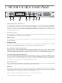
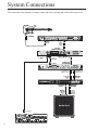
®
Instruction Manual
May be covered by one or more of the following: U.S. Patents #4538297, 4647876, 4696044, 4745309,
4881047, 4893099, 5124657, 5263091, 5268527, 5319713, 5333201, 5402498 and 5493617.
Other patents pending. Foreign patents pending.
HUSH ® is a registered trademark of GHS Corporation
1
Your HUSH® Ultra noise reduction system has been tested and complies with the following Standards and Directives as set forth by the European Union:
Council Directive(s):
89/336/EEC
Standard(s):
EN55013, EN50082-1
Electromagnetic Compatibility
This means that this product has been designed to meet stringent guidelines on how much RF
energy it can emit, and that it should be immune from other sources of interference when properly
used. Improper use of this equipment could result in increased RF emissions, which may or may
not interfere with other electronic products.
To insure against this possibility, always use good shielded cables for all audio input and output
connections. Also, bundle audio cables separately from the AC power cables. These steps will help
insure compliance with the Directive(s).
For more information about other Rocktron products, please see your local dealer or one of our
importers closest to you (listed on the enclosed warranty sheet).
Copyright © 2009 GHS Corporation
All Rights Reserved.
2
CONTENTS
1. Introduction
4
2. HUSH Ultra Front Panel
6
3. HUSH Ultra Back Panel
7
4. Quick Start
8
5. HUSH & GATE Threshold Controls
9
6. System Connections
10
7. HUSH Description
14
8. HUSH Ultra Edit Mode (Functions & Parameters)
� TITLE EDIT Function
� TRUE BYPASS Function
� HUSH® Function
� GLOBAL Function
� MIDI CTRLINK Function
� PRESET MAPPING Function
� MIDI DUMP/LOAD Function
� FUNCTION & PARAMETER, RANGE Listings
16
17
17
18
19
21
22
22
23
9. Operating the HUSH Ultra
� Display Description
� Selecting a preset
� Changing preset parameters:
� Storing changed preset parameters:
� Title Edit
� Preset Mapping
� MIDI DUMP/LOAD
� MIDI IN
� MIDI THRU/OUT
� Phantom Power
24
24
25
26
27
28
30
31
33
33
34
10. HUSH Ultra Specifications
35
3
1. Introduction
Congratulations on your purchase of the Rocktron HUSH ® Ultra.
The HUSH Ultra is the ultimate noise reducing, eliminating and exterminating
processor. The HUSH Ultra’s innovative digital stereo noise exterminator provides
two channels of the same world renowned professional noise reduction patented by
Rocktron and used for years in thousands and thousands of guitar rigs and recording
studios! The HUSH Ultra features True Bypass, an LCD display and programmable
presets with MIDI control allowing you to tailor your HUSH settings on individual
presets to suit your needs. The HUSH Ultra provides BOTH 1/4” and XLR inputs and
outputs, and is easy to setup and easy to use.
Wipe out noise, eliminate hiss, crackle and other noise problems with the very best
noise reduction circuitry available today!
4
OPERATING PRECAUTIONS
NOTE: IT IS VERY IMPORTANT THAT YOU READ THIS SECTION TO
PROVIDE YEARS OF TROUBLE FREE USE. THIS UNIT REQUIRES CAREFUL HANDLING.
All warnings on this equipment and in the operating instructions should be
adhered to and all operating instructions should be followed.
Do not use this equipment near water. Care should be taken so that objects do
not fall and liquids are not spilled into the unit through any openings.
The power cord should be unplugged from the outlet when left unused for a
long period of time.
DO NOT ATTEMPT TO SERVICE THIS EQUIPMENT. THIS EQUIPMENT
SHOULD BE SERVICED BY QUALIFIED PERSONNEL ONLY. DO NOT
MAKE ANY INTERNAL ADJUSTMENTS OR ADDITIONS TO THIS EQUIPMENT AT ANY TIME. DO NOT TAMPER WITH INTERNAL ELECTRONIC
COMPONENTS AT ANY TIME. FAILURE TO FOLLOW THESE INSTRUCTIONS MAY VOID THE WARRANTY OF THIS EQUIPMENT, AS WELL AS
CAUSING SHOCK HAZARD.
POWER REQUIREMENTS
This unit accepts power from the 9VAC/1.5A adaptor supplied with the unit.
This 9 volt RMS AC voltage is internally processed by a voltage doubler which
generates a bipolar ±15 volts to maintain the headroom and sound quality of
professional, studio quality equipment. Using an external power source such as
this minimizes excessive noise and hum problems often associated with internal
transformers, providing optimal performance for the user.
OPERATING TEMPERATURE
Do not expose this unit to excessive heat. This unit is designed to operate between 32° F and 104° F (0° C and 40° C). This unit may not function properly
under extreme temperatures.
5
2. HUSH ULTRA Front Panel
1
PRESET SELECT/FUNCTION SELECT
Use this knob to select the different presets available within the HUSH Ultra. See section titled "SELECTING A PRESET"
for more information on how to select a preset. When in "EDIT MODE" it is used to select the desired "FUNCTION"
(Title Edit, True, Bypass, HUSH, Global, MIDI CTRLINK, Preset Mapping, MIDI Dump/Load, or Global Restore)
to be altered. See section titled "CHANGING PRESET PARAMETERS" in this manual for more information on the
FUNCTION SELECT control
2
IN/OUT button & LED
This switch allows for the HUSH Ultra to be bypassed when noise reduction is not required. When lit, the LED indicates
that the HUSH Ultra is currently active in the signal path.
3
DISPLAY window
All of the HUSH Ultra's presets, functions and parameters, will be displayed in this window depending on what is being
selected or adjusted.
4
STORE/EDIT button
This button is used to STORE any changes you make to presets. It is also used to put the HUSH Ultra into "PRESET
EDIT" Mode. See PRESET EDIT mode later in this manual for more details on this function.
5
HUSH THRESHOLD/PARAMETER ADJUST
This control sets the point at which the downward expander and dynamic filter begin to operate. When in "EDIT
MODE" this control is used to ADJUST the selected PARAMETER, within the selected FUNCTION. See section titled
"CHANGING PRESET PARAMETERS" in this manual for more information on the PARAMETER ADJUST control.
6
GATE THRESHOLD/PARAMETER SELECT
This control is used to determine the level at which the gate will begin to operate. As the input signal drops below this
level, the gate will activate and downward expansion will begin. When in "EDIT MODE" this control is used to SELECT
a parameter with the selected FUNCTION to be altered. See section titled "CHANGING PRESET PARAMETERS" in
this manual for more information on the PARAMETER SELECT control.
7
GATE RELEASE LED
When lit, the Gate Release LED indicates that the input signal has dropped below the level set by the Gate Threshold
control, thus activating the gate and providing additional downward expansion.
8
REF switch
This switch determines the sensitivity of the HUSH Ultra. When using the HUSH Ultra with professional audio equipment providing a nominal output level +4dB, it is recommended that the "+4dB" setting on the unit as the Threshold
adjustment will allow you to optimize noise reduction for this reference level.
If the "-10" setting is used and the unit is overdriven, the "+4" setting should be used.
**The -10db setting is recommended for all instrument rigs.
6
3. HUSH ULTRA Rear Panel
1
CH. A (MONO) IN jacks
This XLR and ¼" mono jack provide inputs to the left channel of the HUSH Ultra. Use either the XLR
jack or the ¼" jack when connecting, but not both together. When using only one input use the "CH. A
(MONO) XLR or ¼" jack".
2
CH. B IN jacks
This XLR and ¼" mono jack provide inputs to the right channel of the HUSH Ultra. Use either the XLR
jack or the ¼" jack when connecting, but not both together.
3
CH. A jacks
This XLR and ¼" mono jack provide the output from the "CH. A (MONO)" channel of the HUSH Ultra.
4
CH. B jacks
This XLR and ¼" mono jack provide the output from the "CH. B" channel of the HUSH Ultra.
Note:
When "CH. A" is used as a single signal source, the signal will be present in both the "CH.
A" and "CH. B" outputs.
5
PHANTOM POWER jack
This 2.5mm pin jack accepts power from the 9VAC adapter supplied with a Rocktron foot controller (sold
seperately). See section called "PHANTOM POWER" for more information.
6
MIDI IN jack
Use this jack to plug in your MIDI controller. This jack is a 7 Pin MIDI Jack, however a standard 5 Pin
MIDI Cable can be used. If plugging into a Rocktron MIDI controller such as the All Access,
MIDI Mate or MIDI Xchange, we recommend using the Rocktron RMM900 7-Pin MIDI Cable
(sold separately). Pins 6 and 7 supply phantom power to the Rocktron MIDI controller when
using the RMM900.
7
MIDI THRU/OUT jack
Use this jack to plug into the first MIDI controllable device in your signal chain.
8
POWER jack
Plug the included 9VAC adapter into this jack to provide power to the unit. Please follow all
precautions as outlined in this manual and the manuals of the products that are being plugged
into the HUSH Ultra. Failure to follow these precautions may void the warranty.
7
HUSH Ultra Quick Start
The HUSH ULTRA default operation settings are:
MIDI CHANNEL = OMNI
PROGRAM CHANGES = ON
PROGRAM MAPPING = OFF
HUSH ACTIVE = IN
PROGRAMMING PRESETS:
1. Choose preset number by turning the PRESET/FUNCTION SELECT Knob or use Midi Controller.
2. Adjust Hush threshold control to eliminate noise and hiss by turning the HUSH THRESHOLD/PARAMETER
SELECT Knob
3. Adjust Gate Threshold by using the GATE THRESHOLD/PARAMETER SELECT knob
***Note: If you want desired preset to be a True Bypass preset press the Bypass button now***
4. Press and release the STORE/EDIT button to save your changes
5. The display will blink “ STORE AT PRESET “
***Note: to cancel the store mode at anytime turn the PARAMETER ADJUST KNOB***
6. Use the PRESET/FUNCTION SELECT knob and pick the destination preset where you would like to save your
changes.
7. Press and release the STORE/EDIT button.
* You must adjust the Hush Threshold or Gate Threshold in order to use the store function. When not in the EDIT
mode if you want to store the current changes to the preset the store button must be pressed within 5 seconds after
the initial change. After 5 secs the HUSH ULTRA will return to the preset name standby mode. To store the changes
simply re-adjust either the Hush Threshold or Gate Threshold and press store.
8
HUSH & GATE THRESHOLD
HUSH THRESHOLD CONTROL
The front panel HUSH Threshold control determines the minimum input level at which the HUSH filter and
downward expander will begin to operate. Setting this control too high will result in a loss of sustain, as
notes will tend to die out much faster than they should. Conversely, when set too low, the expander will close
too late (if at all) and the noise floor will remain audible
GATE THRESHOLD CONTROL
The other half of the HUSH Ultra consists of a noise gate. A noise gate completely shuts off the output signal when the input
signal level drops below a prescribed threshold level (volume). On the HUSH Ultra, this threshold is determined by the Gate
Threshold control on the front panel. This control should be set so that it doesn't cut notes off (i.e., set too high), yet doesn't
activate long after a note ends (allowing the noise floor to remain audible).
This circuit is combined with the Variable Integrated Release (V.I.R.) circuit to provide an internal variable release to the
downward expander. With the V.I.R. circuit, if the guitar signal decays slowly, the downward expander will engage slowly.
If the guitar signal stops quickly, the downward expander will engage quickly. The LED indicates when downward expansion is active.
9
System Connections
This connection is an example of a mono connection from a preamp and a multi-effects processor
10
System Connections
This connection is an example of a stereo connection from a stereo preamp and multi-effects processor
11
System Connections
This is a connection example of how you can connect the HUSH Ultra to use with a guitar amp head.
12
System Connections
This is a connection example of how you can connect the HUSH Ultra to use with a guitar amp
combo.
13
HUSH Description
When used properly, the HUSH Ultra should be completely transparent (i.e., it
should not effect the audio signal—only the noise). To maximize the performance of
the HUSH Ultra, it is necessary to understand its front panel controls and how they
work together. By understanding how these controls work, it will be easier to correctly set up the HUSH Ultra to suit any application.
The HUSH Ultra front panel provides two controls which each manipulate
both channels simultaneously. The HUSH Threshold control sets the amount of
noise reduction required for a given input signal, while the Gate Threshold control
provides additional downward expansion when increased. (The Gate Threshold control may also be used by itself, allowing the unit to be used as strictly a downward
expander.)
HUSH® Section
Rocktron's patented HUSH noise reduction is a single-ended system that combines the principles of dynamic filtering and low-level downward expansion.
Dynamic Filtering
Dynamic filtering is achieved by dynamically-controlling a low pass filter to
open and close the bandwidth of the output signal depending upon the amount of
mid and high band information present in the input signal. The filter bandwidth will
only open far enough to pass the highest frequency information in the input signal,
thus reducing the noise above it.
For example, if the highest frequency present in the input signal is 8kHz, the
filter will open to pass up to 8kHz while the noise from 8kHz to 20kHz would be
reduced. If a signal with frequency components up to 20kHz appears at the input,
the dynamic filter will open to its full extreme (40kHz).
14
This means that if a signal is present at the input which consists of primarily bass components, the dynamic filter will reduce mid or high band noise. If no
mid or high band information is present, the filter will close down to a pre-set
cut-off point of 1kHz (allowing only frequencies of 1kHz and below to pass).
However, if the input signal has high frequency components present, the dynamic
filter will open fully to pass the signal and eliminate the possibility of a loss of
high end frequency response.
Downward Expansion
The second half of the HUSH process incorporates downward expansion.
The low level expander of the HUSH system operates like an electronic volume
control. The HUSH system utilizes a voltage-controlled amplifier (VCA) circuit
which can control the gain between the input and the output from unity to 30, 40
or even 50dB of gain reduction. When the input signal is above the user preset threshold point, the VCA circuit remains at unity gain. (This means that the
output signal level is equal to the input signal level.) As the input signal level
drops below the user preset threshold point, downward expansion begins. It is at
this point that the expander acts like an electronic volume control and gradually
begins to decrease the output signal level relative to the input signal level.
As the input signal drops further below the threshold point, downward
expansion increases. A drop in the input level by 20dB would cause the output
level to drop approximately 40dB (i.e., 20dB of gain reduction). In the absence
of any input signal, the expander will reduce the gain so that the noise floor
becomes inaudible.
15
Edit Mode
Functions and Parameters Descriptions
Each HUSH Ultra preset is divided up into individual blocks called "FUNCTIONS" (such as
Global, True Bypass, HUSH, Channel Link, Title Edit, MIDI Dump/Load, and Global Restore).
Within each function of each configuration is a set of controls which allow you to manipulate various aspects of that function. These controls are called "PARAMETERS." It is the setting of each of
the parameters which determines the overall sound/action of each preset.
To access these FUNCTIONS and PARAMETERS, you must first enter into the "EDIT
MODE."
The HUSH Ultra is set up to allow you to first access each function (via the FUNCTION
SELECT knob), then the parameter list for each function (via the PARAMETER SELECT knob)
and finally the adjustable value for each parameter (via the PARAMETER ADJUST knob).
The functions available for each preset are dependent upon which effect is currently recalled.
The remainder of this section will describe each of the effect-based functions and the associated
adjustable parameters they provide.
The remaining functions are utility-based, and are described in the section titled "Operating
the HUSH Ultra".
16
TITLE EDIT Function
TITLE EDIT
The Title Edit function allows you to create a unique name for your preset. The
Parameter select knob is used to move the cursor. The Parameter adjust knob is
used to change the "character" in the title.
PARAMETER SELECT = CHARACTER POSITION
PARAMETER ADJUST = CHARACTER SELECT
IMPORTANT:
When you have completed editing the TITLE you must execute STORE before leaving the TITLE
EDIT function.
TRUE BYPASS Function
The next function displayed after turning the FUNCTION SELECT knob is the "True-Bypass"
function.
The PARAMETER SELECT knob will allow you to access these Global parameters:
TBYPASS
This TBYPASS parameter allows you to select either "ON" or "OFF". When
"ON" the True Bypass is active and the signal passes directly through the HUSH
Ultra unaffected. When "OFF" is selected the unit is active and True Bypass is
off and HUSH is active.
TRUE BYPASS uses high quality relays to perform a total bypass of the HUSH ULTRA when using the ¼ jacks.
This may be activated in the EDIT MODE or via the BYPASS button on the front panel.
True bypass state will be stored into the preset.
TRUE BYPASS:
TBYPASS
TBYPASS MCC
OFF/ ON
OFF..120
MCC assigned to TBYPASS
Note: TBYPASS MCC is programmable per preset.
17
HUSH® Function
HUSH I/O
The HUSH I/O parameter simply determines whether the HUSH® circuit is active
for the current preset. When "IN" is selected the HUSH is active. When "OUT"
is selected the HUSH is "OFF".
EXP
THRESH1
The EXP THRESHOLD (Expander Threshold) parameter determines the level at
which downward expansion begins. For example, if the EXP THRESHOLD was
set at -20(dB) and the input signal dropped below -20(dB), downward expansion
would begin.
GATE
THRESH1
The GATE THRESHOLD his control is used to determine the level at which the
gate will begin to operate. As the input signal drops below this level, the gate
will activate and downward expansion will begin.
HUSH
HUSH_ THRSH_A
GATE_ THRSH_A
* HUSH_ THRSH_B
* GATE_ THRSH_B
* HUSH_ THRSH_C
* GATE_ THRSH_C
* HUSH_ THRSH_D
* GATE_ THRSH_D
IN/OUT
1 .. 64
1 .. 64
1 .. 64
1 .. 64
1 .. 64
1 .. 64
1 .. 64
1 .. 64
* Only used when MIDI MCC LINK is active.
18
GLOBAL Function
The parameters provided in this function affect ALL presets (i.e. the settings stored for these parameters
are the same for all presets).
The PARAMETER SELECT knob will allow you to access these Global parameters:
HUSH OFFSET
MIDI RX
The HUSH OFFSET parameter allows you to globally (all presets) adjust the HUSH ® Expander Threshold. This means that if this parameter is altered from 0(dB) to +3(dB), the
Expander Threshold will be 3dB higher for all presets. This feature can be useful when
switching from a quiet guitar with passive electronics to a noisy guitar with active electronics, as the active guitar would require a higher Threshold level in all presets.
MIDI RECEIVE CHANNEL - 1.. 16 OMI The default setting is OMNI
PROGRAM CHANGES
The PROGRAM CHANGES function allows you to globally turn ON/OFF the HUSH Ultra to accept Program Changes from other devices. The default setting is ON.
PRESET MAP
The PRESET MAP function allows you to globally turn ON/OFF the PRESET MAPPING
function. The preset mapping allows the HUSH Ultra to receive a Program Change from
a MIDI Controller for one preset, but to actually recall a different preset. See PRESET
MAPPING section later in this manual for more detailed information on PRESET MAPPING.
CHNLINK
The CHNLINK “ON/OFF” determines whether the CHNLINK Function is active
or “ON” or not active or “OFF”
CC_NUM
CONTINUOUS CONTROLLER NUMBER
EXP THRESH1
EXPANDER THRESHOLD 1 parameter determines the level at which downward
expansion begins. For example, if the EXP THRESHOLD was set at -20(dB) and
the input signal dropped below -20(dB), downward expansion would begin.
GATE THRESH1
GATE THRESHOLD 1 control is used to determine the level at which the gate will
begin to operate. As the input signal drops below this level, the gate will activate
and downward expansion will begin.
EXP THRESH2
EXPANDER THRESHOLD 2 parameter determines the level at which downward
expansion begins. For example, if the EXP THRESHOLD2 was set at -20(dB) and
the input signal dropped below -20(dB), downward expansion would begin. Note
that this is only used with the MIDI MCC Link is active.
GATE THRESH2
GATE THRESHOLD 2 control is used to determine the level at which the gate will
begin to operate. As the input signal drops below this level, the gate will activate
and downward expansion will begin. Note that this is only used with the MIDI
MCC Link is active
EXP THRESH3
EXPANDER THRESHOLD 3 parameter determines the level at which downward
expansion begins. For example, if the EXP THRESHOLD3 was set at -20(dB) and
the input signal dropped below -20(dB), downward expansion would begin. Note
that this is only used with the MIDI MCC Link is active.
19
GLOBAL Function continued....
20
GATE THRESH3
GATE THRESHOLD 3 control is used to determine the level at which the gate will
begin to operate. As the input signal drops below this level, the gate will activate
and downward expansion will begin. Note that this is only used with the MIDI
MCC Link is active.
EXP THRESH4
EXPANDER THRESHOLD 4 parameter determines the level at which downward
expansion begins. For example, if the EXP THRESHOLD4 was set at -20(dB) and
the input signal dropped below -20(dB), downward expansion would begin. Note
that this is only used with the MIDI MCC Link is active.
GATE THRESH4
GATE THRESHOLD 4 control is used to determine the level at which the gate will
begin to operate. As the input signal drops below this level, the gate will activate
and downward expansion will begin. Note that this is only used with the MIDI
MCC Link is active.
MIDI CTRLINK:
For most users using individual presets will cover your needs however there are some power users
that may desire to consider the following.
If you have a 4 channel amplifier that you can use 4 controllers to change channels you can program
1preset using the MCC LINK.
CTRLINK OFF ; Determines whether function is active
CC_NUM_A OFF ..120 ;Assigns controller number
This correlates to recall HUSH_ THRSH_A and HUSH_ GATE_A when determined that the controller assigned matches and that a value greater than 63 has been detected as the channel select value.
This will function with latching and momentary switching.
CC_NUM_A will map to HUSH_ THRSH_A and HUSH_ GATE_A parameters.
CC_NUM_B will map to HUSH_ THRSH_B and HUSH_ GATE_B parameters.
CC_NUM_C will map to HUSH_ THRSH_C and HUSH_ GATE_C parameters.
CC_NUM_D will map to HUSH_ THRSH_D and HUSH_ GATE_D parameters.
TBYPASS MCC controller to be used for TRUE BYPASS
DEFAULT MCC
85
86
87
88
89
Note: It is recommended that PROGRAM CHANGES in the GLOBAL FUNCTION is set to off
when using the MCC LINK mode. MCC LINK is programmable per preset if a combination of program changes and the MCC LINK is desired. When the CTRLINK is on and you are out of the EDIT
MODE and you have sent any of the mapped controllers to the Hush Ultra the Hush Threshold and
Gate Threshold controls will automatically map to the appropriate selection HUSH_ THRSH_A , B,
C or D. Example: A Midi controller sends MCC 87 with a value of 127 when you adjust the Hush
Threshold you will see HUSH_ THRSH_C on the display. Thus the HUSH ULTRA knows that set C
is currently being used.
21
PRESET MAPPING Function
PRESET MAPPING
The Preset Mapping function allows you to use a MIDI Controller to recall
different presets via program changes.
MIDI RECEIVED PROGRAM CHANGE number is on the left side of the screen.
The PRESET that will be recalled is on the right side of the screen.
Note: PRESET MAP in the GLOBAL FUNCTION must be set to ON for mapping
to be active.
MIDI DUMP/LOAD Function
22
1 PR DUMP/LOAD
This function allows you to dump 1 preset from one HUSH Ultra to a second
HUSH Ultra or a MIDI sequencer device.
BULK DUMP/LOAD
This function allows you to dump "ALL" presets from one HUSH Ultra to a
second HUSH Ultra or MIDI sequencer device
Function, Parameter, Range Listing
FUNCTION .......................
PARAMETER LIST
TITLE EDIT .......................
XXXXXXXXX
TRUE BYPASS
TBYPASS
OFF, ON
HUSH
............................
.............................................
.............................................
HUSH (Hush In/Out)
EXP THRESH1 (Expander Threshold Level)
GATE THRSH1 (Gate Threshold Level)
Out, In
1 .. 64
1 .. 64
GLOBAL ........................
.............................................
.............................................
.............................................
.............................................
.............................................
.............................................
.............................................
.............................................
.............................................
.............................................
.............................................
.............................................
.............................................
.............................................
.............................................
.............................................
.............................................
HUSH OFFSET
MIDI RECV
PROGRAM CHANGES
PRESET MAP
CTRLINK
CC_NUM_A
CC_NUM_B
CC_NUM_C
CC_NUM_D
TBYPASS MCC
EXP THRSH1 (Expander Threshold Level)
GATE THRSH1 (Gate Threshold Level)
EXP THRSH2 (Expander Threshold Level)
GATE THRSH2 (Gate Threshold Level)
EXP THRSH3 (Expander Threshold Level)
GATE THRSH3 (Gate Threshold Level)
EXP THRSH4 (Expander Threshold Level)
GATE THRSH4 (Gate Threshold Level)
-10(dB) to +30(dB)
1 .. 16, OMNI
OFF/ON
OFF/ON
OFF/ON
0 TO 120
0 TO 120
0 TO 120
0 TO 120
0 TO 120
1 .. 64
1 .. 64
1 .. 64
1 .. 64
1 .. 64
1 .. 64
1 .. 64
1 .. 64
PRESET MAPPING ...........
1 MAP TO 1, 2 MAP TO 2, etc.
MIDI DUMP/LOAD...........
.............................................
1PR DUMP/LOAD
BULK DUMP/LOAD
VERSION NUMBER .........
XXXXXXXXX
(via FUNCTION SELECT) .............................
.............
(via PARAMETER SELECT)
RANGE
(via PARAMETER ADJUST)
23
Operating the HUSH Ultra
The HUSH Ultra provides 128 stored presets.
PRESET knob or via a MIDI Controller.
Any of the 128 presets can be called up at any time via the
Each preset has the following Functions available at all times:
TITLE EDIT
TRUE BYPASS
HUSH®
GLOBAL
MIDI CTRLINK
PRESET MAPPING
MIDI DUMP/LOAD
VERSION NUMBER
Display Description
The LCD display on the HUSH Ultra provides you with the information about the preset you are in:
Top line of display will show:
PRESET NUMBER - Displays the Preset Number you have selected.
PRESET TITLE - This is the "NAME" of the preset - in the example below - USER 1
PRESET NAME
PRESET NUMBER
1
24
user
1
SELECTING A PRESET:
There are two ways to select a preset on the HUSH Ultra. You can either turn the PRESET knob to the
desired preset you wish to recall. The display will show the selected preset number.
1
1
user
1
1. Turn the preset select knob to the desired preset
2
user
2
The second way to select a preset with a MIDI Controller such as the Rocktron MIDI Xchange, MIDI
Mate, All Access or All Access LTD. See section on MIDI Connection on how to connect a MIDI Pedal
to the HUSH Ultra and follow all instructions that come with your MIDI Pedal.
25
CHANGING PRESET PARAMETERS
STEP 1 - Enter EDIT MODE by pressing the STORE/EDIT button as shown above. When in EDIT
MODE the display will show you are in "EDIT MODE" on the top line.
** EDIT MODE **
STEP 2 - To access the first "FUNCTION" to be adjusted, turn the PRESET/FUNCTION SELECT
knob. The display will then show:
***
GLOBAL
***
STEP 3 - To access the first "PARAMETER" to be adjusted, turn the GATE THRESHOLD/PARAMETER SELECT knob. The display will then show:
***
GLOBAL
MIDI RX
***
OMNI
STEP 4 - To adjust the selected "PARAMETER", turn the HUSH THRESHOLD/PARAMETER ADJUST knob. The display will then show the adjusted parameter:
***
GLOBAL
MIDI RX
***
16
NOTE: If you have changed a parameter the "STORE" LED will light. The change(s) that you made
will not be stored until you have pressed the "STORE" button. Please follow instructions on the next
page for details on how to store changed parameters.
26
STORING CHANGED PRESET PARAMETERS
STORE CHANGES AT THE SAME PRESET
While viewing a function or parameter title, press the STORE button to start the store procedure. The
words "STORE AT PRESET" will now be flashing under the changed preset name as shown below. If
you would like to store the changes made at the current preset, simply press the STORE/EDIT button again and the changes will be stored. The word "STORED" will flash once and the preset will be
stored.
1
useR
1
1
STORE AT PRESET
1
useR
1
STOREd
useR
1
STORE CHANGES AT A NEW PRESET
If you like to store the changes made at a different preset number, while viewing a function or parameter
title, press the STORE button to start the store procedure. The words "STORE AT PRESET" will now
be flashing under the changed preset name. Next turn the PRESET SELECT knob to the desired preset
number and press the STORE/EDIT button. The word "STORED" will flash once and the preset will be
stored at the selected preset
1
useR
1
2 USER 1
STORE AT PRESET
2
STORE AT PRESET
useR
1
27
Title Edit
Step 1
To begin the Title Edit function, turn the FUNCTION SELECT knob clockwise until
the HUSH Ultra displays "TITLE EDIT".
** title edit
Step 2
**
Turn the PARAMETER SELECT knob clockwise to initiate the Title Edit mode.
Turning this knob will also select the character above the part of the current title to be
edited. The letter to be adjusted will have a flashing box over the character selected.
(Flashing box)
**
title edit
1
User
**
18
Character to be changed
Step 3
Use the PARAMETER ADJUST knob to select the desired character for the current
position (flashing box).
(Flashing box)
**
title edit
1h User
Character to be changed
28
18
**
Title Edit continued......:
Step 4
To edit the next character in the next position, turn the PARAMETER SELECT knob
one step clockwise. The flashing box will move to the next character to be adjusted.
(Flashing box)
**
title edit
1huUser
**
18
Character to be changed
Step 5
After all the characters have been edited as needed, press the STORE button to
save the new title to memory. The HUSH Ultra will flash "STORED" briefly.
1hush ultra
NOTE: The STORE button must be pressed to save the new title. Exiting the Title Edit function before pressing the STORE button will erase any editing that was done in Title Edit. Also,
after flashing "STORED", the HUSH Ultra will exit the title edit mode and return to the main
preset number.
29
PRESET MAPPING Function
Step 1
Use FUNCTION SELECT while in EDIT MODE to select the PRESET MAPPING function
* PRESET MAPPING*
Step 2
Turn the PARAMETER SELECT to enter the MAPPING MODE.
* PRESET MAPPING*
1 MAP TO 15
Step 3
Now the PARAMETER SELECT correlates to the MIDI RECEIVED PROGRAM CHANGE number (number on the left side of screen.)
The PARAMETER ADJUST selects the PRESET that will be recalled (Number
on the right side of the screen) when the received program change is executed.
In above example the HUSH ULTRA received a PROGRAM CHANGE from a
midi controller for preset 1. The actual preset recalled will be 15!
Note: PRESET MAP in the GLOBAL FUNCTION must be set to ON for mapping to be active.
IMPORTANT:
After you have completed all your preset mapping you must execute STORE
before leaving the PRESET MAPPING function.
30
MIDI DUMP/LOAD
Any or all of the HUSH Ultra's presets may be dumped to another HUSH Ultra a sequencer or MIDI
utility program using a PC midi interface to create a ( .syx ) file. All the information about the presets
you have created will be dumped consisting of parameter values, title characters and controller assignments. When dumping a single preset into another HUSH Ultra, the dumped preset can be loaded into
any preset location on the receiving unit.
Note: The HUSH Ultra midi data when sent by external means such as a PC MIDI utility program you
will need to configure it as stated below.
Buffer size 264 bytes
No of buffers 16 both RX and TX
100ms between buffers be used initially as a starting point.
100ms after F7 [ optional ]
If a MIDI sequencer is used to store the data record the Sysex data in real-time or adhere to the parameters given above.
Step 1
Connect a standard MIDI cable from the MIDI OUT of the transmitting HUSH Ultra
to the MIDI IN of the receiving HUSH Ultra. Consult MIDI Connection drawing for
more information.
Step 2
If you are dumping a single preset to another HUSH Ultra, the transmitting HUSH
Ultra must have that preset selected.
Step 3
Press the "STORE/EDIT" button to enter into the "EDIT MODE". Turn the FUNCTION SELECT knob to MIDI DUMP/LOAD.
MIDI DUMP/LOAD
Step 4
On the receiving HUSH Ultra use the PRESET Select control to select the preset
location where the received preset will be stored. Note that the preset currently stored
at the selected location will be lost when the new preset is received.
31
MIDI DUMP/LOAD continued.....:
Step 5
On the transmitting HUSH Ultra, press the STORE button to dump the preset. The
transmitting HUSH Ultra will display "DUMPED"
MIDI DUMP/LOAD
1 dumped
Step 6
To BULK DUMP all presets to another HUSH Ultra or upload them to a Sequencer
or Computer using a PC MIDI interface along with a MIDI Utility program, use the
PARAMETER SELECT knob, select BULK DUMP/LOAD and follow Steps 4 and 5
MIDI DUMP/LOAD
bulk dump/load
32
MIDI IN
The MIDI IN in the HUSH Ultra will allow you to select presets directly from a MIDI controller such
as the Rocktron MIDI XChange, MIDI Mate, All Access or All Access LTD. Follow the connection
steps in the CONNECTIONS section of this manual.
Please note that though the HUSH Ultra has a 7 Pin din connector any standard 5 pin MIDI cord may be
used for device connections. This 7-pin DIN connector must be connected to the MIDI OUT jack of the
transmitting MIDI device via a standard MIDI cable, or to the MIDI THRU jack of the preceding MIDI
device (if the HUSH Ultra is within a chain of MIDI devices). Pins 6 and 7 of this connector carry
phantom power to power a Rocktron MIDI foot controller (MIDI XChange, All Access and MIDI Mate)
when a 7-pin MIDI cable is used.
MIDI OUT/THRU
The MIDI OUT/THRU in the HUSH Ultra will allow you to transmit and control other MIDI capable
devices thru the HUSH Ultra. Follow the connection steps in the CONNECTIONS SECTION of this
manual. Follow the connection steps in the CONNECTIONS section of this manual.
This standard 5-pin DIN connector can be connected to the MIDI IN jack of another device via a standard MIDI cable. There are limitations to the number of devices that can be chained (or series connected) in this fashion.
Note: Inherently in MIDI there is a limit to the number of devices which can be chained together (connected in series). With more than 3 devices, a slight distortion of the MIDI signal can occur (due to
signal degradation) which can cause an error in MIDI signal transmission. Should this problem arise, a
MIDI Thru box can be used which connects directly to the MIDI device which transmits MIDI information and has multiple connectors for the multiple devices receiving MIDI. MIDI cables should not
exceed 50 feet (15 meters) in length.
33
PHANTOM POWER
This 2.5mm PIN jack offers the ability to power Rocktron MIDI foot controllers from a 7-pin MIDI
cable which connects from the Rocktron MIDI foot controller to the MIDI IN jack on the rear panel
of HUSH Ultra.
This eliminates the need to find an AC outlet near where the footpedal would be placed during a
performance, or the need to run an extension cord out to the footswitch. Instead of inserting the AC
adaptor into the “POWER” jack of the footswitch as you would normally, plug it into the “PHANTOM POWER” jack on the HUSH Ultra. This will power the Rocktron MIDI foot controller through
pins 6 and 7 of the MIDI cable connecting the two units. The Rocktron RMM900 7-pin MIDI cable
must be used in this operation and is available from your Rocktron dealer.
34
Specifications
Maximum Input Level
+15dB (+4 Ref.)
+5dB (-10dB Ref.)
Input Impedance 1/4" Jacks
470K Ohms
Output Impedance 1/4 Jacks
100 Ohms
Input Impedance XLR Jacks
10k Ohms
Output Impedance XLR Jacks
2.2k Ohms
Effective Noise Reduction
up to 72dB
Frequency Response
Dynamic Range
Noise Floor
THD + Noise
Current Consumption
Dimensions
Power
±.5dB, 10Hz - 27kHz
105dB
-100dBu
.041% @ 0dBu, 1kHz (typ)
405mA
19" x 4" x 1¾"
9vac 2000mA
Note: 0dBv = 0.775V RMS
CE Approved
35
36
37
Rocktron -A Division of GHS Corporation
2813 Wilbur Avenue
Battle Creek MI 49037
USA
Rocktron Phone: 1-(269)-968-3351
Email:
[email protected]
www.rocktron.com
2009-0004
Rev. 6/18/09
38