1
Modicon
Modbus Plus Network
BM85 Bridge Multiplexer
User’s Guide
890 USE 103 00
Rev. 1.0
Preface
$! 0 * %((1/0.0%+*/ "+1* %* 0$%/ ++' .! *+0 %* %*# ! .!/!.2!
0$! .%#$0 0+ )+ %"5 +1. ,.+ 10/ %* (%*! 3%0$ +1. ,+(%5 +" +*0%*1+1/
,.+ 10 !2!(+,)!*0 $! %*"+.)0%+* %* 0$%/ +1)!*0 %/ /1&!0 0+
$*#! 3%0$+10 *+0%! * /$+1( *+0 ! +*/0.1! / +))%0)!*0 5
$*!% !. 10+)0%+* *
$*!% !. 10+)0%+* //1)!/ *+ .!/,+*/%%(%05 "+. *5 !..+./
0$0 )5 ,,!. %* 0$%/ +1)!*0 " 5+1 $2! *5 /1##!/0%+*/ "+.
%),.+2!)!*0/ +. )!* )!*0/ +. $2! "+1* !..+./ %* 0$%/ ,1(%0%+*
,(!/! *+0%"5 1/ 5 1/%*# 0$! "+.) +* 0$! (/0 ,#! +" 0$%/ ,1(%0%+*
+ ,.0 +" 0$%/ +1)!*0 )5 ! .!,.+ 1! %* *5 "+.) +. 5 *5
)!*/ !(!0.+*% +. )!$*%( %*(1 %*# ,$+0++,5%*# 3%0$+10
!4,.!// 3.%00!* ,!.)%//%+* +" 0$! 1(%/$!. $*!% !.
10+)0%+* *
%/ .!#%/0!.! 0. !).' +" $*!% !. 10+)0%+*
* $! "+((+3%*# .! 0. !).'/ +" $*!% !. 10+)0%+* *
+ 1/
+ %+*
+ 1/ (1/
+.(* t %/ 0. !).' +" +.(* *0!.*0%+*( *
t %/ 0. !).' +" 0/0+.) !$*+(+#%!/ *
66* 666.!66.!#%/0!.! 60. !).'/66+"66%#%0(66-1%,)!*06
+.,+.0%+*
* .! .!#%/0!.! 0. !).'/ * t %/ 0. !).' +" *0!.*0%+*( 1/%*!// $%*!/ +.,+.0%+*
%.+/+"0 *
+.,+.0%+*
.! .!#%/0!.! 0. !).'/ +" %.+/+"0
+,5.%#$0 $*!% !. 10+)0%+* *
.%*0! %* 890 USE 103 00
Preface
iii
Contents
Chapter 1
Introducing the BM85 Bridge/Multiplexers . . . . . . . . . . . . . . . . . . . .
1
-% #!550'/%+'!3!-. *) * 0. '0. $! * 0. '0. !/2*-& $! *) * 0. '0. 1!-1%!2 *" * !'. 1%''! * !'. *0)/%)# !/$* . +!-/%)# *2!- *)"%#0-/%*) !/$* . -*#-(('! *-/ * !'. *)"%#0-%)# /$! -*#-(('! * !'. *"/2-! !1!'*+(!)/ **' %/ * 0. *-/ * !'. +!%"%/%*). *2!- * !'. -% #!0'/%+'!3!- * !'. "*- *2!- *"/2-! !1!'*+(!)/ **' %/ !1!'*+(!)/ !,0%-!(!)/ 0++'%! 4 0./*(!- +!%"%/%*). *2!- * !'. -% #!0'/%+'!3!- * !'. "*- *2!- *"/2-! !1!'*+(!)/ **' %/ !1!'*+(!)/ !,0%-!(!)/ 0++'%! 4 0./*(!- Chapter 2
Device Addressing and Message Routing . . . . . . . . . . . . . . . . . . . .
17
890 USE 103 00
* 0. '0. !..#! *0/%)# /$. *0/%)# /* -*#-(('! *)/-*''!-. *0/%)# /* *./ .! !/2*-& +/!-. *0/%)# /* -% #!0'/%+'!3!-. * 0. -!.. *)1!-.%*) *0/%)# 3(+'!. Contents
v
Chapter 3
Configuring the Modbus Models . . . . . . . . . . . . . . . . . . . . . . . . . . . . .
"#+." +1 0.0 +!"(/ +2"."! &* %&/ %,0". * 2".2&"3 +# 0%" +*#&$1.0&+* .+ "// "-1&."! -1&,)"*0 +*#&$1.0&+* %" '(&/0 +!1/ +.0 .)"0"./ *#+.)0&+* +1 &(( ""! +.0 4," (2" "2& " !!."// +))1*& 0&+* .)"0"./ +.0 .&+.&04 &*' &)"+10 +!") ++/0". +!1/ !!."// , +*#&$1.&*$ 0%" +!1/ +.0/ +**" 0&*$ +3". #+. 0%" +*#&$1.0&+* "00&*$ 0%" 3&0 %"/ +**" 0&*$ 0%" ".)&*( +1. +*#&$1.0&+* +))*!/ %" "#1(0 +*#&$1.0&+* +1. +*#&$1.0&+* .""*/ *0".&*$ +))*!/ *0+ +1. .""*/ .&*0&*$ 0%" +*#&$1.0&+* 2&*$ 0%" +*#&$1.0&+* +1. .""* +1. .""* 4+10 /&*$ 0%" .""* +1. *! .""*/ +1. +. .""* 4+10 /&*$ 0%" +. .""* +1. .""* +1. .""* 4+10 /&*$ 0%" .""* "00&*$ 0%" +!1/ (1/ !!."// "00&*$ 0%" +!" vi
Contents
25
890 USE 103 00
%"* 0+ "0 0%" +!" +3 0+ "0 0%" +!" +!1/ +.0 *!& 0+. +!"/ Chapter 4
Configuring the Programmable Models . . . . . . . . . . . . . . . . . . . . . .
57
890 USE 103 00
"#+." +1 0.0 +!"(/ +2"."! &* %&/ %,0". * 2".2&"3 +# 0%" +*#&$1.0&+* .+ "// "-1&."! -1&,)"*0 -1&,)"*0 #+. .&0&*$ 0%" ,,(& 0&+* .+$.) -1&,)"*0 +. +3*(+!&*$ 0%" ,,(& 0&+* .+$.) 2".2&"3 +# 0%" "2"(+,)"*0 +#03." "2"(+,)"*0 +#03." &("/ %" *#+.)0&+* &(" "/0 *! ")+*/0.0&+* +1. " &("/ 1(0&0/'&*$ &* +1. ,,(& 0&+* */0((&*$ 0%" "2"(+,)"*0 +#03." "#1(0 .)"0"./ */0((0&+* 0",/ .",.&*$ 0%" #+. +3*(+!&*$ "00&*$ 0%" +*#&$1.0&+* 3&0 %"/ "00&*$ 0%" +!1/ (1/ !!."// *!& 0+. +!"/ 1.&*$ +3*(+!&*$ +.)( +3*(+! +!"/ ..+. +!"/ "00&*$ 0%" +!" %"* 0+ "0 0%" +!" +3 0+ "0 0%" +!" Contents
vii
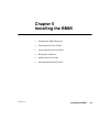
Chapter 5
Installing the BM85 . . . . . . . . . . . . . . . . . . . . . . . . . . . . . . . . . . . . . . . . .
5.1
Installing the BM85 Hardware . . . . . . . . . . . . . . . . . . . . . . . . . . . . . . . . . . . .
5.1.1
Mounting the BM85 . . . . . . . . . . . . . . . . . . . . . . . . . . . . . . . . . .
5.1.2
Shelf/Panel Mounted Models . . . . . . . . . . . . . . . . . . . . . . . . . .
5.1.3
Rack Mounted Models . . . . . . . . . . . . . . . . . . . . . . . . . . . . . . . .
Connecting the Power Cables . . . . . . . . . . . . . . . . . . . . . . . . . . . . . . . . . . . . .
5.2.1
Connecting AC Power . . . . . . . . . . . . . . . . . . . . . . . . . . . . . . . .
5.2.2
Connecting DC Power . . . . . . . . . . . . . . . . . . . . . . . . . . . . . . . .
Connecting the Network and Serial Cables . . . . . . . . . . . . . . . . . . . . . . . . .
5.3.1
Connecting a Single Network Cable . . . . . . . . . . . . . . . . . . . .
5.3.2
Connecting Dual Network Cables . . . . . . . . . . . . . . . . . . . . . .
5.3.3
Connecting DualĆCable Units on SingleĆCable Networks .
5.3.4
Connecting Serial Port Cables . . . . . . . . . . . . . . . . . . . . . . . . .
Reading the Indicators . . . . . . . . . . . . . . . . . . . . . . . . . . . . . . . . . . . . . . . . . . .
5.4.1
POWER and READY Indicators . . . . . . . . . . . . . . . . . . . . . . .
5.4.2
Modbus and Serial Port Indicators . . . . . . . . . . . . . . . . . . . . .
5.4.3
Modbus Plus Port Status Indicators . . . . . . . . . . . . . . . . . . . .
Attaching Identification Labels . . . . . . . . . . . . . . . . . . . . . . . . . . . . . . . . . . .
5.5.1
Modbus Plus Port Label . . . . . . . . . . . . . . . . . . . . . . . . . . . . . .
5.5.2
Serial Port Parameters Label . . . . . . . . . . . . . . . . . . . . . . . . . .
70
70
70
71
74
74
74
76
77
77
77
77
78
78
78
79
80
80
81
Appendix A
Compatible Devices and Cables . . . . . . . . . . . . . . . . . . . . . . . . . . . . .
83
5.2
5.3
5.4
5.5
A.1
A.2
A.3
A.4
viii
69
Contents
Compatible Devices and Cables . . . . . . . . . . . . . . . . . . . . . . . . . . . . . . . . . . .
A.1.1
Abbreviations . . . . . . . . . . . . . . . . . . . . . . . . . . . . . . . . . . . . . . .
A.1.2
Making `Quick Connections' . . . . . . . . . . . . . . . . . . . . . . . . . .
A.1.3
Devices and Cables for Configuring Modbus Ports . . . . . . .
A.1.4
Cables for Modbus Master Devices . . . . . . . . . . . . . . . . . . . . .
A.1.5
Cables for Modbus Slave Devices . . . . . . . . . . . . . . . . . . . . . .
Modbus/RS232 Cable Wiring Diagrams . . . . . . . . . . . . . . . . . . . . . . . . . . . .
Modbus/RS232 Ports Pinout . . . . . . . . . . . . . . . . . . . . . . . . . . . . . . . . . . . . . .
RS485 Ports Pinout . . . . . . . . . . . . . . . . . . . . . . . . . . . . . . . . . . . . . . . . . . . . .
84
84
84
85
85
85
86
87
88
890 USE 103 00
Glossary . . . . . . . . . . . . . . . . . . . . . . . . . . . . . . . . . . . . . . . . . . . . . . . . . . .
89
Index . . . . . . . . . . . . . . . . . . . . . . . . . . . . . . . . . . . . . . . . . . . . . . . . . . . . . .
98
Figures
890 USE 103 00
Figure 1ąBM85 Bridge/Multiplexers on Modbus Plus . . . . . . . . . . . . . . . . . . . .
Figure 2ąBM85 With Typical RS232/485 Devices . . . . . . . . . . . . . . . . . . . . . . . .
Figure 3ąBM85 With Typical Modbus Devices . . . . . . . . . . . . . . . . . . . . . . . . . . .
Figure 4ąMessage Frame Routing Path Field . . . . . . . . . . . . . . . . . . . . . . . . . . .
Figure 5ąModbus Plus Routing to Single Modbus Slave . . . . . . . . . . . . . . . . . .
3
7
11
18
19
Figure 6ąModbus Plus Routing to Networked Modbus Slave . . . . . . . . . . . . . .
Figure 7ąBridge Multiplexer Address Conversion . . . . . . . . . . . . . . . . . . . . . . . .
Figure 8ąRouting Examples . . . . . . . . . . . . . . . . . . . . . . . . . . . . . . . . . . . . . . . . . . .
Figure 9ąBM85 Modbus Port Types . . . . . . . . . . . . . . . . . . . . . . . . . . . . . . . . . . . .
Figure 10ąBM85 Modbus Models: Port Configuration Switches . . . . . . . . . . .
19
20
22
30
40
Figure 11ąTypical V1 Screen: Modbus Ports Configuration . . . . . . . . . . . . . .
Figure 12ąTypical V2 Screen: Modbus Address Map Entries . . . . . . . . . . . . .
Figure 13ąTypical V4 Screen: Save or Initialize the Configuration . . . . . . . .
Figure 14ąBM85 Modbus Models: Modbus Plus Address Switches . . . . . . . .
Figure 15ąBM85 Programmable Models: Configuration Switches . . . . . . . . .
46
48
50
52
65
Figure 16ąBM85 Programmable Models: Modbus Plus Address Switches . .
Figure 17ąMounting Dimensions: Shelf/Panel Mount Models . . . . . . . . . . . . .
Figure 18ąMounting Dimensions: Rack Mount Models . . . . . . . . . . . . . . . . . .
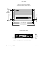
Figure 19ąBM85-000 Rear Panel . . . . . . . . . . . . . . . . . . . . . . . . . . . . . . . . . . . . .
Figure 20ąBM85C, BM85E, BM85S Rear Panel . . . . . . . . . . . . . . . . . . . . . . . . .
66
72
73
75
75
Figure 21ąBM85D Rear Panel . . . . . . . . . . . . . . . . . . . . . . . . . . . . . . . . . . . . . . . . .
Figure 22ąLayout of the Indicators . . . . . . . . . . . . . . . . . . . . . . . . . . . . . . . . . . . .
Figure 23ąModbus Plus Port Label . . . . . . . . . . . . . . . . . . . . . . . . . . . . . . . . . . . . .
Figure 24ąSerial Port Parameters Label . . . . . . . . . . . . . . . . . . . . . . . . . . . . . . . .
Figure 25ąModbus/RS232 Cable Wiring Diagrams . . . . . . . . . . . . . . . . . . . . . . .
75
78
80
81
86
Figure 26ąSerial Ports Pinout - Modbus/RS232 . . . . . . . . . . . . . . . . . . . . . . . . .
Figure 27ąSerial Ports Pinout - RS485 . . . . . . . . . . . . . . . . . . . . . . . . . . . . . . . .
87
88
Contents
ix
Chapter 1
Introducing the BM85
Bridge/Multiplexers
890 USE 103 00
V
##
" V
! V
V
V
V
V
! V
! Introducing the BM85 Bridge/Multiplexers
1
1.1 Bridge/Multiplexers on Modbus Plus
1.1.1
The Modbus Plus Network
#)' )' ' # & "(+#& '" #& ")'(& #"(&#
$$ (#"' "(+#& " ' $&#&!! #"(&# &' #'(
#!$)(&' " #(& *' (# #!!)"( (&#)#)( ( $&#)(#"
&' # " ")'(& $ "( ( ')$$#&(' )$ (# &'' "#
*' ( ( (&"'& &( # ! #" (' $& '#" " / " ) / "(+#& #")&(#"' & * '& $$ (#"' " ) (&"'&&" # $&#'' #"(&# " ')$&*'#&!''' -$ "(+#& *' " ) ##" $&#&!! #"(&# &' (( #""( (# ( "(+#& (&#) &( $#&( #" (
#"(&# & #& (&#) #!!)"(#"' #$(#" (+#& $(&'
#""( '*& (-$' # #'( #!$)(& $&#)(' (# ( "(+#&
) ($ "(+#&' " #" (&#) ##" & )' "#'
' ((' ( '" # (!/&( $$ (#"' " + "(+#& !$ #-' #" - ( *' &%)& #& ( # $&#''
1.1.2
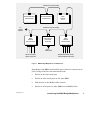
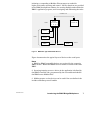
The BM85 on Modbus Plus
&..) ($ ,& #$&(' ' #)' )' "# "
$&#*' #)& '& $#&(' (( -#) " #")& '$&( - #& '&
*' " -#)& $$ (#" !# ' & * #& '" / #& ) / #)' )' "(+#&' " #& ')$$#&( # #& ##" #)' '& *'
)& '#+' # &! # (+# #)' )' "(+#&' #"
(&#) & )' & *' #!!)"( +( (
$$ (#" (&#) ( &..) ($ ,&'
2
Introducing the BM85 Bridge/Multiplexers
890 USE 103 00
MODBUS PLUS NETWORK
PROGRAMMABLE
CONTROLLER
PROGRAMMABLE
CONTROLLER
BP85
BRIDGE
PLUS
MODBUS PLUS NETWORK
TO
OTHER
NODES
BM85
BRIDGE
MULTIPLEXER
HOST DEVICE
NETWORK
ADAPTER
BM85
BRIDGE
MULTIPLEXER
HOST
COMPUTER
RS232 OR RS485
SERIAL DEVICES
MODBUS MASTER, SLAVE,
OR NETWORKED DEVICES
Figure 1 BM85 Bridge/Multiplexers on Modbus Plus
890 USE 103 00
V
V
V
V
Introducing the BM85 Bridge/Multiplexers
3
1.2 Overview of BM85 Models
1.2.1
Available Models
$&#) ( ,!## &( ''#!*!&% !% )!%#0# &( +#0#
&+) #+) %*-&(") -!* ,(!*. & )(!# '&(* &%!+(*!&%) (*(!)*!) & * $&#) (
Part Number
Mounting
Method
Operating
Power
(Nominal)
Modbus Plus
Network
Cable
Serial
Ports
Serial
Protocol
NW–BM85–000 (Note 1)
Panel or Shelf
115/230 Vac
Single
Modbus
ASCII or RTU
NW–BM85C002
Panel or Shelf
115/230 Vac or
24 Vdc
Single or Dual
Modbus
ASCII or RTU
NW–BM85D008
19 in Rack
125 Vdc or
24 Vdc
Single or Dual
Modbus
ASCII or RTU
NW–BM85E232 (Note 2)
Panel or Shelf
115/230 Vac or
24 Vdc
Single or Dual
RS232
Programmable,
User Defined
NW–BM85D002
19 in Rack
125 Vdc or
24 Vdc
Single or Dual
RS232
Programmable,
User Defined
NW–BM85E485 (Note 3)
Panel or Shelf
115/230 Vac or
24 Vdc
Single or Dual
RS485
Programmable,
User Defined
NW–BM85S232
Panel or Shelf
115/230 Vac or
24 Vdc
Single or Dual
RS232
Programmable,
User Defined
NW–BM85S485
Panel or Shelf
115/230 Vac or
24 Vdc
Single or Dual
RS485
Programmable,
User Defined
Notes
&# %- !%)*##*!&%)
) % ('# . &(
&# ) % ('# . &(
%- !%)*##*!&%)
&# ) % ('# . &(
%- !%)*##*!&%)
1.2.2
Mounting Methods
&( * '%#) # $&#) * &**&$ )+( !) !** -!* ')
&( '#$%* &% &(!/&%*# ) # ("*) ( )+''#! &( )+(!%
* +%!* *& * ) # &( &( ** !% !* *& ,(*!# '%#
"0$&+%* $&#) ( &( !%)*##*!&% !%*& )*%( 0!% ("
4
Introducing the BM85 Bridge/Multiplexers
890 USE 103 00
1.2.3
Operating Power
AC/DC Models
# , ') &, + ,.**&$ 0$-# *)0 + & )! !- ' & ("-# !)+
)* +-$)( !+)' )+ ,$("& *#, *)0 + #
& )(( -, -) ,)% - )( -# + + *( & +).($(" $, -#+)."# -#
& # )(-$(, ( &$( !., -#- $, ,,$& -) -# ., +
&& )! -# , ') &, 1 *- -# ( &,) )* +- !+)' (
1- +(& ,).+ )0 + )(( -, -) ,)% - )( -# + + *( &
+).($(" $, -#+)."# -# & # *)0 + ,).+ '.,- !., 1- +(&&2 -) -# DC/DC Models
# , ') &, )* +- !+)' )+ ,).+ )0 + )(( -,
-) - +'$(& ,-+$* )( -# + + *( & "+).($(" - +'$(& $, *+)/$ # *)0 + ,).+ '.,- !., 1- +(&&2 -) -# 1.2.4
Configuration Methods
&& ') &, '.,- )(!$".+ $(- +(&&2 !)+ 2).+ **&$-$)(
!)+ 2). ( )(( - -# ' !)+ )* +-$)( $( 2).+ **&$-$)( #$, $,
( ,,+2 ., -# , $(- +(& )(!$".+-$)( ,* $!$ , #)0 #
, +$& *)+- 0$&& )* +- # ') & #, -0) , -, )! + + *( & ,0$-# , ( , - ,,$"(, -#
)., &., () + ,, # )-# + , - &&)0, 2). -) $-# + )(!$".+
-# .($- )+ , - $- $(-) $-, ') Configuring the Modbus Port Models
)+ -# )., , +$& *)+- ') &, 2). )(!$".+ -# .($- &)&&2 - , +$& - +'$(& )(( - -) )( )! $-, *)+-,
Configuring the Programmable Port Models
)+ -# *+)"+''& ') &, 2). + - ( **&$-$)( *+)"+'
1- +(&&2 -) -# ( -# ( )0(&) $- -) -# .($- +),, -#
)., &., ( -0)+%
Setting the RUN Mode
# ( 2). #/ *+)* +&2 )'*& - 2).+ )(!$".+-$)( )! -# 2).
( , - $- $(-) $-, ') !)+ )* +-$)( $( 2).+ **&$-$)(
Caution:ąDo not connect the BM85 into your application
environment unless you have set its internal configuration.
Do not connect it to your network or to any device unless you
have set its switches properly for configuring or running.
890 USE 103 00
Introducing the BM85 Bridge/Multiplexers
5
1.3 Programmable Port Models
Operating
Power
(Nominal)
Modbus Plus
Network
Cable
Serial
Ports
Serial
Protocol
Part Number
Mounting
Method
NW–BM85E232
Panel or Shelf
115/230 Vac or
24 Vdc
Single or Dual
RS232
Programmable,
User Defined
NW–BM85D002
19 in Rack
125 Vdc or
24 Vdc
Single or Dual
RS232
Programmable,
User Defined
NW–BM85E485
Panel or Shelf
115/230 Vac or
24 Vdc
Single or Dual
RS485
Programmable,
User Defined
NW–BM85S232
Panel or Shelf
115/230 Vac or
24 Vdc
Single or Dual
RS232
Programmable,
User Defined
NW–BM85S485
Panel or Shelf
115/230 Vac or
24 Vdc
Single or Dual
RS485
Programmable,
User Defined
# !).+ , +$& *)+-, )( -# , ') &, + *+)"+''& 2 -# ., + -)
,.**)+- .,-)' )+ , +$& /$ ,
# , ') &, '.,- )0(&) 0$-# ( 1 .-& **&$-$)(
*+)"+' +),, -# )., &., ( -0)+% # )0(&) $'"
)(-$(, && )! -# $(- +(& )* +-$(" ) ., 2 -# $(&.$("
)''.($-$)( *+)-))&, !)+ -# , +$& *)+-, #(,#%$(" *+)-))&
-+(,&-$)( -0 ( *)+-, ' ,," *%"$(" .!! + ,* -
)(/ +,$)( ( ++)+ #(&$(" # , +$& *)+- $($-)+ $, $($/$.&&2
*+)"+''& -) ,#)0 -# *)+-, ,--., $( -# **&$-$)(
# $'" ( )(-$( && )! -# , +$& *)+- *+' - +, !)+ 1'*& . +- , ( *+$-2 , !$1 *+' - +, &- +(-$/ &2 -# $'"
).& *+)/$ &)& *+)-))& !.&- *+' - +, ( ' (.$("
,2,- ' !)+ -# ., + -) &)&&2 )(!$".+ -# , +$& *)+-, -#+)."# - +'$(& - )( )! -# *)+-,
( $-$)( -) ,-(+ , +$& /$ , )., ',- + )+ ,&/ /$ ,
).& --# - , +$& *)+-, $! -# ., +4 !$( ) $(&. ,
)., *+)-))& #(& +
). ( + - -# **&$-$)( *+)"+' )( ( 33 )+ )'*-$& .,$(" )$)( ,)!-0+ / &)*' (- -))&, # , +
/$&& !+)' )$)( .,-)' + +/$ ( + ,#$** , *+- &2
!+)' -# -$&, )! -# / &)*' (- -))&, + *+)/$ $(
-$)( # ( )* +- , !.&&24*+)"+'' *+) ,,)+ $( -# ., +
**&$-$)( # .($- ( &)&&2 '(" *+) ,, , - $-, , +$& *)+-,
6
Introducing the BM85 Bridge/Multiplexers
890 USE 103 00
%% # #$! % &$ &$ $$$ $ #
#-' $%%&$ #! #% %# ##* &% $ # !# '
% ' !% $ %(# # #% &%! %$$ (% %
$ !!% !# # # $$ #%#% % %$$
MODBUS PLUS
NOTE 2
BM85
BRIDGE
MULTIPLEXER
1
CONTROLLER
2 3 4
DISPLAY
NOTE 1
BARCODE
READER
MODBUS
DEVICE
SCALE
NOTE 3
Figure 2 BM85 With Typical RS232/485 Devices
&# $&#+$ % %*! * &% '$ % % $# ! #%$
Notes
# !% '$ # #"&# # % #$!%'
$ '$ % ) % $
,, &% $$ % '$ % !!% $ *
% $ %# !# # * % &$# ( %
% # $$ &$ &$
&$ $%# # $' '$ &$ % &$#- &$ &$ !# % #
890 USE 103 00
Introducing the BM85 Bridge/Multiplexers
7
1.4 Configuring the Programmable Models
Developing the Application
# -$* $#*' ) *()$"/%'$'""! "$!( -$* "*()
+!$% ) #)' %%!)$# ( ! # )# $,#!$ ) #)$
) ( #!*( ) $%')# $ $' "(( #!#
*' !!$)$# %'$)$$! $#+'($# # -$*' ('! %$') %'")'(
$* # ') ) %%!)$# %'$'" $# # .. $' $"%)!
*(# $$# ($),' +!$%"#) )$$!( )) ' (%% (%')!'$" ) ( '&*' ) *( $ $'!# .. +!$%"#)
#+'$#"#) , "*() (*%%! - ) *('
# )$# )$ )( #)'#! $#*')$# ) ( $*( !*( #$
'(( "*() ((# ( ( $# # () $ ',' (,)( $#
) '' %#!
Downloading the Application
$"%! %%!)$# # )# $,#!$ )$ ) *(# *)!)- (*%%! ,) ) $$# )$$!( $,#!$ $() # )
(" $"%*)' )) ,( *( $' +!$%# ) %%!)$# $' (%') $"%*)'
$' $,#!$# ) $() "*() $#)# $$# $*( !*(
#),$' %)' $' # $"%)! $() $' $$# %)' $' # '$ ##!$"%)! $() #),$'
$##)$# ( +!! $' ) # ) +#)- $ ) $() #$ -$*
# $,#!$ # * -$*' %%!)$# !$!!- )',( -$* #
$,#!$ ) )$ ) ) )( #()!!)$# ()
# ) *(' %%!)$# ( # ()$' # ) ) ,!! ')# - ) )' %$,' ( '"$+ ) %'")'( '
$'') $' ) #)# #()!!)$# () ) *#) # )'#(%$') )$
) () # #()!! )' ,)$*) '$#*')$#
8
Introducing the BM85 Bridge/Multiplexers
890 USE 103 00
1.4.1
Software Development Tool Kit
'$-.$)" *! !$' - -/++'$ $) .# *!.1, 0 '*+( ). &$. $+,*0$ $) .$*) # 0 '*+( ). .**'- $)'/ V
*,') 44 ,/).$( -.,./+ ,*/.$)
V
) *% . '$,,3 *! /.$'$.3 ,*/.$) - $)'/$)" !/).$*)- !*,
()"$)" (/'.$+' .-&- $) .# ++'$.$*)
V
*/- '/- . .,)-! , /.$'$.3 ,*/.$)
V
# , !$' *).$)$)" !/).$*) +,*.*.3+ -
V
*(+$' (*)-.,.$*) +,*",( 1$.# -*/, * -#*1$)"
2(+' - *! .# /- *! !/).$*)- $) .3+$' ++'$.$*)
V
-. /.$'$.$ - $)'/$)" -*/, * .#. 2 ,$- #,1,
V
# *1)'* /.$'$.3 !*, '*$)" .# ++'$.$*) .* .# # 0 '*+( ). .**' &$. $- -/++'$ *) *(+.$' $-&-
, ,$)" $)!*,(.$*) $- "$0 ) '*1
Contact
Telephone
Modicon Customer Service
1–800–468–5342 (North America)
1–508–975–5001 (International)
Part Number
Description
SR–BM85–S00
BM85 Software Development Kit (Note 1)
SR–BM85–S0R
BM85 Software Support Renewal (Note 2)
Notes
# &$. $)'/ - */( )..$*) -,$$)" #*1 .*
V
)-.'' .# 0 '*+( ). -*!.1,
V
*(+$' ) '$)& 3*/, ++'$.$*)
V
*1)'* 3*/, ++'$.$*) .* .# # &$. $)'/ - 3- *! -*!.1, 0 '*+( ). . #)$'
-/++*,. - ,0$ +,*0$ 3 *$*) /-.*( , ,0$ # -/++*,.
, ) 1' 2. )- .# -*!.1, 0 '*+( ).
. #)$' -/++*,. - ,0$ 3*) .# $)$.$' 53 + ,$*
890 USE 103 00
Introducing the BM85 Bridge/Multiplexers
9
1.5 Modbus Port Models
Part Number
Mounting
Method
Operating
Power
(Nominal)
Modbus Plus
Network
Cable
Serial
Ports
Serial
Protocol
NW–BM85–000
Panel or Shelf
115/230 Vac
Single
Modbus
ASCII or RTU
NW–BM85C002
Panel or Shelf
115/230 Vac or
24 Vdc
Single or Dual
Modbus
ASCII or RTU
NW–BM85D008
19 in Rack
125 Vdc or
24 Vdc
Single or Dual
Modbus
ASCII or RTU
#)& '& $#&(' #" (' !# ' ')$$#&( ##" #)' '&
*' ' !# ' $&#* ( #"*&'#" (+" #)'
&''' " ( &%)& &'' #&!(' #& &#)(" !''' (#
#(& #)' $#&(' #& (# #)' )' "#'
#) !)'( #")& (' !# ' # " #& #""(" (! (#
#)' )' #& (# ", *' " ,#)& $$ (#" #) " # (' ,
#""(" '& (&!" (# #" $#&( '((" '+( (# #+
# '()$ # ( $&!(&' " $$ ," $#+& (# ( '$ ,' !")' #" ( (&!" #& '((" )$ ( #")&(#"
$#&( ' '$&( , #")& #) ''" #)& "' #
$&!(&' #& $#&(
V
#&( (,$ #)' !'(& ' "( !'(& ' * #& "(+#&
V
&#(## V
#!!)"(#" $&!(&' ) &( '(#$ (' $&(, !#
V
&'' !$$" #& #"*&'#" (+" #)' &''' "
#)' )' &#)("
" (#" (# ( '& $#&( #")&(#"' ( ' #)' )'
"# &'' !)'( ''" ' ' #" " '( # &+&
'+(' #" ( && $" " ( #")&(#" ' " #!$ ( ( "(&" $&!(&'
+ &(" , ( (& $#+& ' &!#* ( $&!(&'
& #&&( ( )"( " (&"'$#&( (# ( "'( (#" '( "
"'( (& +(#)( &#")&(#"
10
Introducing the BM85 Bridge/Multiplexers
890 USE 103 00
MODBUS PLUS
BM85
BRIDGE
MULTIPLEXER
1
CONTROLLER
2 3 4
NOTE 1
MASTER
NOTE 2
SLAVE
NETWORK
MASTER
NETWORK
SLAVE
50
NETWORK
SLAVE
150
NETWORK
SLAVE
100
NETWORK
SLAVE
200
NOTE 4
NOTE 3
Figure 3 BM85 With Typical Modbus Devices
! !& % %! " ! Notes
$ ! " " " # " ! !
$ ! " " " " # " ! !
$ ! # # ! " "
% " " " ! !
$ ! # # " " " " " " ! ! " " % 890 USE 103 00
Introducing the BM85 Bridge/Multiplexers
11
1.6 Specifications (AC/DC Power Models)
1.6.1
Bridge/Multiplexer Models for AC/DC Power
Description
Mounting Method
Physical
Characteristics
Name
BM85 Modbus Plus
Bridge/Multiplexer
Part Number
NW–BM85–000, NW–BM85C002
NW–BM85E232, NW–BM85S232
NW–BM85E485, NW–BM85S485
Horizontal Surface
Platform or shelf, with included
mounting brackets
Vertical Surface
Panel, with included mounting
brackets
Height
2.59 in (66 mm)
Width
11.50 in (292 mm), unit only
14.08 in (358 mm), with mounting
brackets
Depth
8.30 in (211 mm)
Weight
5.5 lbs (2.5 kg) net
6.5 lbs (3.0 kg) shipping
AC Power
(All AC/DC Models)
DC Power
(not available on
NW–BM85–000)
Environmental
Requirements
115/230 Vac +15%. 47 ... 63 Hz
10 W
Access
Rear panel power connector with
ON/OFF switch
Fuse
1.0 A, 3 AG SB, internal
Requirements
24 Vdc +15%, 10 W
Access
Rear panel power connector
Fuse
1.0 A external, customer supplied
Temperature
0 ... 60 degrees C, operating
–40 ... +80 degrees C, storage
Network Connections
12
Humidity
0 ... 95%, non–condensing
Altitude
10,000 ft (3 km), maximum
EMI, Radiated
Susceptibility
MIL STD 461B RS03
EMI, Conducted
Susceptibility
MIL STD 461B CS03
NW–BM85–000
Single-cable network only
NW–BM85C002,
NW–BM85E232,
NW–BM85S232,
NW–BM85E485,
NW–BM85S485
Single- or dual-cable network
Introducing the BM85 Bridge/Multiplexers
890 USE 103 00
1.6.2
1.6.3
890 USE 103 00
Serial Connections
All Models
Four DB9S
Serial Parameters
NW–BM85–000,
NW–BM85C002
Modbus protocol, ASCII/RTU
300–19200 baud
odd/even/no parity
1 or 2 stop bits
NW–BM85E232,
NW–BM85S232
User defined protocol, RS232
50–19200 baud
NW–BM85E485,
NW–BM85S485
User defined protocol, RS485
50–19200 baud
Software Development Tool Kit
Contact
Telephone
Modicon Customer Service
1–800–468–5342 (North America)
1–508–975–5001 (International)
Part Number
Description
SR–BM85–S00
BM85 Software Development Kit,
3.5 in and 5.25 in HD disks,
Documentation, 90 day Technical Support
SR–BM85–S0R
BM85 Software Technical Support Renewal
Development Requirement (Supplied by Customer)
Development System
IBM PC/AT Compatible, 486 or higher recommended,
to support Development Environment
Development Environment
Borland C/C++ Compiler version 3.1 or higher,
BM85 applications use Large model
Download System
IBM PC/AT Compatible host with SA85 Adapter, or
IBM Micro Channel host with SM85 Adapter
486 or higher recommended
4 MB RAM minimum
Introducing the BM85 Bridge/Multiplexers
13
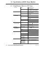
1.7 Specifications (DC/DC Power Models)
1.7.1
Bridge/Multiplexer Models for DC/DC Power
Description
Name
BM85 Modbus Plus
Bridge/Multiplexer
Part Number
NW–BM85D002, NW–BM85D008
Mounting Method
Vertical
Standard 19 in Rack
Physical
Characteristics
Height
3.47 in (88 mm)
Width
19.00 in (483 mm), mounting panel
18.26 in (464 mm), hole centers
Depth
9.15 in (232 mm)
Weight
5.5 lbs (2.5 kg) net
6.5 lbs (3.0 kg) shipping
Power
Environmental
Requirements
105 to 140 Vdc, or 24 Vdc +15%
Access
Rear panel screw terminals
Input Current
0.41 A at 125 V dc
Inrush Current
6 A typical at 125 V dc
Ground Leakage
1 mA at 140 V dc
Fuse
External, customer supplied
Temperature
0 ... 60 degrees C, operating
–40 ... +80 degrees C, storage
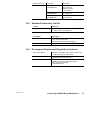
14
Humidity
0 ... 95%, non–condensing
Altitude
10,000 ft (3 km), maximum
EMI, Radiated
Susceptibility
27 ... 500 mHz, 10 V/m
IEC 801–3, level 3
IEEE/ANSI C37.90.2, 1987
Surge Withstand,
Fast Transient
± 2 kV (1 kV on I/O), V3300
generator into 50 ohms.
Corresponds to ± 4 kV (2 kV on I/O)
into open circuit.
IEC 801–4, level 3
IEEE/ANSI C37.90.1 2.3, 1989
Surge Transients
2 kV
IEC 801–5, level 3
Electrostatic Discharge
8 kV, ten discharges
IEC 801–2, level 3
Surge Withstand,
Oscillatory Wave
2.5 kV
IEEE 472
IEEE/ANSI C37.90.1 2.2, 1989
Introducing the BM85 Bridge/Multiplexers
890 USE 103 00
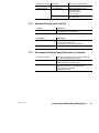
1.7.2
1.7.3
890 USE 103 00
Network Connections
All Models
Single- or dual-cable network
Serial Connections
All Models
Four DB9S
Serial Parameters
NW–BM85D008
Modbus ASCII/RTU protocol
300–19200 baud
odd/even/no parity
1 or 2 stop bits
NW–BM85D002
User defined protocol, RS232
50–19200 baud
Software Development Tool Kit
Contact
Telephone
Modicon Customer Service
1–800–468–5342 (North America)
1–508–975–5001 (International)
Part Number
Description
SR–BM85–S00
BM85 Software Development Kit,
3.5 in and 5.25 in HD disks,
Documentation, 90 day Technical Support
SR–BM85–S0R
BM85 Software Technical Support Renewal
Development Requirement (Supplied by Customer)
Development System
IBM PC/AT Compatible, 486 or higher recommended,
to support Development Environment
Development Environment
Borland C/C++ Compiler version 3.1 or higher,
BM85 applications use Large model
Download System
IBM PC/AT Compatible host with SA85 Adapter, or
IBM Micro Channel host with SM85 Adapter
486 or higher recommended
4 MB RAM minimum
Introducing the BM85 Bridge/Multiplexers
15
Chapter 2
Device Addressing
and Message Routing
890 USE 103 00
V
V
V
Device Addressing and Message Routing
17
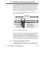
2.1 Modbus Plus Message Routing Paths
&! "(& (& !'*"% ! ) (# '" %&& !"
)& *' ) )! (!$( %&& " '*! ! ('# !'*"%& ! "! '%"( % (& )& )&
%&& "'% %"&& % (& )& , &#,! %"('!
#'& " ) ,'& *' ,' %#%&!'! ! %&& "! ' !+'
!'*"% & %"('! '" "*& !"& ! "'% !'*"%& '" %&& (# '" "(% !'*"%& *, %" ' "%!'! !"
%"('! #' & ! ' "(& (&
&!' %" ' "%!'! !"
&& % & ' &
MODBUS PLUS
MESSAGE FRAME
ROUTING
PATH
START
END
EXAMPLE:
ROUTING ADDRESS 1
ROUTING ADDRESS 2
ROUTING ADDRESS 3
ROUTING ADDRESS 4
ROUTING ADDRESS 5
ROUTING ADDRESS 1 = 25
ROUTING ADDRESS 2 = 20
ROUTING ADDRESS 3 = 12
ROUTING ADDRESSES 4, 5 = 0
(NO FURTHER ROUTING)
Figure 4 Message Frame Routing Path Field
(% & ! + # " && %"('! '" #%"%
"!'%"%
'%"( '% !'*"%& '' % "! , % (& !" )&
&& * %&' %"(' '" !" % (& "! ' "
!'*"% ' !" "%*%& ' && "! '" % (& '
%&& "! ' &"! !'*"% &"! % (& "%*%& '
&& '" '& ! &'!'"! !" %&& "! ' '% !'*"%
-%" "!'!'& " ,'& ! &#, !" (%'% && %"('!
2.1.1
Routing to Programmable Controllers
"% #%"%
"!'%"%& ' &' !"!-%" ,' ! ' &&
%"('! &#& ' !'*"% !" %&& " ' "!'%"% '" 18
Device Addressing and Message Routing
890 USE 103 00
2.1.2
Routing to Host Based Network Adapters
!$ !%& % &)!$ "&$% & +& !!) & "&$%
&)!$ ! $%% %"% &% '$ &! ) &
%% % %% '%#' & +&% $ !& + & "&$
$ ( !$ '%&! '% &! & ""&! !$ *" !$
%% !' &% !$ %&&'% !$&! 2.1.3
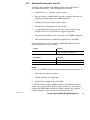
Routing to BM85 Bridge/Multiplexers
Routing to Serial Ports on BM85 Programmable Models
!$ & "$!$ !% & '%$ ""&! %&!$ & % & $%% &) !'% '% & %$ "!$&%
Routing to a Single Slave Device on BM85 Modbus Models
!$ % %( ( & !'% "!$& &)! +&% $ '% &! $%%
& ( *&&!%& ! ,$! +& $%%% & !
%& ! ,$! +& %"% & !'% "!$& &$!$ %"% & % %( (
'$ %!)% *" ! $!'& &! % %( (
BP85
ADDRESS
(1 ... 64)
BM85
ADDRESS
(1 ... 64)
BM85
PORT
(1 ... 4)
ZERO
ZERO
Figure 5 Modbus Plus Routing to Single Modbus Slave
Routing to a Networked Slave Device on BM85 Modbus Models
!$ %( ( ! !'% &)!$ & !'% "!$& &$ +&%
$ '% &! $%% & ( &$ +& $! & %& ! ,$!
+& $%%% & ! *&&!%& ! ,$!
+& %"% & !'% "!$& %& ! ,$! +& %"%
& !'% $%% ! & %( ( '$ %!)% *" ! $!'& &! &)!$ %( (
BP85
ADDRESS
(1 ... 64)
BM85
ADDRESS
(1 ... 64)
BM85
PORT
(1 ... 4)
SLAVE
ADDRESS
(1 ... 247)
ZERO
Figure 6 Modbus Plus Routing to Networked Modbus Slave
890 USE 103 00
Device Addressing and Message Routing
19
2.2 Modbus Address Conversion
Programmable Port Models
$& ( %&$&""! "$!' ( )'& %%!($# '($& # ( #' ( &''# $#*#($#' ($ )' (+# ( '&! %$&('
# $)' !)' %%!($# %&$&" ")'( # ( &$)(#
(+# '&! %$&(' ' +!! ' ( %(' ($ $)' !)' #$'
Modbus Port Models
$& ( $)' %$&( "$!' &'' $#*&'$# (+# $)' #
$)' !)' &''' ' %&$* #(&#!!- ' '& !$+
,"%!' & '$+# # ($# # ( &*' "'' ( $)' %$&( ( $)'
&'' ' $"%& ($ # #(&#! &'' "% $& (( %$&(
$) # ( "% (! )&# -$)& $#)&($# ( # $!
)% ($ $)' &''' %$#(# ($ *-( &$)(# %(
# ( (! ( * &$)(# %( -(' &
%%! ($ ( "'' ( &'( -( ' # ( &# (
"'' ' &$)( $)( $# $)' !)' ( &'( -( ' .&$ (
"'' $' ($ $)' %$&( '% # -( (+$ (( %$&(
' '#! '!* * ( &"## (& -(' & .&$' ( %$&(
' #(+$& $ '!* *' -( (& '%' ( '!* &''
255
IMPLICIT
ATTACH
ADDRESS
80
79
75
74
71
70
65
64
RESERVED
MUX ATTACH
ADDRESS
RESERVED
NOTE:
ALL ADDRESSES 65 ... 79
ARE RESERVED AT ANY
PORT CONFIGURED IN THE
‘SILENT MASTER’ MODE.
DIRECT
ATTACH
ADDRESS
1
0
RESERVED
Figure 7 Bridge Multiplexer Address Conversion
20
Device Addressing and Message Routing
890 USE 103 00
&* 0%" 0(" +*2"./&+* ,.+ ""!/ / &* &$1." # 0%" !!."// &/ &* 0%" .*$" &." 0 00 % !!."// 0%"
)"//$" &/ .+10"! 0+ 0%" /," &#& *+!" !!."// +* 0%" (+ (
+!1/ (1/ *"03+.'
# 0%" !!."// &/ &* 0%" .*$" 00 % !!."// 0%"
)"//$" &/ .+10"! 0+ /&*$(" !"2& " 0 +*" +# 0%" (+ ( +!1/ ,+.0/
!!."//"/ /,"  ,+.0/ ."/," 0&2"(5
# 0%" !!."// &/ &* 0%" .*$" ),(& &0 00 % !!."// &0 3&((
" !&2&!"! 5 3&0%&* 0%" %" -1+0&"*0 *! .")&*!". +# 0%"
!&2&/&+* 3&(( " +)" 0%" #&./0 03+ 50"/ +# 0%" #&2"50" .+10&*$ ,0%
%&/ )"0%+! ((+3/ 03+ ("2"(/ +# +!1/ (1/ !!."//&*$ 0%" -1+0&"*0
50" /," &#&"/ .&!$" (1/ !!."// +* 0%" (+ ( *"03+.' *! 0%"
.")&*!". 50" /," &#&"/ 0%" !"/0&*0&+* *+!" +* 0%" /" +*! *"03+.'
%" #&*( 0%."" 50"/ &* 0%" .+10&*$ ,0% 3&(( (35/ " 6".+/
Silent Master Port Addressing
+!1/ ,+.0 * " +*#&$1."! / &("*0 /0". *"03+.' ,+.0 *
0%&/ +*#&$1.0&+* +*" +!1/ )/0". !"2& " *! +*" +. )+." /(2"
!"2& "/ * " +**" 0"! 0+ 0%" ,+.0 %" )/0". !"2& " * !!."// &0/
+3* *"03+.'/ /(2" !"2& "/ !&." 0(5 0 * (/+ !!."// !"2& "/ 0 +0%".
,+.0/ +* 0%" /)" +. !"2& "/ .+// +!1/ (1/
," &( +*/&!".0&+*/ ." *""!"! #+. !!."//&*$ &* 0%&/ +*#&$1.0&+*
%" &*0"*0 &/ 0+ 2+&! !!."// +*#(& 0/ "03""* /(2" !!."//"/ 0 0%"
(+ ( ,+.0 *! +0%". !!."//"/ 0%0 )5 "4&/0 "(/"3%"."
%" /(2" !"2& "/ +* 0%" &("*0 /0". ,+.0 )1/0 %2" 1*&-1" !!."//"/
%"5 )1/0 *+0 " 0%" /)" / *+!" !!."// +* 0%" /
(+ ( +!1/ (1/ *"03+.' %"5 )1/0 (/+ *+0 "4&/0 / "*0.&"/ &* 0%"
!!."// ),,&*$ 0(" /0+."! 3&0%&* 0%" %" +!1/ !!."//"/
&* 0%" )/0"./ -1".&"/ 0+ 0%" /(2" !"2& "/ )1/0 *+0 ), "5+*! 0%"
&("*0 /0". ,+.0 *"&0%". 0+ *5 .+10&*$ +* +!1/ (1/ *+. 0+
*+0%". ,+.0 +* 0%" "/".2"! !!."//"/ ." 0+ " 1/"! &* 1/". ,,(& 0&+*/
%"* 0%" ,+.0 &/ +*#&$1."! / /0". ,+.0 !!."//"/ *!
." ."/".2"! !!."//"/ ." 2&((" #+. 1/"
%"* 0%" ,+.0 &/ +*#&$1."! / &("*0 /0". ,+.0 !!."//"/ ." ."/".2"!
%" .&!$" 1(0&,("4". 3&(( ."/,+*! 3&0% +!1/ "4 ",0&+* ."/,+*/"
0+ *5 )"//$" !!."//"! 0+ ."/".2"! !!."//
890 USE 103 00
Device Addressing and Message Routing
21
2.3 Routing Examples
MODBUS PLUS NETWORK (UP TO 64 NODES)
5
M
= MODEM
BM85
BRIDGE
MULTIPLEXER
1
2 3 4
8
40 (NOTE 1)
CPU A
CPU B
PRIMARY
STANDBY
M
HOT STANDBY
CONFIGURATION
MASTER
A
25
SLAVE
A
BP85
BRIDGE
PLUS
NETWORK
SLAVE
50
M
NETWORK
SLAVE
100
M
24
MODBUS PLUS NETWORK (UP TO 64 NODES)
4
BM85
BRIDGE
MULTIPLEXER
1
2 3 4
30
SA85
NETWORK
ADAPTER
TASKS: 1
2
M
MASTER
B
SLAVE
B
2
CPU C
BRIDGE
MODE
MASTER
C
NETWORK
SLAVE
150
M
NETWORK
SLAVE
200
M
NOTES:
1. STANDBY UNIT ASSUMES PRIMARY ADDRESS PLUS 32.
Figure 8 Routing Examples
22
Device Addressing and Message Routing
890 USE 103 00
% "! !$ ! # # From
To
Routing Path
CPU A (Primary)
Slave A
5
2
0
0
0
50
5
3
50
0
0
CPU C
25
2
0
0
0
SA85 (Task 1)
25
30
1
0
0
Slave B
25
4
2
0
0
200
25
4
3
200
0
SA85 (Task 2)
30
2
0
0
0
Slave B
4
2
0
0
0
200
4
3
200
0
0
CPU A (Primary)
24
8
0
0
0
CPU B (Standby)
24
40
0
0
0
100
24
5
3
100
0
Slave B
4
2
0
0
0
150
4
3
150
0
0
CPU C
2
0
0
0
0
CPU A (Primary)
24
8
0
0
0
50
24
5
3
50
0
CPU C
SA85
! " ! !& !! ! #" # " ! ! "!
From
To
Address
Routing Method
Master A
CPU A (Primary)
8
Attach
Direct
8 0 0 0 0
Slave A
72
Attach
MUX
Internal Path
CPU C
252
Attach
Implicit
252/10 = 25 2 0 0 0
50
50
Attach
Mapped
0 3 50 0 0
200
200
Attach
Mapped
25 4 3 200 0
CPU C
2
Attach
Direct
2 0 0 0 0
Slave B
72
Attach
MUX
Internal Path
CPU A (Primary)
248
Attach
Implicit
248/10 = 24 8 0 0 0
200
200
Attach
Mapped
0 3 200 0 0
50
100
Attach
Mapped
24 5 3 50 0
CPU A (Primary)
248
Attach
Implicit
248/10 = 24 8 0 0 0
CPU B (Standby)
71
Attach
Mapped
24 40 0 0 0
Slave A
72
Attach
Mapped
24 5 2 0 0
Slave B
73
Attach
Mapped
4 2 0 0 0
150
74
Attach
Mapped
4 3 150 0 0
Master B
Master C
890 USE 103 00
Device Addressing and Message Routing
23
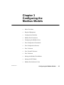
Chapter 3
Configuring the
Modbus Models
890 USE 103 00
V
" % $"$
V
!%" !% $
V
%"$ #$
V
%# "$ "$"#
V
%" $ %# "$#
V
%" %"$ #
V
%" %"$ "#
V
%" "
V
%" "#
V
%" "
V
$$ $ %# %# "##
V
$$ $ V
%# "$ $" #
Configuring the Modbus Models
25
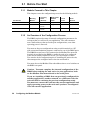
3.1 Before You Start
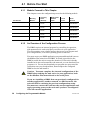
3.1.1
Models Covered in This Chapter
! " $ ! " # " !! " % !
Part Number
Mounting
Method
Operating
Power
(Nominal)
Modbus Plus
Network
Cable
Serial
Ports
Serial
Protocol
NW–BM85–000
Panel or Shelf
115/230 Vac
Single
Modbus
ASCII or RTU
NW–BM85C002
Panel or Shelf
115/230 Vac or
24 Vdc
Single or Dual
Modbus
ASCII or RTU
NW–BM85D008
19 in Rack
125 Vdc or
24 Vdc
Single or Dual
Modbus
ASCII or RTU
3.1.2
An Overview of the Configuration Process
# ! " !"# " # " " ! " "" &# % #! &# " #" "! '$" & "" !" ! " " # "! $ %
" % ! $
# #!" !" " " # "! #! ! " %" " #" " " " "!
! " $ " " " " #! #! "% !%" ! $ " " " #" " # " #" ! & !" " "! !" &# # " " # ! " # " " !" " #" " "! !"
" " ! " " # #" " " !" !" "
# #!" ! !" " #! #! !! " !" !%"! " Caution:ąYou must complete the internal configuration of the
BM85 before making the unit active in your application, both
on the Modbus Plus network and at its serial ports.
If you are installing a BM85 that was previously configured for
another application, another network, or a different node, the
unit will still be retaining its previous configuration setup.
You must not connect the unit into the current application and
apply operating power to the unit until you have reconfigured
it for the current application.
26
Configuring the Modbus Models
890 USE 103 00
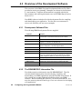
3.2 Required Equipment
) )(!$"/, .# )/- *),. *,' . ,- 3)/ 1$&& ( $.# , )! .#
!)&&)1$(" 0$ -
V
), +/$0& (. . ,'$(& 1$.# )'*.$& - ,$& &
V
), ), +/$0& (. )'*/. , *,)/. ,/(($(" . ,'$(& '/&.$)( *,)",' -/# - 1$.# )'*.$& - ,$& & &$-.$(" )! )'*.$& . ,'$(&- ( & - $- *,)0$ $( ** ($2 )' . ,'$(& '/&.$)( *,)",'- -/# - &&)1
3)/ .) -.), .# % 3-.,)% - 3)/ /- $(.) -,$*. !$& )( 3)/, $-% #$&&)1- 3)/ .) /*&$. 3)/, !/./, )(!$"/,.$)(- !,)' .# $-% 1$.#)/.
#0$(" .) % 3 $( .# *,' . ,- ! , .) .# )/' (.- !), 3)/,
'/&.$)( *,)",' !), !/,.# , .$&-
! 3)/ #0 *,$(.$(" . ,'$(& ), *,$(. , )(( . .) 3)/, '/&.),
3)/ ( *,$(. #, )*3 , ), )! 3)/, )(!$"/,.$)( #$- 1$&&
# &*!/& $( )/' (.$(" 3)/, )(!$"/,.$)( 3*$&&3 3)/ ( /3)/, . ,'$(&- ,$(. , ( ), +/$0& (. % 3 .) *,$(. .# #, )*3
890 USE 103 00
Configuring the Modbus Models
27
3.3 Configuration Checklist
$* + (% (&*# $ )$#( $' $#*'# .$*' ( )( )"( ( .$*' !()
1.
Select a terminal and cable. ' )$ %%#- $' !()# $
$"%)! )'"#! +( # !( !) )'"#! # !
)) .$* ,!! *( $' ) $#*')$#
2.
Determine the Modbus port parameters. ' )$ )$# Modbus Port Parameters. )'"# ) %'")'( .$* ,#) )$
*( $' $*( %$')
h $') .%
h !+ + '((
h $""*#)$# '")'(
h $') '$').
h # "$*)
h $" $$()'
h $*( !*( '(( !
3.
Configure the Modbus ports. *'# $ !! %$,' )$ ) ' )$ )$# Configuring the Modbus Ports.
$##) .$*' )'"#! )$ ) %$') .$* ,!! *( $' $#*')$#
)') .$*' )'"#! # #. "*!)$# %'$'" .$* ' *(#
) ) (,)( )$ !!$, ) $#*')$# # %$,' *% ) ( ) $#*')$# ('#( # .$' )$ $#*' ) *#)
28
4.
Set the Modbus Plus address. ' )$ )$# Setting the
Modbus Plus Address. ) ) '' %#! '(( (,)( )$
)( #$ '(( $# .$*' $*( !*( #),$' 5.
Set the RUN Mode. ' )$ )$# Setting the RUN Mode.
*'# $ !! %$,' )$ ) ) )( '' %#! (,) )$ )
"$ $##) ) *#) )$ ) $*( !*( #),$' # )$
) $*( +( ) )( #()!!)$# () $' '%%!.# %$,'
Configuring the Modbus Models
890 USE 103 00
3.4 Modbus Port Parameters
3.4.1
Information You Will Need
You will need the following information for each port that you will use in
your application. Parameters are explained in the sections indicated.
Port Type (see Section 3.4.2)
Modbus Master
Modbus Slave
Modbus Network
Modbus `Silent Master' Network
Slave Device Address (see Section 3.4.3)
1 ... 247
Communication Parameters (see Section 3.4.4)
Baud Rate: 50 ... 19200
Stop Bits: 1 or 2
Parity Mode: Even, Odd, or None
Communication Mode: ASCII or RTU
Note: Models NW-BM85C002 and NW-BM85D008 do not have a
Stop Bits setting. These models default to 8 data bits with 1 Stop Bit.
Port Priority (see Section 3.4.5)
1 ... 4
Link Timeout (see Section 3.4.6)
1 ... 3000 multiples of 100 milliseconds
Modem Booster (see Section 3.4.7)
Yes or No
Modbus Plus Address Table (see Section 3.4.8)
A routing table with up to 64 entries for translating Modbus addresses
to Modbus Plus network routing paths.
890 USE 103 00
Configuring the Modbus Models
29
3.4.2
Port Type
Master
" ! #
Slave
" ! ! #
Network
" ! ! #
Silent Master Network
" ! ! !
#
MODBUS PLUS
BM85
BRIDGE
MULTIPLEXER
1
984–785
CONTROLLER
2 3 4
MASTER
SLAVE
NETWORK
MASTER
NETWORK
SLAVE
NETWORK
SLAVE
NETWORK
SLAVE
NETWORK
SLAVE
Figure 9 BM85 Modbus Port Types
30
Configuring the Modbus Models
890 USE 103 00
3.4.3
Slave Device Address
If the port is to be configured as a Modbus single slave device port, a
slave device address must be assigned to the port in the range 1 ... 247
decimal.
The address is part of the configuration of a port to which a single slave
device is attached. This address is not applicable to Modbus master
devices, as they do not use a device address. It is also not applicable to
Modbus networked devices, as multiple devices can exist on the port.
3.4.4
Communication Parameters
You must set each port's parameters to communicate with the Modbus
device or devices attached to the port. Refer to the documents for your
devices to determine their parameters. Modicon Modbus devices
generally support the following parameters:
V
RTU (8-bit binary) mode, 9600 baud, 8 data bits, 1 or 2 stop bits,
even/odd/no parity
V
ASCII (character) mode, 9600 baud, 7 or 8 data bits, 1 or 2 stop
bits, even/odd/no parity.
Models NW-BM85C002 and NW-BM85D008 do not have a Stop Bits
setting. These models default to 8 data bits with 1 Stop Bit.
3.4.5
Port Priority
The Purpose of the Parameter
The BM85 services the four Modbus ports in a sequence that you can
establish during configuration by setting the Port Priority parameter.
Setting the Parameter
You set the sequence by assigning a priority to each port in the range
1 ... 4, with 1 being the highest priority. The port that is assigned
priority 1 will be the first port that is serviced on power up.
890 USE 103 00
Configuring the Modbus Models
31
3.4.6
Link Timeout
The Purpose of the Parameter
%!&% $ % )& % *!& ( !( !# $' ' %!
#$"! %! ! $$& % % !&$ $' "!#% *!&#
""%! % %!&% '& $ ) $' ' !( ##!#
! ( #%&# * % "#!# & %! %% % ! %!
% '
% %!&% '& $ %!! $!#% $!(# '$ * !% ' % %!
#$"! !#* %! %# ! $ #$&% ""# % ##!#$ % %
' % '& $ %!! ! ' $ %! #$"! *!&#
""%! ( ' %! (% & % % %!&% !&#$ !# %
' ! %! !# &$ % "!#% '& $!& $% %! % $!($% ' % % "!#% (%!&%
)$$' * '& $!& !!% % $& ! %
!!( V
$# !& %! %
V
$' ' "#!$$ %
!# )" ! %#!# $ %
V
"#!$$ % !# "!#% %# $%! $ ""#!)%* $
Setting the Parameter
!& $% "!#%$ %!&% "#%# $ '& % # %!&% '& #"#$ %$ &%"$ ! $! $
!# )" "#%# ! $"$ %!&% ! ) $
!# ! $! 32
Configuring the Modbus Models
890 USE 103 00
Timeout Examples
#.# .# /,*# #3*-)#/ $,. /#00'+% 0&# )'+( 0'*#,10 2)1# !& '/
/#" ,+ ," 1/ *#//%# 0.+/!0',+ ,$ 40#/ 0, 0&# -,.0 "#2'!#
+" 40#/ $.,* 0&# "#2'!#
890 USE 103 00
V
.*#0#./ 1" /0.0 "0 +, -.'04 /0,-
#.') !,**1+'!0',+ 0'*# 5 '0/ */!&.!0#.
*/ $,. 40#/ *,"# /#+"/ ,+# !&.!0#. -#. 40#
)2# !,+0.,))#. /!+ 0'*# */
0'*# */
,0) 0'*# 555555 */
/# )'+( 0'*#,10 2)1# ,$ */
V
.*#0#./ 1" /0.0 "0 -.'04 /0,-
#.') !,**1+'!0',+ 0'*# 5 '0/ */!&.!0#.
*/535 */ $,. 40#/ !&./ 40# $,. )2# !,+0.,))#. /!+ 0'*# */
0'*# */
,0) 0'*# 555555 */
/# )'+( 0'*#,10 2)1# ,$ */
V
.*#0#./ 1" /0.0 "0 -.'04 /0,-
#.') !,**1+'!0',+ 0'*# 5 '0/
*/!&.!0#.
/#!,+"/535 / $,. 40#/ !&./ 40# $,. )2# !,+0.,))#. /!+ 0'*# */
0'*# */
,0) 0'*# /55 /555*/555*/ /
/# )'+( 0'*#,10 2)1# ,$ */ ,. /
Configuring the Modbus Models
33
3.4.7
Modem Booster
How the Parameter Applies to the BM85
#! ##'(& $$ ' (# #)' $#&(' (( + #")& ' (+#& $#&(' #) + " (' "#&!(#" #& "- $#&(
-#) + )'" ' #)' (+#& $#&(
$&!(& #' "#( $$ - (# $#&( (( ' " #")& ' '" '(& #& * * $#&( #) " -$'' ( "#&!(#"
#+ #& "- $#&( -#) + )'" ' '" '(& #& * $#&(
The Purpose of the Parameter
#! ##'(& $&!(& (&!"' #+ ( + " #)' #!!"' (# "(+#& ' * *' ( #)' $#&(
" ( &*' #!!" (( ' &'' (# ' * *
( #)' "(+#& $#&( &'$#"' ' ,$( &#! ( ' * *
+# !(#' & * #& " " ( &'$#"' " - (
)"(#" # " ( #!!" '') - ( !'(& (+# "' #
#!!"' &
V
( (' (-$
# #!!" ( ' * * + '" &'$#"' (& (
#!$ (' ( (#" &%)'( " ( #!!" !'(&
* +(' #& ( &'$#"' " (&#& #(& #!!"' #"
( #)' "(+#& ""#( $&#'' )"( ( ' *' (#"
' " #!$ ( " (' &'$#"' &* (& (&"'(#"'
"(" #& ( $#&( !)'( &!" $"" )"( (( (!
#!.#!!"' ') ' '(&( " '& #!!"' &#! ##" $&#&!!" $" (# ' * #"(&# & #" (
#)' "(+#& " ( & (* - #" (! #& $&#''" "
( #"(&# & " ( &" # '#"' (# !")('
V
( (' (-$ #
#!!" ( ' * + '" " "#+ !"( # &$( # (
#!!" " !)'( $# (& - ( !'(& * (#
(&!" ( &%)'( (#" ' " #!$ ( #!!" "#+ !"( &' ( #)' "(+#& #&
$&#''" !''' (# #(& *' #" ( $#&( +
$# ( ' * * $&# - (# (&!" ( #!!"
(#" ' " #!$ ( ( + (" '" ( " &'$#"' (#
( #&"(" *
#! ##'(& $&!(& #+' -#) (# '$- + # ( (+#
!(#' + )' ( ( #)' $#&(
34
Configuring the Modbus Models
890 USE 103 00
Setting the Parameter
)/ ( - & . ) ), - !), .# ) ' ))-. , *,' . , . (3
- ,$& *),. # *,' . , 1$&& #0 .# !)&&)1$(" !! .
! 3)/ - & . ) !), .#$- *,' . , $()'$(" )''(- 1$.# !/(.$)(
) ), , *-- $, .&3 .) .# -&0 0$ . .# *),. ! .#
)''( $- !/(.$)( ) .# -&0 , -*)(- 1$&& , ./,( .) .#
),$"$(.), )! .# )/- )''( !. , .# -&0 #- )'*& . .#
, +/ -. .$)( ), 1# ( $. , ./,(- ( 2 *.$)( , -*)(- $($.$("
.#. $. ((). )'*& . .# .$)(
& .$(" - /- - .# - )( .3* )! , -*)(- !/(.$)( ) .)
/- ! .# )''( -* $!$ - !/(.$)( ) .# 1$&&
* ,!),' )(0 ,-$)( .) !/(.$)( ) !), - ($(" .# )''( .)
.# -&0 0$ # 1$&& .# ( /.)'.$&&3 #(& .# *)&&$(" )!
.# -&0 0$ /(.$& .# )''( .$)( $- )'*& . . 1$&& , ./,(
.# !$(& , -*)(- .) .# ),$"$(.), )! .# )''( # *)&&$(" *,) -$- #(& 3 .# .,(-*, (.&3 .) .# ),$"$(.),
Modem Booster Example
*,)",''$(" *( & )(( . .) )/- &/- ( .1),% )(.,)&& , ( -- -&0 )(.,)&& , .#. $- *,. )! )/- ( .1),%
. *),. # *( & ( , '). &3 $(. ,,)". *,)",' (
-.,. .# -&0 )(.,)&& ,
! .# ) ' ))-. , *,' . , $- - . .# ( $--/ )''(
1$.# !/(.$)( ) # )(0 ,.- .# !/(.$)( ) ( - (.# )(0 ,. )''( .) .# -&0 # .# ( #(& - *)&&$(" )!
.# -&0 , ./,($(" , -*)(- .) .# 1# ( .# -&0 0$ .$)( $- )'*& . ) .# ),$"$(.$(" 0$ .# , -*)(- ** ,- - .# )( !,)' .# -&0
!), !/(.$)( ) /,$(" .#$- .$' #)1 0 , (),'& ( .1),%
.,(-.$)(- ( )(.$(/ .1 ( ).# , 0$ - $( .# /- , **&$.$)(
( .# ).# , -&0 0$ - )( .# *),.- )/- ( .1),%
# ) ' ))-. , 1$&& ().
!/(.$)( 1$.# )(.,)&& ,- .#. , $( ') /(.$)( )
$- (). , )"($4 3 .#)- )(.,)&& ,- $( .#. ') )/ -#)/&
- & . .# ) ' ))-. , ) )*.$)( !), *),. .#. 1$&& #0
)(.,)&& ,- )(( . .) .#. *),.- )/- ( .1),%
890 USE 103 00
Configuring the Modbus Models
35
3.4.8
Modbus Address Map
# $) $( %*' $)'$" %*( '(( & )"( %'
'%*) $ ) %*( #((( ' + ) )( %*' %*( &%')( &%') ( )" )) $ %" *& )% $)' ( )) .%* (& . *' $
%$ *') %$
V
) "%) %$ $ ) )" ) , .%* ,$) )% &" ) $)'.
V
%$.) %*( '(( $ ) '$ #"
V
+.) '%*) $ &)
)" $)'. (& ( %, .%* , "" ,$) %*( '(( ' +
) ) %*( &%') )% %$+') $)% +.) '%*) $ &) )% )
() $) %$ + $ .%*' &&" ) %$ %*) $ $ # )% %*( "*( $% %$ ) "%" $),%'! %' %$ '#%) $),%'!
((( $ "(% '%*) )% + %$ $%)' &%') % ) $ %*( #(( ( %' $) '%# + ) %$ % )( %*(
&%')( ) ('( ) %*( '(( & )" %' )) &%') )%
$ #) ),$ ) #((( %*( '(( $ %*(
'(( ()%' $ ) )" ) %$( )!$ #) ( %*$ %' #) ( $%) %*$ ' (' "%, $ %$ ) %""%, $ &(
If a Match is Found
#) ( %*$ ) + .)( % #&& '%*) $ '%# ) )"
$)'. , "" &&" )% ) #(( $ ) , "" ($) %*) *( $ ))
'%*) $ ' ' + -#&"( % %, ) %*( '(( & )"
$ *( )% +"%& '%*) $ &)( %' %*( #(((
V
36
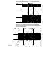
Table Location
Modbus Address
Five–Byte Routing Path
01
47
8 0 0 0 0
02
182
20 14 0 0 0
03
27
20 22 5 0 0
04
33
0 3 0 0 0
05
125
0 4 99 0 0
( $ -#&" % '%*) $ )% $% %$ ) "%"
%*( "*( $),%'! ) %*( #(( %$) $( )
() $) %$ '(( #) ( %*$ $ ) )" , "" &&". ) '%*) $ &) )% ) #(( #(( ( ) *&%$ . ) &&" ) %$ &'%'# $ ) + )
$% '(( Configuring the Modbus Models
890 USE 103 00
V
& " +!$ # %#('" '%#( % (& '# $%#%!! #"'%# % ' "# %&& #" &#" "'*#%
"" !' #% #(& %&& ' $$ & '
%#('" $' '# ' !&& ' * &"' '# "#
#" ' (%%"' #(& (& "'*#% % (& ' * %#(' '%#( ' % '# "# #" ' &#" "'*#%
V
&#*& #* ' ',$ # ) ' ' &'"'#" "
'%!" ' %#('" # !&& "" !' #% #(&
%&& ' $$ & ' %#('" $' '# '
!&& !&& & &"' '# "# #" ' (%%"' "'*#%
% (& !&& & %#(' '%#( ' % '# "#
#" ' "+' "'*#% ',$ # ) ' "# '%!"&
#* (%'% %#('" & $$ "# & "#'% % (&
' !&& & %#(' '# "# #" '% "'*#% . "# &
" #% '*#% $'% ' !&& & $' , '
$'% " $#&' '# $$ '#" '& %(""" " ' $'%
V
&#*& %#('" '# &" & ) ) #" "#'% $#%' #
' &! "" !' #% #(& %&& '
* $$ , ' %#('" $' '# ' !&& -%# " ' %&' ,' &$& "'%" %#('" '# "#'% #(&
$#%' &#" ,' &$& $#%' #%' !(&' ) #" , &" & ) ) #""' & ' %!"" ,'& % -%#&
V
&#*& %#('" '# "'*#% & ) ) #" "#'%
$#%' # ' &! ' #(& !&& #"'"& "
%&& # ' %#('" $' & $$ -%#
" ' %&' ,' &$& "'%" %#('" '# "#'% #(& $#%'
&#" ,' &$& $#%' '% ,' &$& & )
) %&& #" ' "'*#% ' '' $#%' %!""
,'& !(&' #"'" -%#&
If a Match is Not Found
" %&& !' & "#' #(" " ' ' ' #(& %&& " '
!&& * #")%' , ' "'# %#('" $' (&" '
!'#& &% #* %&( '" $' " '% '# '
#(& (& "'*#% #% '# &" & ) ) #""' '# "#'%
#(& $#%' # ' % ( '$ +%
V
' !&& #"'"& " %&& " '
%" ! ' * &"' '# ' #(& (& "# '
'' %&& #" ' # #(& (& "'*#%
#% +!$ ' !&& #"'"& #(& %&& ' * &"' '# ' #(& (& ) ' "# 890 USE 103 00
Configuring the Modbus Models
37
V
# - , -- - , , - ,0 ( '/-.
(). /- V
! .# ' --" )(.$(- ( , -- $(
.# ,(" $. 1$&& , -- .) -$("& )/- -&0
0$ . )( )! .# )/- *),.- , -- - -* $!3 *),.- , -* .$0 &3
), 2'*& $! .# ' --" )(.$(- , -- $. 1$&& ,)/. .) .# 0$ . *),. # )! .# , -- - -* $!$ - )(&3 -$("& *),. (
((). /- .) , -- )/- ( .1),% )! 0$ - . *),.
) , -- 0$ )( )/- ( .1),% .# )/- , -* .& '/-. /- V
# - , -- - , , - ,0 ( '/-.
(). /- V
! .# ' --" )(.$(- ( , -- $(
.# ,(" $. 1$&& )(0 ,. .) ,)/.$(" *.# !)&&)1-
$,-. .# , -- 1$&& $0$ 3 # +/).$ (. (
, '$( , )! .# $0$-$)( 1$&& )' .# !$,-. .1) 3. - )! .# !$0
3. ,)/.$(" *.# # , '$($(" .#, 3. - )! .# ,)/.$(" *.#
1$&& &13- 4 ,)-
), 2'*& $! .# ' --" .# , -- .# , -/&.$(" ,)/.$("
*.# 1$&& # !$,-. 3. $- .# +/).$ (. )!
.# $0$-$)( .# - )( 3. $- .# , '$( , # ' --"
1$&& - (. .) () )( .# &)& )/- &/- ( .1),%
! .# ' --" , -- $- .# , -/&.$(" ,)/.$(" *.# 1$&& # ' --" 1$&& ,)/. .) )/- &/- ()
, -- )( .# &)& ( .1),% /,.# , ,)/.$(" * (- /*)(
.# .3* )! 0$ . .#. () , -- ! () $- ,$"
&/- .# ' --" 1$&& ,)/. .#,)/"# .# ,$" .) () )(
.# ( 2. ( .1),% ! () $- ( *. , .# ' --" 1$&&
*. 3 .#. 0$ ( *)-. .) $.- **&$.$)( .-% -$(" .#$- ' .#) /* .) )/- &/- () - ( , -- # 1$.# () , -- ! .# - () - , ,$" &/ 0$ - () - ( *-- ' --" - .#,)/"# .) () - )(
- )( ( .1),% 1$.# +/).$ (.- ( , '$( ,- ) ( *-- ' --" - .) () - )( .#. ( .1),%
38
Configuring the Modbus Models
890 USE 103 00
Silent Master Port Considerations
% % $%# ! #% &#% &$ $%# ' # # &$ $' '$ % $ &$
%( # % % ! #% $ ($ % $%# ' % #$$ % $'
'$ #%* $ ( $ % #$$ %# '$ % %# ! #%$ %
$ # # $$ &$ &$
% % $%# &#% % $' '$ % ! #% &$%
' &"& #$$$ * &# !!% * &$% % % $
$ #$$ % $ &$ &$ %( #
* &$% $ % )$% $ %#$ % &$ #$$ ! %
%% * & $%&! (% % &$ #$$$ % $%#$ "&#$ % % $' '$ % %
% $%# ! #% &$% % ! * % ! #% % % * # &%
!% &$ &$ # % %# ! #% % 890 USE 103 00
Configuring the Modbus Models
39
3.5 Configuring the Modbus Ports
3.5.1
Connecting Power for the Configuration
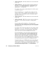
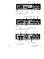
! " #! ! " ! " ! #! ! ! " ! " " " " 3.5.2
Setting the Switches
" ! " ! " " !
NW–BM85C002
NW–BM85D008
NW–BM85–000
USE
UPPER
SWITCHES
USE
RIGHT
SWITCHES
12345678
SWITCH POSITION
1 2 3 4 5 6 7 8
NW–BM85C002
NW–BM85D008 = MODE:
UP = RUN APPLICATION
(LEAVE IN UP POSITION)
PORT MODE:
CONFIGURE UP
RUN DOWN
CONFIGURATION PORT:
PORT 1
PORT 2
PORT 3
PORT 4
UP
UP
DOWN
DOWN
UP
DOWN
UP
DOWN
NW–BM85–000 = STOP BITS:
UP = 1
DOWN = 2
PARITY:
BAUD RATE:
9600 UP
2400 UP
1200 DOWN
300 DOWN
UP
DOWN
UP
DOWN
DISABLED
EVEN
DISABLED
ODD
UP
UP
DOWN
DOWN
UP
DOWN
UP
DOWN
Figure 10 BM85 Modbus Models: Port Configuration Switches
40
Configuring the Modbus Models
890 USE 103 00
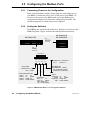
Set the CONFIGURE Mode
Set switch 1 to the CONFIGURE position (UP).
Define the Configuration Port
Switches 2 and 3 determine the port connector to be used for connecting
the serial terminal. Set them for the port you want to use.
Set the Configuration Port Parameters (NW–BM85–000)
Set switches 4 ... 8 to match the terminal's baud rate, parity mode, and
stop bits. The port always uses 8 data bits for configuration.
Set the Configuration Port Parameters (NW–BM85C002, D008)
Set switches 4 ... 7 to match the terminal's baud rate and parity mode.
The port always uses 8 data bits and 1 stop bit for configuration. Always
leave switch 8 in its RUN (UP) position. The BM85 will not run unless
switch 8 is UP.
3.5.3
Connecting the Terminal
What You Will Need
You will need a serial terminal and cable of the types listed in
, in Appendix A.
Connect the Terminal
The BM85 power should be off at this time. Connect the terminal to the
port you are using for configuration. Set the terminal's communication
parameters to match those of the BM85. Power up your terminal, and
start any emulation program you are using. Your terminal should be
running and ready, before you apply power to the BM85.
Apply Power to the BM85
When you have set the configuration switches, and your terminal is
ready, apply power to the BM85.
The configuration port's indicator should blink at one second intervals,
showing that the configuration mode is active. Your terminal should
display the MODBUS PORTS CONFIGURATION (V1) screen.
Your configuration screens and keyboard commands are described
starting at Section 3.6.
890 USE 103 00
Configuring the Modbus Models
41
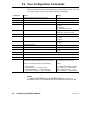
3.6 Your Configuration Commands
&! &!%!&"&! "" $ "" ! # #! " # % ! % " Command
Action
Range
V
Select a configuration screen or Help screen
1 ... 8
P
Select a port to be configured
1 ... 4
N
Enter a Modbus slave device address
1 ... 247
T
Enter the port type
M = Master
S = Slave
N = Network
X = Silent Master Network
B
Enter the baud rate
50, 300, 1200, 1800, 2000, 2400,
3600, 4800, 7200, 9600, 19200
S
Enter the stop bits
1 or 2 (Note 1)
R
Enter the parity mode
N = None
O = Odd
E = Even
M
Enter the communication mode
A = ASCII
R = RTU
Y
Enter the port priority
1 ... 4
L
Enter the link timeout value
1 ... 3000, in multiples of 100 ms
F
Enter the modem booster selection
Y = Yes
N = No
W
Write the configuration parameters to all four ports
D
Initialize all four ports with default parameters
?
Display Help for the current configuration screen
E
Enter a Modbus address and five–byte routing path into
the Modbus Address Map table on the V2 or V3 screen.
Entry format:
EYY MM XX XX XX XX XX
When you use this command, enter the following:
where:
–
–
–
–
E = Modbus Address Map command
YY = location (1 ... 64) in the table
MM = Modbus address (1 ... 255)
XX = each byte (1 ... 255) in the path.
the E command
the table location (1 ... 64) for your entry
the Modbus address (1 ... 255) to be mapped
the five bytes of routing (1 ... 255 in each byte).
Notes
! " $ " "! !"" ! ! #" " " "! %" " "
42
Configuring the Modbus Models
890 USE 103 00
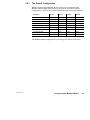
3.6.1
The Default Configuration
Parameter
Port 1
Port 2
Port 3
Port 4
Port type
Master
Slave
Slave
Slave
Slave device address
––
1
1
1
Baud rate
9600
9600
9600
9600
Stop bits
1
1
1
1
Parity mode
Even
Even
Even
Even
Communication mode
RTU
RTU
RTU
RTU
Port priority
1
2
3
4
Link timeout value
––
600
600
600
Modem booster
––
––
––
––
890 USE 103 00
Configuring the Modbus Models
43
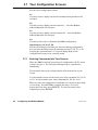
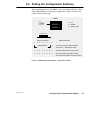
3.7 Your Configuration Screens
You have four configuration screens:
V1
Use this screen to display and set the communication parameters for
each port.
V2
Use this screen to display and set locations 1 ... 32 of the Modbus
Address Map table for each port.
V3
Use this screen to display and set locations 33 ... 64 of the Modbus
Address Map table for each port.
V4
Use this screen to Save or Initialize the BM85 configuration.
Help Screens: V5, V6, V7, V8
You have four Help screens that you can access during configuration.
You can select the Help screens by selecting screens V5, V6, V7, or V8.
Pressing the `question mark` ( ) key will display Help for the
configuration screen you are currently using.
3.7.1
Entering Commands Into Your Screens
When the BM85 is initially powered up for configuration, the V1 screen
is shown for port 1. You can begin entering the port 1 parameters
immediately.
The currently active port is always shown at the bottom line of your
screen.
To select another screen for the active port, enter commands V1, V2, V3,
or V4. To select another port, enter commands P1, P2, P3, or P4.
When you enter the configuration commands, you can enter them singly
or as a string. Press ENTER to complete the entry. To correct
keystrokes in an entry, press DELETE. To cancel an entry before
completing it, press ESCAPE.
44
Configuring the Modbus Models
890 USE 103 00
3.7.2
Printing the Configuration
&$ % !#! # # &$! #! &$ $" &$! !#
! ! $%# & # !# ! & !! &$! "!"
3.7.3
Saving the Configuration
#! $! # $" !#" "% &$! $!# $" #
"!
890 USE 103 00
Configuring the Modbus Models
45
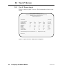
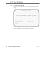
3.8 Your V1 Screen
3.8.1
Your V1 Screen Layout
MODICON MODBUS BRIDGE/MUX – Ver. 1.0
Copyright (c) 1989 MODICON, Inc., Industrial Automation Systems Group
MODBUS PORTS CONFIGURATION [V1]
Modbus Plus Address = 24
<COMMANDS>
<P>PORT NUMBER#
<T>PORT TYPE
<N>Slave Dev Addr
<B>Baud Rate
<S>Stop Bits
<R>Parity
<M>Mode
<Y>Priority
<L>Link Timeout
<F>Modem Booster
[OPTIONS]
1
master
–
9600
1
even
rtu
1
–
–
2
slave
1
1200
2
none
ascii
2
20
yes
>>Valid Commands:[V1 V2 V3 V4 P T N B S R M Y L F]
3
network
–
2400
1
even
rtu
3
10
yes
4
slave
230
9600
1
even
rtu
4
600
no
[1, 2, 3, 4]
[m, s, n, x]
[1–247]
[50–19200]
[1, 2]
[n, o, e]
[a, r]
[1–4]
[1–3000]
[y, n]
Keys:[Enter Esc ?–help]
Active Port 1>> __
Figure 11 Typical V1 Screen: Modbus Ports Configuration
46
Configuring the Modbus Models
890 USE 103 00
3.8.2
Using the V1 Screen
Select the port you want to configure. For example, enter P4 to select
Port 4 and make it the active port.
Your currently selected port is shown on the bottom line of the screen.
Specify the port type by entering T with one of the following types:
M (Master), S (Slave), N (Network), or X (Silent Master). For example,
enter TS to setup the currently active port as a slave port. A Silent
Master port will be labeled `xmaster' on the screen.
Specify the port communication parameters you want to use. For
example, enter B9600 to set the port for 9600 baud.
You can also enter the complete command sequence as a string,
separated by spaces.
Example
To configure Port 4 as a Slave port, Device Address 230, 9600 baud,
1 Stop Bit, Even Parity, RTU, Port Priority 4, 60 seconds Link Timeout,
and No Modem Booster, you would enter the following command string:
P4 TS N230 B9600 S1 RE MR Y4 L600 FN <ENTER>
890 USE 103 00
Configuring the Modbus Models
47
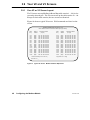
3.9 Your V2 and V3 Screens
3.9.1
Your V2 or V3 Screen Layout
" ! " MODBUS ADDRESS MAP FOR [E1–E32] [V2]
MAPS: Modbus Address to Destination Address [Port Type: Master]
Table
Entry
Modbus
Address
<E1 >
<E2 >
<E3 >
<E4 >
<E5 >
<E6 >
<E7 >
<E8 >
<E9 >
<E10>
<E11>
<E12>
<E13>
<E14>
<E15>
<E16>
[020]=
[000]=
[000]=
[124]=
[000]=
[126]=
[000]=
[000]=
[000]=
[000]=
[000]=
[000]=
[000]=
[000]=
[000]=
[000]=
Destination Address
(5 bytes)
021
000
000
020
000
020
000
000
000
000
000
000
000
000
000
000
022
000
000
004
000
006
000
000
000
000
000
000
000
000
000
000
023
000
000
000
000
000
000
000
000
000
000
000
000
000
000
000
024
000
000
000
000
000
000
000
000
000
000
000
000
000
000
000
>>Valid Commands:[V1 V2 V3 V4 P E]
025
000
000
000
000
000
000
000
000
000
000
000
000
000
000
000
Table
Entry
Modbus
Address
<E17>
<E18>
<E19>
<E20>
<E21>
<E22>
<E23>
<E24>
<E25>
<E26>
<E26>
<E28>
<E29>
<E30>
<E31>
<E32>
[000]=
[000]=
[000]=
[000]=
[000]=
[000]=
[000]=
[000]=
[000]=
[000]=
[000]=
[000]=
[000]=
[000]=
[000]=
[000]=
Destination Address
(5 bytes)
000
000
000
000
000
000
000
000
000
000
000
000
000
000
000
000
000
000
000
000
000
000
000
000
000
000
000
000
000
000
000
000
000
000
000
000
000
000
000
000
000
000
000
000
000
000
000
000
000
000
000
000
000
000
000
000
000
000
000
000
000
000
000
000
000
000
000
000
000
000
000
000
000
000
000
000
000
000
000
000
Keys:[Enter Esc ?–help]
Active Port 1>> __
Figure 12 Typical V2 Screen: Modbus Address Map Entries
48
Configuring the Modbus Models
890 USE 103 00
3.9.2
Using the V2 or V3 Screen
+ ,! +*& '* '&" -*"& &,*"+ '* ,! +$, ('*,
+ ,! +*& '* '&" -*"& &,*"+ '* ,!"+ ('*,
'- & $,*&, ,/& ,! & +*&+ -+"& '%%&+ & ! $ &,*1 '$-%& "+ $"+,"& ' $',"'&+ "& ,! ,$ ', ,!,
,!+ * ,$ &,*1 $',"'&+ &', '-+ *+++ '- %-+, &,*
,! '-+ *+++ ,!, 1'- /&, ,' %( "&,' ,! +'& '$-%&
!& 1'- ", ,! ,$ &,*"+ 1'- ' &', !. ,' ' +' "& "&
+)-& '* 0%($ 1'- ' &', !. ,' '&" -* '*
'&" -*"& &',!* &,*1
'- ' &', !. ,' "$$ $$ ,! ,$ &,*"+ "& ,! +*& '*
%#"& & &,*1 "& ,! +*& 1'- /"$$ -+ &' %'* ,!& &,*"+ 1'- %" !, "& ", '&.&"&, ,' #( ,!% $$ '& '& +*&
Example
' -+ ,! +*& ,$ &,*1 ,' %( '-+ *++ ,' ,!
*'-,"& (,! 1'- /'-$ &,* ,! '$$'/"& +,*"& '- %1 "& ", '&.&"&, ,' -+ '-+ *++"& '&.&,"'& ,!,
!$(+ 1'- ,' *%%* !'/ *+++ * %(( "& 1'-* (($","'&
'* 0%($ 1'- & -+ ,! '-+ *++ ,' "& %(("& ,' '-+ $-+ &' *++ /",! *'-,"& ,!*'- ! *" $-+ ,
*++ & ,! +% '&.&,"'& '-+ *++ /'-$ %( ,'
'-+ $-+ &' ,!*'- ! ,! +% *" 0%($+ * +!'/& "&
,$ &,*"+ & ' %( ,! *+++ +!'/& , & 1'- /'-$ &,* ,!
'$$'/"& +,*"& +
890 USE 103 00
Configuring the Modbus Models
49
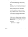
3.10 Your V4 Screen
3.10.1
Your V4 Screen Layout
SAVE AND DEFAULT CONFIGURATION [V4]
STATUS: Configuration parameters –– CHANGED –– since last save
>>Valid Commands:[V1 V2 V3 V4 W D]
Keys:[Enter Esc ?–help]
Active Port 1>> __
Figure 13 Typical V4 Screen: Save or Initialize the Configuration
50
Configuring the Modbus Models
890 USE 103 00
3.10.2
Using the V4 Screen
&!# "% # $!# '$ % #! # # #!
# & #( # #! "# $!# !#!" # #
#! $# %$" #! # & # ## #( # $!# !#!" " !" #
$" !"" #" ! $! !#" # (!"
890 USE 103 00
Configuring the Modbus Models
51
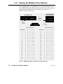
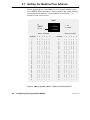
3.11 Setting the Modbus Plus Address
" ! ! ! ! ! ! NW–BM85C002
NW–BM85D008
NW–BM85–000
USE
LOWER
SWITCHES
USE
LEFT
12345678
1 = UP
SWITCHES
0 = DOWN
SWITCH POSITION
ADDRESS 1
1
2
3
4
5
6
7
8
9
10
11
12
13
14
15
16
17
18
19
20
21
22
23
24
25
26
27
28
29
30
31
32
0
1
0
1
0
1
0
1
0
1
0
1
0
1
0
1
0
1
0
1
0
1
0
1
0
1
0
1
0
1
0
1
SWITCH POSITION
2
3
4
5
6
0
0
1
1
0
0
1
1
0
0
1
1
0
0
1
1
0
0
1
1
0
0
1
1
0
0
1
1
0
0
1
1
0
0
0
0
1
1
1
1
0
0
0
0
1
1
1
1
0
0
0
0
1
1
1
1
0
0
0
0
1
1
1
1
0
0
0
0
0
0
0
0
1
1
1
1
1
1
1
1
0
0
0
0
0
0
0
0
1
1
1
1
1
1
1
1
0
0
0
0
0
0
0
0
0
0
0
0
0
0
0
0
1
1
1
1
1
1
1
1
1
1
1
1
1
1
1
1
0
0
0
0
0
0
0
0
0
0
0
0
0
0
0
0
0
0
0
0
0
0
0
0
0
0
0
0
0
0
0
0
ADDRESS
33
34
35
36
37
38
39
40
41
42
43
44
45
46
47
48
49
50
51
52
53
54
55
56
57
58
59
60
61
62
63
64
1
2
3
4
5
6
0
1
0
1
0
1
0
1
0
1
0
1
0
1
0
1
0
1
0
1
0
1
0
1
0
1
0
1
0
1
0
1
0
0
1
1
0
0
1
1
0
0
1
1
0
0
1
1
0
0
1
1
0
0
1
1
0
0
1
1
0
0
1
1
0
0
0
0
1
1
1
1
0
0
0
0
1
1
1
1
0
0
0
0
1
1
1
1
0
0
0
0
1
1
1
1
0
0
0
0
0
0
0
0
1
1
1
1
1
1
1
1
0
0
0
0
0
0
0
0
1
1
1
1
1
1
1
1
0
0
0
0
0
0
0
0
0
0
0
0
0
0
0
0
1
1
1
1
1
1
1
1
1
1
1
1
1
1
1
1
1
1
1
1
1
1
1
1
1
1
1
1
1
1
1
1
1
1
1
1
1
1
1
1
1
1
1
1
1
1
1
1
Figure 14 BM85 Modbus Models: Modbus Plus Address Switches
52
Configuring the Modbus Models
890 USE 103 00
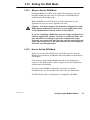
3.12 Setting the RUN Mode
3.12.1
When to Set the RUN Mode
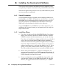
## # # #" " # !#!" ($ %
"" # $# !( ! !# # $" $"
#&! # #" $" !#"
# " #" # & #% ($!
# " " " &! " # # $#
Caution:ąYou must complete the internal configuration of the
BM85 before making the unit active in your application, both
on the Modbus Plus network and at its serial ports.
If you are installing a BM85 that was previously configured for
another application, another network, or a different node, the
unit will still be retaining its previous configuration setup.
You must not connect the unit into the current application and
apply operating power to the unit until you have reconfigured
it for the current application.
3.12.2
How to Set the RUN Mode
! ($ "# # $# # %!( ## ($ % "#$ #"
$" !# !#!" $" $" !"" " "! #" #!
$! &! # # ! $# '! "# #" $!#
"&# # # "# ! # $! ! # $!#
"&# # "##
($ % "# # $!# !!#( ! " "## "# ($ #!" !# # $# # # "# "# #
& "# & &! " !
890 USE 103 00
# # Configuring the Modbus Models
53
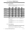
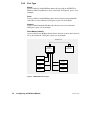
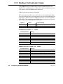
3.13 Modbus Port Indicator Codes
# # ! ! ! " ! # # ! ! ! #
Indicators
Pattern
Hexadecimal Digit
4–3–2–1
Steady
Upper digit
4–3–2–1
Flashing
Lower digit
Hardware Error Codes: 11 ... 19 Hex
Code (Hexadecimal)
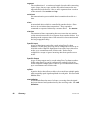
Meaning
11
PROM checksum error
12
RAM data test error
13
RAM address test error
14
Normal power down event
17
Bad or unexpected interrupt
18
EEPROM checksum error
19
Modbus port loopback error
Modbus Driver Error Codes: 24 ... 2E Hex
54
Code (Hexadecimal)
Meaning
24
Modbus transmit state error
25
Modbus receive state error
26
ASCII transmit communications state error
27
Transmit underflow error
28
RTU transmit communications state error
29
ASCII receive communications state error
2A
RTU receive communications state error
2B
Transmit communications state error
2C
Receive communications state error
Configuring the Modbus Models
890 USE 103 00
2D
Modbus state timer event error
2E
UART interrupt error
Modbus Plus Processor Interface Error Codes: 34 ... 36 Hex
Code (Hexadecimal)
Meaning
34
Modbus Plus Processor interface error
35
Modbus Plus Processor opcode response error
36
Timeout error waiting for Modbus Plus Processor
LLC Layer Error Codes: 81 ... A3 Hex
890 USE 103 00
Code (Hexadecimal)
Meaning
81
Master state error
82
Slave state error
83
Unknown routing failure to send
84 ... 8B
Port number error
91
Privilege flag not reset
92
Port number error
A2, A3
Unknown function code
Configuring the Modbus Models
55
Chapter 4
Configuring the
Programmable Models
890 USE 103 00
V
# " "
V
# #"
V
$ $% " $" "% V
!" " $" "% V
" %
V
"" " # " %"!
V
"" " #! #! !!
V
" ! # %
V
"" " Configuring the Programmable Models
57
4.1 Before You Start
4.1.1
Models Covered in This Chapter
! " Operating
Power
(Nominal)
Modbus Plus
Network
Cable
Serial
Ports
Serial
Protocol
Part Number
Mounting
Method
NW–BM85E232
Panel or Shelf
115/230 Vac or
24 Vdc
Single or Dual
RS232
Programmable,
User Defined
NW–BM85D002
19 in Rack
125 Vdc or
24 Vdc
Single or Dual
RS232
Programmable,
User Defined
NW–BM85E485
Panel or Shelf
115/230 Vac or
24 Vdc
Single or Dual
RS485
Programmable,
User Defined
NW–BM85S232
Panel or Shelf
115/230 Vac or
24 Vdc
Single or Dual
RS232
Programmable,
User Defined
NW–BM85S485
Panel or Shelf
115/230 Vac or
24 Vdc
Single or Dual
RS485
Programmable,
User Defined
4.1.2
An Overview of the Configuration Process
" # " # $! # # ! " " !
# " " " ! " #
" # " # " # "
# " Caution:ąYou must complete the internal configuration of the
BM85 before making the unit active in your application, both
on the Modbus Plus network and at its serial ports.
If you are installing a BM85 that was previously configured for
another application, another network, or different node, the
unit will still be retaining its previous configuration setup.
You must not connect the unit into the current application and
apply operating power to the unit until you have reconfigured
it for the current application.
58
Configuring the Programmable Models
890 USE 103 00
4.2 Required Equipment
4.2.1
Equipment for Writing the Application Program
First, you must create your BM85 application program. For this you will
need the BM85 Program Development Software Tool Kit. Part numbers
and ordering information are provided in the BM85 Section 1.7.2.
For compatibility with the BM85 development software, your PC
hardware should be an MS-DOS compatible platform with at least 4
Megabytes of RAM.
You will also need the Borland Cā/āC++ compiler at version 3.1 or later,
which should already be installed in your development computer. The
BM85 applications use the Large model. You should ensure that the
Borland Large model libraries are installed.
4.2.2
Equipment For Downloading the Application Program
After you create the BM85 application, you must download it to the
BM85 across Modbus Plus. Your hardware should be an IBM AT
compatible or Micro Channel PC (486 or higher recommended), with at
least 4 Megabytes of RAM. The required equipment is described in the
BM85 Section 1.7.3.
Your download host can be the same PC you used for the application
development, with the addition of a Modicon SA85 or SM85 Network
Adapter. The host could also be a separate PC node on Modbus Plus, in
which you have stored only the application and downloader software.
You might find it more convenient for developing and debugging your
application if you use the same PC for downloading. Downloading can
be performed from within the Borland development environment.
The SA85 connects an ISA (AT) bus host to Modbus Plus. The SM85
connects a Microchannel bus host. Each adapter includes a device driver
program that you will install during your installation of the adapter into
your host computer.
Your BM85 development software includes a download utility that you
can run with either the SA85 or SM85.
890 USE 103 00
Configuring the Programmable Models
59
4.3 Overview of the Development Software
( %+'+ , % ) '%'# +"%&#$) %),' %%" ) (
&'%+ )% (( () .%*' &"$$ $ -#&"( ' (%,$ %' ) %'"$
$+ '%$#$) %#&") %*#$)) %$ ( (*&&" , ) ) ! )
') $*#'( $ %'' $ $%'#) %$ ' $ ) ) %$ %*' (%),' $"*( "" % ) +"%&#$) "( %' %#& " $
$ %,$"% $ .%*' &&" ) %$ %* "(% + $ ((%')#$) %
(%*' % "( )) .%* $ *( ( -#&"(
4.3.1
Development Software Files
%""%, $ +"%&#$) "( ' (*&&" 4.3.2
File Name
Purpose
README.DOC
Complete BM85 development information text file. View or
print this file for current information about your software.
BM85LOAD.EXE
The BM85 download utility
MBPSTIM.EXE
Data transfer exerciser. Reads registers and writes a single
register to a controller over Modbus Plus.
BM85.EXE
User–compiled demonstration program to be downloaded.
See the descriptions of the test programs below.
BM85.PRJ
Borland C++ 3.1 project file to build BM85.EXE
BM85.H
Header file containing function prototypes of utility routines
C0BM85.OBJ
BM85 startup code
BM85.C
Source file for user base demonstration program. Copy the
source for a specific test program into this file and compile it.
Initially supplied as TEST0.C. See the test programs below.
BM85LIB.LIB
Library of utility routines
MBPHOST.SYS
Device driver for Modbus Plus network adapter
MBPSTAT.EXE
Modbus Plus network management and diagnostic utility
BDRESET.EXE
Initializes and enables the Modbus Plus adapter
The README.DOC Information File
%*' (!( %$) $ $ $%'#) %$ )-) " ( "
%$) $( ) " $%'#) %$ %*) +"%& $ %#& " $ $
%,$"% $ .%*' &&" ) %$ *( $ ) %'"$ $+ '%$#$) )
"(% %$) $( $. '$)". *&) $%'#) %$ %*) .%*' (%),' %' $()"" $ ) (%),' .%* (%*" + , ) ( " %*
#. "(% ,$) )% &' $)%*) ' %&. )% *( ( ''$ $ +"%& $
.%*' &&" ) %$
60
Configuring the Programmable Models
890 USE 103 00
4.3.3
Test and Demonstration Source Files
%""%- $ ") &(%, )%+( % .#&") ** /%+ $ +) $
/%+( ,"%&#$* / $ ")% #% $ +) ) *)* &(%(#)
%( .( ) $ $ *)* $ /%+( File Name
Purpose
TEST0.C
Displays a code on the BM85 LED indicators
TEST1.C
Shows Modbus Plus master and slave operation
TEST2.C
Demonstrates multitasking using the BM85 indicators
TEST3.C
Demonstrates floating point emulator
TEST4.C
Simulates process control with multitasking, C++ conventions
TEST5.C
Same as TEST4.C, but uses C conventions
TEST6.C
RS232 port loopback test
TEST7.C
RS232/RS485 port loopback test, long term
TEST8.C
Sample large program (240K) for download testing
Using the Test and Demonstration Source Files
% +) $/ " ()* %&/ * *% * "$# *$ #% / **
" %( /%+( &&" * %$ $ %#& " * %-$"% * .+*"
*% * +) $ * +* " */ %( .#&" *
%-$"% $ (+$ - * $ * %("$ $, (%$#$* +) $ *
%""%- $ )'+$
4.3.4
Key Sequence
Purpose
Alt–space
Transfer menu
m
BM85 download
Multitasking in Your Application
" ((/ $"+) +$* %$) ** /%+ $ +) *% %$)*(+* (%+* $ %( )) $ $ $ %$*(%"" $ #+"* &" *)!) %( *() - * $
/%+( &&" * %$ +"* *)! $ ) $" %$ %%&(* , ) )
$
* , *)! (%+* $ #+)* #! &( % "") *% $ ( *(* %$ (%+* $
""%- $ ** (%+* $ *% *( %$* $+ * "" $ *)! %( $"
$%*( &$ $ *)!
%+( #%$)*(* %$ &(%(#) $ &(%, )%+(
.#&") % * +) % * " ((/) #+"* *)! $ +$* %$) )
% $ ) % $ %( &(%(##() -% ( #%(
# " ( - * ** "$+
890 USE 103 00
Configuring the Programmable Models
61
4.4 Installing the Development Software
This overview of the software installation process is supplied to assist
your planning. Complete documentation is provided in the software kit.
Substitute the paths and parameters used in your Borland development
environment wherever applicable.
4.4.1
Default Parameters
The development software is supplied with two default parameters for
downloading to your BM85. One parameter specifies how to access your
SA85ā/āSM85 driver (the default specifies software interrupt vector 5C).
The other parameter is the Modbus Plus node address of the target
BM85 unit for downloading (the default is node address 4).
If your SA85ā/āSM85 driver and BM85 are set to these parameters, your
installation will be easier because you can bypass part of the setup (see
Steps 6 and 7 below).
4.4.2
Installation Steps
If you have already installed the SA85ā/āSM85 Modbus Plus adapter
and its driver, and have edited your CONFIG.SYS file to include a
DEVICE command with driver parameters, you can skip this step.
If you have not installed your adapter and driver, then you should do
so now, before proceeding with the BM85 software installation.
Follow the instructions in the guidebook supplied with your adapter.
Part of the adapter installation procedure requires you to specify a
software interrupt vector, or to accept the default vector 5C. If you
specify a vector other than the default, make a note of the vector.
You will need this information when you install the BM85 software.
62
Ensure that your Borland Cā/āC++ software is installed on your
computer and is specified in your PATH command. For example, if
the compiler's executable files are in C:ā\āBORLANDCā\āBIN then your
PATH command should specify this path.
Create a working directory for your BM85 development files, and
copy the entire contents of your BM85 development disk into this
directory. A suggested name for the new directory is: C:ā\āMBCP.
Configuring the Programmable Models
890 USE 103 00
Start your Borland compiler development environment as described
in your compiler documentation.
Update the BM85 Project file BM85.PRJ to set the correct directory
paths for your Borland environment. For example, in the Borland
3.1 environment, you can use the following key sequence:
Key Sequence
Purpose
Alt–P
Project open
BM85.PRJ
Project name
Alt–O D
Option directories
(paths)
Update the paths for your INCLUDE and LIBRARY directories
If either of these parameters is true, continue with Step 7. If
neither is true, skip Step 7 and go to Step 8.
h Your SA85/SM85 interrupt is set to a vector other than 5C
h Your BM85 Modbus Plus node address is other than 4.
890 USE 103 00
Update the BM85LOAD and MBPSTIM command lines in the BM85
project's TRANSFER menu to use the new parameters. In the
Borland 3.1 environment, you can use the following key sequence:
Key Sequence
Purpose
Alt–T
Transfer menu
Select command line
Select the BM85 DOWNLOAD or MBPLUS STIMULATE line
Alt–E
Edit
Alt–C
Command line
Enter parameters
Set the parameters as they are used in your application
Alt–M
Modify
Alt–K
OK
When you have updated your project file, close the project. In the
Borland 3.1 environment, you can use the following key sequence:
Key Sequence
Purpose
Alt–C
Project close
Configuring the Programmable Models
63
4.5 Preparing the BM85 for Downloading
!! " #& "#" "&#" "# &" # # #! # & ! !$ # ## &" !%$"'
& #! "# "&#" """ $" $" !""
! '$ & '$! # '$ $"# "# # "&#" #
& # $ $"# " "# # !"" # ! &# #
!"" !#! '$ ! $" &# # & $##' !!
"#!$#" ! "## # "&#" ! !% #" $ & # # # #" "## "# $ # #
! %# # % " ! $" $" #&! #! #
%#' '$! & "# # !! # & '
Caution:ąAdding a new node to an active network causes an
increase in the network's token rotation time, reducing the
overall data throughput. Before you connect or disconnect any
device on an active network, you should be aware of its effect
on network timing.
#! # & " # # "&#" $"# "# # &
# # !$ # # "&# "##" ! "" &!$ 64
Configuring the Programmable Models
890 USE 103 00
4.6 Setting the Configuration Switches
BM85
USE
UPPER
U = UP
SWITCHES
D = DOWN
X = DON’T CARE
12345678
SWITCH POSITION
1
2
3
4
5
6
BM85 OPERATION
7
USER DEFINED
8
U
RUN APPLICATION STORED IN BM85.
SWITCHES 1-7 DEFINED BY USER.
X
X
X
X
X
U
D
D
ALLOW DOWNLOAD OF APPLICATION.
X
X
X
X
X
D
D
D
RUN CONTINUOUS INTERNAL TESTS
SEE INDICATOR CODES IN THIS CHAPTER.
Figure 15 BM85 Programmable Models: Configuration Switches
890 USE 103 00
Configuring the Programmable Models
65
4.7 Setting the Modbus Plus Address
! BM85
USE
1 = UP
LOWER
0 = DOWN
SWITCHES
SWITCH POSITION
ADDRESS 1
1
2
3
4
5
6
7
8
9
10
11
12
13
14
15
16
17
18
19
20
21
22
23
24
25
26
27
28
29
30
31
32
0
1
0
1
0
1
0
1
0
1
0
1
0
1
0
1
0
1
0
1
0
1
0
1
0
1
0
1
0
1
0
1
SWITCH POSITION
2
3
4
5
6
0
0
1
1
0
0
1
1
0
0
1
1
0
0
1
1
0
0
1
1
0
0
1
1
0
0
1
1
0
0
1
1
0
0
0
0
1
1
1
1
0
0
0
0
1
1
1
1
0
0
0
0
1
1
1
1
0
0
0
0
1
1
1
1
0
0
0
0
0
0
0
0
1
1
1
1
1
1
1
1
0
0
0
0
0
0
0
0
1
1
1
1
1
1
1
1
0
0
0
0
0
0
0
0
0
0
0
0
0
0
0
0
1
1
1
1
1
1
1
1
1
1
1
1
1
1
1
1
0
0
0
0
0
0
0
0
0
0
0
0
0
0
0
0
0
0
0
0
0
0
0
0
0
0
0
0
0
0
0
0
ADDRESS
33
34
35
36
37
38
39
40
41
42
43
44
45
46
47
48
49
50
51
52
53
54
55
56
57
58
59
60
61
62
63
64
1
2
3
4
5
6
0
1
0
1
0
1
0
1
0
1
0
1
0
1
0
1
0
1
0
1
0
1
0
1
0
1
0
1
0
1
0
1
0
0
1
1
0
0
1
1
0
0
1
1
0
0
1
1
0
0
1
1
0
0
1
1
0
0
1
1
0
0
1
1
0
0
0
0
1
1
1
1
0
0
0
0
1
1
1
1
0
0
0
0
1
1
1
1
0
0
0
0
1
1
1
1
0
0
0
0
0
0
0
0
1
1
1
1
1
1
1
1
0
0
0
0
0
0
0
0
1
1
1
1
1
1
1
1
0
0
0
0
0
0
0
0
0
0
0
0
0
0
0
0
1
1
1
1
1
1
1
1
1
1
1
1
1
1
1
1
1
1
1
1
1
1
1
1
1
1
1
1
1
1
1
1
1
1
1
1
1
1
1
1
1
1
1
1
1
1
1
1
Figure 16 BM85 Programmable Models: Modbus Plus Address Switches
66
Configuring the Programmable Models
890 USE 103 00
4.8 Indicator Codes During Downloading
# % " "!" " # ! "! !
" " ! #! " !% !'!" !""#! !
" '#"! !% # 4.8.1
Normal Download Codes
! # % 4.8.2
Indication
Meaning
Port 4 –– Flashing two times per second
Ready for downloading
Port 3 –– ON intermittently
Receiving download from host
Port 2 –– ON (combined with port 3)
Writing to BM85 RAM
Port 1 –– ON (combined with port 3)
Erasing BM85 RAM
Error Codes
# ! # % " #! ! " &"
#" " !'! "" "! # " !
"" #! "% " ! "% & "!
!" " " ! !% !"' "" ! " "
# " "' !% ! "" ! %" "
% " "##! ! "" ! " " ""$'
" ! " !" !" " 890 USE 103 00
Indicators
Pattern
Hexadecimal Digit
4–3–2–1
Steady
Upper digit
4–3–2–1
Flashing
Lower digit
Error Code
(Hexadecimal)
Meaning
F1
BM85 kernel is reloading
F4
Program or task returned to BM85 bootstrap
F8
Program or task called abort()
FD
Could not extend heap – program called malloc() or equivalent
and had insufficient memory
FE
Could not create heap – not enough memory below code area
FF
Not enough memory to copy program to RAM area
Configuring the Programmable Models
67
4.9 Setting the RUN Mode
4.9.1
When to Set the RUN Mode
"" " " "! ! " " ! '# $
!! " #" ' " " #! #!
"% " "! #! "!
" ! "! " % "$ '#
" ! ! ! % ! " " #"
Caution:ąYou must complete the internal configuration of the
BM85 before making the unit active in your application, both
on the Modbus Plus network and at its serial ports.
If you are installing a BM85 that was previously configured for
another application, another network, or a different node, the
unit will still be retaining its previous configuration setup.
You must not connect the unit into the current application and
apply operating power to the unit until you have reconfigured
it for the current application.
4.9.2
How to Set the RUN Mode
'# !" " #" " $ ' "" '# $ !"# "!
#! " " ! #! #! !! ! ! "! " # % " " #"& !" "! # "
!%" " " !" " # " # "
!%" " !""
'# $ !" " # " "' !
!"" !" '# " ! " " #" " " !" !" "
% !" % % ! " " 68
Configuring the Programmable Models
890 USE 103 00
Chapter 5
Installing the BM85
890 USE 103 00
V
V
V
V
V
V
Installing the BM85
69
5.1 Installing the BM85 Hardware
5.1.1
Mounting the BM85
#%") ( , "" %( #%+$* $ %$ %( /%$*" )" %( ,(* "
&$" %( %( $)*""* %$ $*% )*$( $ (! $)*"" .%+( +$ *
+) $ * + " $) $ * %$ %( )" %( &$" #%+$* $ %(
%( (! #%+$* $
) )* % $ *%() *% )%- *) %&(* $ )**+) %+(
% % #%+$* $ #*% )%+" $"+ &(%&( )) %( %)(, $
*) $ *%()
%+ )%+" ")% &(%, )) *% * +$ *) (( &$" %( )** $ *
)- *) %$$* $ * ") $ )(, $
Caution:ąDo not connect the BM85 into your application
environment unless you have set its internal configuration.
Do not connect it to your network or to any device unless you
have set its switches properly for configuring or running.
* * %$) $ %( * ") %+* * %&(* $ &%-( $, (%$#$* $ %$$*%( ('+ (#$*)
5.1.2
Shelf/Panel Mounted Models
Part Number
Mounting
Method
Operating
Power
(Nominal)
Modbus Plus
Network
Cable
Serial
Ports
Serial
Protocol
NW–BM85–000
Panel or Shelf
115/230 Vac
Single
Modbus
ASCII or RTU
NW–BM85C002
Panel or Shelf
115/230 Vac or
24 Vdc
Single or Dual
Modbus
ASCII or RTU
NW–BM85E232
Panel or Shelf
115/230 Vac or
24 Vdc
Single or Dual
RS232
Programmable,
User Defined
NW–BM85E485
Panel or Shelf
115/230 Vac or
24 Vdc
Single or Dual
RS485
Programmable,
User Defined
NW–BM85S232
Panel or Shelf
115/230 Vac or
24 Vdc
Single or Dual
RS232
Programmable,
User Defined
NW–BM85S485
Panel or Shelf
115/230 Vac or
24 Vdc
Single or Dual
RS485
Programmable,
User Defined
%+$* $ #$) %$) % *) #%") ( )%-$ $ +( 70
Installing the BM85
890 USE 103 00
Horizontal Mounting
&++&$ *,) & + * $&#* !* !++ .!+ '* &) $&,%+!% &% &)!0&%+# '#+&)$ &) * # # + ,%!+ + &) #&. / #-# +& ##&.
-!.!% + !%!+&)* &,%+!% )"+* ) *,''#! .!+ + ,%!+ &)
*,)!% !+ &% + &)!0&%+# *,)
Vertical Mounting
&) -)+!# $&,%+!% ,* + )"+* *,''#! .!+ + ,%!+ &)
&#+!% +& '%# )"+* - +* + + !%*)+ !%+& *#&+* ')&-!
&% + ,%!+* &++&$ *,) & !+!&%# ).) !* )(,!) &)
*,)!% + )"+* +& + &, .!## - +& ,)%!* ).)
&) &#+!% + ,%!+ +& /&,) '%# &,) &#+* ) )(,!) /'!##/
*+%) $$ $ !% *).* &) (,!-#%+ ) *+!*+&)/
%*+## + ,%!+ + &) #&. / #-# +& ##&. -!.!% + !%!+&)*
5.1.3
Rack Mounted Models
Operating
Power
(Nominal)
Modbus Plus
Network
Cable
Serial
Ports
Serial
Protocol
Part Number
Mounting
Method
NW–BM85D008
19 in Rack
125 Vdc or
24 Vdc
Single or Dual
Modbus
ASCII or RTU
NW–BM85D002
19 in Rack
125 Vdc or
24 Vdc
Single or Dual
RS232
Programmable,
User Defined
&,%+!% !$%*!&%* & + * $&#* ) * &.% !% !,) "1$&,%+ $&#* ) *!% &) !%*+##+!&% !%+& *+%) 1!%
)" &, .!## - +& ,)%!* ).) &) &#+!% + ,%!+ +& /&,)
)" &,) &#+* ) )(,!)
% $&,%+ + ,%!+ % *,''&)+ !+*# / !+* )&%+ $&,%+!% &#+*
+ !* #! + %&, !% .! + + + /&, & %&+ - +& ')&-! )) *,''&)+
.!+ !% + )"
890 USE 103 00
Installing the BM85
71
TOP VIEW
Allow 4.0 in (102 mm) rear clearance
for access to switches, cables, and fuse
8.3 in
(211 mm)
1.53 in
(39 mm)
5.25 in
(133 mm)
11.5 in (292 mm)
12.83 in (326 mm)
14.08 in (358 mm)
REAR PANEL VIEW
2.59 in
(66 mm)
Figure 17 Mounting Dimensions: Shelf/Panel Mount Models
72
Installing the BM85
890 USE 103 00
FRONT PANEL VIEW
3.0 in
(76 mm)
3.47 in
(88 mm)
18.25 in (464 mm)
19.0 in (483 mm)
TOP VIEW
Allow 4.0 in (102 mm) rear clearance
for access to switches and cables
17.25 in (438 mm)
9.15 in
(232 mm)
8.48 in
(215 mm)
10.59 in
(269 mm)
1.44 in
(37 mm)
Figure 18 Mounting Dimensions: Rack Mount Models
890 USE 103 00
Installing the BM85
73
5.2 Connecting the Power Cables
See Sections 1.6 and 1.7 for details about the BM85
operating power and connector requirements.
Caution:ąYou can connect power cables to the BM85, but
ensure that the power is OFF before connecting the network
or serial cables to the unit.
AC/DC Models
AC/DC models are supplied with a power cable of 6 ft (2 m) length for
operation from 110-120 Vac or 220-240 Vac single-phase power. The
cable connects to a socket on the rear panel. Grounding is through the
cable. The ac line switch is located on the rear panel. The BM85
contains an ac line fuse that is accessible on the rear panel.
All of these models except the BM85-000 can also operate from an
external 24 Vdc source. Power connects to a socket on the rear panel.
Grounding is through the cable. The dc source must be switched and
fused externally to the BM85.
DC/DC Models
DC/DC models operate from a 125 Vdc or 24 Vdc source. Power connects
to a terminal strip on the rear panel. A grounding terminal is provided.
The dc source must be switched and fused externally to the BM85.
5.2.1
Connecting AC Power
Set the BM85 power switch to the `0' (power OFF) position. Connect the
BM85 to the power source. Set the power switch to `ā1ā' (power ON). The
unit's POWER indicator should illuminate.
Before connecting the network cables, set the power switch to the `0'
(power OFF) position. The unit's POWER indicator should not be lit.
5.2.2
Connecting DC Power
Set the external dc power source to OFF. Connect the BM85 to the
source. Set the dc power source to ON. The BM85 unit's POWER
indicator should illuminate.
Before proceeding with the connection of the network cables, set the dc
power source to OFF. The unit's POWER indicator should not be lit.
74
Installing the BM85
890 USE 103 00
POWER CABLE
STRAIN RELIEF
AC POWER
SELECTOR
PLUG
AND FUSE
AC POWER
SWITCH
MODBUS
PLUS
AC POWER
CONNECTOR
MODBUS PLUS
ADDRESS SWITCHES
SERIAL
PORT 2
SERIAL
PORT 4
SERIAL
PORT 1
SERIAL
PORT 3
SERIAL PORT
SWITCHES
Figure 19 BM85–000 Rear Panel
MODBUS PLUS
CHANNEL B
24V
+
SERIA
PORT 4
SERIAL
PORT 2
DC
–
AC POWER
SWITCH
AC POWER
SELECTOR
PLUG
AND FUSE
POWER CABLE
STRAIN RELIEF
MODBUS PLUS
CHANNEL A
SERIAL
PORT 1
SERIAL
PORT 3
(UPPER) SERIAL PORT SWITCHES
AC POWER
CONNECTOR
(LOWER) MODBUS PLUS ADDRESS SWITCHES
Figure 20 BM85C, BM85E, BM85S Rear Panel
GROUND
+ –
125 VDC
+ –
24 VDC
MODBUS PLUS
CHANNEL B
MODBUS PLUS
CHANNEL A
SERIAL
PORT 2
SERIAL
PORT 1
SERIAL
PORT 4
SERIAL
PORT 3
(UPPER) SERIAL PORT SWITCHES
(LOWER) MODBUS PLUS ADDRESS SWITCHES
Figure 21 BM85D Rear Panel
890 USE 103 00
Installing the BM85
75
5.3 Connecting the Network and Serial Cables
%(!# $# ! %!#$ # !% ! % ## " # " '($ # "#!' % !!( &#$
V
&# V
&# V
&# % &%! $ !( !# !
%# !
$#($
% ) %! % % $&# % !
%! ) %% %$ %(!
Caution:ąIf you are connecting the unit to the network for the
purpose of communicating in your application, you must first
ensure that you have set the unit's internal configuration for
the specific site at which you are installing the unit. If you
have not done this, you must first configure the unit as
described in this guidebook.
If you are connecting the unit to the network for the purpose
of downloading its configuration from your host computer, you
must set the unit's rear panel switches for downloading . You
must do this before connecting the network cables, and before
applying operating power to the unit.
Caution:ąIf the network is active, communication between the
devices on the network will be affected as you connect the
BM85 to the network. Before connecting any device on an
active network, you should know the affect of connecting that
device.
Caution:ąIf the cables at the installation site are not labeled,
or if you do not have a layout diagram showing how to connect
the cables, obtain that information before proceeding.
76
Installing the BM85
890 USE 103 00
5.3.1
Connecting a Single Network Cable
# '#!! #(+$& ' $##( ( $)' !)' ! ($ ( $)' !)' $##($&
5.3.2
Connecting Dual Network Cables
# )!! #(+$& ' $##( $)' !)' !' # ($ (
$&&( $##($&' $# ( && %#! ')& ($ #(, (
$&&( !' # $##($&'
5.3.3
Connecting Dual-Cable Units on Single-Cable Networks
,$) & #'(!!# )!! )#( $# #(+$& (( ' $#!, '#! ! $##( ( ! ($ ( && %#! $##($&
!) &"#(# $##($& $$# %&( #)"& #($ ( $##($&
5.3.4
Connecting Serial Port Cables
$##( ( '&! %$&( * !' ($ ( $)& $##($&' $# ( &&
%#! ')& ($ #(, ( $&&( * !' # $##($&'
890 USE 103 00
Installing the BM85
77
5.4 Reading the Indicators
! #/&+* & *! "%"*&() ") )!&-% #&-
BM85–000:
BM85C:
BM85E232,
BM85S232:
BM85E485,
BM85S485:
BM85D002:
BM85D008:
Figure 22 Layout of the Indicators
5.4.1
POWER and READY Indicators
! "%"*&( "##+$"%*) )*"#/ -!% *! !) '&-(
(&$ *! )&+( % "*) "%*(%# '&-( )+''#/ ") &'(*"% %&($##/
! "%"*&( &%#/ "##+$"%*) )*"#/ -!% *!
!) )+))+##/ &$'#* "*) "%*(%# " %&)*")
5.4.2
Modbus and Serial Port Indicators
% *! &+) '&(* $&#) ! &+) '&(* "%"*&( #)!) -!% ,#" $)) ") (", * "*) '&(* % "%*(%# +#* .")*) % ((&(
'**(% ") #)! !) &) ( #")* "% *"&% % *! '(& ($$# '&(* $&#) ! '&(* "%"*&( ") '(& ($$#
*& )!&- )**+) *!* ") )'"" *& *! ''#"*"&% &) ( #)! *&
)!&- )**+) +("% &-%#&"% !) &) ( #")* "% *"&% 78
Installing the BM85
890 USE 103 00
5.4.3
Modbus Plus Port Status Indicators
! *' "'",(* +!(/+ ,! (.*%% (&&-'","('
+,,-+ , ,! '( /( * "'",(*+ (* ' "',"1 **(*+ (' ,! ,/( (-+ %-+ %
),!+
,! (* "'",(* %"'$+
&(&',*"%1 ", "'",+ ,!, &++ **(* /+ ,, (' ,!
(-+ %-+ % ),! +,1 +,, "'",+ !* -%, 0"+,+
",!* "' ,! % (* "' '( ." ('', ,( ", (&&-'","('
"+ %(+, (' (' % ),! ,! (,!* ),! (',"'-+ '(*&%%1
! "'",(* %+!+ *),",". ),,*'+ ,( +!(/ ,!
'(+ (&&-'","(' +,,-+ (' ,! (-+ %-+ ',/(*$ !
),,*'+ *
Six Flashes per Second
!"+ "+ ,! '(+ '(*&% ()*,"' +,, %% '(+ (' ,!
',/(*$ +!(-% %+!"' ,!"+ ),,*' ,! "'",(* "+ (',"'-(-+%1 ,! "+ '(, ,*'+&",,"' (' ,! ',/(*$
One Flash per Second
! '( "+ (%"' ,* #-+, "' )(/* -) (* ,* !*"' &++ *(& '(,!* '( /",! ,! +& ',/(*$ *++ -)%",
*+++ * '(, %%(/ ' ,!"+ +,, ,! '( &('",(*+ ,! ',/(*$
' -"%+ ,% ( ,". '(+ , *&"'+ "' ,!"+ +,, (* ".
+('+ ,!' ,,&),+ ,( ( ,( ",+ '(*&% ()*,"' +,,
Two Flashes, then OFF for Two Seconds
! '( "+ !*"' ,! ,($' "' )++ &(' (,!* '(+
-, "+ '.* *"."' ,! ,($' !$ ,! ',/(*$ %"'$ (* ' ()' (*
+!(*, "*-", (* ,". ,*&"',"('
Three Flashes, then OFF for 1.7 Seconds
! '( "+ '(, !*"' '1 (,!* '(+ , "+ %"&"' ,! ,($'
-, "'"' '( (,!* '( ,( /!"! ,( )++ ", !$ ,! ',/(*$ %"'$
(* ' ()' (* +!(*, "*-", (* ,". ,*&"',"('
Four Flashes, then OFF for 1.4 Seconds
! '( !+ !* .%" &++ *(& '(,!* '( ,!, "+
-+"' ,! +& *++ + ,!"+ '( ! '( *&"'+ (%"' "'
,!"+ +,, + %(' + ", (',"'-+ ,( !* ,! -)%", *++ ,!
-)%", *++ "+ '(, !* (* ". +('+ ,! '( ,!' !' + ,(
,! ),,*' ( (' %+! .*1 +('
890 USE 103 00
Installing the BM85
79
5.5 Attaching Identification Labels
&& " $!&&! !&&"! !"
! ! ! # % ! $ $ ! ! ! "!"
! ! !! ! ! " !
! !! ! ! ! ! ! "!
! $ !% % 5.5.1
Modbus Plus Port Label
! ! ! " " !$ " %" # ! ! ! ! !! !
% !% ! "! %" !
" $ ! %"! ! Modbus Plus
Network
Node
Figure 23 Modbus Plus Port Label
80
Installing the BM85
890 USE 103 00
5.5.2
Serial Port Parameters Label
MODBUS
PORT 1
PORT 2
PORT 3
PORT 4
MASTER / NTWK /
SLAVE (ADDRESS)
ASCII / RTU
BAUD RATE
STOP BITS / PARITY
TIMEOUT (100’S ms)
MODEM BOOSTER
Figure 24 Serial Port Parameters Label
890 USE 103 00
Installing the BM85
81
Appendix A
Compatible Devices
and Cables
890 USE 103 00
V
V
V
V
Compatible Devices and Cables
83
A.1 Compatible Devices and Cables
A.1.1
Abbreviations
'$0$ !!/$3( 1(-,0 /$ 20$# (, 1'$ #$3("$ ,# " !*$ *(01(,& , 1'$ " !*$
. /1 ,2+!$/0 (,#(" 1$0 1' 1 " !*$ *$,&1' -.1(-, (0 3 (* !*$
-,1 "1 5-2/ -#("-, #(01/(!21-/ %-/ %2/1'$/ (,%-/+ 1(-,
Modicon Devices and Cables
Abbreviation
Meaning
J375
Modicon Micro 84 Modbus communication option
J474
Modicon 484 Modbus communication option
J478
Modicon Modbus network option
W190
Modicon 584 Modbus cable assembly, AS–W190–XXX
W807
Modicon 884 Modbus cable assembly, AS–W807–XXX
W952
Modicon 984–680 to IBM AT cable assembly, AS–W952–XXX
W953
Modicon 984–680 to P230 cable assembly, AS–W953–XXX
W978
Modicon 984 to Modbus modem cable assembly, AS–W978–XXX
Cable Adapters
Abbreviation
Meaning
Equivalent Part
9M9M
9–pin male to 9–pin male
Jameco GC9M
25F9M
25–pin female to 9–pin male
Jameco AD926
25F25F
25–pin female to 25–pin female
Jameco GC25F
X25F9M
25–pin female to 9–pin male,
modified
Jameco AD926
remove connection between
female pin 8 and male pin 1
# .1$/0 /$ 3 (* !*$ %/-+ +$"- *$"1/-,("0 '-/$4 5 - #
$*+-,1 $*$.'-,$ A.1.2
Making ‘Quick Connections’
'$ -#!20 *20 (,*(,$ "-,,$"1-/ -#("-, . /1 (0
02(1 !*$ %-/ + )(,& 0(+.*$ 0(,&*$ 14(01$# . (/ .*20 0'($*# "-,,$"1(-,0
1 0$/( * .-/1
- 20$ -#!20 *20 1$/+(, 1(,& "-,,$"1-/ (,
0$/( * " !*$ ..*(" 1(-,
84
Compatible Devices and Cables
890 USE 103 00
A.1.3
Devices and Cables for Configuring Modbus Ports
,)),4(+& (0 )(01(+& ,% ",*- 1(!)$ #$3("$0 +# " !)$0 1' 1 " + !$ 20$#
%,/ ",+%(&2/(+& 1'$ -,/10 ,+ 1'$ ,#!20 *,#$)0 0$ ,% + ,/ ",*-21$/ /$.2(/$0 1$/*(+ ) $*2) 1(,+ -/,&/ * 02"'
0 ,/ $.2(3 )$+1 ,/ %2/1'$/ (+%,/* 1(,+ ",+1 "1
1 01,/* $"'+,),&($0 +" ,4+$ /(3$ ,)2*!( $)$-',+$ A.1.4
A.1.5
890 USE 103 00
Device
Cable and Adapter Combination
DEC VT100 (direct)
BM85 – W953 – 25F25F – VT100
DEC VT100 (modem)
BM85 – 25F9M – W978 – modem – modem – W978 – 25F25F
– VT100
IBM AT (direct)
BM85 – W952 – IBM AT
IBM AT (modem)
BM85 – 25F9M – W978 – modem – modem – W978 – 25F9F
– IBM AT
IBM XT (direct)
BM85 – W953 – 25F25F – IBM XT
IBM XT (modem)
BM85 – 25F9M – W978 – modem – modem – W978 – 25F25F
– IBM XT
Cables for Modbus Master Devices
Device
Cable and Adapter Combination
P230 (direct)
BM85 – W953 – P230
P230 (modem)
BM85 – 25F9M – W978 – J478 – J478 – P230
P965
BM85 – 25F9M – P965
IBM AT
BM85 – W952 – IBM AT
IBM XT
BM85 – W953 – 25F25F – IBM XT
Modvue
BM85 – W952 – J347 – Modvue
DEC VAX
BM85 – 25F9M with following signals crossed: TX/RX, RTS/
CTS, DTR/DSR – VAX
Cables for Modbus Slave Devices
Device
Cable and Adapter Combination
984–380/480/680/780
BM85 – 9M9M – W952 – 984
984A/B/X
BM85 – W953 – 984
584
BM85 – 25F9M – W190 – 584
884
BM85 – X25F9M – W807 – 884
Micro 84
BM85 – X25F9M – W807 – J375 – Micro 84
484
BM85 – 25F9M – W978 – J478 – J474 – 484
184/384
BM85 – W953 – J347 – 184/384
J478 modem
BM85 – 25F9M – W978 – J478 – J478 – Controller
Compatible Devices and Cables
85
A.2 Modbus/RS232 Cable Wiring Diagrams
W952
CABLE APPLICATION
W952 IBM AT
W953 P230, DEC VT100, IBM XT
W978 MODEM
W978
W953
Figure 25 Modbus/RS232 Cable Wiring Diagrams
86
Compatible Devices and Cables
890 USE 103 00
A.3 Modbus/RS232 Ports Pinout
! # ! ! "! ! $ Part Number
Mounting
Method
Operating
Power
(Nominal)
Modbus Plus
Network
Cable
Serial
Ports
Serial
Protocol
NW–BM85–000
Panel or Shelf
115/230 Vac
Single
Modbus
ASCII or RTU
NW–BM85C002
Panel or Shelf
115/230 Vac or
24 Vdc
Single or Dual
Modbus
ASCII or RTU
NW–BM85D008
19 in Rack
125 Vdc or
24 Vdc
Single or Dual
Modbus
ASCII or RTU
NW–BM85E232
Panel or Shelf
115/230 Vac or
24 Vdc
Single or Dual
RS232
Programmable,
User Defined
NW–BM85D002
19 in Rack
125 Vdc or
24 Vdc
Single or Dual
RS232
Programmable,
User Defined
NW–BM85S232
Panel or Shelf
115/230 Vac or
24 Vdc
Single or Dual
RS232
Programmable,
User Defined
" $ ! "! ! " !
! %" ! %" ! ! ! !% REAR PANEL
SERIAL PORT
CONNECTORS
5 4 3 2 1
9 8 7 6
Figure 26 Serial Ports Pinout – Modbus/RS232
890 USE 103 00
Pin
BM85 Direction
Purpose
1
––
Chassis ground
2
In
Receive data
3
Out
Transmit data
4
Out
Data Terminal Ready
5
––
Signal ground
6
In
Data Set Ready
7
Out
Request To Send
8
In
Clear To Send
9
––
not used
Compatible Devices and Cables
87
A.4 RS485 Ports Pinout
!") )*"&% &,() *! )("# '&(*) '"%&+* &( *! &##&-"% $&#)
Operating
Power
(Nominal)
Modbus Plus
Network
Cable
Serial
Ports
Serial
Protocol
Part Number
Mounting
Method
NW–BM85E485
Panel or Shelf
115/230 Vac or
24 Vdc
Single or Dual
RS485
Programmable,
User Defined
NW–BM85S485
Panel or Shelf
115/230 Vac or
24 Vdc
Single or Dual
RS485
Programmable,
User Defined
" +( )!&-) *! '"% &%" +(*"&% &( *! '&(* &%%*&() .&+ ( ("*"% #) &( .&+( ''#"*"&% *! '%# &%%*&( ") ! &+) #+) "%#"% &%%*&( '(* %+$( ") %
'*# )+)*"*+* &( % # &%%*&( & +) &+) #+) *($"%*"% &%%*&( "% *!")
''#"*"&%
5 4 3 2 1
REAR PANEL
SERIAL PORT
CONNECTORS
9 8 7 6
Figure 27 Serial Ports Pinout – RS485
88
Pin
BM85 Direction
Purpose
1
––
Chassis ground
2
In/Out
Receive/Transmit A
3
In/Out
Receive/Transmit B
4 ... 9
––
not used
Compatible Devices and Cables
890 USE 103 00
Glossary
acknowledgement
& *% ,!, "&",+ ,!, , *% !+ & *".
'**,$1
address
& &,/'*# ,! "&,"","'& ' +,,"'& & *% *'-("& ' ",+ ,!, "&,""+ ,! *%+ +'-* '* +,"&,"'&
ASCII
%*"& ,&* ' '* &'*%,"'& &,*!& " ",$
'"& ' $(!&-%*" & '&,*'$ !*,*+ + +,$"+! 1 ,!
%*"& ,"'&$ ,&*+ &+,",-,
baud rate
! +( ' , ,*&+%"++"'& "& +*"$ , '%%-&","'&+
((*'0"%,$1 )-$ ,' ,! &-%* ' ' $%&,+ ",+ (*
+'&
bit
"&*1 " ", ! +%$$+, -&", ' , /!"! & , &1 ,"% "&
'& ' ,/' ('++"$ +,,+ *(*+&, 1 .$- ' '* bridge
." ,!, "&,*'&&,+ ,/' '* %'* &,/'*#+
Bridge Multiplexer
'"'& ." ,!, "&,*'&&,+ '-+ $-+ &,/'*# /",!
-( ,' '-* '-+ ."+ '* &,/'*#+ '* -( ,' '-* '*
+*"$ ."+ 890 USE 103 00
Glossary
89
Bridge Plus
% %$ , ** $*(%$$*) *-% %+) "+) $*-%(!)
broadband
$*-%(! %##+$ * %$) #*% )+&&%(* $ #+"* &" *
*($)# )) %$ $$") +) $ ('+$/ , ) %$ #+"* &". $
bus
$ "*( " $$" +) *% )$ %( ( , *
carrierband
$*-%(! %##+$ * %$) #*% $ - $%(#* %$ )
*($)# ** +) $ ) $" *($)# )) %$ $$" channel
%##+$ * %$ &*-/ *-$ *-% %( #%( , )
coaxial cable
*-% %$+*%( " $ - $ $$( %$+*%( ) * ) $"
&* $ $ %+*( %$+*%( ) ) " "*( )&(*) *
*-% %$+*%()
Co-Processor
( +"* &".( #%") $ )
#%") %$* $ +)(0 $ &&" * %$ &(%(# ** $
$&$$*"/ %$*(%" &(%))) * * ( %+( )( " &%(*) )) $
%+) "+) $%) %$"/ ) ('+ (
CRC
/" +$$/ ! $ $ ((%( ** %$ #*% $ - )$ $ )** %$ %#&+*) #*#* " ,"+ ( , (%# *
(#) %$*$*) $ )$) * ) $ " $ * (# ( , $ )** %$ (%#&+*) * ,"+ ) * ( ,) * (# $
%#&() * *% * ( , ,"+ * *-% ,"+) ( '+" *
(# ) ))+# *% , $ ( , - *%+* ((%(
data frame
$ (# %$* $ $ * *% *($)(( *-$ , )
Data Link Layer
$ * #%" * "/( ** &(%, ) )(, ) %( *($)(( $
(#) % * *-$ $%) % $*-%(! $ / * )*$( * * ) "/( )$ $ , ))#") * $*%
#)) &!* - * ())) $ $%(#* %$ %( ((%(
! $ $") *%!$) %( )) $ * $*-%(! $ )$) *
&!* *% * /) " /( %( *($)# )) %$ *) *-% "% "
$* * ) ( * $ )+"/() $ 90
Glossary
890 USE 103 00
DIO
DIO Drop Adapter
Distributed I/O
%# %# $' " $$ ##$# "'" ! $# $$
" #!) # " +#! $" !%$**%$!%$
&# $ " $ #$# %#$" !" ## $' "
# " " $" " " %# %# $' "
!$ % $$ !"$# # $ #$" $" $
$' " $' " # # " " !$"#
! $ $ " $ !$ #$# ! $ # !"#$ $' " ( ### %" $ !## $ "#
download
$"#" !" " " & $ $" " (%$ drop cable
%# $ $ $' " & $ $! $
$"% " ! # " & &" %# $# " duplicate frame
" "& $' %# '$ '# #$
end delimiter
$$ # $ ##
EIA
$" %#$"# ## $ field
" %! $% %# $# $$ &) "$ #% # $ #$"$ " ## "## $
" "" " frame
" %! $% %# $# " $"### ##
frame check sequence
$$ # %# $ $" '$" " '# "&
""$)
890 USE 103 00
Glossary
91
frame descriptor
)+- ( -" "(,- (&).-+, . + ,-+.-.+ -"- %#'$,
-+',&#-- (+ +#/ - +&, -( ))+()+#- )+#(+#-2 *..,
+& ,+#)-(+, ('-#' +& )+&-+, +& ,--.,
' )(#'-+,
Global Input
-2) ( - #').- +#/ 2 '( .,#'! + () -
-+', +, (, .,#'! + () ' (' #!.+ -( +#/ .) -(
4#- 0(+, ( %(% ').- - +(& " ( .) -( ,(.+
'(, .) -( &1#&.& -(-% ( 0(+, '(&#'! - +(&
" ,(.+ '( ' #'1 #'-( .) -( #!"- #%, (+ %#/+2
#'-( ,)+- - ,-#'-#(', #' -" +#/#'! '(
Global Output
-2) ( - (.-).- ,'- 2 '( .,#'! + () - -+', +,
(, .,#'! + () ' (' #!.+ -( ,' .) -( 4#0(+, ( %(% .-).- - 0"#" #, !%(%%2 +(,- -( %%
-#/ '(, (' -" '-0(+$ ,-#'-#(' '(, ' (' #!.+
-( )- (+ #!'(+ #'(&#'! - +(& ,)# # ,(.+ '(,
HDLC
#!"4%/% - #'$ ('-+(% " )+- ( -" /# -"- )+ (+&,
-" )+(-((%, (+ #'#'! -" !#''#'! ' ' ( +&
,2'"+('#3#'! -" +& -0' ,'+ ' +#/+ )+(/##'!
++(+ "$#'! ' #'#'! -" )(+-#(' ( -" +#/
#' (+&-#(' -"- #, -( "$ 2 -" host computer
(&).-+ 0"#" ('-+(%, (-"+ (&).-+, ' /#, ' '
#'.,-+#% )+(,, 0#-" '-0(+$#'! -" "(,- (&).-+ ,)# #, -"
.++'- +*.#+&'-, (+ -" ()+-#(' ( +&(- '(, ' #, -"
,-#'-#(' (+ ,.&&+2 - +)(+-, (.- -" )+ (+&' ( -"
)+(,,
IEC
'-+'-#('% %-+#% (&&#,,#('
IEEE
',-#-.- ( %-+#% ' %-+('#, '!#'+,
ISO
'-+'-#('% -'+, +!'#3-#('
92
Glossary
890 USE 103 00
LAN
" % '*"% ! !'%"!!'"! " )& ! * ' &
'%!&%% *'"(' ' (& " #( "
(!'"!& &%)&
"(& (& & ! + # " "% "!'%"! ! "!'"%!
!(&'% #%"&&&
layer
! ' " #"%'"! " ' &'%('(% " ) *
#%")& ! &%)& "% ' '%!&%%! " !"% '"! ! LLC
" ! "!'%" #%' " ' ) '' #%"% & '
#%"'""& "% !',! (&%& " ' !'*"% ! "% #%")!
% % )%, !& ' % ! ! !
" &&&
MAC
( "% && "!'%" #%' " ' ) ''
#%"% & ' #%"'""& "% &%! ' !'*"% *' "'% )&
!& ' $((! ! '%!& &&"! " "('"! ) &&& %&& %"!'"! "% !" ! &&& !
%&"('"! " && "!'!'"!&
MAP
!('(%! ('" '"! %"'"" !'*"% #%"'"" ''
"*& )& "% & *'! ! !(&'% !)%"! !' '"
"
(!' *' "'%
master
!'*"% ) * "!'%"& "'% )& '" * '
"!!'& ' !''& '%!&'"!& ! &(& ! '%!& '&
'&& '" &) ) medium
!'% &,&' ' !'*"% '#& "!!'"%& !
'% !'"%&
Modbus
! !(&'% !'*"%! &,&' '' (&& &%
&'%-&) "
(!'"!& ' ' '%!&% %'& " (# '" (
Modbus Plus
! !(&'% !'*"%! &,&' '' (&& '"!-#&&!
#%-'"-#% "
(!'"!& ' ' '%!&% %'& " "! '&
#% &"! !'*"% ( & & '*&'-#% 890 USE 103 00
Glossary
93
Modbus II
$"#! #&! "("# ## $"" #*""
!*#*! $#" # # #!"! !#" % #"
! " #&! $ " ' modem
$#!$#! % ## #" # # !
#!""" " # ! #" $#
"" !% ! # # ! $" " # #
network
#!# %" "! # # !# ! $# $" $" # %" "! # "" # ! # " $# "" !
" """
Network Option Module
!&! $ ## " $# # ##! &# !! #!! $# &# #
#!! %! # $ #" # #
$" $" #&! !%" # #! # !
$# #& # #!!" # !! # %" # #&!
node
% ## " !# # "" # $#"
#&! $" $" ( % ## " ("( #
# # #&!
OSI Model
("#" #!# !! "#!
"! # ! $! !! %" ! #
$# !$ ( # #!# #!"
!)#
Peer Cop
# !*#*! $# #& #&!
%" & # " #!"!! " !# # "" #"
#& " """ # # # #&!"
!"" " $ $! # #!"# # # # # # " #! # # """ $! # '#!# # ! # " ! "#$ ! !
#!"!" " !# #! # $!# #$
$" ! " " #( ! #% # #&! $!
" ! $# #!"# $! # "" " 94
Glossary
890 USE 103 00
peer-to-peer communication
#!!)"(#" (+" "(+#& *' " + "- *
" "(( ( (&"'& !(# )' - *' #"#&!"
(# ( # '# ( !(# )' #" #)' )'
Physical Layer
" ( !# ( -& (( $&#*' ( $-' #""(#"
" '" " !"' (+" "#' # "(+#& " - (
'("&
port
,(&" #""(#& #" * ( + ( "(+#& '
((
protocol
'( # &) ' )' !)() - - (+# #& !#& *' (#
#!!)"(
Repeater
##" * (( "(&#""(' (+# '(#"' # #)' )'
"(+#&
routing path
" #)' )' ( '%)" # * "# &''' (&#)
+ !'' + &#)( (# (' " '("(#"
routing path field
" #)' )' !'' &! &#)$ # * -(' (( '$( &''' # ( *' " ( !'' &#)(" $(
RS232
" '("& (( "' '" &%)&!"(' " #""(#"' #& '& ( #!!)"(#"' &(&. - '" +&' #& (&"'!(( ( " &* (
RS485
" '("& (( "' '" &%)&!"(' " #""(#"' #& '& ( #!!)"(#"' &(&. - " $& # +&' #& #( (&"'!(( " &* (
section
#"()#)' &#)$" # '!"(' (#(& +( (& "#
*' #""( &( - (# #&! '" $( (( #' "#( $''
(&#) "- $(& !"!)! "( # '(#" " //( //! ( '! ' #" '!"( !,!)! "( " ( ! " '(#" ')$$#&(' )$ (# "#'
890 USE 103 00
Glossary
95
segment
#!"(#" # #"(")#)' "( # (&)" #""("
$& # ($' ( (+# ($' " ( &#$ ' (+" ( (+#
($' " (& "# *' " #& !#& '!"(' #&! '(#"
# ( "(+#& " serial port
" #!!)"(#" $#&( ( + ( ' (&"'&& #" ( ( (!
slave
"(+#& * + ' #"(&# - "#(& * *
*' # "#( "(( ( (&"'(#"' - &'$#" (#
#!!"' #& &%)'(' "(( - !'(& * slot time
!#)"( # (! &$&'"(" ( +#&'( ' (! "- '((#"
#" ( "(+#& !)'( +( #& &'$#"' &#! "#(& '((#" ( '
' )$#" ( &'$#"' (! # ( "(+#&' ' #+'( '((#" "
( )' $&#$(#" -
Specific Input
(-$ # ( "$)( &* - "# )'" & #$ (
(&"'&' #' )'" & #$ " #")& (# &* )$ (#
/( +#&' # $ "$)( ( &#! # )$ (# '#)&
"#' )$ (# !,!)! (#( # +#&' #' " #")& (# $( #& "#& "#!" ( &#! '$ '#)&
"#'
Specific Output
(-$ # ( #)($)( '"( - "# )'" & #$ ( (&"'&'
#' )'" & #$ " #")& (# '" )$ (# /(
+#&' # $ )($)( ( (# # )$ (# '("(#" "#'
)$ (# !,!)! (#( # +#&'
splitter
$''* * (( #+' (# &#)( "(# !) ($ $('
+( ''"( - %) '" !$ () " $( #( )' +(
#)' )'
start delimiter
(( "' ( '(&( # &! #)&&" (& ( '"
' " (( " '-"&#". - ( &*" "# 96
Glossary
890 USE 103 00
system
tap
terminator
! token
! token bus
transaction
trunk
! !
890 USE 103 00
Glossary
97
Index
A
, --$("
2'*& - )/- , -- )(0 ,-$)( )( )/- &/- B
0$&& ') &- $(.,)/.$)( )/- *),. ') &- *,)",''& ') &- -* $!$.$)(- C
& !), - ,$& *),.- ( .1),% )(( .$)(- *)1 , )(( .$)(- - ,$& *),. )(( .$)(- 1$,$(" $",'- )(!$"/,.$)(
)(!$"/,.$)( )0 ,0$ 1 0 &)*' (. -)!.1,
0$&$&$.3 -,$*.$)( $(-.&&$(" *,. (/' ,- !$& )1(&)$(" .) )/- *),. ') &- )''(- )''/($.$)(- *,' . ,- )(!$"/,.$)( )0 ,0$ 1 !/&. - ..$("- 0$ - ( & - $(% $' )/. *,' . , )/- , -- * ) ' ))-. , *,' . , *),. *,' . ,- ),. ,$),$.3 *,' . , 890 USE 103 00
),. 3* *,' . , ') &0 0$ , -- *,' . , *,)",''& ') &- )(!$"/,.$)( )0 ,0$ 1 ') , +/$, +/$*' (.
!), )/- *),. ') &- !), *,)",''& ') &- D
0 &)*' (. -)!.1, )(!$"/,.$)(
$' (-$)(,% ')/(. ') &- -# &!*( & ') &- )1(&)$("
,,), ) - (),'& $($.$)(- *, *,$(" .# E
,,), ) )/- *),. ') &- *,)",''& *),. ') &- F
!,)(..)* 0$ 1
,% ')/(. ') &- -# &!*( & ')/(. ') &- I
$($.),- )/- ( ,$& ),. -../- )/- &/- ( .1),% -../- )1 , ( 3 -../- L
& &!), *),. $ (.$!$.$)( , +/$, !), & - Index
99
M
&+) #+) &$$+%!*!&%
&,(,!- )**+) !%!*&() &+) #+) %*-&(" (&+*!% '* ) &!&%
+)*&$( (,! $&+%*!% $* &) &(!/&%# $&+%*!% &,(,!- (" $&+%* $&#) ) #'%# $&#) ,(*!# $&+%*!% N
%*-&(" #) &%%*!% O
&'(*!% '&-(
&%%*!&%) &%%*!% &%%*&( #.&+*)
&%%*!&%) &,(,!- &,(,!- $&#) R
(( '%# ,!- $&
&+) '&(* $&#) '(&($$# $&#) S
)(%) &+) '&(* $&#) )(% )(% )(% )(!# '&(* #) &%%*!% )(!# '&(*)
,!) % #) &+) '!%&+* '!%&+* )!#%* $)*( '&(* )'!!*!&%)
$&#) $&#) )-!* )*+'
&+) '&(* $&#) '(&($$# $&#) T
*&'(&%* ,!(" $&+%* $&#) ) #'%# $&+%* $&#) P
'(* %+$()
$&#) #) ,#&'$%* )&*-( 100
Index
890 USE 103 00