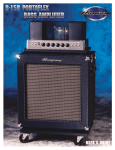
1
User’s Guide
for the
SVT-VR
Bass Amplifier
Made in the U.S.A. by
SVT-VR Bass Amplifier
TABLE OF CONTENTS
Introduction . . . . . . . . . . . . . . . . . . . . . . . . . . . . . . . . . . . . . . . .3
Features . . . . . . . . . . . . . . . . . . . . . . . . . . . . . . . . . . . . . . . . . .3
The Front Panel . . . . . . . . . . . . . . . . . . . . . . . . . . . . . . . . . . . . .4
The Rear Panel . . . . . . . . . . . . . . . . . . . . . . . . . . . . . . . . . . . . .5
Important Information About Tubes and Tube Products
A Brief History of the Tube . . . . . . . . . . . . . . . . . . . . . . . . . .6
Tube Types and Usages . . . . . . . . . . . . . . . . . . . . . . . . . . . .6
The Nature of Tubes: Why (and when) to Replace Them . . .7
The Importance of Proper Biasing . . . . . . . . . . . . . . . . . . . . .7
Survival Tips For Tube Amplifiers . . . . . . . . . . . . . . . . . . . . .8
Changing the Tubes . . . . . . . . . . . . . . . . . . . . . . . . . . . . . . . . . .9
Setting Tube Bias and Balance . . . . . . . . . . . . . . . . . . . . . . . . . .9
Some Suggested Settings . . . . . . . . . . . . . . . . . . . . . . . . . . . .10
Troubleshooting . . . . . . . . . . . . . . . . . . . . . . . . . . . . . . . . . . . .11
System Block Diagram . . . . . . . . . . . . . . . . . . . . . . . . . . . . . . .11
Technical Specifications . . . . . . . . . . . . . . . . . . . . . . . .back cover
CAUTION
PRECAUCION
ATTENTION
RISK OF ELECTRIC SHOCK
DO NOT OPEN
RIESGO DE CORRIENTAZO
NO ABRA
RISQUE D'ELECTROCUTION
NE PAS OUVRIR
WARNING: TO REDUCE THE RISK OF FIRE OR ELECTRIC SHOCK, DO NOT EXPOSE
THIS APPARATUS TO RAIN OR MOISTURE. TO REDUCE THE RISK OF ELECTRIC
SHOCK, DO NOT REMOVE COVER. NO USER-SERVICEABLE PARTS INSIDE. REFER
SERVICING TO QUALIFIED SERVICE PERSONNEL.
PRECAUCION: PARA REDUCIR EL RIESGO DE INCENDIOS O DESCARGAS ELECTRICAS, NO PERMITA QUE ESTE APARATO QUEDE EXPUESTO A LA LLUVIA O LA HUMEDAD. PARA DISMINUOIR EL
RIESGO DE CORRIENTAZO. NO ABRA LA CUBIERTA. NO HAY PIEZAS ADENTRO QUE EL USARIO
PUEDO REPARAR DEJE TODO MANTENIMIENTO A LOS TECHNICOS CALIFICADOS.
ATTENTION: PROTÉGEZ CET APPAREIL DE LA PLUIE ET DE L'HUMIDITÉ AFIN D'ÉVITER TOUT
RISQUE D'INCENDIE OU D'ÉLECTROCUTION. POUR REDUIRE D'ELECTROCUTION NE PAS ENLEVER
LE COUVERCLE. AUCUNE PIECE INTERNE N'EST REPRABLE PAR L'UTILISATEUR. POUR TOUTE
REPARATION, S'ADRESSER A UN TECHNICIEN QUALIFIE.
IMPORTANT SAFETY INSTRUCTIONS
• READ, FOLLOW, HEED, AND KEEP ALL INSTRUCTIONS AND WARNINGS.
• DO NOT OPERATE NEAR ANY HEAT SOURCE AND DO NOT BLOCK ANY VENTILATION OPENINGS ON THIS APPARATUS. FOR PROPER OPERATION, THIS UNIT REQUIRES 3”
(75CM) OF WELL VENTILATED SPACE AROUND HEATSINKS AND OTHER AIR FLOW PROVISIONS IN THE CABINET.
• DO NOT USE THIS APPARATUS NEAR SPLASHING, FALLING, SPRAYING, OR STANDING LIQUIDS.
• CLEAN ONLY WITH LINT-FREE DAMP CLOTH AND DO NOT USE CLEANING AGENTS.
• ONLY CONNECT POWER CORD TO A POLARIZED, SAFETY GROUNDED OUTLET WIRED TO CURRENT ELECTRICAL CODES AND COMPATIBLE WITH VOLTAGE, POWER, AND
FREQUENCY REQUIREMENTS STATED ON THE REAR PANEL OF THE APPARATUS.
PROTECT THE POWER CORD FROM DAMAGE DUE TO BEING WALKED ON, PINCHED, OR STRAINED.
UNPLUG THE APPARATUS DURING LIGHTNING STORMS OR WHEN UNUSED FOR LONG PERIODS OF TIME.
ONLY USE ATTACHMENTS, ACCESSORIES, STANDS, OR BRACKETS SPECIFIED BY THE MANUFACTURER FOR SAFE OPERATION AND TO AVOID INJURY.
WARNING: TO REDUCE THE RISK OF ELECTRIC SHOCK OR FIRE, DO NOT EXPOSE THIS UNIT TO RAIN OR MOISTURE.
SERVICE MUST BE PERFORMED BY QUALIFIED PERSONNEL.
OUR AMPLIFIERS ARE CAPABLE OF PRODUCING HIGH SOUND PRESSURE LEVELS. CONTINUED EXPOSURE TO HIGH SOUND PRESSURE LEVELS CAN CAUSE PERMANENT HEARING IMPAIRMENT OR LOSS. USER CAUTION IS ADVISED AND EAR PROTECTION IS RECOMMENDED IF UNIT IS OPERATED AT HIGH VOLUME.
• WARNING: THIS UNIT REQUIRES A SAFETY GROUNDED OUTLET WIRED TO CURRENT ELECTRIC CODES HAVING THE LINE SUPPLY VOLTAGE, POWER, AND FREQUENCY
IDENTIFIED ON THE REAR OF THE UNIT. THE OUTLET MUST REMAIN ACCESSIBLE TO DISCONNECT THE UNIT IF A FAULT SHOULD ARISE WHILE IN USE. THIS UNIT SHOULD
BE UNPLUGGED WHEN NOT IN USE.
•
•
•
•
•
•
EXPLANATION OF GRAPHICAL SYMBOLS:
EXPLICACION DE SIMBOLOS GRAFICOS:
EXPLICATION DES SYMBÔLES GRAPHIQUES:
"DANGEROUS VOLTAGE"
=
“VOLTAJE PELIGROSO”
"DANGER HAUTE TENSION"
"IT IS NECESSARY FOR THE USER TO REFER TO THE INSTRUCTION MANUAL"
=
“ES NECESARIO QUE EL USUARIO SE REFIERA AL MANUAL DE INSTRUCCIONES.”
"REFERREZ-VOUS AU MANUAL D'UTILISATION"
SVT-VR Bass Amplifier
An Introduction to your new Ampeg SVT-VR Bass Amplifier
The harmonically rich sound and legendary performance of the classic AMPEG SVT are reborn in the SVT-VR.
This dynamically powerful bass amp delivers a thunderous 300 watts of unsurpassed quality, reliability, and tonal
flexibility, offering the classic vibrance of tubes as well as contemporary features.
All of the features and controls of your SVT-VR are covered in detail within the pages of this user’s guide. We
recommend that you read this guide and understand them before you use the amplifier.
Features
In the world of high performance bass amps, Ampeg amplifiers stand alone. In true Ampeg tradition, the SVT-VR
offers you more power, performance and flexibility than any other bass amplifier in its class. The outstanding
features of your new amplifier, features which set it apart from the competition, are listed below.
• TWO-CHANNEL OPERATION: Two separate channels with independent tone and volume controls
• BRIGHT AND NORMAL INPUTS: Each channel offers a choice of inputs: normal or high-end
enhanced (bright)
• ULTRA HI, ULTRA LOW, BASS CUT (CH. 1 ONLY) SWITCHES: Allow you to tailor your sound in
many different ways at the touch of a button
• MIDRANGE FREQUENCY SELECT “1•2•3” SWITCH (CH. 1 ONLY): Allows you to select the
operating range for the midrange control for increased tonal flexibility
• BIAS ADJUSTMENT CONTROLS: Allow you to adjust tube bias and balance for optimal operation
• SLAVE OUT: Allows you to send a preamp signal to a secondary power amplifier
• POWER AMP IN/PREAMP OUT: A separate preamp may be connected to the Power Amp In jack,
and the Preamp Out jack may be connected to a slave amp
• TRANSFORMER BALANCED LINE OUT: Independent level control - balanced XLR output jack switchable pre or post EQ - ground lift for balanced XLR
• HEAVY-DUTY SPEAKER JACKS: Speakon® jacks for more reliable connections at higher output
Speakon® is a registered trademark of Neutrik AG.
3
SVT-VR Bass Amplifier
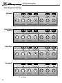
The Front Panel
1
2
3
7
8
9
4
5
6
13
10
11
14
12
15
16
1. ONE: (The Channel One Input jacks) The signal output from an instrument or a line level signal may be connected here by means of a shielded
instrument cable. Either the Bright or Normal jack may be used - the Bright
jack enhances the high frequencies of the input signal. The signal at these
jacks is sent into the Channel One preamp section (tone and volume controls).
9. BASS-CUT/OFF/ULTRA-LO: Depressing the left side of this switch
decreases the low frequency output of Channel One. Depressing the right
side of this switch enhances the low frequency output of Channel One. The
switch is inactive in the center position.
2. TWO: (The Channel Two Input jacks) The signal output from an instrument or a line level signal may be connected here by means of a shielded
instrument cable. Either the Bright or Normal jack may be used - the Bright
jack enhances the high frequencies of the input signal. The signal at these
jacks is sent into the Channel Two preamp section (tone and volume controls).
11. TREBLE: Use this control to adjust the high frequency level of the signal of Channel Two. This control provides 12dB of cut or boost at 4kHz.
The high frequency output is flat at the center position.
3. VOLUME: Use this control to adjust the output level of Channel One.
13. ULTRA-HI: This switch increases the high frequency output of
Channel Two. The Ultra Hi is active when the right side of the switch is
depressed. The amount of boost is dependent on the setting of the Volume
control (#10).
4. TREBLE: Use this control to adjust the high frequency level of the signal of Channel One. This control provides 12dB of cut or boost at 4kHz.
The high frequency output is flat at the center position.
5. MIDRANGE: Use this control to adjust the mid frequency level of the
signal of Channel One. This control provides 20dB of cut or boost at the
frequency selected by the 1•2•3 switch (#8). The midrange frequency output is flat at the center position.
6. BASS: Use this control to adjust the low frequency level of the signal of
Channel One. This control provides 12dB of cut or boost at 40Hz. The low
frequency output is flat at the center position.
7. ULTRA-HI: This switch increases the high frequency output of Channel
One. The Ultra Hi is active when the right side of the switch is depressed.
The amount of boost is dependent on the setting of the Volume control
(#3).
8. 1•2•3: This switch selects the frequency to be affected by the Midrange
control (#5). The available frequencies are 220Hz (left side of the switch
depressed), 800Hz (switch in the center position), or 3kHz (right side of the
switch depressed).
4
10. VOLUME: Use this control to adjust the output level of Channel Two.
12. BASS: Use this control to adjust the low frequency level of the signal
of Channel Two. This control provides 12dB of cut or boost at 40Hz. The
low frequency output is flat at the center position.
14. ULTRA-LO: This switch decreases the low frequency output of
Channel Two. The Ultra Lo is active when the right side of the switch is
depressed.
15. STANDBY: The Standby mode allows the tubes to warm up or remain
warm without high voltage applied to them. This helps extend the life of the
tubes. When the amplifier is first turned on, it is automatically in Standby
mode regardless of the switch position. After approximately 20 seconds,
the amp is in the mode selected by this switch. During short periods of
non-use, the amplifier should be put into Standby mode. The Standby
mode is active when this switch is in the DOWN position. The adjacent
lamp illuminates red when the amplifier is in the Standby mode.
16. POWER: This switch supplies AC power to the amplifier in the UP
position. The adjacent lamp illuminates green when the amplifier is on and
is not in Standby mode.
SVT-VR Bass Amplifier
The Rear Panel
Made In The U.S.A.
LOUD TECHNOLOGIES, INC.
17
18 19
20
17. AC LINE IN: Firmly insert the supplied AC power cord into this socket
until it is fully seated. This grounded power cord is to be plugged into a
grounded power outlet, wired to current electric codes and compatible with
voltage, power, and frequency requirements stated on the rear panel. Do
not attempt to defeat the safety ground connection.
18. (FUSE): The fuse helps protect the unit from damage due to overload
conditions. If the fuse fails, replace it only with the same size and type. If
the fuse fails repeatedly, check the line voltage or contact an Ampeg
Service Center.
19. POLARITY SWITCH: Use this switch to select the AC line voltage
polarity which yields the least electrical noise from the amplifier.
20. BIAS CONTROLS / BALANCE: Use these controls and their LEDs to
properly bias and balance the power amp. Refer to “Setting Tube Bias and
Balance” on page 7 for complete details.
21.SLAVE OUT: Use this jack to send a preamp output signal to an auxiliary power amplifier. The signal at this jack is post-EQ.
22. POWER AMP IN: This jack connects an external preamp directly to
the power amp. When using an external source, connect its output to this
jack by means of a shielded signal cable to feed the signal into the power
amp section. The internal preamp is disconnected when a plug is inserted
into this jack.
23. PREAMP OUT: Use this jack to send a signal from the internal preamp
to an auxiliary power amplifier, mixing console, monitor system, or house
PA system. The signal at this jack is post-EQ.
24. LEVEL: Use this control to adjust the signal level at the Transformer
Bal. Out jack (#27). This control works independently from the front panel
Volume controls (#3,10).
21
22
23
24 25 26
27
28
29
25. PRE (CH 1)/POST: This switch, when depressed, sends a Post-EQ
signal from Channel One to the Transformer Bal. Out jack (#27). The PostEQ signal is modified by the settings of the tone controls. With the switch
in the out position, the Channel One signal sent to the Transformer Bal.
Out jack is Pre-EQ. The Pre-EQ signal is a direct output and is not affected by any of the preamp settings.
30. LIFT/GND: This switch, when depressed, connects the ground connection at the Transformer Bal. Out jack (#27). This may help reduce residual hum and buzz sometimes picked up in line out signal cables.
27. TRANSFORMER BAL. OUT: Use this XLR jack to send a balanced
line level signal to a house mixing board, recording console, or external
amplifier. The signal level at this jack is controlled by the Level control (#24)
and may be Pre or Post-EQ depending on the setting of the Pre/Post
switch (#25).
28. IMPEDANCE SELECTOR: Use this switch to match the output impedance of the amplifier to the overall impedance rating of your cabinet(s). The
following chart shows total impedance for speaker cabinets used in parallel.
Cabinet
Impedance
2 ohms
4 ohms
4 ohms
8 ohms
8 ohms
Number of
Cabinets
1
1
2
2
4
Total
Impedance
2 ohms
4 ohms
2 ohms
4 ohms
2 ohms
29. SPEAKER OUTPUTS: Use these jacks to connect the amplifier to
your speaker cabinet(s). The 1/4” jacks offer a convenient method of connecting to speaker cabinets using cables terminated with 1/4” plugs.
However, when using the amplifier at or near its full output power, using the
Speakon® jacks is recommended. (Pin 1+ = hot, pin 1- = return.)
5
SVT-VR Bass Amplifier
Important Information About Tubes and Tube Products
A Brief History Of The Tube:
In 1883, Edison discovered that electrons would flow from a suspended filament when enclosed in an evacuated lamp. Years later,
in 1905, Fleming expanded on Edison's discovery and created the "Fleming Valve". Then, in 1907, Dr. Lee de Forest added a third
component – the grid – to the "Fleming's Valve" and the vacuum tube was a fact of life. The door to electronic amplification was
now open.
During World War II, data gleaned from their intensive research on the detectors used in radar systems led Bell Telephone
Laboratories to the invention of the transistor. This reliable little device gained quick support as the new component for amplification. The death of the vacuum tube seemed imminent as designers, scientists, and engineers reveled in the idea of replacing large,
fragile glass tubes with these small, solid-state devices.
However, there were (and still are) many serious listeners who realized that the sound produced by a "transistor" amplifier is significantly different from that produced by a tube amplifier with identical design specifications. They considered the sound produced
by these new solid-state devices to be hard, brittle, and lifeless. It was determined that solid-state devices produced a less musical set of harmonics than tubes. When pushed past their limits, they tend to mute the tone and emphasize the distortion.
Tubes, on the other hand, produce a more musical set of harmonics, the intensity of which can be controlled by the player. This
characteristic adds warmth and definition to the sound which has become the hallmark of tube amplifiers. When tubes are driven
into clipping, the harmonic overtones can be both sweet and pleasing or intense and penetrating, depending on the musician’s
musical taste and playing technique.
Over the years, application engineers have designed a number of outstanding solid-state amplifiers that sound very, very good.
Some use special circuitry which enables them to simulate the distortion characteristics of a tube amplifier. However, the tube
amplifier, still held in the highest esteem by many musicians, offers a classic "vintage" sound in a contemporary market.
Tube Types And Usage:
Tube amplifiers are based primarily on two types of tubes – preamplifier tubes and power tubes. The tubes used in preamplifiers (12AX7, 12AU7, 12AT7, etc.) are smaller than the power tubes. These tubes amplify the signal from your instrument and
shape the sound. They are inherently microphonic (mechanically pick up and transmit external noises). Since these tubes are
used in the critical first stages of a tube amplifier's circuitry, it is very important to use high-quality, low noise/low microphonic
tubes for this application. Although tubes of this quality may be difficult to find and typically cost more than "off-the-shelf" tubes,
the improvement in performance is worth the investment.
Preamplifier tubes are also used to drive the power tubes. When used in this application, a 12AX7 will produce a more distorted
tone than a 12AT7, which produces a clearer, sweeter sound. A 12AU7 is even cleaner and brighter than a 12AT7, giving more
definition to the sound. (In some cases it is possible to change the sound by changing the type of preamp and/or driver tubes.
When making any modification to your equipment, it is highly recommended that you consult with a qualified service center.)
The power tubes are the largest tubes used in an amplifier. These tubes convert the low-level, conditioned signal from the preamplifier into a level that is sufficient to drive the speakers. There are several types of power tubes available, each of which
offers a different performance/sound characteristic. For example, the EL34 power tube produces a great Classic rock sound.
When an EL34 is driven into distortion it produces a unique sound ("crunch"). When compared to the 6L6, the EL34 distorts
more quickly, exhibits a "looser" low-end response and produces more harmonics at mid and high frequencies ("creamier"
sound). These differences become more noticeable at higher volumes.
The 6L6 tubes produce a big low-end thump and have a very good dynamic range. They offer a more traditional "American
Rock" sound. The 6V6 tubes produce a creamy sound with nice distortion. On the other hand, the KT88 produces a big low-end
but sounds more like an EL34 in the mid and high frequencies.
The 6550 power tubes are more rugged and stay cleaner sounding even at full power. When they do distort, the sound produced is more solid and has a tighter low end; more of a "heavy metal" type distortion with lots of power.
Some tubes are available in matched sets. These tubes have been extensively tested for optimum performance and longevity.
6
SVT-VR Bass Amplifier
Important Information About Tubes and Tube Products
The Nature Of Tubes: Why (And When) To Replace Them:
Tubes are made up of a number of fragile mechanical components that are vacuum-sealed in a glass envelope or bubble. The tube's
longevity is based on a number of factors which include how hard and often the amplifier is played, vibration from the speakers, road travel, repeated set up and tear down, etc.
Any time you notice a change in your amplifier's performance, check the tubes first.
If it's been a while since the tubes were replaced and the sound from your amplifier lacks punch, fades in and out, loses highs or lows or
produces unusual sounds, the power tubes probably need to be replaced. If your amplifier squeals, makes noise, loses gain, starts to hum,
lacks "sensitivity", or feels as if it is working against you, the preamplifier tubes may need to be replaced.
The power tubes are subjected to considerably more stress than the preamplifier tubes. Consequently, they almost always fail/degrade first.
If deteriorating power tubes aren't replaced they will ultimately fail. Depending on the failure mode, they may even cause severe damage to
the audio output transformer and/or other components in the amplifier. Replacing the tubes before they fail completely has the potential to
save you time, money and unwanted trouble. Since power tubes work together in an amplifier, it is crucial that they (if there is more than
one) be replaced by a matched set. If you're on the road a lot, we recommend that you carry a spare matched set of replacement power
tubes and their associated driver tubes.
After turning off the power and disconnecting the amplifier from the power source, carefully check the tubes (in bright light) for cracks or white
spots inside the glass or any other apparent damage. Then, with the power on, view the tubes in a dark room. Look for preamplifier tubes
that do not glow at all or power tubes that glow excessively red.
Whenever you replace the power tube(s):
• Always have the amplifier's bias voltage checked by a qualified service center. Improper bias voltage will cause degradation in performance and possibly damage the tubes and/or the amplifier. (See the section below entitled, "The Importance of Proper Biasing", for more
information on this subject).
• We highly recommend that you replace the driver tube(s) as well. The driver tube determines the shape and amplitude of the signal applied
to the power tube(s) and has to work almost as hard as the power tube(s).
You can check your preamplifier tubes for microphonics by turning the amplifier on, turning up the gain and tapping lightly on each tube with
the end of a pencil or a chop stick (my favorite). You will be able to hear the tapping through your speakers, which is normal. It is not normal for a tube to ring like a bell after it’s tapped. If it does ring then it’s microphonic and should be replaced. Remember to use only high
quality, low microphonic tubes in the preamplifier section.
Even though power tubes are rarely microphonic, you should check them anyway. The power tubes can be checked for microphonics just
like pre-amp tubes.
In the case of very high gain amps, you may be able to reduce the amount of noise generated by simply swapping the preamp tubes around.
The Importance Of Proper Biasing:
For the best performance and longest tube life, proper biasing is imperative. Bias is the negative voltage which is applied to the power tube’s
control grid to set the level of idle current. We cannot over emphasize the difference in warmth of tone and dynamic response that come
with proper biasing. If the bias is set too high (overbiased), the sound from the amp will be distorted at all levels. If the bias is set too low,
(under biased) the power tubes will run hot (the plates inside the tubes may glow red due to excessive heat) and the sound from the amplifier will lack power and punch. The excessive heat greatly reduces tube life – from a few days to as little as a few hours in extreme cases.
Setting the bias on your amp is like setting the idle on your car. If it’s too high or hot it’s running away with you and if it’s too low or cold it will
choke when you step on it.
The bias is adjusted at the factory in accordance with the type of power tube(s) installed in your amplifier. It is important to point out that
tubes of the same type and specification typically exhibit different performance characteristics. Consequently, whenever power tubes are
replaced, the bias voltage must be checked (unless the amplifier is equipped with “self-biasing circuitry”) and readjusted to accommodate
the operating parameters of the replacement tubes.
Depending on the model and amplifier type, there may be hum balance controls, trim pots, or bias adjustment controls on its rear panel.
However, the bias adjustment should be performed only by qualified service personnel with the proper, calibrated test equipment.
7
SVT-VR Bass Amplifier
Important Information About Tubes and Tube Products
Survival Tips For Tube Amplifiers:
To prolong tube life, observe these tips and recommendations:
• Match the impedance of your speaker cabinet(s) to your amplifier. Improper impedance matching will contribute to early tube
degradation and may cause premature tube failure.
• Make sure the speaker(s) are properly connected prior to turning on the amplifier.
• After playing the amplifier, allow sufficient time for it to properly cool down prior to moving it. A properly cooled amplifier prolongs tube life due to the internal components being less susceptible to the damage caused by vibration.
• Allow the amplifier to warm up to room temperature before turning it on. The heat generated by the tube elements can crack a
cold glass housing.
• Replace the output tube(s) before the performance degrades or the tubes fail completely. Replace the tube(s) on a regular
basis (at least once per year or as often as every 4 to 6 months if you play long and hard every day).
• Always have the bias checked after replacing the output tubes (unless the amplifier is equipped with "self-biasing circuitry").
This should be done ONLY at a qualified service center. Improper biasing could result in the tubes running too hot, which
greatly reduces the life of the tubes – or too cold, which results in distorted sound regardless of level settings. Do not play the
amplifier if it exhibits these symptoms – get the bias checked/adjusted immediately to prevent tube failure and/or other damage.
• If the locating notch on the base of a power tube breaks off, replace the tube. This significantly reduces the risk of damaging
your amplifier by incorrectly inserting the tube.
• Protect the amplifier from dust and moisture. If liquid gets into the amplifier proper, or if the amplifier is dropped or otherwise
mechanically abused, have it checked out at an authorized service center before using it.
• Proper maintenance and cleaning in combination with routine checkups by your authorized service center will insure the best
performance and longest life from your amplifier.
CAUTION: Tube replacement should be performed only by qualified service personnel who are familiar with the dangers of hazardous voltages that are typically present in tube circuitry.
8
SVT-VR Bass Amplifier
Changing The Tubes
Tubes wear out in direct proportion to how often and how hard you use the amplifier. Power tubes should be
checked at least once a year - more frequently if you use the amplifier nearly every day. When power tubes wear
out, the amplifier will begin to grow weak, lack punch, fade up and down, or lose highs and lows. Power tubes work
together in a push/pull configuration and should all be replaced at the same time with matched or balanced tubes.
Your dealer can recommend the best replacement tubes for your amplifier.
Preamp tubes aren’t worked as hard as power tubes and typically last longer. When a preamp tube wears out,
the amplifier may squeal, get noisy, lose gain and sensitivity, or just quit working. A service center can determine
which tube(s) may need replacing.
To get to the power tubes in the SVT-VR, the rear screen must be removed and the tube retainer(s) must be
moved out of the way. Qualified service persons may follow these steps to change the tubes:
• Turn the amp off, unplug it and let it cool for at least 5 minutes.
• Remove the screws which hold the perforated metal screen to the rear of the cabinet.
• Set the perforated metal screen aside.
• Remove the tube retainer(s) by lifting them off the tube(s) and moving them to one side.
• Grasp the tube at its top and gently work it out of its socket by rocking it slightly back and forth as you lift
up on it.
• When inserting new output tubes, align the tab in the tube’s plastic base with the slot in the socket and
press the tube gently but firmly into place by puching down on its top.
• Replace the perforated metal screen and tighten its screws.
• Power up the amplifier and let it sit for at least 20 minutes. Bias and balance the amplifier as directed in
the section below.
Setting Tube Bias and Balance
Tube Bias:
Allow the amplifier to warm up to proper AC line voltage for at least 20 minuts. With no input signal present,
adjust each bias control until its adjacent LED illuminates.
The Bias 1 control affects the three power tubes on the left (as viewed from the rear). The Bias 2 control affects
the three power tubes on the right (as viewed from the rear).
Balance:
Insert a 40Hz signal into the amplifier. Adjust the Volume control for approximately 25 VRMS output. Slowly
adjust the Balance control until its adjacent LED illuminates.
9
SVT-VR Bass Amplifier
Some Suggested Settings
Standard:
*
Back Pickup
Fretless:
*
Hard Edge:
*
“Scooped:”
*
*
10
= as needed
SVT-VR Bass Amplifier
Troubleshooting
In the unlikely event that your SVT-VR should malfunction, take a few minutes to troubleshoot it before you call for
service. You can save yourself time and money by doing it yourself, and often the problem is something quite simple.
If the problem isn’t covered above, or if the steps lead you here, then contact your Ampeg dealer for service information. Also, you should refer your amp to an authorized service center if it gets dropped, has liquid spilled into it, or sustains
damage to its power cord. Regular cleaning and maintenance by your local Service Center will help extend the useful life
of the amplifier.
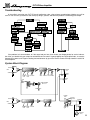
System Block Diagram
BRIGHT
PREAMP
OUT
ONE
NORMAL
MIDBASS TREBLE 1•2•3 RANGE
ULTRA ULTRA VOLUME
HIGH
LOW
POWER
AMP IN
SLAVE
OUT
PRE
POST
TRANSFORMER
BAL. OUT
LEVEL
LIFT
GND
POWER
AMP
BRIGHT
4 OHM
2 OHM
SPEAKERS
TWO
NORMAL
ULTRA ULTRA VOLUME
HIGH
LOW
BASS TREBLE
BIAS
1
BALANCE
BIAS
2
1+
12+
2- (SPEAKON
JACK)
11
SVT-VR Bass Amplifier
Technical Specifications
OUTPUT POWER RATING
300 Watts RMS minimum continuous @ <5% THD into 2 or 4 ohms, 0.25V RMS input
TOTAL SYSTEM GAIN
channel one: 66dB @ 1kHz with volume up and tones flat
channel two: 59dB @ 1kHz with volume up and tones flat
TONE CONTROL RANGE
channel one:
treble:
midrange:
bass:
ultra high:
ultra low:
bass cut:
channel two:
treble:
bass:
ultra high:
ultra low:
SIGNAL TO NOISE RATIO
channel one:
channel two:
TUBE COMPLEMENT
POWER REQUIREMENTS
SIZE AND WEIGHT
±12dB @ 4kHz
±20dB @ 220, 800, or 3kHz
±12dB @ 40Hz
+15dB @ 8kHz (volume @ 50%)
-20dB @ 600Hz
-20dB @ 40Hz
±12dB @ 4kHz
±12dB @ 40Hz
+15dB @ 8kHz (volume @ 50%)
-11dB @ 40Hz (relative)
75dB typical
75dB typical
12AX7 (4), 12AU7 (4), 6550 (6)
120VAC, 60Hz, 400VA
100/115VAC 50/60Hz, 400VA
230VAC, 50/60Hz, 400VA
24” W x 11-1/2” H x 12-3/4” D; 85 lbs
Ampeg reserves the right to change specifications without notice.
Declaration of Conformity
Manufacturer’s Name: LOUD Technologies
Corporate Headquarters: 16220 Wood-Red Road NE, Woodinville, WA 98072 USA
Primary Production Facility: 700 Hwy 202 W, Yellville, Arkansas, 72687
Product Type: Audio Amplifier
Products meet the regulations for compliance marking under:
ETL standards UL6500, UL60065, or UL813
CSA standards E60065 or C22.2 No.1-M90
CE safety standard EN60065
CE EMC standards EN55103 or EN55013 and EN61000
FCC standards 47CFR 15.107 and 15.109 Class A
C-tick designation Level 2, ABN #56748810738, ARBN# N222
KETI standard K60065 (limited model approval)
Compliance Support Contact: LOUD Technologies, Attn: Compliance Manager
16220 Wood-Red Road NE, Woodinville, WA 98072 USA • Tel.: +1 425 892 6500, Fax: +1 425 487 4337
www.ampeg.com
Made with Pride in the U.S.A. by Ampeg • ©2006 LOUD Technologies, 16220 Wood-Red Road NE, Woodinville, WA 98072 USA
P/N 47-437-01 . 032306