1
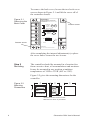
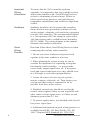
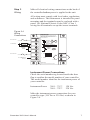
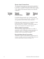
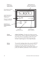
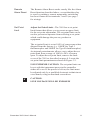
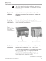
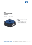
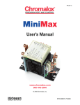
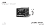
3901
Chromalox
®
Overtemperature Controller
Chromalox
UL
®
FM
APPROVED
Issue Date
Dec 1993
User’s Manual
0037-75121
Table of Contents
Sections
Section
Topic
Page
1
2
3
4
5
6
Introduction to the 3901 Controller
Installation
Operation
Calibration
Specifications
Warranty and Return Information
1
3
9
13
15
17
Figure
Topic
Page
1.1
1.2
Overtemperature Control Application
Model Identification Table
1
2
2.1
2.2
2.3
2.4
Removing the Back Cover
Mounting Dimensions
Mounting Diagram
Wiring Connections
4
4
5
7
3.1
3.2
Front Panel Identification
Set Point Limit Potentiometer
10
12
4.1
Zero and Span Calibration Potentiometer
13
Illustrations
i
Chromalox 3901 User’s Manual
Section 1
Introduction to the
3901 Controller
The Chromalox 3901 Overtemperature Controller
gives you reliable and economical digital indicating,
overtemperature control in a compact 1/4 DIN
package. Figure 1.1 illustrates a typical overtemperature application.
Figure1.1
Overtemperature Control Application
3901
HEAT
SOURCE
SHUTDOWN
CONTACTOR
°F
READ
TEMP
ALARM
Chromalox
OVERTEMP FOR PROCESSOR HEATER SHEATH PROTECTOR
3901
°F
READ
TEMP
FLOW
SWITCH
LEVEL
CONTROL
AIR
FLOW
LEVEL
SENSOR
SHUTDOWN
CONTACTOR
ALARM
Chromalox
HEAT
SOURCE
OVERTEMP APPLIED WITH OTHER CUTOUT DEVICES
Chromalox 3901 User’s Manual
1
Before You
Install
Before proceeding with installation and operation of
your controller, it is important that you identify the
model you have purchased. This will determine how
you install and wire the controller, and how you may
apply it. Check the serial number tag on the inside
front door flap of the controller to confirm your
model number.
Figure 1.1
Model Identification Table
Model
Overtemperature Controller
3901
Digital Indicating, UL Listed, FM Approved, Terminals for Remote Reset;
1/4 DIN Panel Cutout, 2.4 Inch Depth Behind Panel
3901-
2
Code
Control Output
1
Relay, up to 230 Vac, 20 amp resistive load, SPST Latching,
Normally-Energized, Normally-Open Contact
1
Code
Terminations
1
Barrier Strip with Screw Terminals
1
Code
Instrument Power
1
2
120 Vac, +10%, -15%, 50/60 Hz
230 Vac, +10%, -15%, 50/60 Hz
1
Code
Input Type/Indication Range
04
08
12
18
Type J Thermocouple, 0-999°F
Type J Thermocouple, 0-500°C
Type K Thermocouple, 0-1999°F
Type K Thermocouple, 0-1100°C
04
Typical Model Number
Chromalox 3901 User’s Manual
Section 2
Installation
Inspection &
Unpacking
On receipt of your 3901 controller, immediately make
note of any visible damage to the shipment packaging
and record this damage on the shipping documents.
Unpack the controller and carefully inspect it for
obvious damage due to shipment. If any damage has
occurred, YOU must file a claim with the transporter,
as they will not accept a claim from the shipper.
Storage
If the controller will not be immediately installed and
placed into operation, it should be stored in a cool, dry
environment in its original protective packaging until
time for installation and operation. Temperature
extremes and excessive moisture can damage the
instrument.
Installation
Steps
Installation of the 3901 controller requires 3 steps:
Step 1 - Accessing Internal Adjustments
Step 2 - Mounting
Step 3 - Wiring
Step 1
Accessing
Internal
Adjustments
The back cover of the 3901 can be easily removed to
access the following internal adjustment:
• Set Point Limit Potentiometer (page 11)
The page number referenced above describes this
internal adjustment. Although it is not necessary, it is
easier to make this adjustment prior to mounting
and wiring the controller. If you want to establish a
Set Point Limit for your controller, read the page
referenced above before mounting and wiring the
3901.
Chromalox 3901 User’s Manual
3
To remove the back cover, loosen the two back cover
screws shown in Figure 2.1 and lift the cover off of
the controller chassis.
Figure 2.1
Removing the
Back Cover
WARNING
TO REDUCE THE RISK OF FIRE OR ELECTRIC
SHOCK, PANEL MOUNT IN A CONTROLLED
ENVIRONMENT ENCLOSURE RELATIVELY FREE
OF CONTAMINANTS.
Loosen screw
1
INTERNAL
ALARM
RELAY
2
UL
LISTED
35MO
®
RELAY RATING
20A RES 55 C 120/230 VAC
3
REMOTE
RESET
FM
APPROVED
4
Loosen screw
5
HAC
6
LAC/N
120 V AC
230 VAC
5 VA
+
7
8
TC INPUT
CASE GND
NOTE: USE COPPER CONDUCTORS ONLY
After completing the internal adjustment(s), replace
the cover and re-secure the two screws.
Step 2
Mounting
The controller should be mounted in a location free
from excessive dust, oil accumulations and moisture.
It may be mounted in any position at ambient
temperatures of 30°F to 130°F (0°C to 55°C).
Figure 2.2 gives the mounting dimensions for the
controller.
3.8
(96)
Figure 2.2
Mounting
Dimensions
3.8
(96)
READ
TEMP
.8
(19)
ALARM
2.4
(61)
3.6
(92)
3.5
(89)
Chromalox
PANEL CUTOUT
Measurements are shown in inches.
Millimeters are shown in parenthesis.
4
Chromalox 3901 User’s Manual
1. Cut a square mounting hole (3.6” x 3.6”) in the
panel or mounting surface and place the controller
through the cutout.
2. Two mounting brackets are provided to secure the
controller in the cutout. Loosen the screws on the two
brackets. Place the mounting tabs into the mounting
holes located on the sides of the controller.
3. From the rear of the controller, tighten the screws
until the brackets are tight against the panel, securing
the controller in the panel cutout.
4. For other mounting configurations, the mounting
bracket tabs may be placed in the controller casing
vent slots.
Figure 2.3
Mounting
Diagram
Mounting Hole
Mounting Tab
Loosen Screw
Chromalox 3901 User’s Manual
5
Important
Wiring
Information
To insure that the 3901 controller performs
optimally, it is imperative that you read this section
and become familiar with “Good Wiring Practices”
critical to eliminating electrical noise. Failure to
follow good wiring practices can result in poor
temperature measurement and ineffective high limit
control.
Snubbers
Snubbers should be used to protect the controller
from electrical noise generated by inductive loads
such as motors, solenoids, coils and relays operating
near the 3901 controller. The recommended snubber
is a .1uf capacitor (600 Vdc rating) in series with a
100 ohm resistor and is available from Chromalox
(PCN 314448). The wiring diagram in this manual
illustrates the snubber connection.
Good
Wiring
Practice
Read and follow these Good Wiring Practices when
connecting this and any other controller:
1. Do not run sensor leadwires and power leads
together in the same conduit or wire tray.
2. When planning the system wiring, be sure to
consider the importance of separating wiring into
functionally similar bundles—i.e. power leads,
sensor leads, output signal lines, etc. If the power
leads and sensor leads must cross, they should cross
at a 90° angle to each other (perpendicular).
3. Locate all sources of noise in your system—
motors, contacts, solenoids, etc. Then design your
system such that wiring is separated as far as
possible from these noise sources.
4. Shielded, twisted wire should be used for the
control circuit signals if they are run in parallel with
other control circuit signal wires, or if they are run
distances greater than 2-3 feet.
5. To protect against noise, use shielded cables for all
low power signal lines.
6. Additional information on good wiring practices is
available from IEEE, 345 East 47th St., NY, NY
10017. Request IEEE Standard No. 5128-1982.
6
Chromalox 3901 User’s Manual
Step 3
Wiring
Make all electrical wiring connections on the back of
the controller before power is applied to the unit.
All wiring must comply with local codes, regulations
and ordinances. This instrument is intended for panel
mounting and the terminals must be enclosed with a
panel. Use National Electric Code (NEC) Class 1
wiring for all terminals except the sensor terminals.
Figure 2.4
Wiring
Connections
WARNING
TO REDUCE THE RISK OF FIRE OR ELECTRIC
SHOCK, PANEL MOUNT IN A CONTROLLED
ENVIRONMENT ENCLOSURE RELATIVELY FREE
OF CONTAMINANTS.
120 or 230 VAC
AC NEUTRAL
1
UL
INTERNAL
ALARM
RELAY
LOAD
2
SNUBBER
LISTED
35MO
®
RELAY RATING
20A RES 55 C 120/230 VAC
3
REMOTE
RESET
REMOTE
RESET
FM
APPROVED
4
120 or 230 VAC
5
AC COMMON OR
230 VAC
6
HAC
120 V AC
230 VAC
5 VA
+
7
+
LAC/N
8
TC INPUT
CASE GND
NOTE: USE COPPER CONDUCTORS ONLY
Instrument Power Connections
Check the serial number tag located inside the door
flap to confirm the model number of your controller.
The model number identifies the instrument power of
your controller.
Instrument Power
3901 - **1**
3901 - **2**
120 Vac
230 Vac
Make the instrument power connections for your
controller type (120 Vac or 230 Vac) as shown in
Figure 2.4.
Chromalox 3901 User’s Manual
7
Sensor Input Connections
The thermocouple input is connected at terminals 7
(+) and 8 (-) as indicated by the wiring decal on the
back of the controller. The table below shows typical
color coding for the thermocouples used with this
controller:
T/C Type
J
K
Material
Iron/Constantan
Chromel/Alumel
Plus(+)
White
Yellow
Minus (-)
Red
Red
If shielded thermocouple wire is used, the shield
must be grounded at one end only, preferably at the
case ground (CASE GND) of the controller.
If thermocouple extension wire is required, it must
be the same type of extension wire as the
thermocouple (for example, if the thermocouple is
Type J, the extension wire must be Type J).
Alarm Output Connection
The alarm relay output connections are made at
terminals 1 and 2. Make the wiring connections as
shown in Figure 2.4, using the recommended
snubber circuit as discussed on page 6.
Remote Alarm Reset Connection
Terminals 3 and 4 are provided for connection of a
remote, normally-open reset switch. Make the reset
switch connection as shown in Figure 2.4.
8
Chromalox 3901 User’s Manual
Section 3
Operation
Before applying power to the controller and
proceeding with Operation, verify that all wiring is
correct.
In this section you will learn how to make the
following selections and adjustments:
Set Point
Alarm Reset
Remote Alarm Reset
Set Point Limit
Initial
Power-Up
When power is applied to the 3901, it will begin
operating using the factory-set alarm set point shown
in the digital display. The process temperature
measured by the thermocouple can be selected for
display by pushing the “READ TEMP” pushbutton.
The ALARM LED will be illuminated only if the
process temperature is at or above the set point
temperature, or if the thermocouple is open.
The 3901’s front panel displays and indications, and
the RESET pushbutton and Set Point adjustment knob
located behind the front door flap are shown in Figure
3.1. Familiarize yourself with the front panel before
proceeding in this section.
Chromalox 3901 User’s Manual
9
Digital Display for
Alarm Set Point and
Process Temperature
Figure 3.1
Front Panel
Identification
Overrange and Open
Sensor Indicator
854
Hold Pushbutton to
Display Process
Temperature
°F
READ
TEMP
ALARM
Release Pushbutton
to Display Set Point
SET POINT
Pushbutton to
Reset Latching
Overtemperature
Alarm
RESET
Set Point
Adjustment Knob
10
LED Indicates
Alarm Condition
Alarm
Set Point
Adjust Set Point—To adjust the alarm set point,
locate the SET POINT adjustment behind the front
door flap. Insert a screwdriver in the hole in the
knob, and turn the SET POINT knob until the
desired set point appears in the digital display.
Alarm
Reset
To reset the latching alarm relay, press the RESET
switch located behind the front door flap. If you
attempt to reset the alarm before the process
temperature has reached a normal state (below set
point), the RESET pushbutton will be ineffective.
Chromalox 3901 User’s Manual
Remote
Alarm Reset
The Remote Alarm Reset works exactly like the Alarm
Reset function described above, except that the relay
is reset by pushing a remote momentary switch that
has been connected to terminals 3 and 4 (see page 7
for wiring).
Set Point
Limit
Adjust Set Point Limit—The 3901 has a set point
limit feature that allows you to preset an upper limit
for the set point adjustment. The set point limit can be
used to prevent an operator from selecting a set point
which could damage the process, product or
equipment.
The set point Limit is set at 100% of sensor span when
shipped from the factory (i.e. 1000°F for Type J
thermocouples and 2000°F for Type K thermocouples).
An internal potentiometer allows you to adjust the set
point limit from a range of 100% to 20% of sensor
span. To adjust the set point limit, remove the back
cover of the 3901 as described on page 4. Locate the
set point limit potentiometer shown in Figure 3.2.
USE EXTREME CAUTION: The set point limit can
be set with the instrument power to the controller
either off or on. If the power is left on, the limit must
be adjusted only by a qualified electronic technician at
a test bench, using an insulated screwdriver.
☛
CAUTION:
LINE VOLTAGE WILL BE EXPOSED!
Chromalox 3901 User’s Manual
11
Figure 3.2
Set Point Limit
Potentiometer
Chromalox
Set Point Limit
Screwdriver
Controller Bottom View
To adjust the set point limit:
1. Turn the SET PT knob on the front faceplate to its
full clockwise position (FULL ON).
2. Turn the set point limit potentiometer until the
digital display reads the desired set point limit. In the
full (clockwise) position, the set point limit is 100%,
or more, of span.
3. After reaching the desired set point limit setting,
be sure to readjust the process set point to the
application’s setting using the SET PT knob.
To verify the set point limit setting, attempt to adjust
the set point past the set point limit.
12
Chromalox 3901 User’s Manual
Section 4
Calibration
☛
The 3901 controller has been calibrated and tested at
the factory prior to shipment. Calibration on receipt is
not necessary.
Equipment
Required
A precision thermocouple simulator and a small
instrument screwdriver are necessary to calibrate the
controller.
Locating
Calibration
Adjustments
Remove the back cover from the controller as
described on page 4. Figure 4.1 identifies the zero and
span calibration potentiometers.
➛
Figure 4.1
Zero and Span
Calibration
Potentiometers
Zero Potentiometer
Calibration
Procedure
Span Potentiometer
1. Connect the sensor simulator to terminals 7 and 8,
making sure to connect the (+) to 7 and (-) to 8.
2. Set the sensor simulator to a minimum value (200°F
for J T/C, 350°F for K T/C). While pressing the
“READ TEMP” pushbutton, adjust the zero
potentiometer until the digital display equals the
sensor input value (200°F or 350°F).
(continued on next page)
Chromalox 3901 User’s Manual
13
Calibration
Procedure
(continued)
3. Set the sensor simulator to a maximum (900°F for
J T/C, 1600°F for K T/C). While pressing the
“READ TEMP” pushbutton, adjust the span
potentiometer until the digital display equals the
sensor input value (900°F or 1600°F).
4. Repeat steps 2 and 3 as many times as necessary
until both displays equal their respective sensor input
values.
5. Calibration complete.
14
Chromalox 3901 User’s Manual
Section 5
Specifications
Alarm Output
Alarm Relay
Normally-open, normally-energized, SPST, latching
relay (contacts open on alarm & when no power is
applied to controller - failsafe)
Rating at 120 or 240 Vac (resistive load):
20 amps, 150,000 operations
15 amps, 200,000 operations
5 amps, 800,000 operations
Mechanical life, 10 million operations
Repeatability
+/- 1°F or 1°C
Reset
Differential
5°F or 3°C, nominal
Input
Specifications
Type J
Thermocouple
0 to 999°F, 0 to 500°C
Type K
Thermocouple
0 to 1999°F, 0 to 1100°C
Input Loop
Resistance
Up to 150 ohms
Cold Junction
Compensation
Automatic, typically less than 0.1°F per 1°F over
ambient 50 to 120°F
Indications
Open Sensor
Indications
Red LED lamp for J thermocouple input, “1”
illuminates for K thermocouple input Upscale burnout,
alarm indication, contacts open
Accuracy of
Indication
+/- 0.5% of span over mid-80% of scale
Resolution
1°F or 1°C
Repeatability
1°F or 1°C
Alarm Output
Red “ALARM” LED
Chromalox 3901 User’s Manual
15
General
Instrument
Power
120 or 230 Vac, +10%, -15%, 50/60 Hz, 10 VA
nominal power consumption
Operating
Environment
30 to 130°F with relative humidity less than 95%
non-condensing
Dimensions
Requires 3.6” x 3.6” (92 mm x 92mm) panel cutout
Depth behind panel of 2.4” (61 mm)
Projection at front of panel 0.8” (20 mm)
Mounting
Two screw-in mounting brackets to secure controller
in panel
Influence of
Line Voltage
Variation
Maximum change of +/- 1°F for +/- 10% nominal
line voltage change
Noise Rejection
16
Common
Mode
Less than 2°F with 230 Vac, 60 Hz applied from
sensor input to instrument case
Series Mode
Less than 2°F with 100 mV, peak to peak series
mode noise
Chromalox 3901 User’s Manual
Section 6
Warranty and Return
The warranty complies with the Federal Law
applicable to products manufactured after December
31, 1976. This warranty gives you specific legal rights.
You may also have other rights which vary from state
to state.
Warranty
Chromalox Instruments and Controls’ products are
warranted against defects in workmanship and
materials. No other express warranty, written or oral,
applies with the exception of a written statement from
an officer of Chromalox Instruments and Controls,
Wiegand Industrial Division, Emerson Electric Co.
Warranty
Period
This warranty extends for twelve months from the date
of shipment from the factory or an authorized
distributor.
Limitations
Products must be installed and maintained in
accordance with Chromalox instructions. Users are
responsible for the suitability of the products to their
application. There is no warranty against damage
resulting from corrosion, misapplication, improper
specification or other operating conditions beyond our
control. Claims against carriers for damage in transit
must be filed by the buyer.
Returns
Items returned to Chromalox Instruments and Controls
must be accompanied by a Return Authorization
Number. This number may be obtained from
Chromalox Instruments and Controls, Customer
Service Department, Telephone Number (615) 7933900. It should appear on the exterior of the shipping
carton and on the shipping documents. Defective items
will be repaired or replaced at our option, at no charge.
Return the defective part or product, freight prepaid,
to:
Chromalox Instruments and Controls
1382 Heil-Quaker Blvd.
LaVergne, TN 37086-3536
Chromalox 3901 User’s Manual
17