1
Save This Manual
For Future Reference
Sears
owners
manual
MODEL NO.
113.199200
SAW ONLY
113.199250
SAW WITH
LEGS
Serial
Number
Model and serial
number may be found
at the front of the base.
You should
model
record
and serial
in a safe place
future
CRRFTSMRN
both
number
for
use.
IO-INCH
RADIAL
CAUTION:
Read GENERAL
and ADDITIONAL
SAFETY
• assembly
INSTRUCTIONS
• operating
carefully
• repair
Sold
Part
No.
63888
by SEARS,
ROEBUCK
AND
SAW
parts
CO.,
Chicago,
IL. 60684
U.S.A.
Printed
in U.S.A.
FULL ONE YEAR
If within
one
year
from
workmanship,
Sears
WARRANTY
SERVICE
the
will
IS
CENTER/DEPARTMENT
THIS
APPLIES
gives
you
purchase,
free
ONLY
BY
safety
Craftsman
SIMPLY
THE
WHILE
legal
ROEBUCK
this
ON CRAFTSMAN
Radial
RADIAL
Saw
fails
due
SAW
to a defect
in material
or
of charge.
AVAILABLE
specific
SEARS,
general
of
it,
THROUGHOUT
WARRANTY
This warranty
date
repair
WARRANTY
UNITED
THIS
rights,
AND
and
CO.
CONTACTING
PRODUCT
you
THE
NEAREST
SEARS
SERVICE
STATES.
may
DEPT.,
instructions
IS IN USE
have
other
698/731A
IN THE
rights
Sears
UNITED
which
Tower,
STATES.
vary
from
Chicago,
state
to state.
IL 60684
for power
tools
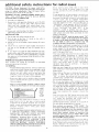
1. KNOW YOUR POWER TOOL
Read and understand
the owner's
manual
and labels
affixed
to the tool. Learn _ts applications
and limitations
as welt as the specific potentiaI
hazards peculiar to this
tool.
2. GROUND
ALLTOOLS
lhis
toot
s equipped
with an approved
3-conductor
cord
and + 3-prong
grounding
type plug to fit the
proper grounding
type receptacle.
The green conductor
ill [he cord is the grounding
wire. Never connect the
greerl
wire
',o a live terminal,
3. KEEP GUARDS
hr workirrg
alignment.
IN PLACE
order,
and
in
4. REMOVE ADJUSTING
AND WRENCHES
proper
adjustment
and
KEYS
KEEP
WORK
Cluttered
must not
AREA
CLEAN
)reas arid benches
invite
accidents.
b+_slippery due to wax ot sawdust
6. AVOID
DANGEROUS
Floor
Al! visitors
area
8. MAKE
should
WORKSHOP
with
padlocks,
starter keyf
9. DON'T
FORCE
KID-PROOF
master
switches,
or
by
remowng
better
and safer at the rate for which
or attachment
PROPER APPAREL
Do not wear loose clothing,
gloves, neckties or jewelry
(rings, wrmt
watches)
to get caught
in moving
parts.
Nonslip
footwear
is recommended.
Wear protective
hair covering
to contain
long hair. Roll long sleeves
above the _'lbow.
12.
USE
SAFETY
Keep proper
GOGGLES
(Head
footing
15. MAINTAIN
and balance
Protection}
Wear Safety
goggles (must comply
with ANSI Z87.1)
at all times.
Everyday
eyeglasses only have impact
resistant
lenses, they are NOT safety glasses. Also, use
face or dust mask if cutting operation
is dusty, and ear
of
at all times.
TOOLS WITH CARE
Keep
tools
sharp
and clean
performance.
Follow
instructions
changing accessorms.
before
blades,
Make
in.
changing
ACCIDENTAL
sure switch
the
for
best and
for lubricating
accessories
position
maoual
before
irrjury could occur
tool is accidentally
Do not
store
materials
for
if the tool
contacted.
recommended
DAMAGED
properly
and perform
for alignment
of moving
parts,
breakage
parts,
conditions
that
may
other part
or replaced.
that
is damaged
22. NEVER
to reach
or if the
such that
them.
a guard or other part that
checkecl to ensure that it
Check
of
is tipped
PARTS
Before further
use of the tool,
is damaged should be calefully
Feed work
of rotation
that accompany
accessories
may
above or near the tool
to stand on the tool
21. DIRECTION
plugging
ON TOOL
Serious
cutting
operate
as
ACCESSORIES
owner's
STAND
such
STARTING
is in "OFF"
accessories.
Follow
the irrstructions
the accessories. The use of irrrproper
cause hazards.
it _snecessary
safest
and
TOOLS
servicing;
when
bits, cutters, etc.
17. AVOID
wi!l
to do a job it was not
periods
14. DON'T OVERREACH
20. CHECK
TOOL
Don't forc_ tool
designed for.
11. WEAR
work
TOOL
It will do lhe job
it was designed
10. USE RIGHT
from
extended
WORK
19. NEVER
a safe distance
during
Use clamps or a vise to hold wo_k when practical.
It's
safer than usingvour
hand, frees both hands to operate
tool
Consult
AWAY
be kept
13. SECURE
or muffs)
18. USE RECOMMENDED
ENVIRONMENT
Don't
use power
tools
in damp or wet locations
or
expose
them
to rain. Keep work area well lighted.
Provide adequate surrounding
work space.
7. KEEP CHILDREN
(plugs
16. DISCONNECT
Form habt_ of checking
lo see that keys and adjusting
wrerrches
are removed
from tool before turning
it on,
5.
protectors
operation.
its intended
parts,
mounting,
,affect
its
and
operation.
should
function
bindirlgof
moving
any
A
be properly
other
guard
or
repaired
OF FEED
into a blade or cutter against
of the blade or cutter only.
LEAVE
TOOL
the
direction
RUNNING
UNATTENDED
Turn power off.
complete
stop.
Don't
leave
loci
urrti+ ;t comes
to a
additional
CAUTION:
safety
Always
removing
the
set-up
or
performing
disconnect
guard,
changing
instructions
the
the
power
cutting
cord
tool,
making
adjustments.
Shut
off
layout work on the saw table.
before
changing
motor
Before
the
UNTIL
BEEN
I.
Assembly
II.
Examinatior
and operating
familiarity
with
ON-OFF
switch,
elevation
control,
yoke
index and lock bevel
index
and lock,
carriage
lock,
guard clamp
screw,
and alignment.
spreader
lock.
Ill,
and ant!kickback
device,
and
miter
Review and Jnderstanding
of al! Safety
Operating
P_ocedures thru-out
manual.
index
and
Instructions
and
INSTALLATION
1.
Set carriage
2.
Bolt
the
lock
before
saw to
slide during
the
normal
moving
floor
the saw.
if it
tends
to
slip,
walk,
or
operation.
3.
Mount
the saw so the table
the froor.
is approximately
39"
4.
Mount
the saw so the arm slopes slightly" downward
the rear so the carriage will not roll forward
due
above
to
to
gravity.
5.
If you attach
any kind of table extensions
over 24"
wide to either end of the saw, make sure you either bolt
the saw to the bench or floor as appropriate,
or support
the outer end of the extension
from the bench or floor,
as appropriate.
MINIMIZE
ACCIDENT
POTENTIAL
Most accidents
are caused by
setup and operahng
instructions:
FAILURE
TQ
FOLLOW
(A) GENERAL
--
Avoid
could
awkward
hand positions,
where a sudden slip
ca use a hand to move into a sawblade
or other
cutting
tool. Never reach in back of or around
the
cutt=ng
tool with
either
hand to hold down
the
workpiece,
or for any other reason
DO NOT place
fingers
or hands in the path of the sawblade
--
Never
guard
Lip
saw, dado, mold, or rabbet
(complete
with all its parts)
instructed
as
unless [he proper
is installed
and set
NOTE THE FOLLOWING
DANGER LABELS
WHICH
APPEAR ON THE FRONTOFTHEYOKEANDGUARD:
-
I
_
2
WLA_
_
_
UNDERS_A_
6
_V_
OWN[B
S MAN
AL
_[ F
_[
£ Pt R_{_
_%1
HIN
I
l_JU
_A_I_OG_L_S
KF_P _A_DS
NOT
RY
O
O
F_D
{11JTOF PAIH Of SAP/ 9L,_D[
K_A_H
AROU_O
_
IH{
SAW
FOR
YOUR
OWN
SAFETY:
7
DANGER
TO AVO$D i
t_6S RVICING
Ifany parl of this radial saw _s missu_g or should
break,
b(,nd or fail m any way,
or any electrical
component
fail to perform
properly
shot off power
from power supply and replace
and/or
failed
parts
before
IF YOUR SAW MAKES AN UNFAMILIAR
NOISE OR IF
IT VIBRATES
EXCESSIVELY
CEASE
OPERATING
gVIMEDIATELY
UNTIL
THE SOURCE
HAS
BEEN
LOCATED
AND THE PROBLEM
CORRECTED
WARNING:
starting
the
saws
work,
cohJmn
that
verify
&
that
column
arm, yoke,
no
play
support,
Or
exists
m
the
and bevel locks/clamps
A large proportion
of saw accidents is caused by use
of the w_ong type blade, dull, badly set, improperly
sharpened
cutting
tools, by gum or resh] adhering to
cutting
tools,
and
by sawblade
misalignment
out-of-parallel
with
the fence. Such conditions
can
cause the material
to stick,
jam (stall the saw) or
"KICKBACK"
at the operator,
NEVER
ATTEMPT
TO FREE A STALLED
SAW BLADE
WITHOUT
FIRST
TURNING
THE
SAW
"OFF".
If the
sawblade
[s stalled
or jammed,
shut saw "OFF".
remove workpiece,
and check sawblade squareness to
table surface and to the fence, and check for heel.
Adjust as indicated.
-CAUTION:
DO NOT cycle the motor switch
"'ON"
and "OFF"
rapidly,
as this might cause the sawblade
to loosen. In the event this should ever occur, allow
the saw blade
to come to a complete
stop and
re-tighten
the arbor nut normally,
not excessively.
- Do not leave a long board unsupported
so the spring
of the board causes it to shift on the table. Provide
proper support
for the workpiece,
based on ts size
and the type of operation
to be performed.
Hold the
work firmly against the fence.
Never use a length stop on the free end or edge of the
workpiece
whether
crosscutting
or ripping.
Neve_
hang onto or touch the free end of workpieee
when
crosscutting,
or a free piece that is cut off while
power is "ON"
and/or
the saw blade is rotating,
tn
short,
the cut-off
piece
m any
"thru-sawing"
operation
must never be confined
it must
be
allowed to move laterally.
- Make sure your fingers do not contact
the terminals
when installing
or removing the plug to or from a live
power source.
Never climb on the saw, or climb near the saw when
power
is "ON".
Never leave the saw with
power
"ON",
or before
the cutting
tool
has come to a
complete
stop. Lock the motor
switch and put away
the key when leaving the saw.
-Do
not use any blade or other cutting
tool marked
for an operating
speed lower than 3450 RPM. Never
use a cutting tool larger in diameter than the diameter
for which the saw was designed.
For greatest safety
and efficiency
when
ripping,
use the maximum
diameter
blade for which tbe saw is designed, since
ur_der these conditions
the spreader
is nearest the
blade.
B[_O[
i_p[ ( _OPEaATIO_
switch
rib,move cord
damaged
missmg
resuminq
operation
between
can!age, and
are tight.
before
WARNING:
DO NOT CONNECT
POWER
CORD
THE
FOLLOWING
STEPS
HAVE
SATISFACTORI
LY COMPLETED:
for radial
ALWAYS
KEEP
ALERT.
DO
NOT
ALLOW
FAMILIARITY
(GAINED
FROM
FREQUENT
USE OF YOUR
SAW) TO CAUSE
A
CARELESS
MISTAKE
ALWAYS
REMEMBER
THATA
CARELESS
FRACTION
OFASECONDIS
SUFFICIENT
TO INFLICT
SEVERE
INJURY
Never turn your saw "ON"
before clearing the table
or work surface of all objects (tools, scraps of wood,
etc.)
except
the workpiece
and reated
feed or
support devices for the operation
planned.
DO NOT
the table
perform
layout, assembly, or setup work
while the cutting tool is rotating.
Never perform
any
term means feeding
operation
"FREE
the sawblade into
on
HAND".
This
the workpiece
or feeding
the workpiece
into the sawblade or other
cutting
tool without
using the fence or some other
device which
prevents
rotation
or twisting
of the
workpiece
during
the operation.
Never "RIP"
in the
crosscut position.
Never make a miter cut with the
arm in the 90 ° crosscut position.
Never lower a revolving
cutting tool into the table or
a workpiece
w thout first locking
the Carriagu Lock
Knob.
Release the knob only after graspng
the Yoke
Handle.
Otherwise
the cutting
tool
may
workpiece
and be propelled
toward yo_
grab
the
additional
safety
instructions
--The
sawblade,
dado, or other cutting
tool must be
removed
from
the saw
arbor
before
using the
accessory shaft (rear end of the saw motor).
NEVER
for radial
12.
DO NOT pull theworkpiecethroughthesawbladeposition
your body at the nose (in-feed)
side of the
guard: start and complete
the cut from that same
side This will require
added table support for long
or wide workpieces
that extend beyond the length
or width of the saw table.
13.
Plastic and composition
(like hardboard)
materials
may be cut on your saw. However,
since these are
usually
quite hard and slippery,
the antikickback
pawls may not stop a kickback.
operate the saw with cutting tools (including
sanding
accessories)
installed on both ends of the saw arbor.
-Do
not
use fences
made
of
virgin lumber
only, extending
to end of the saw table.
chipboard
-
use 3/4"
in one piece
from
end
(B) RIPPING
Ripping
is cutting with the grain or the long way of the
board
it is performed
by pushing
the workpiece
along
the fence
and thru
the sawblade
(sawblade
parallel to the fence).
1.
Never apply
the feed force to the section
of the
workpiece
that will become the cut-off
(free) piece.
Feed force when ripping
must always be applied
between
the saw blade and the fence . . . use a
"PUSH
work.
2.
STICK"
Whenever
possible,
(see pg. 26)
use the
for
narrow
in-rip
provides
minimum
obstruction
or push stick as appropriate.
position
-
this
Do not release the workpiece
before operation
is
complete
- -push the workpiece
all the way past the
rear (outfeed or exit) of the sawblade.
4.
Make sure by trial before starting
the cut that the
antikickback
pawls will stop a kickback
once it has
started.
Keep points of pawls SHARP!
5.
Use a push stick
when
ripping
short
(under
12
inches) or narrow
(under 6 inches wide) workpieces.
the
6.
CAUTION:
antikickback
7.
A "KICKBACK"
occurs during a rip-type
operation
when a part or al! of the workpiece
is thrown
back
violently
toward
the operator.
It can occur when
the workpiece
closes in on the rear (outfeed side) of
Guard
side.
"PINCHING"
is generally
avoided
utilization
of the spreader, and a sharp sawblade
by
of
the correct
type
for
the workpiece
being cut.
"HEEL"
can
be avoided
by
maintaining
the
sawblade exactly
parallel to the fence. Grabbing
by
the sawblade
teeth can be caused by heel or by
feeding from the wrong direction
(see "DANGER"
warning
on
guard)
-- it can
be avoided
by
maintaining
parallelism
of sawblade
to fence,
feeding
into
the sawblade
from
the nose of the
guard
only,
by
positioning
the
spreader
and
antikickback
properly,
and keeping the workpiece
down on the table and against the fence.
Position
the nose of the guard
workp_ece,
and position/adjust
and spreader devices as instructed.
9.
NEVER
stacking
cut
more
workpieces
than one
vertically.
to just clear the
the antikickback
piece
at
a time
by
10. NEVER
feed a workpiece
thru the saw with another
piece (butting
second piece against trailing
edge of
piece being cut), even if of the same thickness.
Feed
each workpiece
individually
thru the sawblade, and
completely
beyond the sawblade, before ripping the
next workpiece.
Use push stick if the rip cut is less
than 6" wide.
11.
NEVER use another
person
as a substitute
for a
table
extension,
or as additional
support
for a
workpiece
that is longer or wider than the basic saw
table, or to assist in feeding or supporting
or pulling
the workpiece.
When sawing
1/4"
or thinner
materials,
follow all
normal
ripping procedures
except set sawblade into
table top at least 1/8".
DO NOT let go of or stop
feeding the workpiece
between
the blade and fence
until
you
have
pushed
it completely
past the
antikickback
pawls. Otherwise
the workpiece
could
get into the back of the sawblade
and be thrown
violently
from the saw in the direction
opposite
to
the feed direction.
This is the same action that
would
occur
if the instructions
of the DANGER
warning
on the guard is aborted.
Do not stand, or
permit anyone else to stand, in line with the path of
a workpiece
that may be thrown from the saw in this
manner.
15.
Position
the saw so neither
you, a helper,
or a
casual
observer
is forced to stand in line with the
sawblade.
16,
Use extra care when
ripping
wood that
has a
twisted
grain or is twisted or bowed -- it may rock
on the table and/or
pinch the sawblade.
17.
Shaping
of wood with a dado head or a molding
head can be performed
"top-side"
(cutting
tool
basically
vertical
and employing
sawblade
guard),
or "edge"
(saw
arbor
vertical
-cutting
tool
horizontal
-- and employing
the Accessory
molding
head guard).
or
the sawblade
(pinching),
binds between
the fence
and the sawblade
(heel),
or is grabbed
by the
sawbtade
teeth
(wrong-way
feed) at the outfeed
8.
14.
by hand
3.
Never
reposition
with power "ON".
Therefore,
rip with the finished
side down (next to
the table) and be especially
attentive
to following
proper set-up and cutting procedures.
Do not stand,
or permit
anyone
else to stand,
in line with
a
potential
kickback.
or short
for feeding
saws
Ploughing
(Grooving
with
the grain),
Top side rabbeting,
Top side molding
(shaping) ......
resawing,
gaining,
coving,
with
the grain,
are
examples
of rip-type
cuts. The same basic setup
procedures
including
rotation
of the guard and
adjusting
and positioning
of the AKB/Spreader
device
as for
in-rip
or out-rip
cutting,
apply.
However,
since none of these operations
involve
thru-sawing
(sawing
through
the workpiece),
there
is no kerf. Therefore
the spreader
and AKB pawls
can
only be lowered
to a position
where
the
spreader
just clears the workpiece.
CAUTION:
The AKB/Spreader"
stop a kickback
in this position,
holddown
and as a guard of the
the sawblade.
18. For
device
will not
but will act as a
out-feed
side of
rip or rip-type
cuts, the following
end of a
workprece
to which
a push stick or push board is
applied must be square (perpindicular
to the fence)
in order that feed pressure
applied to theworkpiece
by the push
stick or block does not cause
the
workpiece
to come
away
from
the fence,
and
possibly
cause a kickback.
19. Duringripandriptypecuts,theworkpiece
mustbe
helddownonthetableandagainstthefencewitha
push
stick,
featherboard
push
is made
block,
of solid
24"-
-
5/'16"
or
featherboards.
lumber
per sketch.
2.
A
accessories.
_l
APART
(C) CROSSCUTTING
ALWAYS
RETURN
THE
CARRIAGE
TO THE
FULL
REARWARD
POSITION
AT CONCLUSION
OF EACH CROSSCUT
TYPE OPERATION.
Never
remove your hand from the Yoke Handle unless the
3.
Place
guard
in horizontal
position
and adjust
antikickback
pawls to just clear the top of the fence
or workpiece,
whichever
is higher.
This provides
additional
guarding.
or loss of
Do not position
the Arm so the operation
performing
permits
the cutting
too!
to
beyond the edges of the Table.
5.
Top-side
dadoing
or molding
across the grain are
examples
of crosscut-type
cuts. The same basic
procedures
including
positioning
of
the
AKB/Spreader
device as for crosscutting,
apply.
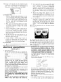
electrical
accessories
as listed
qn page
connections
POWER SUPPLY
1.
Motor
Specifications
The A-C motor
used in this saw is a capacitor
start,
non-reversible
type having the following
specifications:
Voltage
.............................
Amperes
..............................
Hertz (cycles)
.............................
120/240
11/5.5
60
Phase
................................
RPM .................................
Rotation
as viewed from saw blade end
4.
NOTE:
to just
....
This machine
must be grounded while
the operator
from electric shock.
THAT
HAVE
WEAR
including
metals,
YOUR
Single
3450
Clockwise
The operation
objects
being
of any power
tool
can result in foreign
thrown
into the eyes, which
can result in
severe eye damage.
Always
wear safety goggles complying
with ANSI
Z87.1 (shown on Package) before commencing
power tool operation.
Safety Goggles are available at Sears
retail or catalog stores.
HAZARD
OF
ELECTRICAL
SHOCK.
PARTICULARLY
WHEN
USED
IN
DAMP
LOCATIONS IN PROXIMITY
TO PLUMBING. IF AN
ELECTRICAL
SHOCK OCCURS THERE IS THE
POTENTIAL OF A SECONDARY HAZARD SUCH AS
YOUR HANDS CONTACTING THE SAWBLADE.
IF POWER CORD IS WORN OR CUT, OR DAMAGED
IN
ANY
WAY,
HAVE
IT
REPLACED
IMMEDIATELY.
If your unit is for use on less than 150 volts it has a
plug that looks like below.
3
P_Oh_[_
GROUNDING
piLJ(;
_ONG
P_OPE£L Y GROUt_D_D
3- PR©r_G CUlL ET
in use to protect
YOUR
OUTLET
IS
IT CHECKED
BY A
This power tool is equipped
with
a 3-conductor
cord
and grounding
type plug which has a grounding
prong,
Listed
by
Underwriters'
Laboratories.
The ground
conductor
has a green jacket and is attached to the tool
housing
at one end and to the ground prong in the
attachment
plug at the other end.
WARNING:
DO NOT PERMIT
FINGERS
TO TOUCH
THE
TERMINALS
OF PLUGS WHEN
INSTALLING
OR
REMOVING
THE
PLUG
TO OR
FROM
THE
OUTLET,
This plug requires
outlet as shown.
WARNING:
POWER
If the outlet you are planning
is of the two
prong
type
IF NOT PROPERLY
TOOL
CAN
INCUR
materials
Drill
Chuck:
Do not install or use any twist drill
larger than 1/2-inch
in dia., or longer than 7 inches
in length or ex.tending
more than 6 inches beyond
the chuck jaws. Do not install or use any reduced
shank drill except of the spade type (1 inch dia. or
smaller).
"Use for drilling
WOOD
and PLASTIC
only."
Do not overtighten
arbor nut. Use arbor wrenches
"snug" it.
CAUTION:
Your
saw is wired
for 120V
operation.
Connect
to a 120V,
15-Amp.
branch circuit and use a
15-Amp.
time-delay
fuse or circuit
breaker.
If the
motor
is used for
240V
operation,
connect
to a
15-Amp.
branch circuit and use a 15-Amp.
dual element
time-delay
fuse or circuit breaker.
IF YOU ARE NOT SURE
PROPERLY
GROUNDED,
QUALI FlED ELECTRICIAN.
"'tOP side"
you are
extend
(D) ACCESSORIES
recommended
is when
controt
4.
Use only
34.
exception
The
use of grinding
wheels,
abrasive
or cut-off
wheels, or wire wheels, can be dangerous and is not
recommended.
(Abrasive
or cut off wheels are used
NEVER
gang crosscut
- lining up more than one
workpiece
in froJ3t of the fence - stacked vertically,
or horizontally
outward
on the table - and then
pulling
saw thru:
the blade could pick up one or
more pieces and cause a binding
and possible iniury.
1.
The only
to saw many different
stone, and gla_s.)
carriage
is in this position.
Otherwise
the cutting
tool
ma_, climb
up on the workpiece
and be
propelled
toward you.
2.
saw when equipped
9vith a dado
head unless the mc)lding head
see listing
of recommended
dadoing or molding,
when the sawblade guaid must
be used. See detaited
instructions
that.accompaey_
the dado head, molding
head, and molding
head
guard.
3.
1.
Never operate this
head or molding
guard
is installed
GROUNDED
THIS
THE
POTENTIAL
a mating
3-conductor
grounded
to use for this power
DO NOT
REMOVE
type
tool
OR
z
electrical
ALTER
connections
-FHE
GROUNDING
PRONG
IN
MANNER.
Use an adapter as shown and always
the grounding
lug to known ground.
It it recommended
that you have a qualified
replace the TWO prong outlet with a properly
THREE
prong outlet.
ANY
(1) The orange-colored
wire
on number
6 terminal.
connect
(2) The brown-colored
w_re on number
5 terminal.
c
Use the
electrician
grounded
An adapter as shown below is available for connecting
plugs to 2 prong receptacles.
The green grounding
lug
extending
from
the adapter
must be connected
to a
permanent
ground
such as to a properly
grounded
outlet
box.
120V
power-cord
plug furnished
with
your
saw.
/'
["
/
:
\
":_ROU_DI_G LtJ(_
I
A _APTE_ /
\
3-PROb,h
PLLJG
r==_
t I: ll
\1;_
7
_
I ._
\
t'_'i/_'_+
/X'73:7":'-!I_'*:
"
_
R,
I
CON_ECT
II
D
Yb40,'¢N
--"_'_
TO
A
GPOtlN)
_ ERON--
Connections
a.
NOTE:
already
The adapter
illustrated
have a properly
grounded
ELECTRICAL
1,
Changing
a.
Motor
Heavy-duty
Either
an
circuit
serving
the saw motor.
voltage
supplied
(3) Low
which
b.
b.
ELECTRICAL
MADE
BY
A
Connections
(2)
i
by
company
the
cannot
power
8 terminal.
on number
7 terminal,
PLUG
BLADE t q, I
3 BLADE5
& RECEPTACLE
BOX
source,
NO
ADAPTER
AVAILABLE
fmlb
C.
d.
L
_ _
for 1207
a.
Remove
terminal
nameplate
board.
This
motor
1
b.
The w_res inside
shown
of the motor
motor
must
3-blade
receptacle.
SAFETY
should
PROTECTION
be blown
sawdust
out,
interference
or "'vacuumed",
with
normal
Your
saw
motor
is equipped
with
a manual reset,
thermal-overload
protector
designed to open the power-line
circuit when the motor temperature
exceeds a safe value.
\
i
from
a 240V,
TYPE PLUG
Make certain the receptacle
is connected
to a 240V
A-C power supply
through
a 240V
branch
circuit
having at least a 15-amp. capacity,
and protected
by
a 15-amp. time-delay
fuse or circuit breaker.
frequently
to prevent
motor ventilation.
A.C.
cover
saw into
IS
_OR
_'\
J
_
Plug your
MOTOR
x
,
Connections
be
Replace the 120V power-cord
plug with a (3-blade)
240V
plug, connecting
the power-cord
white
and
black
leads, respectively,
to the two "hot"
plug
blades -- and connecting
the power-cord
grounding
wire to the plug ground prong,
PROTECT_
2.
on number
wire
OUTLET
,i ,
, _
must
wire
correct.
_"....
/
i __
box
branch
NOTE:
/
colored
O_OUtqDING
LONGEST
OF
240V
terminal
GROdNDED
or an overloaded
Motor 'wiring connections
for 120V (as made at the
factory)
are
described
below.
Necessary
reconnections
for 240V operation
are also described
following.
Whenever
changing
connections
from
120V to 240V
or vice-versa, make certain that all
necessary
steps (including
proper
fusing of the
branch circuit) are completed.
//
motor
as follows:
operations.
undersized
the power
,f
A.C.
the
(2) The brown-colored
Under normal
home workshop
usage, and if proper
{full) voltage is supplied to the motor, your saw will
operate
efficiently
on 120V,
as connected
at the
factory
However,
ifanyofthe
following
conditions
exists, pt will be advisable for you to reconnect the
motor
for
240V
operation
to obtain
the
efficiency
and performance
for which your saw is
designed:
(1)
inside
(1) The orange
CONNECTIONS
IN
BE
for 2407
wires
connected
is for use only if you
2-prong receptacle.
WARNING:
CHANGES
CONNECTIONS
SHOULD
QUALIFIED
ELECTRICIAN.
The
to
expose
be connected
as
1.
If the pr(>tector opens the line and stops the saw motor,
_mmediately
press the
saw switch
to the "'OFF"
position,
and allow the motor to cool.
2
After
cooling
to a safe operating
temperature,
the
overload
protector
can be closed manually
by pushing
in the red button
on the top of the motor.
I1 the red
button
will not snap _nto place immediately,
the motor
is still to,) hot and must be allowed to cool for a while
longer.
In some cases this may take 20-30 minutes.
{An
audible
3.
4.
5.
cick
As soon
position
normally
position.
wil!
indicate
protector
6.
sizes and lengths
as the red button
will
snap into
running
the
saw
may
be started
and
operated
by pulling
out the saw switch to the "ON"
any extension
keep
this to
grounding
tvpe
the tools plug.
plugs
and
FUNCTION
Up to 100 feet
100 feet to 200 feet
200 feet to 400 feet
TABLE
3-pole
No.
No.
No.
OF CONTROLS
L ATCII
]STNG
cord will cause some loss of
a minimum
and to prevent
receptacles
table below to
extension
cord.
have 3 prong
which
accept
Wire Size Required
(American Wire Gauge Number)
240 Volt Lines
120 Volt Lines
Length of the
Conductor
#41TER SCALE
!I'4DICATO£
q£M
following.
NOTE:
For circuits
of greater length, the wire size must be
increased proportionately
in order to deliver ample voltage
to the saw motor.
Although
the motor
is designed
for operation
on the
voltage
and frequency
specified
on motor
nameplate,
normal
loads will be handled
safely on voltages
not
more than 10_&-above or below the nameplate
voltage.
Heavy loads, however,
require
that voltage
at motor
terminals
equals the voltage specified on nameplate.
PIVOT
the table
over heating and motor
burn out, use the
determine
the minimum
wire size (A.W.G.)
Use only
3 wire extension
cords
which
Frequent
opening of fuses or circuit breakers may result
if motor
is overloaded,
or if the motor circuit
is fused
differently
from
recommendations•
Overloading
can
occur if you feed to rapidly or if your saw is misaligned
so that [he blade heels. Do f_ot use a fuse of greater
capacity without
consulting
a qualified
electrician.
AND
with
WIRE SIZES
The use of
power.
To
is closed.)
LOCATION
Most
motor
troubles
may
be tracedi to loose or
incorrect
connections,
overloading,
reduced
input
voltage (such as small size wires in the supply circuit)
or
to an overly lung supply
circuit.
Always
check
the
connections,
the load and the supply ciri:0itTwheneverl
the motor
fails to perform
satisfactorily.
Check wire
t OCK
"/HEEL
CLA_4P
RIP
]CAt
I NDICArOR
14
12
8
No. 12
No.
8
No.
6
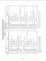
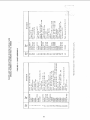
CONTENTS
Guarantee
....................................
General Safety Instructions
for Power Tools
.........
Additional
Safety Instructions
for Radial Saws
.......
Electrical
Connections
..........................
Assembly
and Alignment
........................
Unpacking
and Preassembly
.....................
Alignment
Procudure
.....................
assembly
2
2
3
5
Location
8
8
12
"....
and FunctioH
35
Parts
and alignment
.................................
FRAMING
C_
,_IING
A_CU
OF
_A
Screwdriver
MUST
Ci
%
_JAR5
EDCE
0xlectiu m)
SQUARE
ACY
BE TRUE
K[NC_
ACC[
DLISIDF
OF
BOARDS
_['
FRC:_JT
, [t_*OV_
R2,CY
Ct
OF
OUA_£
I,_3L[
D)
k
:-_:_
20
Repair
PqSIDE
:::::
...............
23
28
31
34
34
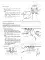
TOOLS NEEDED
@_
of Controls
Basic Saw Operations
..........................
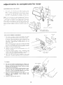
Adjustments
to Compensate
fol Wear . .............
Trouble
Shooting
............................
Maintenance
and Lubrication
................
Recommended
Accessories
......................
DRA¢¢
TABLE
LiC;H;
ALONG
LiNE
Ohd
THiS
EDC_
\
/
--_-
7/16-inch
wrench
9i16dnch
wrench
15/16
-inch
1/2-inch
wrenchwrench
,:#"2
Phillips
Screwdriver
E_
:
am
er
:1
SHOLII
square
D _E
SQb_RE
IN
WARNING:
A SOURCE
UNPLUGGED
THE SAW.
Key
Pencil
UNPACKING
AND
DO NOT CONNECT
THE POWER CORD TO
OF POWER.
THIS CORD
MUST
REMAIN
WHENEVER
YOU
ARE
WORKING
ON
113.199200
Radial Saw is shipped complete
but DOES NOT INCLUDE
Steel Legs.
in one
Model
carton
113.199250
Radial Saw is shipped
but INCLUDES
Steel Legs.
in one
Unpacking
and Checking
complete
before
discarding
any
2
3
the m_ssing parts are obtained
4
GAP
OR
_HEb,
FLIPPED
BE
O VE't LAP
OVE_
POSITION
of
SHOULD
Loose
5_JAP,
[N
E
LIo[rED
_40
HER
15
GAP
PO
OR
¢,_H [ N
FLIPPE_
OVER
I
OM
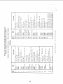
Parts
Qty.
Basic Saw assembly ....................
Rear table
...........................
1
1
Table spacer ..........................
Rip fence ..........................
Front table ...........................
Channel, Table Mtg .....................
"0woer's Manual" . ....................
1
1
1
2
1
.
Loose Parts Bag Part No. 63894
(containing the following; items):
Setscrew, cup pt. 1/4-20 × 3/8 ...........
Machine Screw, Pan Hd., 1/4-20 x 1"
. ....
Washer, Steel (Flat), 1;'/64 x 5/8 x 1/32"
..
Nut, "Tee" . .........................
Screw, Pan Hd. 1/4-20 x 1-3/4" . .........
Nut, Hex 1/4-20 ......................
Lockwasher, 1/4 .....................
Table Clamp .........................
*Loose Parts Bag Part No. 63796
(containing the following items):
Hex "L" Wrench, 1/8" . ................
Switch Key .........................
Lockwasher, 5/16"
. ..................
Washer, Flat11/32 x 7/8 x li16"
. .......
Set Screw, Cup Pt. 1/4-20 x 1"' . .........
Nut, Lock 5/16 18 ....................
Bolt, Sq. Hd. 5/16-18x3/4"
. ...........
Washer, 21/64 x 9/16 x 1/16"
. ..........
Nat, He;< 5/16-18 .....................
Loose Parts Bag Part [1o. 63898
Cap, Arm ...........................
Trim, Arm Cap .......................
Screw, Fiat Hd. Rec. Tvpe "T" 10 32 x 5/8
Screw, Pan Hd Rec. Type "T" 6-32 x 1/4 ..
If any parts are missing, do not attempt
to assemble
radial saw, plug in the power cord, or turn the switch
on until
correctly.
HER[
IS
DOTTED
Table
NO
(containing the following items):
Rip-Scale Indicator
...................
Twin Nut (for attaching rip scale indicator)
Machine Screw, Pan Hd., 6-32 x 1/2". .....
Hex "L"Wrench,
1/4 ..................
Hex '" L" Wrench, 3/16 ................
Elevation Crank Assembly .............
Arbor Wrench
.......................
Shaft Wrench ........................
Contents
for,
ION
THIS
Loose Parts Bag Part Ne. _3895
Separate all "loose"
parts from packaging materials and
check each item with "Table
of Loose Parts" to make
sure all items are accounted
packing material.
No.
1
2
3
4
5
6
7
PREASSEMBLY
Model
carton
1.
LINE
J
,
OVERLAP
Pliers
ALONG
_"
I!!
I,:_"!: __i-:: ::,._:. i ::_[!:
Framing
IGHT
[ABLE
[!i
_
d_.:__7__
_)?,A,'¢
and are installed
5
/
8
*This bag included in Loose Parts Bag No. 63895
2
2
4
1
1
!
1
1
1
4
5
I
1
4
4
2
1
1
4
4
1
2
4
2
4
1
1
3
2
EDGE
Thefollowingpartsareincluded
withModel113.199250.
Key
No.
Table
1
2
3
of
t.oose
Parts
Qty.
4
5
5
6
6
6
Leg .....................................
Stiffener, L.H .............................
Stiffener, R.H .............................
Loose Parts Bag Part No. 63752
(containing the following items):
- Screw, Truss Hd. 1/4-20 x 5/8 ..............
- Lockwasher, 1/4 External
.................
- Loekwasher, 5/16 External
................
- Nut, Hex 1/4-20 .........................
- Nut, Hex Jam 5/t6-18
....................
- Nut, Hex 1/2-13 .........................
4
4
4
40
40
4
40
4
8
7
8
9
- Foot, Leveling
..........................
- Screw, Hex Hd. 5/16-18 x 5/8 ..............
- Washer, 11/32 x 11/16 × 1/16 ..............
4
4
8
/
/
2
3
J
/
.j '_%.
_-j-o
4
5
6
9
8
17-3/4"
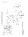
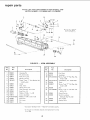
ASSEMBLING
STEEL
LEGS
o
NOTE:
Steel
From among
o
o
0
O
O
O
0
0
0
°n
0
Legs are furnished
with
Model 113.199250.
the loose parts, find the following
Hardware:
40
40
40
8
Truss Head Screws, 1/4 20 x 5/'8
Lockwashers,
1/4-External
Hex Nuts, 1/4-20
Hex Nuts. 1/2-13
4
Leveling
O
STIFFENER
STIFFENER
L.H.
R.H.
0
Feet
21-1/4"
Assemble
1.
2.
3.
the
Assemble
Legs as shown.
Two
(2) each of right
and left hand Stiffeners
to the
screws,
length shown
using I/4-20
Iockwashers
and hex nuts.
Attach
screws,
the four (4) legs to the
Iockwashers
and nuts.
x 5/8"
Stiffeners
truss
head
Ioool
o
O
using
1/4 20
These
levelers
adjustment.
are
not
intended
for
O
O
O
O
O
O
O
STIFFENER
L.H.
R.H,
3
2
1
3
/
height
CAUTION:
Leveling feet must be adjusted
so the saw does
not rock AND so that the arm slopes slightly
downward
to
the rear so the carriage wilt not roll forward
due to gravity.
°l
O
STIFFENER
Install leveling feet as shown. To level steel legs, loosen
nut on inside of leg and turn nut on outside to raise or
Iowe_ feet. Adjust
all four levelers if necessary, and then
tighten nuts on inside of leg.
NOTE:
o
O
/7
3
2
I./
2
/
1
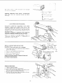
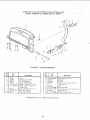
assembly
REMOVE
SKIDS
MOUNTING
1.
and
FROM
alignment
BASE
SAW
From
amonq
hardware:
the
loose
parts,
find
the
LEG
following
S[IF
ENER
L.F].
' TI_-F [ hJ B!
f(
l
4 Hex Head Screws, 5/16-18 x 5/8
4 Lockwasher,
5/16 in. External Type
8 Washers, 1!/32 ID
4 Hex Jam Nuts, 5/16-18
o_o
0
0
,k
0
ooo
x
2.
Place saw orl legs so that holes in bottom
with holes marked X in top of legs.
3.
Install
screws,
R.H.
x
of saw line up
washers and nuts as shown.
If you mount
th,_ saw on any other Craftsman
base or flat
bench, make sure Elevation
Crank has proper clearance
to
rotate. The saw must be boli:ed down. Position saw to slope
slightly
rearward, so when the carriage is installed it will not
roll forward
due to gravity,
x
o
000
oI
O
x
,IL
"v
ooo
i
HE,:
ATTACH
Install
FdLT
ELEVATION
setscrew
Be sure setscrew
CRANK.
h_to crank.
is tightened
Install
crank
on elevation
shaft.
on flat of shaft.
EL EVATIOIN
TL!RN
ELEVATE
Remove
ARM
shipping
TO ITS MAXIMUM
block
HEIGHT.
and discard.
lo
CRANK
CLOCKWISE)
..............
BE positivu
switch
is "OFF"
thfu out entre p_ocedure.
REMOVE
CARRIAGE
AND
TAG.
Read and
discarding.
and
power
cord
unplugged
STOP
SCREW,
LOCKWASHER
understand
warning
tag before
_
LOCK
HOLDING
HANDS,
ARM
BEFORE
CARRIAGE
CAREFULLY
_"--
HEX
'L' Wq.ENC_
SUPPLIED
PROCEEDING.
ASSEMBLY
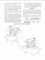
START
AND
WITH
SLIDE
BOTH
THE
CARRIAGE
ONTO THE TRACKS.
The assembly must be
held parallel
with_the
arm so that all four bearings slide
smoothly
onto the arm, preventing
any excessive strain on
bearings and track.
WARNING:
PREVENT
REINSTALL
CARRIAGE
CARRIAGE
STOP SCREW
FROM ROLLING
OFF ARM.
TO
Check
for
looseness
of
carriage
bearings.
Refer
"Adjusting
Carriage
Bearings"
in "Adjustments
Compensate
for Wear" Section.
to
to
ARM
-_._
INSTALL
ARM
WARNING:
CAP AND
ARM
Make certain
Insert finger
to the "ON"
2.
Place arm cap in position
3.
Attach
4.
Push switch
and install
REMOVE
screws.
VIEW
OF
SHOWING
UNDERSIDE
FROM
BOTTOM
SIDE
V
BLADE.
Tighten
carriage
2.
3.
Loosen guard clamp screw, remove guard.
Motor
shaft has left hand threads.
Hold
and rotate
MOTOR
OF
SCREWS
may be necessary.
SAW
OF
LOCATION
SHIPPING
1.
4.
end out
position.
REMOVE
SHIPPING
SCREWS
OF MOTOR
AND DISCARD.
Use of pliers
lever and pull
using screws.
to "OFF"
SCREW
cord is unplugged.
under end of switch
position.
arm cap trim
CAP
\
CAP TRIM
power
1.
_
arbor
lock
knob.
wrench
down
shaft
PULL
wrench
TO
(clockwise).
Remove
shaft nut, outer collar, saw blade,
collar. Set aside and out of the way.
and
inner
BLADE
ROTATION
11
DOWN
LOOSEN
TWO
SCREW
assembly
and
ALIGNMENT
alignment
PROCEDURE
IMPORTANT:
IN ORDER TO OBTAIN MAXIMUM
CUTTING
ACCURACY,
THE FOLLOWING
SIX STEPS
MUST
BE
CAREFULLY
FOLLOWED.
BECOME
THOROUGHLY
FAMILIAR
WITH
THESE STEPS SO THAT YOU CAN AL WA YS
MAINTAIN
YOUR
SAW
IN
PROPER
ALIGNMENT.
THE ACCURACY
OF EACH
ADJUSTMENT
IS ALWAYS
DEPENDENT
UPON THE A CCURAC Y OF THE PRECEDING
ADJUSTMENT.
After
follovving
the
6 step
assembly
procedure
and the Basic Saw operation
Trouble
Shooting
section
if any difficulty
when performing
any sawing operation.
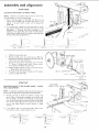
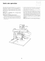
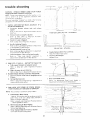
STEP
ATTACHING
1.
2.
AND
LOCKWABHER
FLAT
/
WASHER
FRO
[.EVELING
TABLE
will
MOUi_I"
Release
bevel
Unlock
lock
and
hold
as
lever,
arm
shown.
(approximately
move
50 °
position
carriage
control
miter).
standard,
_otation
stops
have
been
of the radial
arm.
arbor
shaft
and
Carefully
the
end
reasons
wrench
mounting
lower
the
of
shaft
Looser]
over
in
is just
lever
saw
lever
m
index
stop
carriage
Jock
knob
hand
touching
wrench
should
slide
back
and
resistance.
Ti _hten screw
"A".
channel.
with
to
the
prevent
between
end
of
act as a feeler
elevation
crank
the
arbor
forth
NOTE:
Do not change
this elevation
left
and
right
hand
table
support
with
setting
channels
of
release
left
provided
to
with
end
against
left
U,_LOCK
to the
blade
accordance
handle
channel
motor
index
arm
directly
For
the
safety
bevel
positido
Position
NOTE:
Slide
USING
HOLES
MOUNTING
Attach
table
mounting
support
channels
with
four
square head 5/16 18 x 3/4 screws, Iockwashers
and flat
washers and luts. POStTION
SCREWS IN CENTER
OF
CHANNEL
SLOTS,
finger tight to permit
channels to
"sip"
against the base when leveling.
and
RAILS
THESE
_'_T
CHANNELS.
position
4.
NG
CHANNEL
ONE
left
and rotate
the
motor
to
shaft down.
Lock
bevel
lock.
3.
_4OUNTI
\
and
a/ignmer_t
section
refer to
_s experienced
NOTE:
The following
adjustment,
performed
properly,
result in the work table being parallel to the arm.
SUPPORT
[ABLE
SUPPORT
wrench.
only
until
have
UL
360 °
motor
gauge.
until
The
slight
both
been
ARBOR
WRENCH
adjusted.
SCREW
5.
Move
arm and carriage
to
support
in the same manner.
6.
Move arm and carriage
to right hand support
channel
and level in the same manner you adjusted the left hand
support
channel.
7.
Recheck
both
support
channels
tightening
_,crews did not affect
adjustment
8.
Elevate
provide
saw and place motor
clearance for installation
screw
to
the
"B"
and
"_, "
tighten
make sure that
accuracy
of the
in vertical
posit_on
to
of front (work) table.
tABLE
MOUNTINC
SUPPORT
(LEFT
SCRERV "B
12
SCREW
'_,"
CliANF4EL
HAND)
FqONT
/_\\(IN
dPSID£
HOL_
,iOLD
r-b_UT
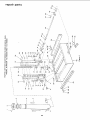
INSTALLATION
OF FRONT
(WORK)
TABLE.
1.
Place front table board upside down on a workbench
of
on the floor.
Drive
T-nqt
into the bole that is not
counterbored.
2.
Align the counterbored
holes with
matching
holes in
support
channels.
Install
the
five 17/64
inch flat
washers,
and four _/_- 20 x 1 inch Pan-Head machine
screws. JList barely start the cup point set screw and the
one (1) _A 20 x 1-3/4 inch Pan Head machine screw in
table center holes.
3.
Install
four
one
% Ioekwasher
(4) screws
and
in the support
Hex Nut
channels
on each of the
and tighten.
4.
Lay the rear table board on edge across the front table
to serve as a straightedge.
Sight under this straightedge
to determine
whether
the front table board is high or
low at its center.
5.
If the frorrt
table is high at center, first tighten
the
center (Y_
20 x 1-3/4 inch) hold down screw until the
table is level
then tighten the leveling screw until this
screw issrug.
If table is low at center,
until the table is level
screw.
first tighter] the leveling
then tighten
the hold
If table is not high o_ low, tighten
center hold down screw snug.
leveling
screw
down
screw
arrd
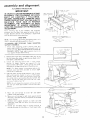
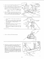
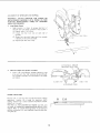
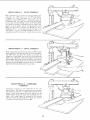
STEP TWO
ADJUSTING
COLUMN
TUBE
NOTE:
following
adjustment
The
IN COLUMN
is very
SUPPORT
CRITICAL.
All
future
alignment
procedures
rely on this adjustment
being
performed
correctly.
ALL
LOOSENESS
MUST
BE
REMOVED.
1.
Index
and lock arm at 0 ° Miter.
While
other
holding
the arm with one hand, hold fingers of
hand as shown, between column tube and column
support.
Apply
gentle
side pressure
to the arm m
opposing
directions.
Any side to side or rotational
rrrovemen[
(indicated
by arrow) can be felt with finger.
If
Ioose_ss
r_rquired.
exists
the
following
adjustments
are
13
TABLE
DO,Vi_
FOR
POSITION)
IA_LE
DOWN
(IYPIC_L)
SCRE?¢S
BOTTOM
T-NUT
\
SIDE
0 _ 1ABL_
assembly
2.
Loosen
(2) v4
rear of the column
3.
and alignment
20 Gib set screws on the left side at the
support.
Elevate,
and then lower the Arm:
{a} if the column
binds and elevation
-is difficult
loosen two 5/16
18
plated bolts on front side of the column
support
until
you
achieve
smooth
but firm
elevation.
(b) If the
column
moves side-to-side
within
the column support,
tighten
the two 5/16 - 18 plated bolts until movement
disappears
elevation should be smooth and firm.
4.
Now tighten
the 12} 'A
noticeable
rotational
play
and Column Support.
5.
Recheck
elevation
B IGHT
PLATE0
/
20 Gib set sclews until no
exists between Column Tube
and re adjust
i
J
I
I
if necessary.
I
BLADE
ROTATION
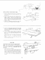
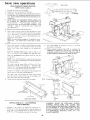
STEP THREE
SQUARING
TRAVELS
CROSS
CUT
TRAVEL
IN A STRAIGHT
LINE).
(CARRIAGE
1
Index but do not
lock arm at 0 ° miter.
2.
Install saw blade
threads.
as shown.
NOTE:
to just
Do not overtighten
"snug"
arbor
Motor
nut.
shaft
has left
Use the arbor
hand
wrench
it.
A_BOR N JT -_
14
_NN_RCOtLAR
3.
Lower a'm until saw blade just clears the front
Lock th_ yoke loci< handle ind bevel lock lever.
4.
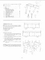
Place
a
framing
square
on
the
table
table.
as shown
and
position
the blade and square until the leg of the square
just contacts a tooth of the blade. Mark this tooth.
NOTE:
5.
The framing
"true"
Alignment"
method.
When the carriage
the marked
tooth
(o_ combination)
see
start
of
section
on p.
moves into
adjustments
Loosen (3) 3/8
of aHqn_
h.
Mow_ the arm in proper direction
to make marked
tooth folfo_,
edge of square when the saw blade is
moved along arm in a "cross cut" manner.
Lock arm latch.
d.
16 set screws
in arm latch
RETIGHTEN
{3) setscrews in arm latch
possible and recheck "cross cut" travel,
NOTE:
This
simultaneously
positions.
Set mitur
indicator
BEVEL
squaring
of
set BOTH
TO0
TH
._
at rear
as tight
HEX
"L"
as
\
as shown.
CLAMP
6.
Position
the rip (guide)
fence, spacer board and
table board behind the front table board as shown.
7.
Install the two table clamps in the holes provided
for
them
at the
rear of the table
mounting
support
channels
and tighten them securely.
WRENCH
(SUPPLIED)
the cross cut travel will
of the 45 ° miter index
on 0 ° position
LOCK
LEVER
square or away
are required:
a.
c.
YOKE
LOCK
HANDI
E
is moved back and forth on the arm,
should just touch the square at al!
points.
If marked
tooth
from square the following
e.
square must be
"Assembly
and
8 for
checking
rear
NOTE:
The life of your saw table will be lengthened
considerably
if you will cover the front
table with a
fitted
piece of % inch plywood.
This should be tacked
in place for easy replacement.
Use of such a cover will
allow you to do all cutting
into the cover, rather than
your table top.
WASHEP
REAR TAB
RIP
SPACER
FRONT
15
TABLE
FENCE
assembly
and alignment
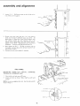
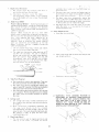
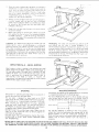
STEP FOUR
SQUARING
SAW BLADE
TO (WORK)
TABLE
NOTE:
If alignment
procedure step one was not
this adjustment
can not be accomplished.
1.
performed,
Place a framing
square on the table with the short leg
against the saw blade. Do not allow the square to rest
against a "set out"
tooth;
it must rest flat against the
blade side.
2.
RIP
FENCE
If the saw blade is square with the table top (no visible
gap appears between
the saw blade and square) and no
adjustment
is required.
Set bevel indicator
to 0 °
reading.
If the square does not touch the saw blade as
shown (with square leg held firm against the table top),
perform
the following
adjustments:
T
_OUA_E
•
_1^_
r_ U
_
]
'A/_O
WR O N O
t'q O
a.
Tighten
b.
Remove
handle
cover by removing
two
Head Screws. Remove handle by removing
socket head screw and Iockwasher.
#t0
Pan
5/16- !8
Loosen
1/4"
c.
carriage
!
1
j!
TABLE
socket
head screws
with
Rotate
motor
while
holding
saw blade and table top.
d.
Slightly
tighten
• . . Now tighten
e.
Reinstall
f.
Loosen
RIGHT
lock knob.
the four
"L'"
Wrench.
firmly
against
SQUARE
Hex
square
each of the four screws and recheck
each screw tight.
handle
carriage
and adjust
indicator
on 0 ° reading.
lock knob.
NO.
10
PAN
SCREW
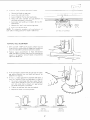
STEP FIVE
SQUARING
BLADE
HEEL ADJUSTMENT.
TO
RIP (GUIDE)
FENCE
-
LEFT HAND
CARRIAGE
BLADE
NOTE:
If alignment
procedure steps two and four were not
performed,
this alignment
step cannot be accomplished.
Position
carriage
as shown
and tighten
carriage
lock
knob.
Place a framing
square against the rip fence and
the saw blade, as shown. The long leg of the square
must be held firmly
against both the fence and the table
top, and the short leg must not touch any of the teeth
on the saw blade. Check at several points
of blade
rotation.
2.
If
two
the
square
points
does
not
as shown,
touch
a heel
the
blade
condition
at both
of
RIP FENCE
the
exists.
FENCE
1
LI
_20
NG
16
HD
3.
To cotrec_
"heel"
proceed
Remove
b.
Loos_n
the yoke
lock
c,
Loosen
(slightly)
the t_'Jo hex-head
d.
Rotate
the yoke assembly
until
saw bade and square is eliminated.
e.
Lock yoke lock
head screws.
f.
Recheck
Loos[,n
hand carriage
as follows:
a.
g.
left
cflndit_on
handle
for "heel"
carriage
cover.
HIx
handle.
and
gap between
retighten
and install
carriage
the two
HEEL
5CR[vVS
the
hex-
cover.
lock knob.
NOTE:
Tbs alignment
procedure
will simultaneously
both yoke indexing
positions
for blade in and out rip.
VERTICAL
tE,\D
screws.
set
LEFT SIDE C'F ICA_RIAC2[
-ADJUSTMENT
1.
With smt,,blade in 90 ° cutoff
position,
elevate saw and
rotate motor to vertical position
(Blade Horizontal)
and
check fol heel. Make sure bevel lock lever is locked.
2.
Position
square
perpendicular
to fence and between
blade and table, as shown lower arm. Do not allow the
square to rest against a "set-out"
tooth, it must rest flat
against the blade side.
If the saw blade is parallel
with
gap appears
between
adjustment
is required.
saw
the
the table top
blade
and
(no visible
square),
no
If there i,_ a visibie gap between saw blade and square, a
bevel heel condition
exists and adjustment
_s required.
a.
To correct,
unlock
bevel lock lever, loosen the rear
motor
mount 3/8-16 nut until you can rotate Cam,
and _hen rotate
Cam as shown until gap between
saw, blade and square is eliminated.
b.
Tighten
c.
Reposition
nut and bevel
motor
\
lock lever and recheck.
in crosscut
position.
SOUAR_\
'J
TABLE
RIGHT
1
VlR 0 N G
WRONG
(ILJRt_ C&M
C() L,I NTER CL ()CK t_'l S_}
17
{TURN
CAM
CLOCK'HISE)
1
assembly
and alignment
SCREW
STEP
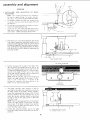
INSTALLING
INDICATORS.
AND
SIX
ADJUSTING
RIP
SCALE
NOTE:
The rip scales and pointers
are ntended
to
be used for quick
settings.
For greater accuracy,
take direct measurement
between
blade and fence.
a
Pre-assemble
not remove
carriage
b.
Tilt
ndicator
the two
cow,r.
carriage
Tighten
and twirl nut, loosen but do
screws which attach left hand
cover and install
carriage
attaching
rip indicator
as shown.
screws.
TWIN
c.
Loosen
but do not remove carnage
lock knob in
right hand carriage cover. Install rip indicator
in the
same manner. Tighten carriage attaching
screws.
d
With
front
thefeqce
in its normal
table),
loosen the yoke
NLJF
position
(next to the
lock handle,
pull on
yoke pivot latch knob and rotate the yoke as shown
to index the yoke 90 ° from the cross cut position
This will locate the saw blade between
the motor
and the fence
Lock
yoke lock handle
the
yoke
by tightening
the
FENCE
/
I
REAR TABLE
TABLE
SPACER
the "0"
mark,
then tighten
position,
the lower
port_on
scale would be used.
of
the
CARRIAGE
LOCK
f.
The blade
hand side
the same
except the
measured
blade, the
to read 2
"Out- Rip"
NOTE:
"Out-Rip"
scale indicator
on the left
of the radial arm is adjusted in essentiall V
rrlanner as the blade "In Rip" indicator,
blade should be as shown. With 2 inches
between
the fence and the face of saw
_ip-scale indicator
should be positioned
inches on the upper portion
of the blade
scale.
With
the saw blade and fence
INDICATOR
-I°
the screws.
NOTE: With the saw blade and fence in the position
shown,
the upper
portion
of the blade "In-Rip"
scale
is used.
If the fence
is redocated
at the
extreme
rear
blade "'ln-R,p'"
KNOB
j
L
in the position
shown,
the upper portion
of the blade "Out-Rip"
scale is used. If the fence is moved to rear position
(at the rear of rear table) the lower portion
of the
blade "Out Rip" scale is used.
g.
J
BOARD
RIP SCALE
Position
carriage until the edge of the blade, when
spun by hand, just touches the front face of the
fence. The rip-scale indicator
(on the right hand side
of radial arm) should now read "'0"" inches on upper
portion
of the blade "In-Rip'"
scale. If not, loosen
screws and shift the indicator
until it is aligned with
DNT TABLE
Loosen
the yoke lock handle,
pull on the yoke
pivot latch knob and return
the blade to the 90 °
position.
2"
TO
18
MEASURED
NEAREST
_ROM
BLADE
FENCE
TOOTH
!
J
i
ALIGNMENT
OF SPREADER
FOR
jL
•
RIPPING.
WARNING
NEVER
POSITION
THE
GUARD
OR
ANTI KICKBACK
ASSEMBLY
WITH
POWER
ON; NOR
POSITION
ANTIKICKBACK
PAWLS
BY
GRASPING
PAWLS OR SPREADER.
2.
Install
a
Blade
Guard.
Sight (visually)
to check
for proper alignment
of
spreader with saw blade as shown. If the spreader is
not aligned, adjust it as follows:
(1)
loosen
two
hex
nuts,
one
on
each
side
of
spreader.
(2)
Rotate hex nuts with
is directly
in line with
(3) T_ghten
both
fingers until
saw blade.
the spreader
HEX
hex nuts firmly.
NUT_i
ANTIKICK
BACK,
ADJUSTING
3.
Cheek and Adjust
a,
the spreader
SPREADER
I/riNG
SCREW
as follows:
Loosen
the antikickback
spreader adjusting
wing
screw and with the "tab"
position
the antikickback
and spreader assembly near the bottom
of the blade
and tighten.
OUISIDE
FENCE
VIEW
_
ANTIKICKBACK
/_V_"
PAWLS
INSID_
VIEW
LOCATIONS
Position
(A) is used for most cutoff
and narrow
ripping
operations.
Position
(B)
is used for
maximum
width
ripping.
Position
(C) is used to achieve maximum
crosscut
capacity in thin work.
B
CA
q
,----fi-fl
Now that you have assembled and aligned your saw, you
are ready to proceed with operating
controls section of this
manual.
Refer to trouble
shooting
section if saw does not
perform
satisfactorily
or am/ problems
should surface after
using the saw
19
J
location
The
and function
versatihty
controls,
Learn
to
starting
of
and
use
the
Radial
Saw
is
clue,
M
part,
to
_ts
, I
these are the keys to its successful
operation.
the controls
for all operations
before
actually
a
to saw.
A sedes
of
six
diagrams
is located
arm. Thtse
designate
the
set-ups
and
operating
familiar
that
of controls
with
folk)w,
these
before
on
the
controls
that
procedures.
diagrams
and
operating
the
your
top
must
You
surface
be used
should
operating
of the
ir_ basic
become
CUT
CARRIAGB
LOCK
I
instructions
saw.
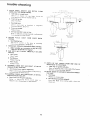
MITER SCALE
INDICATOR
2
ARM CONTROL
BEVEL INDEX
RIP SCALE
DEPTH
OF
(ELEVATION)
i
LEV_.R
LEVER
ANGLE
INDICATOR,
OF
CUT
I
IMITEB]
BLADE
ANGLE
i
b
3
O N-OFF
YOKE
PIVOT LATCH
SWITCH
WITit
KEY
ARM
USTING
LOCK
WHEEL
BLE CLAMP
c_
o
GUARD
8
BLADE GUARD AND
ANTI KICKBACKiSPR
EADE R
A£SEMBLY
CLAMP
SCR EW
RIP SCALE
INDICATOR
ELEVATION
CRANK
1
\\
4
CARRIAGE
OCK KNOB
3
LOCK
HANDLE
7
ACCESSORY
SHAFT
ANTIKICKBACK,,
SPREADER
ADJUSTING
SING
SCREW
BEVEL INDEX
INDICATOR
_o
5
BEVEL LOCK
LEVER
2O
(BEVELI
1.
2.
Depth
of Cut (Elevation)
a
The diagram
shows the eevation
crank
used to raise and [owe_ the saw blade
b.
CIo(kwise
rotation
ra ges the
blade
. . .
couuterc]ockwise
rotatior
lowers it. ©he complete
turn of the handle wil] _aise or Iowe_ the saw blade
1/16 inch.
Angle
which
is
arm
control
lever
the arm for Left and
b.
The
and
lever
pulling
arm control
With
arm
control
locks,
Right
unlocks
Miter
6.
and
The bevel lock lever locks the motor
when the motor
_s in any positon
release and push tO lock.
Power
Switch
Insert
key
UNLOCK
/'_,,
5.
IND£X
"-,.
Insert finger under
out, to turn switch
....-.
end of
or'..
switch
--
ill
end
_\
switch
off.
--._
yoke
pivot
this
forward
to release
The,/are:
handle.
pin.
The .,,oke lock handle
locks the yoke to the carriage
in any position.
Pull the handle
forward
to release
the yoke:
push
the handle
rearward
to secure
the yoke
d.
Lock
a.
The -arriage
lock knob is rotated
clockwise
to lock
the carriage on the radal arm, and counterclockwise
to re ease it.
b.
When
perform
ng crosscutting
operations
the
cart
_age
lock
knob
must
be
rotated
counterclockwise
until the carriage is free to travel
along the arm. This knob should be tightened
until
the operator
is read,/ to grasp the bevel index
i_andie and make a cut.
WARNING:
THIS
LOCKING
FEATURE
IS
PROVIDED
TO
PREVENT
UNAUTHORIZED
USE OF YOUR
SAW. ALWAYS
REMOVE
THE
KEY
AND
KEEP
IT IN A SAFE
PLACE.
TO
REMOVE
KEY,
HOLD
THUMB
ON
END OF
LEVER
TO KEEP SWITCH
IN "OFF"
POSITION
AND
(Bevel)
contro8
of the
lever and pull
.-"
Push lever m to turn
indexes
the
spdng-loaded
Angle
x. \
\
b.
nJ
yoke
pivot
latch
automatically
at each 90 c position.
Pull the
The two
inde_Jmg
_ ._-X-T
/j
The
yoke
a
lock.
<;
I! I
RELEASE
b.
Blade
into switch
indexes
Two controB
are used in this operation.
the yoke pivot latch and the yoke lock
Carriage
to the yoke
Pull ]ever to
and Key
(Nipping}
tatctn
and
cuts.
a.
c.
4.
Pivot
JGc,k;l_ver
,
The bevel index ]ever automatically
indexes
the
motor
at 0 °, 45 ° and 90 ° Move bevel index lever
a.
lever to index release position.
lever
released
the arm will
u
Yoke
beve
c.
automatically
index at 0 ° and 45 ° Left or Right.
Aft(r
positiomng
arm to the desired miter angle,
push arm control
lever to locked position•
3.
are:
The bevel ;nd___xscale indicates the angular pOS!t_on
of the motor w_th respect to horizdntaf,
fom 0 ° to
90 ° in either vertical position.
_ ....................
_,
d.
radial
arm has positive
index pos_tLons at 0 °
4E ° Left and Right
The arm is rotated
by
L,'DCK
angle,
to the left while positioning
the blade, then re!ease
*
r poslton
it. At any (),he
it does not engage.
Examph,
When
moving
the arm to a miter
index
position
move _t slightly
past the desired index posit_on,
then ret 4rn to the index position
carefully
to index and
lock,
Yoke
indexng
and
bevel
indexing
can be
accomphshed
_rl a smiar
manner,
l-his
indexing
techrfiq(m
tends to neutralize
any stresses impaired
upon
saw components
and contributes
to the high
degree of accuracy
the saw is capable of producing
when operated expertly.
]he
(bew_)
bevel-index
b.
of Cut (Miter)
Proper
Indexing
Method
Experenced
operators
of
woodworking
equipment,
such as this Craftsman
Radial
Saw, acquire
the habit
of ndexing
in one direction
only, vdqenever a newsettmg
s made m preparabon
for
a differ{ nt operation.
a.
saw blade
userJ in angular
positiomng
and
motor,
to provide
the desired
21
PULL
KEY
STRAIGHT
OUT.
location and function of controls
WARNING:
FOR YOUR
OWN SAFETY
ALWAYS
LOCK
THE SWITCH
"OFF"
WHEN
SAW
IS NOT IN USE.
REMOVE
KEY AND
KEEP IT IN A SAFE PLACE
. . .
ALSO
IN THE
EVENT
OF A POWER
FAILURE
(ALL
YOUR
LIGHTS
GO OUT) TURN
SWITCH
OFF, LOCK IT
AND
REMOVE
THE KEY THIS WILL PREVENT
THE
SAW FROM STARTING
UP AGAIN WHEN THE POWER
COMES
BACK ON.
7. Accessory
AN TI K]CKBACKiSPREADE
WING SCREW
GUARD CLAMP
SCREW
accessory
shaft, N EVER operate
the saw with
tools (including
sanding accessories)
installed
ends of the saw arbor.
Blade Guard 8= Antikickback/Spreader
Positioning
for Ripping.
WARNING:
NEVER
POSITION
ANTIKICKBACKiSPREADER
THE
SAW
RUNNIN6.
ANTIKICKBACK/SPREADER
GRASPING
THE PAWLS
TAB LOCATED
ON THE
A
_ TAB
Shaft
tmj
Use only the following recommended
accessories:
Drill
chuck, Sanding
drum, and Router adapter.
CAUTION:
The sawblade,
dado, or cutting
tool must
be removed
from
the saw arbor
before
using
the
8.
R
THE
WORKP]ECE
ANTIKICKBACK
--
GUARD
OR
PAWLS
\
WORKPIECE
ANIIKICKBACK
cutting
on both
Assembly
\
BAR
Make sure by trial -- without
saw running
-- before
starting the cut that the antikickback
pawls will stop a
kickback
once
it has
started.
Insert
workpiece
alongside
spreader
under
outer
set of pawls
by
approaching
pawls
in the feed
direction.
Push
workpiece
sharply
in the direction
of a kickback
(opposite
to direction
of feed). Readjust Pawls if they
do not stop the kickback
motion
by biting
into the
workpiece.
ASSEMBLY
WITH
NEVER
POSITION
THE
ASSEMBLY
BY
OR SPREADER;
USE THE
ANTIKICKBACK
BAR.
These
adjustments
Antikickback
The Blade Guard is positioned
by loosening
the guard
clamp
screw
and rotating
the guard
so that the
"nose"
just clears the workpiece
as shown.
1. Stop
a kickback
when
properly
made
will:
Pawls
if generated.
Spreader
GUARD
WORKPIECE
MINIMUM
1,
CLAMP
2. Prevent
/
SCREW
OUTFEED
------
--_P-
NOSE OF
GUARD
INFEED
DIREOTIOP_
This adjustment
is necessary
3) Minimize
operator.
sawdust
from being lifted from the
thus minimizing
lifting or
with
thin
and!or
light
from
being
thrown
toward
feed".
3,
antikickback
during
ripping
accommodate
ripped.
and
spreader
operations
the thickness
and
of
assembly
the
approximately
wing screw.
the position
shown
ANTI
Tighten
BAR
SPREADER
/
/
ANTIKICKBACK
'
is adjustable
to
the board
being
above.
KICKBACK
F
/
is used
The
antikickback
and
spreader
assembly
is
positioned
by loosening
the wing screw and with the
tab
provided,
positioning
the
antikickback
and
spreader
assembly
until
the
pawl
assumes
feed"
kerr
is
Act as a partial guard regarding
accidental
contact with
the sawblade
at the outfeed
side when ripping, and the
leading edge when crosscutting."
4) Minimize
the possibility
of a thin pusher
board
from riding up on top of the workpiece
leading to
loss of control
of the workpiece.
B. The
"Wrong-way
the
"Wrong-way
feed"
differs
from
"kickback."
A
"kickback"
is generated
by the sides (one or both) of the
teeth,
because
of binding
between
the fence (heel),
pinching of the sides of the sawblade
(failure
to use
spreader),
a dull blade, and/or
inadequate
set of teeth of
sawblade.
to:
1) Protect the operator
from accidentally
contacting
the sawblade
from the "infeed'"
direction.
2) Prevent the workpiece
table by the sawblade
fluttering
(particularly
workpieces)
"wrong-way
by preventing
feeding
the workpiece
- when the sawblade
is in a rip
position
- into the out feed side of the cutting
tool
(sawblade.
dado,
molding
head,
etc.,),
the
side
containing
the antikickback/spreader.
This
can
be
extremely
hazardous
because
the sawblade
may grab
the workpiece
and throw it violently
toward the nose of
the guard (infeed side of the tool). See DANGER label on
the outfeed side of the guard just below the dust elbow.
1
_
Reduce possibility
of kickback
from closing on the sawblade.
PAWL
/
DIRECTION
FEED
D!RECTION
the
22
OF KICKBACK
ANTIKICKBACK
PAWL POSITION
OF
basic saw operation
i
Basic saw operations
are summarized
into s_x categories,
explained
and illustrated
in the following
paragraphs.
A
book
entitled
"Power
Tool Know
How Radial
Saw" is
available
at your nearest
Store. This book contains
the radial saw
Sears Retail
considerable
NOTE:
Refer to paragraphs
FUNCTION
OF
CONTROLS"
description
of controls
Cutting
a kerf
in the table
under
for
boards
3.
4. Insert the yellow
key into switch
and. while
Yoke handle,
turn the switch
on.
Store or Catalog
data applicable
to
'LOCATION
illustralions
holding
the
5. With the motor on, iower the sawblade
to where it just
cuts into the table approximately
1/32 to 1/16 inch
deep While
holding
the Yoke handle
and with motor
still on loosen the carriage
lock knob and then pull the
motor forward
andou[tothefrontstoponthearm
This
will allow the blade to cut through
the fence and to cuta
shallow
kerf in the table 1/32
to 1/16 inch deep to
provide
for the blade cutting
completely
through
the
workp_ece
AND
and
and fence.
1 Elevate arm so that the blade clears the top of the fence
and then push the motor to its most rearward
position
2
Lock the carriage
lock knob. Plug saw into a grounded
outlet.
(See section
titled, "electrical
connections").
Lower
the arm so that the blade just clears the rear
table. Note: the rear tableshould
be at the same level as
the front taole.
NOTE:
making
23
A kerf will have to be cut into the table prior to
miter, bevel, or rip cuts using this procedure.
basic
saw
operations
REQUIREMENTS
Board
laying
FOR CROSSCUT
posibon
(stationary)
fiat on table top.
against
(OPERATIONS
rip
fence
1 THROUGH
and
4)
1.
Arbor
nut must be tight
in horizontal
position.
2.
Arm
3.
Adjust the antikickback
assembly so the pawls just clear
the workpiece
or the fence, whichever
is higher.
4.
Work must be held firmly
against table and fence. For
workpieces
thicker
than
the fence is high, install
a
higher
fence
(at least workpiece
thickness).
Always
place the fence in the most forward
position
(farthest
from
the
column
support)
compatible
with
the
workpiece
oeing p_ocessed
and the operation
being
performed.
With the carriage fully retracted,
the blade
must
not contact"the
workpiece
whet] placed against
the fence, w,ithin the stated capacities of your saw.
5.
Blade should
6.
Hands
7.
Yoke
8.
Bevel index
9.
Blade should cut into
more than 1/32 inch.
!0.
Pull the saw ,forward
just far enough
to sever the
lumber.
It is dangerous
if the blade has been pulled too
far out beyond
the piece being cut. When it is returned
it can pick up the right hand piece and throw it over the
fence.
contro!
lever must
and saw blade
(guide)
be in locked
be sharp and correctly
handle
must
installed
position.
set.
must be kept we!1 away from
lock
guard
be in locked
saw blade
position.
(SEE
PROPER
ITEM "10"
AT
LEFT)
IMPROPER
ITEM "10AT
LEFT)
lever must be locked.
11. For operations
No.
instructions
under
"'Blade Angle".
OPERATION
the
table
or plywood
3 and No. 4, observe
paragraph
"Operating
cover
not
additional
Controls'"
No. 1 - CROSSCUT
Crosscutting
is the process of sawing the workpiece
by
pulling
the saw blade through
it and using the fence as a
support
for the edge of the workpiece.
Never crosscut
free hand.
WARNING:
BEFORE
CROSSCUTTING,
MAKE
SURE
THE ARM
CONTROL
LEVER,
BEVEL
LOCK
LEVER
AND YOKE LOCK HANDLE
ARE ALL LOCKED,
NEVER
USE A LENGTH
STOP OR A FIXED
GUIDE
ON THE
FREE END
OR EDGE
OF A WORKPIECE.
DO NOT
CROSSCUT
WORKPIEOES
THAT
PLACE
YOUR
HANDS
CLOSE
TO THE PATH OF THE SAW BLADE.
WHEN
MORE
EXPERIENCE
IS GAINED
BY USING
THE
SAW,
IT WILL
BE NOTICED,
THAT
WHEN
PULLING
THE
SAW
TOWARD
YOU
DURING
CROSSCUTTING,
THE
BLADE
TENDS
TO
FEED
ITSELF
THROUGH
THE
WORK
DUE
TO
THE
ROTATION
OF THE BLADE AND THE DIRECTION
OF
THE FEED.
THEREFORE,
YOU
SHOULD
DEVELOP
THE
HABIT
OF
HOLDING
YOUR
RIGHT
ARM
STRAIGHT
FROM THE SHOULDER
TO THE WRIST
(SEE
REPETITIVE
CROSSCUTTING
Clamp a "C'" clamp (min. 6 inch) using a wood block on
each side of the arm. This will
limit
the carriage travel
beyond
the position
necessary
to complete
the crosscut
operat Ion.
24
OPERA]ION
No. 2 -- MITER
CROSSCUT
Miter crosscutt_t_g
s the process of sawing a board at any
angle other than a 90 ° (square} cut. The 45 ° miter _ngle is
a popular
one, since two
boards
cut to 45 ° can be
assembled to form a 90 ° corner for producing
a square or
rectangular
frame. The radial arm _sset to the desired angle
of cut; yoke and bevel settings indexed at 0 ° (and locked)
as in square crosscutting.
The board being cut is held firmly
against the fer_ce (guide) and the carriage pulled forward
along
the radial arm to perform
the desired cut. As in
"Operation
No. 1", the carriage should be returned
to full
rear position
and the saw blade allowed
to come to a
complete
stop before removing
the boards from saw table.
OPERATION
Bevel crosscutting
across the board
than 90 ° to the
indexed at 0 ° and
No. 3 - BEVEL
CROSSCUT
is the process of sawing at 90 ° (square)
with the saw blade set at an angle other
saw table. The radial arm and yoke are
locked, but the bevel is set to the desired
angle of cut. The board is held firmly
against the fence and
the carriage pulled forward
along the radial arm to produce
the cut. The carriage should he returned
to full rearward
position
and the saw blade allowed to come to a complete
stop before removing the boards from saw table.
OPERATION
No. 4 - COMPOUND
CROSSCUT
Compound
crosscutting
is the combination
of miter and
bevel crosscuts. The radia: arm and bevel are set to produce
the desired cut; the yoke is indexed at 0 ° and locked. The
board
is heid firmly
against the fence and the carriage
pulled
forward
along the radial arm to produce
the cut.
Again,
the carriage
should
be returned
to full rearward
position
and the saw blade allowed to come to a complete
stop before removing
boards from saw table.
25
basic
saw
operations
REQUIREMENTS
WHEN
(OPERATIONS
knob
6)
Carriage
2.
Radial
3.
Workpiece
must be kept in firm contact with the fence
and the table
For workpieces
thicker than the fence is
high, install a higher fence (at least the thickness
of the
workpiece).
Guard spreader and antikickback
(AKB) assembly must
be
properly
set.
OBSERVE
INSTRUCTIONS
IN
PARAGRAPH,
"POSITIONING
GUARD,
AND
ANTIKICKRACK
AND SPREADER
ASSEMBLY
FOR
RIPPING"
UNDER
"LOCATION
AND
FUNCTION
OF CONTROLS".
arm must
should
must
5 AND
THAt's
PUSH
STICK
be locked.
be locked
be sharp
LE_
S" 0 _ WORKPIf'CE
tP TO 3/8"
/
RIPPING
1.
4
lock
qLtl_4rL'/
THICK N
in 0 ° position.
5.
Blade
and correctly
set.
6.
When ripping
narrow stock, less than 6 inches but more
than 2 inch_s between
the guard arrd the fence (guide),
use a "Push Stick"
at least 1/4" thick and at least 16""
GREATER
THAN
2"
long so the cvoikpiece
is clem of the blade be,fore your
hand contacts
the guard.
NOTE: Do not attempt to make the "Push Stick" on the
radial saw
use hand tools, or band saw, or saber
saw,
When
rippir
g stock
2 inches
or !ess between
and feuce (guide)
use an Auxiliary
Block.
Make
these work
helpers
the blade
9.
Fence and Push
to the dimensions
Fence using a piece of 3!8 in. and
Fasten together
with glue and nails.
Make the Push Block
in. plywood,
using
a piece
of 3/8
to
fence,
to
nTininlize
10. When
ripping
narrower
than
3/8
in,
position
the
sawblade
to remove
the narrow
strip from edge of
workpiece
furthest
from the fence. Follow procedures
as above based on distance
from blade to fence.
shown,
Make the Auxiliary
3/4 in, plywood.
Saw blade MUST
be parallel
possibility
of kickbacks.
in. and 3/4
NOTE:
Since the Push Block is used with the Auxiliary
Fence, the 4-3/4 in. dimensions
must be held identical
on both the pieces.
The small piece of wood 3/8 in. x 3/8 in. x 2-1/2 in.
should be GLUED
to the plywood...
DO NOT USE
NAILS.
This is to prevent
dulling the sawbtade in the
event you f_ istakirlgly
cut into the push block.
Position
th_ handle
fasten together with
B.
in the center of the
glue and woodscrews.
The
until
push hlock
should
the stock is clear
then
pulled
Hands
r_ack with
plywood
and
feed the stock
being ripped
of the rear of the blade, and
use of the grip,
mHst be kept well away from
saw blade.
PARALLEL
3/4
'
PL Y_'OOD
X I-I/4
THIS FACE
EDGE MUST
AND
THIS
BE PARALLEL
3/8"
3/8"
AUXILIARY
pLYWOOD
PUSH
BLOCK
PLYWOOD
FENCE
si,_ s/_
OPERATION
No. 5 -- OUT-RIPPING
AND IN-RIPPING
WARNING:
NEVER
RIP
FREE-HAND.
BEFORE
RIPPING,
MAKE
SURE
THE
GUARD,
AND
ANTIKICKBACK
AND SPREADER
ASSEMBLY
ARE
SET UP PROPERLY.
ALSO, MAKE SURE THE SAW
BLADE
IS PARALLEL
WITH
THE FENCE.
NEVER
RIP
WORKPIECES
SHORTER
THAN
THE
SAW
BLADE
DIAMETER.
Ripping
is the prqcess of sawing the workpiece
by
feeding it into the saw blade when using the fence as a
guide and as a positioning
device to obtain the desired
width of cut The sawbtade is parallel to the fence.
26
2.
Since the _,.ork is pushed along the fence, it must have a
straight
ed!;t in order to mak_ sliding contact
wdh the
fence. Also. the work must make solid contact with the
table, so th:_t it will not wobble.
P_ovidc' a straight edge,
even if thi_ means temporardv
nail ng of an auxidary
straight-edged
board to the work
If the workpiece
is
warped, fur n the hollow side down.
3.
Always
use the saw guard and mak_ supe the spreader is
correctly
algned
with
the saw kerr and antikickback
pawls properly
adjusted.
Wood cut with the grad_ tends
to spring the kerr closed
and bind the blade and a
kickback
could occur.
4,
Stand a litte
to one side of
in case of k_ckback.
5,
When ripping short or narrow work, always use a push
stick applied to the sect on of the workpiece
between
the blade and fence.,
push the work past the blade so
it is clear of [he blade. This procedure will minimize
the
possibility
of kickbacks.
center
to be clear of work
Out-Ripping.
The radial arm and bevel are indexed
at 0 °
and locked,
but
l.t_e yoke
s turned
90-degrees
in a
counterclockwise
direction
(viewed from above), from the
crosscut position.
When standing
in front of the saw, blade
would
be rotating
clockwise.
After
position
ng the guard
and antikickback
mechanism
the workpiece
is fed from the
left-hand
side of the saw. The"Blade
Out-Rip"
scale is on
the left hand side of radial arm.
In-Ripping.
Th, radial arm and bevel are indexed at 0 ° and
locked,
but th, yoke is turned
90-degrees
in a clockwise
direction
(view,_d froLt] above) from the cFosscut position.
Thus, when standing
in front of the saw, the blade would
be rotating
COLnterc!ockwise.
After
positioning
the guard
and antikickback
mechanism
the workpiece
is fed from the
right-hand
side of the saw. The "Blade
In-Rip"
scale is on
the right-hand
side of radial
OPERATION
arm.
No. 6 -
BEVEL
RIPPING
Bevel ripping
i._.either imripping
or out-ripping
as described
above, except the saw blade is tilted out of perpendicular
to
the saw table surface. The radial arm is indexed at 0 ° and
locked,
the bevel is set to the desired bevel angle and the
yoke is positioned
for in-ripping
(saw blade at rear) or
out-ripping
(saw
blade
at front),
as required.
All
requirements
and observations
applicable
to normal ripping
operations
also apply
to bevel ripping.
MOLDING/SANDING
DADOING
Instructions
for operating
the Dado Head
booklet furnished
with the Dado Head.
are contained
Instructions
in a booklet
in
When
install
if required
dado cut exceeds
13/16
inch.
,L
installing
the dado head on the arbor,
ALWAYS
the inside "loose
collar"
first.
Be sure the teeth of
REAP,Tt_SLE--'-i
the chippers
are placed to fall in blade gullets, and chippers
are approximately
equally spaced around the arbor.
[30 NOT install
the outside
loose collar.
Make sure
arbor nut is tight.
Install the arbor nut directly
against
outer blade of dado head.
Head are contained
Head.
For use of Molding
Head Cutter or Drum Sander with saw
arbor vertical
the rear table requires an opening
(next to
rear face of fence} for clearance
Cut this opening as shown.
The saw arbor
s designed
for dado heads up to 13/16
inches w;de. Do riot install a wider dado head on the arbor.
Take several pases
for operating
the Molding
furnished
with the Molding
_,8-}/2"---_
the
the
[
L
tl
I-
For top-side
rabbeting
or molding
in the in-rip position,
relieve the fence by positioning
the cutting
tool at the
desired
location
on the arm, locking
the Carriage
Lock
Knob, and !owering the cutting tool slowly into the fence remove
only
as much
material
from
the fence
as [s
For best results and to avoid excessive load on the motor,
NEVER
CUT
A 13/16"'
WIDE
DADO,
DEEPER
THAN
3/4" IN ONE PASS.
necessary.
NEVER
USE A DADO HEAD OR MOLDING
HEAD WITH THE SAW ARBOR
VERTICAL
WITHOUT
INSTALLING
AND
ADJUSTING
A MOLDING
HEAD/DADO
GUARD.
FOR TOP-SIDE
DADOING
OR MOLDING,
INSTALL
AND ADJUST
THE SAWBLADE
GUARD
AND ANTIKICKBACK
ASSEMBLY
FOR RIPPING OR CROSSCUTTING
AS APPROPRIATE.
27
adjustments
ADJUSTING
1.
The
BEVEL
purpos
anc]ie,
shown.
the
lock
to
lo
The
clamp
increase
the
way
will
Handle,
LOCK
tt_is
lever
_s to
iock
the
has a left
clamping
effect,
as a wrench
horn
above.
arid disengage
be t, _eessarv
and
Bevel
moto_
remove
the set screw
with
bevel
lock
tev.r
as a wlendq
bolt
-
to
Scale,
for
wear
LEVER
i_oh
Do Not
Over
Tighten
m tocked
position
and t ghten
when
used
when
viewed
wrong
nLit, it
of
adjust,
Use the
clamp
lever
NOTE:
to compensate
handed
rotate
from
If Vou
from
the
BEVEL LOCK
LEVER
Therefore,
bevel
right to left,
accidentally
the bolt
remove
in order
Replace,
bevel
the set screw
thread.
the
at any
wrench
as
to ight(n
lock
ever
or clockwise
rotate
t the
the matchirlgsteel
Handle
Trim,
Yoke
;.o reinstail
the
bolt
in the
filet.
f
1/8 itEX "L'
LOCK
IN
YOKE
1.
LOCK
HANDLE
ADJUSTMENT.
This handh_ provides
a friction
face of the yoke and the bottom
LOCKED
WRENCH
LEVER
POSITION
ARM
AR#7, CAP
TRIM
CAP
\
lock between
the upper
face of the carriage.
It should eliminate
any play or rotation
between
these
two parts when locked.
Its proper
position
for _aw
operation
_s approximately
midway
between
the two
SCREW
sides of the yoke.
SCREW
When sufficient
wear has occured
to permit
the handle
to move considerabl V to the rear, or strike the yoke
befole locking,
the handle must be adiusted as foJlows:
2.
Remove
3.
Remove cwriage
stop screw
inch hex-L wrench.
4.
Grasp the carriage
end of radial arm,
5.
arm cap trim
until
all carriage
Rest
table
the
and
and arm cap.
and Iockwasher
with
LOC
a 1/4
assembly,
move it carefully
off the
holding
it parallel to the radial arm
bearings
are free of their
tracks.
motor
and carriage
assembly
on saw work
re-install
carriage stop screw and Iockwasher.
/
/
To Readjust
6.
Set yoke lock handle at unlocked
position.
Tighten nut
with
15/16
wrench,
until lock handle
locks mid-way
between
the two sides of the yoke. Remove carriage
stop screw and Iockwasher.
7.
Hold the motor and carriage
assembly
parallel to radial
arm and start
the rear bearings
onto the tracks,
Continue
io hold the assembly
parallel
to the tracks
until the forward
bearings
are on the tracks.
8.
Slide the carriage
rearward
INSTALL
THE
CARRIAGE
LOCKWASHER
9,
Install
arm
cap and
on the
STOP
15,, 16"
radial arm and
SCREW
AND
arm cap tnrn.
28
WRENCH
//
ARM
1.
TO COLUMN
With
the
release
vertical
arm
control
The arm should
adjust.
a.
lever
unlocked
position,
the arm should
play in the arm.
fit
move
and
firmly
snugly on the column.
in
i_ndex
with
If not,
no
then
Remove
two (2) screws from rear cover plate and
tighten
evenly
top two
3/8-16
bolts,
until
arm
moves firmly
and there is no vertical
or horizontal
movement
in the arm when arm control
lever is
locked
or unlocked.
b.
Bottom
two nuts should be snugged
nearly as tight as top two bolts.
c.
Re*Install
Rear Cover
evenly,
but not
Plate.
o"
ADJUSTING
CARRIAGE
BEARINGS
in proper
adjustment
the top and bottom
radii of all four
bearings should be in contact with the arm tracks for their
entire length and carriage should roll freely but with some
resistance.
To test for looseness between bearings
arm, perform
the following
steps.
left-hand
carriage
cover.
to its full
most
and tracks
on radial
1.
Remove
2.
Push the carriage
3.
Finger hold front
carriage bearing as shown and apply
as much
force as possible and at the same time pull
carriage
forward.
If you can stop the bearing
from
turning
it will require adjusting.
4.
Check rear bearing
follows:
in the
rearward
same manner
to
permit
and
adjust
as
the
eccentric
a.
Loosen
nuts just
screws to turn.
b.
Rotate
the eccentric
screws a partial
right} as required to take up looseness.
c.
Hold the heads of eccentric
screws in the position
established
in the preceding
step and tighten
nuts
on underside of carriage. Correct adjustment
exists
when you cannot
keep the-bearings
from turning.
However,
excessive
bearing
pressure
will
cause
difficult
operation
and rapid wear.
d.
Install
carriage
enough
position.
turn
(left
or
cover.
WASHER
ASSEMBLY
ECCENTRIC
CARRIAGE
CARRIAGE
PLAIN
WASHER
BEARING
LOCKWASHER
NUT
29
adjustments
ARM
LOCK
to compensate
ADJUSTING
WHEEL
Arm control
lever operates
a brake shoe that
releases the arn:, and automatically
releases the
pin for 0 ° & 45 ° miter settings.
The lock action should
amount
of effort
must
arm.
NOTE:
Lever
adjustment.
must
for wear
locks and
arm index
feel tight and secure. Considerable
be applied to the lever to lock the
be in unlocked
If adjustment
is required,
under
front
of the arm
clockwise
to loosen
position
while
making
0
turn arm lock adjusting
wheel
clockwise
to tighten,
counter-
TIGHTEN
ARM
ADJUSflNG
LOCK
¢THEEL
trouble-shooting
HA VE YO U FOL L 0 WED A L L SIX S TEPS OF
THE ALIGNMENT
PROCEDURE?
IF YOU
HAVE NOT FOLLOWED
THEM IN THEIR
PROPER
SEQUENCE,
YOU
CANNOT
EXPECT A CCURA TE CUTTING
RESUL TS.
In addition
to the proper
alignment
of your
rnust also become familiar with the following
in order to expect
the best results.
1. Edge of workpiece
which
be as straight
as the long
2. Workpiece
must
your saw
3. There
must
between
the
4. There
must
underneath
fence.
THIS EDGE OF BOARD
AGAINST FENCE FOR ALL CUTS
saw, you
practices
/
is placed against fence must
side of your framing
square.
be as flat as the front
table
board
chips
be no sawdust
or other
wood
workpiece
or between
workpiece
chips
and
/
_N ,,
l
on
be no sawdust
or other
wood
fence and the front table board.
FENCE
Turn
fence
/7,1
workpiece
when
over end for end..,
making
successive
keep
cuts.
5. Workpiece
must be held tightly
against
fence
and
down against the table..,
this is especially
important
when making angle cuts because
the workpiece
has a
tendency
to move.
6. Always
use me correct
keep it sharp.
7. When
making
a. The two
side
b. The top and
length.
sawbladc
for the job...
a four
sided
frame:
pieces
must
be exactly
bottom
pieces
must
Always
the same length.
be exactly
the same
PENCIL
GAUGING
c. Always place the same edge of theworkpieceagainst,
the fence.
.turn
the workpieceend
for end for the
successive
cuts and mark a pencil line on the table for
gauging
the required
length.
Deviation
from any of the above practices
will have an
effect on t_e accuracy
of the cuts that you make
3O
LINE
FOR
REQUIRED LENGTH
same edge against
trouble-shooting
FI_'_L'_H
WARNING:
REMOVE
POWER
CORD
SOURCE
BEFORE
TROUBLE
SHOOTING.
FROM
7.
a.
solt Is
when
Looseness
MAKE
Crosscut
Refer
Section
ACCURATE
column
tube
c.
travel
in Alignment
Column
not properly
Arm
t
,
column
"-.....
Not
f.
Carriage
Indexing
OR
Loose on Arm.
Assembly.
between
CUTS
Yoke
AT ANGLE
One
under
Blade not square to work
ANGLE
Corrective
B above.
b.
Carriage
Bearings
CUTS
is the same as paragraph
BOARD
5 QUAKE
2A and
-
Crosscutting
or Miter
3
Section.
Z
c.
called
Bevel Lock
Handle
Refer
to
Adjustment
Adjustment
to Compensate
"HEEL"
Cutting
b,
Bevel Crosscutting
Or Bevel
Procedure
Vertical
c.
Using
Section
Ripping,
Refer to Step 5 Under Alignment
Procedure
Section
Heel Adjusting.
Improper
Use Proper
Smooth
Cutting
---
DIRECTION OF
- "
BLADE TRAVEL
""
Blade for Finish
Loose.
'J
"Heeling"
will tend to slide the workpiece
along the
guide fence, as the cut is being made, and make a
square cut almost impossible.
Refer to step 5 under Alignment
"Squaring
Blade to Fence.'"
Clean.
Straight.
%_QULD BE90
Loose.
is commonly
Piece and Fence.
Table
Fence.
ACCURATE.
SAW
KERF
(CUT
EDGE)
OF STOCK
ROUGH
TOOTH
MARKS
LEFT ON EDGE OF SAW KERF.
This conditioo
45 ° MITER.
/
to
a,
0 ° CROSSCUT
Procedure
Procedure
NOT
Work
Rip Fence Not
TOP.
THIS
between Work
Replace
m adjustments
NOTE:
h.
in
table top.
Refer 1o adjusting
carriage bearing
compensate
for wear section.
4.
-
leveled.
Alignment
in Alignment
(BEVEL)
Action
90 ° TO TABLE
not properly
Sawdust
LIKE
Keep Front
Handle"
adjustment
for Wear Sect;on.
-- NOT
channels
Step
g.
and Carriage
"Yoke
Lock
to Compensate
Table support
a.
THIS
in Adjustments
Looseness
BLADE
LIKE
Properly.
Lock Adjusting
Wheel
for Wear section.
Refer to Step Four
3.
LOOKS
Procedure
in adjustment
Refer
to
Section
b.
CUT
Procedure
Refer to Carriage Bearing Adjustment
to Comper_sate for Wear Sections.
SAW
a.
Section
FFNCF eDGE
adjusted.
in Alignment
Assembly
Refer
to
adjustment
2.
Procedure
FENCE EDGE
is Loose in Support.
Refer to Arm
to Compensate
e.
/
0 ° or
and
Three
in
Alignment
Crosscut Travel,
Refer to Step Two
d.
"_Ot. AR5
F
r
FINISH
to Step
Squaring
END"
i
,',i
support.
b.
_ _ C J7
L_
between
Align a', described
Step Two.
r:lN
S©JAPE
/
,'
operating
"troubles"
are ![sled in the following
with the necessary corrections
listed.
RADIAL
SAW DOES NOT
45 ° MITER CROSSCUTS.
END
POWER
NOTE:
Changing one adjustment
wiH effect another
best to perform
all of the alignment
procedures
correcting
any one problem.
The usual
paragraphs
CUT
Cut Desired.
Blade.
31
ATTEMPTED
Bevel
Lock
Handre
for Wear Section.
'J
FENCE
in
trouble-shooting
II,.
5.
WOOD
DOWN
a.
BINDS,
OR STOPS
Dull blade or warped
Sharpen
attempted
b.
MOTOR
TOP
VIE',','
ARM
{_0°
TO
file
FENC[
the
Saw blade heels.
Fence not straight.
Replace
fence.
e.
Carriage
Assembly
in
BOARD
PULLS
Alignment
Loose on Arm.
Refer to adjusting
carriage bearings
to compensate
for wear section.
AWAY
FROM
in adjustments
FENCE
WHEN
RIPPING.
7.
RIP _O31]iON
Feed Rate.
d.
a.
i/IIH
board.
or
replace
the saw blade.
Avoid
use of severly warped materiaL
Check
and
align
as described
Procedure Section,
Step Five.
6,
SLOWS
Feed rate too fast.
Slow
C.
SMOKES
AND
WHEN RIPPING,
FENCE
Saw Blade
Corrective
instructions
WORKPIECE
has heel.
action
explained
STRIKES
is the
same
in paragraph c.
SPREADER
as
WHEN
preceding
RIPPING.
a.
8.
Adjust spreader per instructions
in Step Six under
"Alignment
of Spreader for Ripping",
SAW DOES
NOT TRAVEL
SMOOTHLY
ON ARM
TRACKS.
a.
Dirty
PARALLEL
W!T
FENC_
tracks.
Clean Tracks.
b.
Bad Bearing.
Replace
c.
Worn
Tracks
Replace
9.
CORRECT
Bearing,
Tracks
CLAMPING
FORCE
NOT SUFFICIENT
ANGLES
OTHER
THAN 45 ° .
a.
Arm
Control
Lever
Refer to Arm
to Compensate
requires
Bevel Lock
Lock Adjusting
Wheel
for Wear Section.
Refer
:o
Adjustmt_nts
Lever
Requires
MITER
OF CUT
VARIES
FROM
PIECE TO THE OTHER.
a.
Top not parallel with Arm,
Table
ONE
Refer to Attaching
and Leveling table
Channels in Step One Align. Section.
Adjustment.
10. CLAMPING
FORCE
NOT SUFFICIENT
ANGLES
OTHER
THAN 45 °.
a.
AT
11. DEPTH
WORK
12, BLADE
TENDS
TOO FAST.
in Adjustments
AT
a.
BEVEL
Adjusting
Bevel
Lock
Lever
to Compensate
for Wear Section.
b.
in
or sharpen
Mtg. Support
LUMBER
blade.
Not advancing Saw Blade properly.
Draw
Saw Blade across lumber
with
steady
32
THROUGH
OF
Dull Blade.
Replace
adjusting.
TO ADVANCE
END
pull.
a slow
and
MOTOR
TROUBLE
- SHOOTING
CHART
NOTE:
Motors used on wood-working
tools are particularly
susceptible
to the accumulation
of sawdust and wood chips
and should be blown
out or "vacuumed"
frequently
to
prevent
TROUBLE
Motor
will not
interference
PROBABLE
run.
1. Protector
broken,
2. Low
Motor will not run and
fuses "BLOW".
with
open; c!rcuit
example:
a reduction of
10% in voltage causes a
reduction of 19% in
maximum
power output
of which the motor is
capable, while a reduction
of 20% in voltage causes
a reduction of 36% in
Motor
power output.)
overheats.
1. Power
2. Check
1.
line overloaded
2. Undersize
Motor
blown
circuit
stalls (resulting
fuses or tripped
breakers).
Frequent opening of
fuses or circuit breakers.
with
voltage.
Inspect line, cord and plug for damaged
insulation
and shorted wires.
2. Inspect
shorted
line.
line for proper
all terminals in motor for loose or
terminals
or worn insulation
on wires.
3. JnstaJJ correct
1. Reduce
fuses.
the line load.
and other
wires or circuit
2. Increase wire
3. General overloading
of
power company's
facilities.
(I n many sections of the
country,
demand for
electrical
power exceeds
the capacity of existing
generating and distribution
systems.)
3. Request
!. Excessive
1. Slow
feed rate when
sizes, or reduce
length
of wiring.
a voltage
down
check from
the power
company.
rate of feed.
or ripping.
2. Improper
cooling. (Air
circulation restricted
through motor due to
sawdust, etc.)
2. Clean out sawdust to provide
circulation
through motor.
3. Saw blade has "heel".
3. Refer to Alignment
manual Step Five.
Procedure
1. Correct
low voltage
condition.
1. Voltage too low to permit
motor to reach operating
speed.
1. Correct
the low line voltage condition.
2. Fuses or circuit breakers
do not have sufficient
capacity.
2. Re_lace fuses or circuit
proper capacity units.
1. Motor
1. Reduce motor
1. Low Voltage - will
starting switch.
in
power
too long.
crosscutting
Motor starts slowly or
fails to come up to full
speed.
or
fuses in power
lights, appliances
motors.
REMEDY
1. Reset protector
by pushing on red button,
located on top of motor (indicated
by
audible click).
1. Short circuit
in line,
cord or plug.
Motor fails to develop
full power. (Power output
of motor decreases rapidly
with decrease in voltage at
motor terminals.
For
ventilation.
SUGGESTED
voltage.
3. Incorrect
motor
CAUSE
2. Short circuit in motor
loose connections.
maximum
normal
not trip
overloaded.
2. Fuses or circuit breakers
do not have sufficient
capacity.
2. Replace
33
normal
Section
breakers
load.
fuses or circuit
breakers.
with
air
of
maintenance
and lubrication
MAINTENANCE
IMPORTANT
10
FIRST
MENTION
THE
VARIOUS
POINTS WHICH SFtOULD
NOT BE LUBRICATED.
WARNING:
FOR YOUR
OWN SAFETY,
TURN SWITCH
"OFF"
AND
REMOVE
PLUG
FROM POWER
SOURCE
OUTLET
BEFORE
MAINTAINING
OR LUBRICATING
YOUR SAW.
NO LUBRICATION
Do not lubricate
carriage ball bearings or motor
these
are sealed
ball
bearings
and require
lubrication.
When
you
receive
your
new Craftsman
radial
saw, it
requires
no lubrication.
The radial saw has been partially
aligned and all bearings are lubricated
and sealed for life. In
t=me, however,
in order
to keep your
saw in perfect
working
order and accurate, it will be necessary to lubricate
and realign.
In fact,
your
radial
saw needs more of a
cleaning than a lubrication.
Do not lubricate
am1
Steel Legs .............................
Casters
......................
cap.
I
CAT.
9-2980
9-29524
9-29523
9-29513
9-2274
9 22723
9 16997
9-3215
9-3221
9-25246
(for 90 ° crosscutting
only)
................
"Power Tool Know How Handbook'"
Radial Saw .............................
9-29009
Dia. Sawblades
The above
Potential
retractable
operations,
accessories
are current
and were
was printed.
NOTE:
This lower retractable
guard is designed to provide
additional
protection
to the operator
in an axial direction
to the
sawblade
(perpendicular
to the
plane
of the
sawblade ) :
(a) When NOT in the cut (guards in ful! down
(touching
the table) and carriage in full rear
behind fence):
(b) When saw is set up to perform
(sawblade
90 ° to table surface
position).
90 ° crosscut operations
and arm in 90 ° crosscut
l-he lower retractable
guard will NOT provide
the operator,
either crosseutthlg
or ripping:
in the
cut,
position
position
because
protection
the inner
(b)
Radially
(c)
Obliquely
(_t an angle to rile guard
between the axial and radial directions.
(in
a direction
in line with
and outer
the cutting
and
See Catalog
risks of injury
may be introduced
guard
is used for other
than
including:
if the lower
90 ° crosscut
Requirements
caught
5/8
Bore
9-2917
......
OSHA
with
as of 8-73.
(a)
Becoming
o_ table;
or jammed
in prior
(b)
Giving
the
performing
(c)
Jamming
when
setting
up, and
bevel and cornpound
miter cuts.
(d)
Jamming
for certain
The
following
warning
teeth);
34
security
when
while
operating,
Lower
Outer
in rip cuts.
appears
on the
TO AVOID INJURY
SHUT OFF POWER
BEFORE
CLEARING
A
WARNING:
JAMMED
LOWER GUARD
sawblade),
kerfs in die fence
operator
a false sense
of
miter, bevel, and rip cuts;
to
ride on top of the fence or workpiece
during the
operation,
exposirqg the teeth of the sawblade;
NO.
9-3233
9-3257
9-3253
*Molding
Head Single Cutter
.................
*Molding
Head Three Cutter
.................
Sanding Drum - 3-inch
...................
• Lower Retractable
Guard
eMeets
when
attract
I
*Before
purchasing
or using any of these accessories, read
and comply
with additional
safety instructions
No. "(D)2"
on p. 5 of this manual.
guards
cutting
will
Taper Jig ................................
_Satin Cut Dado
7-inch
....................
*Satin Cut Dado - 8-inch
....................
10"
Axially
location
ITEM
9-22238
or 9-22222
9-22221
Drill Chuck & Key
........................
*Molding
Head Guard - 7-inch
..............
*Molding
Head Guard - 8-inch
..............
Rotary Surface Planer - Carbide Tip
.........
Sanding Wheel
8-inch
....................
Sanding Wheel
10-inch
..................
Dust Collector
..........................
(a)
POINTS
shaft
assembly
can be
in the center of the radial
CAUTION:
Excessive
oil at any
airborne dust particles and sawdust.
CAT. NO.
9-22205
manual
THESE
accessories
.................................
recommended
LUBRICATE
The
thread
on the
elevation
lubricated
through
the oil hole
I
at the time this
arm cap and radial arm.
A light
film of eli should
be wped
on the face of the
column
tube to lubricate
the fit between
the column tube,
and column support.
Your saw is precision
built and should be kept clean and
properly
lubricated.
Before describing
the various points
which
may periodically
require lubrication,
IT IS MORE
available
radial
bearings as
no added
Use SAE No. 10W-30 automotive
engine oil and refer to
Parts List for locations.
Apply a few drops of oil along the
swivel latch pin and bevel index pin only f the pin has a
tendency
to stick. Remove the left-hand
carriage cover and
use oil sparingly
to prevent
it from
getting
on the ball
bearings or races.
LUBRICATION
ITEM
Stand
between
PERIODICALLY
Make sure th, teeth of the ANTIKICKBACK
pawls are
always
sharp. If they become dull, remove
5/16 hex nut
(Key #8 on p 43) of antikickback
assembly and lip Pawls
so new shmp point is in working
position
(see section titled
"Posit oning Guard, Antikickback
and Spreader Assembly,
For Ripping"
sketch
of Par. 2). Reassemble
Pawls and
Spreader
to a _tikickback
Bar. Check Spreader for proper
alignment
• correct
if indicated.
Replace
Paws
when
second set oft
eth are no longer sharp.
recommended
REQUIRED
Guard:
for
repair
parts
PARTS LIST FOR CRAFTSMAN
10-INCH
MODEL 113.199250
RADIAL
3
4
FIGURE
Key
No.
1-
LEG SET
Part
No.
Description
1
63749
Leg
2
60314
Screw,
3
63751
Stiffener,
R.H.
4
63750
Stiffener,
L.H.
5
STD
551225
* Lockwasher,
6
STD
541025
*Nut,
7
STD
523106
*Screw,
8
STD
551031
*Washer,
9
STD
551131
* Lockwasher,
10
STD
541231
*Nut,
Hex Jam 5/16-18
11
STD
541250
*Nut,
Hex Jam 1/2-13
12
803835
Foot,
63752
Sag of Loose Parts (Not
* Standard
SAW
Hardware
Item -
Truss Hd.
1/4-20
External
x 5/8
1/4
Hex 1/4-20
Hex Hd. 5/16.-18
lli32x
11/16x
External
1/16
5/16
Leveling
May be Purchased
35
x 5/8
Illustrated)
Locally.
4
repair
parts
/
\
\
\
03
03
--._?
/
/
I
/
o_
!
/
/
03
j-
03
36
03
03
-d
I
x_
0
,q-,
_
_oo
_
_
X
x
04
TM,
_
#-+
_
_ _ _zz
°3O
,,_11-0
_
=
U_
_o
x
_
..E _ _
++-'---12-+:¢:--"-'-_ _ # _
°z
z _ o,_
zom
zzzz_
.O
O
O
O
--
.c" _c a o o o +"
b
o_
t',
a-
0
J
-0
ZZ
.o
g_< .-
_
o
Z
<N
I
N
,-
E
D
_:_
z
Z_
E
_d
z
>o$
w
I
I--
M_q_"
E
2
X
U-z
(',,q
0,1
co
_
7
c8
x
×
co
©
6
x
-€
:_
ca
T
7-
_
,_
rr
co
0
--'"
-J_
_
C2L
-.
x
_E _:_o×
_._e_
×_
_
_
_>:_-_
_-
.-
2,
>:_
rr"
CO
_z
5
+...+8
I-.+
$7
repair
parts
_db_
/
\
\
\
\
o
\
\
\
\
\
\
38
CO
to
X
LO
X
co
'T
_
co
x
x
eq
_
09
0
_
_5
_
C_
-d -6
c
o
_D
×
_
"T
C
CO
X
0o
_
×
m --
CC
c<o
×
_
_
to
Z
_
x
L'o
"5 5"7,
I'c
co
o _o
.5_ S"
. _o _o LO
Z
o6 x
o_
T
,5
_
_
_
oo
-r
--
_i
=
_ __ _ _ _0
u?
_8
5._
Fo
ffz
896
Z
_o o
>
Z
_
I
[
@
@
b
g_
s_=
ci?
o
Sss_s
to
=m,_
a_
o
_
N=
c_
>'2
_
_G
zz
o
Z_I
"'
<_
v
_,_
>"
<2:
r_
c
t
x
I-CZ
b" _.1
-JID
mO
,X
c5
-u.
o
E
c
x
<D
_
0
_
LF
o3
×
0
×
X
CO
OD
m
_
x -'--
g=S
8 ._:n
x
.--
_5
I
_.z
m
m
E
c
6
o
_0
SS_hSZS$$
££$_S£SSS
_
_
WO
I
4--
39
_
_ _s °
\
\
\
\
\
\
\I
!
/
_Q
!
\
\
\
\
\
\
\
\
\
i=
:
::v<
]......................
o
<
03 o
Jl.O
0
<_
O_
0
_0
O_
0_
O_
o
d
I'-
-J
oO
zz
s3
g<
,,,
ic
_5
_L
_Z
13
_m
w
I
E
<rr
gN
OD
tu
W
"z
--
i__1
I.L
-_w
2
"
_2
c_
I
e3
c
mO
o
_x
_
x×
_
0
<
0_
o
.
_0_
_0
_0
_5
vz
41
_
_oo0_
.'"
.o_
o_
repair
parts
PARTS LIST FOR CRAFTSMAN
10-INCH RADIAL SAW
MODEL NUMBER 113.199200 AND 113.199250
22
FIGURE
Key
Part
No.
No.
1
2
3
4
5
63626
63629
63631
63628
9420417
7
8
9
10
11
12
13
14
t5
16
63883
63632
6363O
63633
60240
60332
63872
STD 551O25
60208
63638
63637
ARM
Description
ASSEMBLY
Key
Part
No.
No.
Description
Housing,
Pin
17
63636
Pin, Arm
Index
18
63773
19
STD 601103
*Screw, Type "T"
10-32 x 3/8
20
STD 551210
* Lockwasher,
21
63639
Track
22
448337
Screw,
Pawt, Arm
Spring,
Lock
_Screw,
Type
"T"
Hex Washer
Hd.
x 5/8
Guide
Rod,
Arm
Push
Washer,
23
Lock
Aim
Lock
24
60256
STD 600805
I/4
21/64
Lever,
Assembly
*Washer,
17/64
25
26
63664
63896
Type
27
28
Switch,
Pin, Lever
63878
60440
Arm,
Clamp,
Pin
* Standard
Hardware
Item --
If this part is removed,
Push Nut.
May be Purchased
discard
42
and replace
with
Locally.
a new
Rd. Rec. Hd.
"T"
Pan Rec. Hd.
1/2
Switch
Locking
(includes
Push
"T"
Key
_Screw,
Guard,
x 5/8 x 1/32
N 10
x 5/8
832x
x 1 x 1/8
Pan Rec. Hd.
E xt. Tooth
Type
10-32
Rod Assembly,
'Nut,
Insulation
Index
Spring,
t Nut,
Pin, Clevis
Tension
1/4-20
6
5 --
Radial
Cord
Key No. 23)
PARTS LIST FOR CRAFTSMAN
10-INCH RADIAL SAW
MODEL NUMBER 113.199200 AND 113.199250
4
/
5
6
7
I
/
17
o
11
9
8
10
I0
13
FIGURE
Key
No.
Pa rt
No.
1
2
3
4
5
6
63681
120399
63541
63540
STD 551010
STD 6011O3
7
8
9
60219
STD 541231
63271
6 -- GUARD
Description
Guard
*Nut, Square, 5/16-18
Bar, Antikickback
Guide, Antikickback
*Washer, 13/64 x 5/8 x 1/32
*Screw, Type "T" Pan Hd.
10-32 x 3/8
Screw, Wing 5/16-18
*Nut, Hex., 5/16-18
Pawl, Antikickback
*Standard
Key
No.
Part
No.
10
11
12
13
STD 582043
63270
63269
63539
14
15
16
17
18
x 1/2
Hardware
ASSEMBLY
Item
60435
STD 541008
STD 551108
63538
STD 510805
- May be Purchased
43
Description
*Ring, Retaining
7/16
Spreader
Bearing
Screw, Guard Clamp (Includes
Key No. 14)
Grip
*Nut, Hex, 8-32
*Lockwasher,
External Tooth No. 8
Clamp, Guard
*Screw, Pan Hd., 832 x 1/2
Locally.
Sears
owners
manual
SERVICE
IO-INCH
Now
that
you
RADIAL SAW
have purchased
your
10-inch
radial
saw, should
a
need ever exist for repair parts or service, simply
contact
any
Sears Service Center and most Sears, Roebuck
and Co. stores.
Be sure to provide
all pertinent
facts
when
you
call or visit.
MODEL NO.
113.199200
SAW ONLY
The model number of your lO-inch radial saw will be found on
a label attached to your saw, at the front of the base.
113.199250
SAW WITH
LEGS
HOW TO ORDER
REPAIR PARTS
WHEN
ORDERING
FOLLOWING
REPAIR
PARTS,
ALWAYS
GIVE
THE
INFORMATION:
PART NUMBER
PART DESCRIPTION
MODEL NUMBER
113.199200
113.199250
NAME OF ITEM
10-INCH RADIAL
SAW
All parts listed may be ordered
from
any Sears Service Center
and most Sears stores. If the parts you need are not stocked
locally,
Repair
Sold
Part No. 63888
by SEARS,
ROEBUCK
your
order
will
be electronically
Parts Distribution
AND
CO.,
Form No. SP 4636-7
Center
transmitted
to a Sears
for handling.
Chicago,
IL. 60684
U.S.A.
Printed in U.S.A. 4/84