1
FOR REFERENCE ONLY
42″ HD Gas Plasma Display
Technical Manual
www.rosenaviation.com
Document Number 9002570, Rev A
42” HD Gas Plasma Display
Rosen Aviation Displays, LLC
Table of Contents
INTRODUCTION ................................................................................................................................................ 3
SAFETY.............................................................................................................................................................. 4
GENERAL SAFETY ............................................................................................................................................. 4
PHYSICAL SAFETY............................................................................................................................................. 4
ELECTROMAGNETIC COMPATIBILITY (EMC) ....................................................................................................... 4
DESIGN SAFETY ................................................................................................................................................ 4
GETTING STARTED.......................................................................................................................................... 5
UNPACKING ...................................................................................................................................................... 5
PRE-INSTALLATION............................................................................................................................................ 5
INSTALLATION AND CONNECTION ............................................................................................................... 6
INSTALLATION WARNINGS ................................................................................................................................. 6
OPERATOR INTERFACE CONNECTIONS ............................................................................................................... 7
DVI (DIGITAL VISUAL INTERFACE)...................................................................................................................... 8
ANALOG RGB INPUT (COMPUTER) .................................................................................................................... 8
ANALOG RGB USED AS COMPONENT VIDEO (YPRPB) ....................................................................................... 8
HDTV COMPONENT VIDEO (YPBPR.2) .............................................................................................................. 8
YPRPB.2 USED AS COMPUTER ANALOG RGB WITH SYNC ON GREEN ................................................................. 8
S-VIDEO AND S-VIDEO.A................................................................................................................................... 9
COMPOSITE VIDEO ............................................................................................................................................ 9
STANDARD-INTERLACED TV (STV) COMPONENT VIDEO (YPBPR.1).................................................................... 9
COMPUTER CONTROL (RS-232) ........................................................................................................................ 9
INTERFACE OPTIONS ......................................................................................................................................... 9
INPUT POWER AND GROUND CONNECTIONS........................................................................................... 10
GROUND STUD CONNECTIONS ......................................................................................................................... 10
AC POWER CONNECTIONS .............................................................................................................................. 10
OPERATOR CONTROLS AND INDICATORS................................................................................................ 10
IR CODE SWITCH ............................................................................................................................................ 10
INFRARED REMOTE CONTROL .......................................................................................................................... 10
REMOTE INFRARED SENSOR ............................................................................................................................ 10
UNIT OPERATION ........................................................................................................................................... 11
REMOTE POWER ON/OFF ................................................................................................................................ 11
ON SCREEN DISPLAY (OSD) ........................................................................................................................... 11
SOURCE SELECTION ........................................................................................................................................ 11
IR UNIVERSAL REMOTE CONTROL DISCRETE COMMANDS (DIRECT IR).............................................................. 11
ANALOG RGB/DVI MODES ............................................................................................................................. 12
BASEBAND VIDEO MODES (COMPOSITE, COMPONENT, S-VIDEO) ...................................................................... 12
FLEXISCREENTM SCALER................................................................................................................................. 12
Using the FlexiScreenTM Scaler................................................................................................................. 12
Display Aspect Ratio Selections................................................................................................................ 13
Source Aperture Selections....................................................................................................................... 13
PIP MODES..................................................................................................................................................... 14
PICTURE BY PICTURE ...................................................................................................................................... 15
SAVING SETTINGS ........................................................................................................................................... 15
BRIGHTNESS ADJUSTMENTS ............................................................................................................................ 15
CONTRAST ADJUSTMENTS ............................................................................................................................... 15
HUE ADJUSTMENTS ......................................................................................................................................... 15
COLOR ADJUSTMENTS .................................................................................................................................... 15
DISPLAY SETUP .............................................................................................................................................. 15
1
42” HD Gas Plasma Display
Rosen Aviation Displays, LLC
Instant On .................................................................................................................................................. 16
OSD Background....................................................................................................................................... 16
Freeze........................................................................................................................................................ 16
Color Gamma ............................................................................................................................................ 16
Input Port Enable....................................................................................................................................... 16
Direct IR Setup .......................................................................................................................................... 16
CARE AND MAINTENANCE ........................................................................................................................... 17
SCREEN CLEANING ......................................................................................................................................... 17
AIR VENT CLEANING ....................................................................................................................................... 17
FUSES ............................................................................................................................................................ 17
RECOMMENDATION FOR SCREEN SAVER .......................................................................................................... 17
OPERATOR TROUBLESHOOTING ....................................................................................................................... 18
SERVICE AND SUPPORT ................................................................................................................................... 19
PACKAGING AND SHIPPING .............................................................................................................................. 19
APPENDIX A: PACKING FOR SHIPMENT..................................................................................................... 20
APPENDIX B: REMOTE CONTROL OPERATION OVERVIEW .................................................................... 22
APPENDIX C: OSD MENU STRUCTURE & COMMANDS ............................................................................ 30
APPENDIX D: CONFIGURATION AND PERFORMANCE OVERVIEW ........................................................ 38
SPECIFICATIONS.............................................................................................................................................. 38
USER INTERFACES .......................................................................................................................................... 38
PIP (MULTIPLE SCENARIO).............................................................................................................................. 38
REAL TIME DIGITAL SIGNAL PROCESSING ........................................................................................................ 38
ELECTRICAL AND ENVIRONMENTAL .................................................................................................................. 38
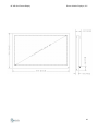
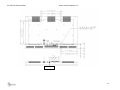
MECHANICAL .................................................................................................................................................. 39
APPENDIX E: DEFINITION OF TERMS.......................................................................................................... 40
WARRANTY EXCLUSIONS ............................................................................................................................ 41
OUTLINE DRAWINGS ..................................................................................................................................... 42
2
42” HD Gas Plasma Display
Rosen Aviation Displays, LLC
Introduction
Congratulations! You have purchased the world’s most advanced and highest resolution
42" HD gas plasma display with built-in motion adaptive line doubler/scalar and multiple
high definition television (HDTV) direct inputs. You have wisely invested by choosing to
use a digital plasma display. In addition, there are up to 8 video inputs and multiple
picture-in-picture (PIP) scenarios.
The picture quality of your gas plasma display system is the best in its class for analog or
digital video presentation. The images produced by this plasma display system are
stunning – providing movie-film clarity with very black blacks, very white whites, true-to-life
skin tones – and also giving a perception of looking through the screen, rather than at it.
There is no better match to DVD and HDTV systems.
This unit contains the most comprehensive image enhancement settings available for
plasma displays through an intuitive, user friendly on-screen display (OSD). The OSD can
be accessed by either the infrared universal remote control (IR) supplied with your system,
or by an RS-232 connection. The IR has single pushbutton direct access to source
selections, scalar control, PIP control, and power on/off.
In addition, the 42" HD gas plasma display’s digital video converter (DVC) incorporates an
advanced scalar that provides virtually unlimited zoom and pan capabilities. User
prescribed scalar presets are provided to allow quick and simple full-screen viewing with
common widescreen and anamorphic picture formats. The scalar incorporates motionadaptive processing to preserve picture focus and smooth movement over a wide range of
image conditions.
The HDTV-direct inputs incorporate proprietary adaptive component video conversion
interface:
Directly operates with 480i or 480p and up to 1080i
Operates with either bi-level or tri-level syncs
Operates with RGBHV VESA levels, including the Direct TV HD-DSS system
Wide signal level and offset adaptability
This manual emphasizes safety, to both the user and the equipment. This display,
although the lightest and thinnest in its class, is designed with ruggedness and capability
for high reliability. However, unless the user understands how the equipment is to be
handled and operated, full benefits of this system’s superior design and safety features
may not be realized. Please read this manual to fully understand the capabilities of the 42"
HD gas plasma display system.
3
42” HD Gas Plasma Display
Rosen Aviation Displays, LLC
Safety
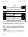
General Safety
Caution
Use the three-prong AC power cord supplied with the unit
to ensure that proper ground connection is maintained. A
safety ground lug is also provided on the unit and should
be used in accordance with your local electrical code.
Failure to provide a proper ground from the installation’s
power source may result in injury to personnel and serious
damage to the unit that would not be covered under
warranty.
Physical Safety
Caution
To reduce the risk of electric shock, do not remove any covers
from the display. Refer servicing to an authorized distributor or
factory trained service technician.
Warning
To avoid the risk of fire and electric shock, do not expose
this product to corrosive environments including ocean
spray, rain, or moisture; do not allow water or other liquids
in the unit. Exposure to such environments can cause
serious damage to the unit that would not be covered under
warranty.
Electromagnetic Compatibility (EMC)
This Equipment has been designed to meet the requirements of F.C.C. part 15 and CE
Directive 89/336/EEC with applicable harmonized standard EN-55022. These
requirements are designed to provide reasonable protection against harmful interference
when the equipment is operated in a commercial environment. This equipment generates,
uses, and can radiate radio frequency energy. Installation and Connection on page 6 of
this manual lists installation guidelines for the 42" HD gas plasma display to be FCC and
CE compliant. If this system is not installed and used in accordance with the instruction
manual, it may cause interference to radio communications.
Design Safety
This Equipment has been designed in accordance with the safety and material guidelines
set forth in CSA/UL 1950. Most of the materials are CSA/UL listed. The display has been
designed with a special glass front filter to minimize the risk of shattering, if broken. For
additional information on the safety verification status of this equipment, refer to Installation
and Connection (page 6).
4
42” HD Gas Plasma Display
Rosen Aviation Displays, LLC
Getting Started
Unpacking
Caution
Extreme caution should be taken when unpacking the digital monitor.
It has been designed for rugged use; however the display monitor
contains glass that could break if dropped. Appendix A (page 20)
shows how the 42" HD gas plasma display was packaged for
shipment. This will guide your efforts to unpack the system.
Carefully remove all components of the display from the packaging. Place the display face
(glass side) down on a soft, flat surface for ease of installation.
Note: The original packaging materials should be kept in case of service or
relocation. Replacement packaging may be purchased from the factory.
When the 42" HD digital display is installed and operating properly, please
store this manual in a safe place for future reference.
Pre-installation
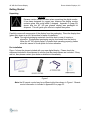
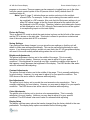
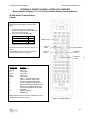
Figure 1 shows the pieces included with your new digital display. Please check the
equipment included in this shipment to confirm that the pieces shown are included. If they
are not, then please contact your dealer or distributor immediately.
Figure 1
Note: the IR remote control may be a different style than shown in Figure 1. Remote
control information is included in Appendix B on page 22.
5
42” HD Gas Plasma Display
Rosen Aviation Displays, LLC
Installation and Connection
Installation Warnings
The display unit shall be handled by at least two persons during installation and moving.
The display should be operated only when proper connection has been made to the
grounding stud provided on the unit.
Mounting the unit in any orientation with installer/user supplied mounting hardware is totally
the installer/user’s responsibility and liability.
Removal of the front bezel is strictly prohibited.
Exposure of the product to corrosive environments including ocean spray, rain or moisture,
or allowing water or other liquids to enter the unit shall void warranty.
Installation of the 42" HD gas plasma display into any aviation or mobile application must
be as specified in the applicable installation drawings. Any provided applicable addenda to
this manual for installation and/or maintenance must also be followed.
The display is cooled using air vents. Air vents must be open to free air in order to function
properly. The display must be installed with at least 1 inch of clearance above and below
the unit.
Failure to observe the safety configuration of the product and handle accordingly shall void
warranty.
6
42” HD Gas Plasma Display
Rosen Aviation Displays, LLC
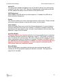
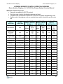
Operator Interface Connections
All operator connectors are located at the rear of the unit. Only one video source is
required for your new 42" HD gas plasma display. However, multiple video sources can be
connected at the same time.
IR Code Switch
Fuse Carrier
Video Bundle
Ground Stud
Figure 2
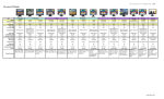
Up to 8 Video Inputs:
INPUT
DVI
RGB
CONNECTOR
TYPE
DVI 1.0
DVI 1.0/HDB15
DESCRIPTION
YPbPr
3 BNCs
Computer Digital RGB
Computer RGB or DTV/HDTV
Component
DTV/HDTV Component
S-Video
S-Video A (*)
Composite (* and **)
Composite (* and **)
Composite (* and **)
DIN4
DIN4
RCA
RCA
RCA
NTSC/PAL Baseband
NTSC/PAL Baseband
NTSC/PAL Baseband
NTSC/PAL Baseband
NTSC/PAL Baseband
BANDWIDTH
Up to 60Hz 768p
Up to 60Hz 768p
Up to 60Hz 768p or
30Hz 1080i
Interlaced STV
Interlaced STV
Interlaced STV
Interlaced STV
Interlaced STV
NOTE: A Source cannot be selected from the OSD unless it has been enabled.
See Input Port Enable on page 16.
*
**
With Video Bundle Accessory
Three composite inputs can be replaced by one component input with interlaced STV bandwidth.
Note: When connecting a video source to the display unit, keep in mind that a higher quality cable will
result in better picture quality.
7
42” HD Gas Plasma Display
Rosen Aviation Displays, LLC
DVI (Digital Visual Interface)
If your new display is being used with a computer with DVI output, connect a DVI cable to
this connector location and the other end to your computer. Your cable should not be
longer than necessary.
Analog RGB Input (Computer)
If your new display is being used with a computer that has only a VGA output, connect a
VGA cable with a DVI-Analog connector to this DVI/RGB connector location (see Figure 2
on page 7), and connect the other end to your computer’s VGA feature connector. Your
cable should not be longer than necessary.
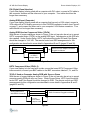
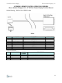
Analog RGB Used as Component Video (YPrPb)
With the use of proper cabling as shown in Figure 3, the unit can also be set up to accept
HDTV component video (YPrPb) on the analog RGB input. Adjustments on the OSD are
also needed. Under Source Setup, HDTV Input should be turned ON and Color Space
should be changed to YUV HD. The remote control and OSD arrangements for this
configuration are described in more detail in Appendices B and C (pages 22 and 30).
HDB15 to DVI-A Adapter Connector
Plugged into Monitor
YPrPb
Source
3 Coax
to HDB15
Adapter Cable
Figure 3
HDTV Component Video (YPbPr.2)
If your new display is to be used with a video source that uses HDTV Component Video
interconnection, connect your BNC cables to the BNC connectors labeled Y, Pr, and Pb.
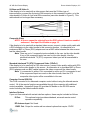
YPrPb.2 Used as Computer Analog RGB with Sync on Green
With the use of proper cabling as shown in Figure 4, the unit can also be set up to accept
computer analog RGB with sync on Green. Under Source Setup, HDTV Input should be
turned OFF and Color Space should be changed to RGB. The remote control and OSD
arrangements for this configuration are described in more detail in Appendices B and C
(pages 22 and 30).
Analog
Anolog RGB
RGBSource
Source
With
HDB15
Connector
with HDB15 Connector
BNCConnectors
Connectors Plugged
plugged into
BNC
intoMonitor
Monitor
3 Coax
3 Coax
fromHDB15
HDB15
from
Adapter Cable
Figure 4
8
42” HD Gas Plasma Display
Rosen Aviation Displays, LLC
S-Video and S-Video.A
If the display is to be used with a video source that uses the S-Video type of
interconnection, connect the 4-pin mini-DIN connector to this connector location, or to the
video bundle’s S-Video.A 4-pin mini-DIN connection (see video bundle in Figure 5). This
cable should not be longer than necessary.
Figure 5
Composite Video
NOTE: A Source cannot be selected from the OSD unless it has been enabled
and saved. See Input Port Enable on page 16.
If the display is to be used with a standard video source, connect a video quality cable with
a RCA connector via the video bundle to this connector location. An alternative is to
purchase a BNC to Phono (RCA) adapter and use a BNC cable between the video source
and the video bundle.
Note: There are up to 3 composite inputs available to the user via the video bundle.
If any of the composite inputs are used on the video bundle, then the
standard-interlaced TV (STV) component video input will be unavailable to
the user.
Standard-Interlaced TV (STV) Component Video (YPbPr.1)
If the display is to be used with a CAV video source, connect video quality cables with RCA
connectors via the video bundle to this source. An alternative is to purchase BNC to Phono
(RCA) adapters and use BNC cables between the video source and the video bundle.
Note: Y is connected to yellow, Pb is connected to white, and Pr is connected to red.
If the component inputs are used on the video bundle, then the STV
composite video inputs will be unavailable to the user.
Computer Control (RS-232)
This RJ45 connector is for advanced computer control without using the infrared remote
control. All of the remote functions are available through this connector with additional
controls available. Appendix B (page 22) provides full details on the RS-232 remote
control including the cable/connector details.
Interface Options
If your unit was ordered with certain interface options, these may be included as follows:
IR Out:
This optional output provides wideband, universal remote control
repeater compatibility.
RF Antenna Input: Not Used.
12VDC Out: Output for certain add-on external options that require 12VDC.
9
42” HD Gas Plasma Display
Rosen Aviation Displays, LLC
Input Power and Ground Connections
Caution
Ensure that the AC power cord is disconnected from the
AC power source before performing the following steps.
Ground Stud Connections
The back of the display has a ground stud that must be connected to an earth ground (see
Figure 2 on page 7). It is the installer’s responsibility to determine the local code for
materials and dimensional requirements for lug size, wire size, length and location of the
earth ground connections in the installation.
AC Power Connections
Place the power cord into the back of the unit. Do not connect the power to your wall plug
at this time.
Operator Controls and Indicators
IR Code Switch
On the back of the unit (see Figure 2 on page 7) is a switch labeled IR CODE that is
located between the video bundle input and IR output. It should be in the full down position
as set at the factory. The IR remote control supplied with your unit has been
preprogrammed to operate the OSD with the switch in this position. If you want to change
IR codes to avoid interference from other IR remote controls, you can select a different
switch setting and reprogram the IR to a different code set. See the information provided
with the IR remote control supplied with your unit for code-set and code-switch settings. For
additional information, refer to Appendix B on page 22.
Infrared Remote Control
The infrared remote control supplied with your new 42" HD gas plasma display is the main
user control for the system. It can access all the capabilities of your display. For full details
including the OSD, see Appendix B (page 22) and Appendix C (page 30). The summary
functions available via remote control are described in the following section on unit
operation.
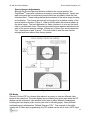
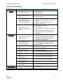
Remote Infrared Sensor
The remote control infrared sensor is located on the front of the display. As you are looking
at the front of the display, the sensor is located in the lower right hand corner of the frame
as shown in Figure 6. You will obtain the best performance from the remote control if you
aim it at this sensor.
10
42” HD Gas Plasma Display
Rosen Aviation Displays, LLC
IR Sensor
Figure 6
Unit Operation
After the installation is complete, plug the main power cord into the specified voltage outlet.
The unit has been set up at the factory so that it will turn on in the standby mode.
Remote Power On/Off
The remote control has a function that will only enable and disable the display’s screen (for
example: standby mode). The unit will remain in the standby mode when the display
screen is disabled by remote control. In this mode, the fans will not operate, and the unit
will draw only a few watts of power. The unit can be enabled again by using the IR, or by
RS232 command.
On Screen Display (OSD)
Invoking the OSD will access the system controls, which are fully detailed in Appendix C
(page 30). The primary system control functions or modes are summarized in the following
paragraphs.
Source Selection
Source selection by the remote control, in most installations, will only have to be performed
one time. Once you select the source: Computer RGB (VGA), Composite.Y, Composite.R,
Composite.W, S-Video, S-Video.A, YPbPr.1, YPbPr.2, or DVI, the system will remember
your source and you will not have to re-select it.
If you are using more than one source for video, you will have to change between the
different sources. The unit will always remember your last video source selection when
enabled from standby. However, if the unit is powered down improperly (for example: AC
power is removed), then the video source selection last saved by RS232 or the OSD’s
SAVE selection will be remembered and shown on the screen at power-up.
IR Universal Remote Control Discrete Commands (Direct IR)
Regardless of which menu the user is viewing, pressing one of the discrete command
buttons on the IR causes a corresponding immediate action. These discrete command
buttons are detailed in Appendices B and C, and are set up at the factory as defaults.
However, they are programmable through OSD menus. The Direct IR Menu is accessible
11
42” HD Gas Plasma Display
Rosen Aviation Displays, LLC
as factory default discrete command button 9. The user can immediately recall the
discrete command button assignments by pushing 9 on the IR.
Note: This assumes that the user has not changed this particular factory default.
Analog RGB/DVI Modes
Once the VGA/SVGA mode is invoked by selecting the VGA source, menu selections are
available for adjusting color, contrast, brightness and interface synchronization as well as
FlexiScreenTM control. After selecting a menu function, the OSD presents a bar and a
value for your reference while performing the adjustment or function control.
Baseband Video Modes (Composite, Component, S-Video)
When a baseband video mode is invoked by selecting one of the baseband video sources,
menu selections are available for adjusting color, contrast, brightness and interface
variables as well as FlexiScreenTM control. After selecting a menu function, the OSD
presents a bar and a value for your reference while performing the adjustment or function
control.
FlexiScreenTM Scaler
FlexiScreenTM controls image sizing and positioning on the display screen for each of the
sources provided.
Using the FlexiScreenTM Scaler
The goal of FlexiScreenTM is to enhance the viewing experience by allowing the user to
tailor the image to their liking. Factory preset formats of the more popular settings are
provided per source input. These format settings target a wide range of media formats
and allow the user to create their ideal image. Follow the quick and easy steps listed
below to customize the image using the FlexiScreenTM. The steps are organized as a
top-down approach; begin at the top of the list and work down. Any time the image
becomes satisfactory, abort the steps and exit the OSD menu with a save. Saving the
settings to memory will preserve the configuration for the future.
With the desired source input selected, bring up the FlexiScreen menu.
Choose a predefined source format that best fits the source image to the screen.
Verify the following:
The Display Aspect Ratio (“Disp Aspect”) setting fills the screen
appropriately.
The choices are arranged by popular film mastering formats.
The four remaining settings are the discrete parameters that make up the
actual source aperture used by the built-in scalar.
Height and width along with the horizontal and vertical offsets are provided to
allow the user ultimate control. See Figures 7 and 8 for more details.
Altering any of these four values causes the “Src:” description to read
“Custom”. This is provided to alert the user that the settings have been
altered from factory presets.
12
42” HD Gas Plasma Display
Rosen Aviation Displays, LLC
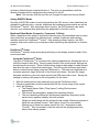
Display Aspect Ratio Selections
“16:9“ will cause the image to fill the entire width of the display screen.
“4:3” will cause the image to only fill a portion of the display screen to achieve a 4:3
aspect ratio.
“1:1” (not shown below) will cause the image to fill the screen with a direct one for
one pixel association with the source aperture adjustments. For example, if you
chose a 600 width and a 400 height, then a 600 x 400 window should be visible on
the display screen.
“Panoramic” will cause the center of the screen to be displayed in a normal fashion
and the outside 10% of the image (left and right side only) will be stretched to fit the
full size of the screen.
“Letterbox” Image
Shown 4:3
“Letterbox” Image Shown 16:9
With Reduced Source Aperture
to Minimized “Black Bars”
“Letterbox” Image
Shown 16:9
“Letterbox” Image Shown With
Panoramic View Shown
Figure 7
Source Aperture Selections
Cycle through Source Aperture Selection choices to initialize the source aperture
adjustments listed below. These settings identify a particular group of source aperture
adjustments that have been optimized for the “widescreen” or “letterbox” type movies.
Each setting targets the minimization of black bars encoded on movie media, while
maintaining an inherent aspect ratio to diminish distortions. Choices are listed as film
mastering formats.
13
42” HD Gas Plasma Display
Rosen Aviation Displays, LLC
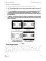
Source Aperture Adjustments
Although the Source Aperture Selection initializes the source aperture, the
FlexiScreenTM menu also includes provisions for manual adjustments. Height and
width along with the horizontal and vertical offsets are provided to allow the user
ultimate control. These settings define the boundaries of the active image showing
on the display. The source aperture can be thought of as a window overlay of the
source frame as shown in Figure 8. What is defined within this window makes up
the active image. The best application for these functions is to crop out the black
bars of a widescreen movie. There are associated source aperture adjustments for
each of the source aperture settings. Altering any of these four values causes the
“Src:” description to read “Custom”. This is provided to alert the user that the
settings have been altered from factory presets.
Figure 8
PIP Modes
Picture in Picture (PIP) is a feature that makes it very easy to view two different video
inputs at the same time. The main display can be showing any active input while the PIP
window can be activated to view another active input in many different combinations,
including the main display video source (see note on following page). Many different
combinations are referenced as “Multiple Scenario PIPs”. One example is that while
viewing the S-Video input programming, the PIP window can be set to view a HDTV input
14
42” HD Gas Plasma Display
Rosen Aviation Displays, LLC
program or vice versa. These programs can be swapped or toggled from one to the other
using the remote control system or the IR (remote control: factory default direct IR
command button 8).
Note: Figure 2 (page 7) indicates there are certain exclusions to the multiple
scenario PIPs. For example, 2 video inputs sharing the same switch cannot
be combined in a PIP scenario. Also note that the Flexiscreen settings do not
affect PIP widow images in that the format delivered at the switch input will
be displayed in the PIP window. Therefore, letterbox and widescreen formats
will be displayed as such in PIP, although Flexiscreen factors will be applied
to corresponding inputs on the main display.
Picture by Picture
This is a special PIP mode in which the main picture is shown on the left side of the screen
and the PIP is shown on the right side. This mode is offered to provide an unobstructed
view of the main picture while a PIP is activated.
Saving Settings
If any settings have been changed, you can store the new settings so that the unit will
default to these new settings automatically. This can be performed individually for each
source. If you change any settings, and do not save them, the 42" HD gas plasma display
will revert to the most recently saved settings when the unit is turned off.
Brightness Adjustments
The picture brightness is factory set to the middle of the range. This is normally
satisfactory for most viewing. However you may want to adjust it for your specific
conditions. If the brightness is turned up very high, a washout condition might appear. If
this happens, simply decrease the brightness of the display. The OSD shows a bar and a
value for reference while adjusting.
Contrast Adjustments
The picture contrast is factory set to the middle of the range. This is normally satisfactory
for most viewing. However, you may want to adjust it for your specific conditions. The
OSD shows a bar and a value for reference while adjusting.
Hue Adjustments
The picture hue is factory set to provide the most accurate color reproduction. This is
normally satisfactory for most viewing. However you may want to adjust it for your specific
conditions. The OSD shows a bar and a value for reference while adjusting.
Color Adjustments
The picture color is factory set to give true color representations. This is normally
satisfactory for most viewing. However you may want to adjust it for your specific
conditions. The OSD shows a bar and a value for reference while adjusting.
Display Setup
The display unit has many options that can be changed from the factory default to the user
preferences. The display setup options are detailed on the following page.
15
42” HD Gas Plasma Display
Rosen Aviation Displays, LLC
Instant On
This setup option enables the display to turn on and show video as soon as the power
is applied to the unit. If set to OFF, this option keeps the unit in the standby mode until
the user enables the display via the IR remote or the RS232 control.
OSD Background
When enabled, the OSD will have a solid background. If disabled, the OSD will not
have a distinctive background.
Freeze
This function enables you to freeze the image currently on the screen. Please note that
this function does not pause or stop the video source, only the screen.
Color Gamma
Within the Display Setup menu is the Color Gamma adjustments. In normal situations
this menu should not have to be used. However, if conditions or situations require an
adjustment to the color gamma curves, this can be accomplished in this sub menu. See
Appendix C (page 30) for full details.
Input Port Enable
This setup menu is very important while the unit is being installed (use in conjunction
with Operator Interface Connections, beginning on page 7). The installer is required to
turn on or off the unit’s various inputs. This menu, once set, should normally not require
further modifications after unit installation is complete. This Menu is a SMART menu in
that it will not allow conflicting inputs to be enabled. You must save the settings once
they have been set for the installation. A source cannot be selected from the
OSD unless it has been enabled and saved.
Direct IR Setup
Direct IR Setup menu is provided so that the user can customize the way the IR
controls the 42" HD gas plasma display with discrete commands. See Appendix B
(page 22) for full details.
16
42” HD Gas Plasma Display
Rosen Aviation Displays, LLC
Care and Maintenance
Caution
Do not allow water or other liquids to enter the unit. This can cause
serious damage to the unit that would be very costly to repair.
Always be sure that the AC power is turned off during cleaning.
Screen Cleaning
The screen can be cleaned using a very mild glass cleaner that is non-abrasive, and a lens
grade tissue for optical surfaces. Do not spray the glass cleaner directly onto the glass.
Spray the glass cleaner onto the tissue, and then clean the glass.
Air Vent Cleaning
All air vents of the display should be inspected periodically for buildup of dust or other
obstructions. Such obstructions can interfere with the proper cooling of the unit causing
reduced performance and reliability. Air vent obstructions can be removed by vacuuming
around the air vents.
Fuses
The unit uses ONLY a 5 x 20mm, 5 Amp, 250V time-delay type fuse with a 1500 Amp
interrupting rating such as Littlefuse® 215005 or equivalent. Replace fuse with same type
and rating only. The fuse is located in a snap-in carrier below the input power receptacle.
See Figure 2 (page 7).
Recommendation for Screen Saver
The plasma display panel in the unit incorporates phosphors. These phosphors could be
damaged by prolonged display of still pictures and/or text. Therefore a screen saver
program should be employed in still picture applications. Such applications especially
include computer graphics. However, we often forget that some video sources such as
DVD players can also put up menus and still pictures and/or text. Therefore, protect
against these situations also.
17
42” HD Gas Plasma Display
Rosen Aviation Displays, LLC
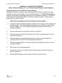
Operator Troubleshooting
Category
Power
Symptom
Unit does not come on
Unit comes on but display
does not light or have
O.S.D.
1. Batteries in remote
2. Remote power on
Remote does not work or
unit will not turn on with
infrared remote control
Display turns on with
O.S.D. but does not show
video
All Modes
System doesn’t remember
changed settings
Picture seems distorted:
circles are not round—
video or RGB modes
Picture is too dark or too
light
Picture has too much or
not enough contrast
Picture is too high on
screen
Picture is too low on
screen
Picture is too far to the left
of the screen
Picture is too far to the
right of the screen
Picture does not have the
correct height
Picture does not have the
correct width
Video Modes
Check
1. Input power cord connections
2. Rear line fuse
3. Power source
Pictures are too green or
purple
1. Replace infrared remote control batteries
with new, good batteries and reprogram the
remote
2. Ensure that the infrared sensor on the
display is not blocked
1. Enable and save the video input per Input
Port Enable on page 16.
2. Video source
3. Video cables from the video source to the
unit
4. Source selection for the display with the
remote control (Refer to Remote Control
commands)
1. No settings are saved until SAVE is
manually selected from within the menu. If
settings are changed and not saved, the
next power up will return the unit to it’s
previously saved parameters.
1. This is usually caused by selecting modes in
the FlexiScreen menu that don’t maintain
pixel correlation; Select Standard or 4:3
mode to confirm
1. O.S.D. for Brightness control
2. Source for poor quality
1. O.S.D. for Contrast control
2. Source for poor quality
1. O.S.D. and remote control for position
1. O.S.D. and remote control for position
1. O.S.D. and remote control for position
1. O.S.D. and remote control for position
1. O.S.D. and remote control for correct height
1. O.S.D. and remote control for correct width
1. HUE in O.S.D.
18
42” HD Gas Plasma Display
Category
DVI, Analog
RGB Mode
Rosen Aviation Displays, LLC
Symptom
Screen does not sync up
Blue is dim or too bright
Green is dim or too bright
Red is dim or too bright
Composite
Video, S video
and YPbPr.1
Component
Video YPbPr.2
1. Input settings for the computer. They should
be one of the acceptable display rates listed
in Appendix D (page 38)
1. O.S.D. Blue Gain Adjustment
1. O.S.D. Green Gain Adjustment
1. O.S.D. Red Gain Adjustment
No sync and appearance
has mixed up colors or
black and white
1. O.S.D. for PAL or NTSC format, match with
source format
Picture appears to be
Black and white
1.
2.
3.
4.
The picture appears black
and white
The colors are wrong
Special Modes
Check
Source connection
Source to interface cable and connections
Color in O.S.D.
Source might be Black and White
1. Cables from the source for proper
connections, for example, y to y
2. Color in O.S.D.
3. Source might be Black and White
1. Cables from the source for proper
connections, for example, y to y
2. HUE in O.S.D.
The picture appears not to
sync up or the O.S.D.
displays “No Video
Source”
Will not accept interlacestyle input.
1. This input will not accept interlace-style
input. Use YPbPr1.
RS232C interface is not
functioning
1. Refer to Appendix C (page 30) for all
information
1. Cables from the source for proper
connections, for example, y to y
Service and Support
Rosen Aviation Displays, LLC
www.rosenaviation.com
PH: (541) 434-4512
Packaging and Shipping
Please repack your unit in the same fashion as it was originally packed into the shipping
container. Please include all parts of your unit so that the unit can be fully repaired, tested
and returned to you in good working order. The sender is responsible for damage to
displays that are not properly packaged for shipment. See Appendix A (page 20) for
illustration/instruction on how to package the unit for shipment in its original shipping
container. Consult your dealer or the authorized factory service center with any questions.
19
42” HD Gas Plasma Display
Rosen Aviation Displays, LLC
APPENDIX A: PACKING FOR SHIPMENT
Rosen Aviation Displays, LLC, 42" HD Gas Plasma Display Technical Manual
Shipping Procedure for 42" HD Gas Plasma Display
In the event that the 42” display needs to be shipped, the following procedures must be
followed to protect it from damage. Rosen Aviation Displays, LLC is NOT Responsible for
damage to equipment not packaged according to the guidelines listed below. Customer is
responsible for freight charges back to the factory for warranty repair. Factory will pay
return freight via ground service.
Note: Save all packaging in case the display must be shipped.
1.
Locate the original corrugated shipping container, foam cushions, wooden pallet and
reusable straps. If the original shipping materials are not available, contact Rosen
Aviation Displays, LLC for information regarding the purchase of replacement
shipping packaging.
2.
Ensure that the box is on the pallet as shown in Figure A.1.
3.
Place bottom foam cushion in sides and bottom of box, noting orientation of notch
as shown in Figure A.1.
4.
Wrap the display in the pink polyethylene plastic sheet to protect the painted
surfaces and glass front filter from damage during shipment.
5.
Place the wrapped display into the box and insert the other foam cushion over the
top edge of display.
6.
Seal the box lid with packaging tape.
7.
Secure the outer box to the pallet with two polypropylene straps and buckles as
shown in Figure A.1.
8.
Place FRAGILE labels on all four sides and the top of the outer box.
20
42” HD Gas Plasma Display
Rosen Aviation Displays, LLC
APPENDIX A: PACKING FOR SHIPMENT
Rosen Aviation Displays, LLC, 42" HD Gas Plasma Display Technical Manual
Notch
Notch
Figure A.1
21
42” HD Gas Plasma Display
Rosen Aviation Displays, LLC
APPENDIX B: REMOTE CONTROL OPERATION OVERVIEW
Rosen Aviation Displays, LLC, 42" HD Gas Plasma Display Technical Manual
The standard remote control system for the 42" HD gas plasma display is described in this
appendix.
The standard system has many user settings, which can be saved to non-volatile system
memory for the user’s convenience. This allows the user to set up the system once and
restore their settings after the power has been shut off. User settings are restored from
non-volatile memory during the following conditions:
Toggling the display out of stand-by mode
Switching input sources
Selecting exit with cancel from the OSD menu system
Entering the cancel command from the RS232 terminal interface
Control settings via the hand-held IR remote control unit or a RS232 terminal connection.
Infrared (IR) Universal Remote Control
IR button description
The IR remote control operates from 12 buttons described below. These buttons allow
display control by navigating through the OSD menu system and selecting the many
functions:
Power = toggles the display in and out of stand-by mode
Up & Down moves the active row respectively
Left & Right manipulates or performs the action of the menu item selected by the active
row
0 to 9 are used to directly switch to selected inputs or menus
MENU toggles the OSD visibility
Essentially any IR remote control with the button options listed above that can be
programmed (including programming through a learn mode) can be used.
Some examples of IR’s that have been used with 42" HD gas plasma display products are:
Allegro (Zenith) MBC 4030/4035/4430/4435
RCA SystemLink 5AV
Home Theater Master (Universal Remote Control, Inc.) SL-9000, SL-8000
Universal Electronics URC-8080 “A/V Producer”, URC-3030 “One For All”
Bose Life Style 35 IR Remote Control System
The above examples are neither recommendations nor representations of full evaluations
for them. The standard IR provided with the 42" HD gas plasma display is factory
preprogrammed and integrated for specific performance criteria (see Appendix D –
Specifications on page 38).
22
42” HD Gas Plasma Display
Rosen Aviation Displays, LLC
APPENDIX B: REMOTE CONTROL OPERATION OVERVIEW
Rosen Aviation Displays, LLC, 42" HD Gas Plasma Display Technical Manual
SL8000 Home Theater Remote
Control
To Program the Remote control for operation
with the 42HD Video Display, follow the steps
below.
1.
2.
Press and hold the TV and the Mute
buttons at the same time until the display on
the remote control say SET.
Enter in one of the following codes.
IR Code Switch Setting
1
2
3
3.
Code
004
138
019
Display Power
Press the TV button to save the set up.
See the IR Code Switch location in Figure 2, on
page 7.
Find additional IR information under Operator
Controls and Indicators, on page 10.
OSD Up
Control
Menu ON/OFF
OSD Left
Control
OSD Right
Control
OSD Down
Control
SL-8000 IR
Remote Key
POWER
PAUSE
F.F
STOP
REW
MENU
1
2
3
4
5
6
7
8
9
0
42 HD
Function
Power ON/OFF
Cursor Up
Cursor Right
Cursor Down
Cursor Left
OSD ON/OFF
YPbPr.1 SOURCE SELECTION
YPbPr.2 SOURCE SELECTION
S VIDEO SOURCE SELECTION
S VIDEO.A SOURCE SELECTION
ANALOG RGB SOURCE SELECTION
DIGITAL DVI SOURCE SELECTION
PIP TOGGLE SOURCE SELECTION
PIP SWAP
DIRECT IR MENU
POWER OFF
Note: These functions are the Factory Default and can be
changed in the OSD menu system.
Figure C.1 SL8000 Remote
23
42” HD Gas Plasma Display
Rosen Aviation Displays, LLC
APPENDIX B: REMOTE CONTROL OPERATION OVERVIEW
Rosen Aviation Displays, LLC, 42" HD Gas Plasma Display Technical Manual
IR Remote Control Keycodes
Keycodes correspond to NEC IR protocol
Only the codes to which the display responds are listed
Program Code corresponds to the One For All, RCA or Allegro programming code
Names next to the program code are manufacturers which commonly use this code
set
IR REMOTE
SELECT SWITCH
DOWN (1)
IR REMOTE
SELECT SWITCH
MIDDLE (2)
IR REMOTE
SELECT
SWITCH UP (3)
One 4
HT
All
Master
RCA
Allegro
0021
019
008
NONE
KEY /
FUNCTION
42 HD
FUNCTION
Manufacturer
N/A
HT
Master
One 4 All
RCA
Allegro
HT
Master
One 4 All
RCA
Allegro
Program Code
(OFA, RCA,
Allegro)
N/A
004
0186
033
139
138
0027
009
114
Control Code
N/A
$20DF
$A857
$02FD
$04FB
$14EB
$08F7
Power
Power ON/OFF
$10
$48
$48
$88
$D0
$88
Channel Up
Cursor Up
$60
$38
$41
$68
$78
$68
Volume +
Cursor Right
$30
$68
$98
$48
$F8
$48
Channel Down
Cursor Down
$E0
$B8
$C1
$58
$B8
$58
Volume -
Cursor Left
$B0
$E8
$B8
$50
$38
$50
0
DIR. IR 0
$08
$D0
$00
$10
$90
$10
1
DIR. IR 1
$98
$80
$80
$00
$00
$00
2
DIR. IR 2
$48
$40
$40
$40
$80
$40
3
DIR. IR 3
$C8
$C0
$C0
$C0
$40
$C0
4
DIR. IR 4
$28
$20
$20
$A8
$C0
$A8
5
DIR. IR 5
$A8
$A0
$A0
$98
$20
$98
6
DIR. IR 6
$68
$60
$60
$D0
$A0
$D0
7
DIR. IR 7
$E8
$E0
$E0
$28
$60
$28
8
DIR. IR 8
$18
$10
$10
$18
$E0
$18
9
DIR. IR 9
$98
$90
$90
$C8
$10
$C8
Recall or Menu
OSD ON/OFF
$C2
$88
$01
$E0
$D8
$E0
24
42” HD Gas Plasma Display
Rosen Aviation Displays, LLC
APPENDIX B: REMOTE CONTROL OPERATION OVERVIEW
Rosen Aviation Displays, LLC, 42" HD Gas Plasma Display Technical Manual
Menus and RS232 Commands for the HD Digital Video Controller
General Description
The extensive menu and RS232 control system that has been built into the HD digital video
controller (HD DVC) has been designed for simple navigation, user friendliness, and
application diversity. At the same time, it provides the most exhaustive submenu system
available for application fine-tuning of the displayed video signal. Menus are described in
full detail in Appendix C (page 30).
To bring up the menu system, press MENU on the remote control while in the TV mode. To
move through the menus, use the up arrow (pause), right arrow (FF), left arrow (REW),
and the down arrow (STOP) on the remote. To turn the menu off, either wait for the time
out or press MENU again.
Menus will appear similar to those stated below, however once sources are connected and
the application varies the settings, these menus might appear slightly different. These
differences will be noted throughout the text of this document.
Definitions
•
Menu selections with an arrow to their right only will take you to a lower level menu;
excluding the Restore Factory Settings selection
•
The icon that resembles a sun indicates brightness options
•
The icon that resembles a moon indicates contrast options
•
Hue is the tint of the colors on the displayed input
•
Color is defined as the amount of the displayed video’s color saturation
NOTE: No settings are saved until SAVE is manually selected from within the
menu. If settings are changed and not saved, the next power up will return
the unit to it’s previously saved parameters.
25
42” HD Gas Plasma Display
Rosen Aviation Displays, LLC
APPENDIX B: REMOTE CONTROL OPERATION OVERVIEW
Rosen Aviation Displays, LLC, 42" HD Gas Plasma Display Technical Manual
RS232 Control
The following chart describes the RS232 commands. The commands must be followed by
a carriage return <CR>. Some commands require values to be entered such as
Brightness. These values are to be entered in as hexadecimal ASCII with leading zeros
when necessary. For example, brt0A<CR> requests a brightness value of decimal 10.
Refer to the Comments column for more details regarding a particular command.
Note: The range of values for FlexiScreen commands vary depending upon the
input source. Improper settings may cause loss of sync to the input. Syntax
is case sensitive. To retain adjusted settings, select SAVE before shutting off
power. See the RS232 setup section for cable configuration and terminal set
up information.
Table C1: Video Board HC12 Software RS232 Command Set
SYSTEM COMMANDS
Power Toggle
Power ON
Power OFF
Version Display
Repeat Last Command
Save Settings To Memory
Cancel Changes
IR Control Lock Out
SYNTAX
pwr<CR>
pwr1<CR>
pwr0<CR>
ver<CR>
<CR>
save<CR>
cancel<CR>
irX<CR>
Instant On Enable
ioeX<CR>
Freeze Input Enable
Restore Factory Defaults
Clear Terminal Screen
Display Data In Hexadecimal
frzX<CR>
fact<CR>
clr<CR>
hex<CR>
Display Data In Decimal
FlexiScreen COMMANDS
Display Aperture Selection
Source Aperture Selection
Source Aperture Width
Source Aperture Height
Source Aperture Horizontal
Position
Source Aperture Vertical
Position
COMMENTS
necessary to make any changes permanent
restores last saved settings
where X = {0 = OFF, 1 = ON}, Default of OFF will return upon
cold power up
where X = {0 = OFF, 1 = ON}, how unit will respond upon cold
power up
where X = {0 = OFF, 1 = ON}
data displayed such as in device register dumps will be
displayed accordingly
dec<CR>
data displayed such as in device register dumps will be
displayed accordingly
SYNTAX
COMMENTS
dapX<CR>
where X is a 1 byte ASCII hex value (8 bit), range {x0…x3}
sapX<CR>
where X is a 1 byte ASCII hex value (8 bit), range {x0…x7}
swiXXXX<CR> where XXXX is 4 byte ASCII hex value (16 bit),
custom range {x0001…(dependent upon input source)}
shtXXXX<CR> where XXXX is 4 byte ASCII hex value (16 bit),
custom range {x0001…(dependent upon input source)}
shpXXXX<CR> where XXXX is 4 byte ASCII hex value (16 bit),
custom range {x0001…(dependent upon input source)}
svpXXXX<CR> where XXXX is 4 byte ASCII hex value (16 bit),
custom range {x0001…(dependent upon input source)}
26
42” HD Gas Plasma Display
Rosen Aviation Displays, LLC
APPENDIX B: REMOTE CONTROL OPERATION OVERVIEW
Rosen Aviation Displays, LLC, 42" HD Gas Plasma Display Technical Manual
Main Display Commands
Source Selection
SYNTAX
srcX<CR>
Brightness
Contrast
Hue
Color Saturation
Red Magnitude For RGB
Inputs
Blue Magnitude For RGB
Inputs
Green Magnitude For RGB
Inputs
Sharpness, Fine
Sharpness, Coarse
Panel Brightness
Input Color Space Selection
Input Select Notification
brtXX<CR>
conXX<CR>
hueXX<CR>
satXX<CR>
redXX<CR>
COMMENTS
where X =
0 Analog RGB Input (HDTV)
1 YPbPr.2 Input (HDTV)
2 DVI Input
3 Composite, TV Tuner Option
4 Composite, Video bundle, yellow
5 Composite, Video bundle, red
6 Composite, Video bundle, white
7 YPbPr.1 (analog), Video bundle
8 S-Video, fixed mini DIN
9 S-Video, Video bundle
where XX is 2 byte ASCII hex value (8 bit), range {x00…x64}
where XX is 2 byte ASCII hex value (8 bit), range {x00…x64}
where XX is 2 byte ASCII hex value (8 bit), range {x00…x64}
where XX is 2 byte ASCII hex value (8 bit), range {x00…x64}
where XX is 2 byte ASCII hex value (8 bit), range {x00…x64}
bluXX<CR>
where XX is 2 byte ASCII hex value (8 bit), range {x00…x64}
grnXX<CR>
where XX is 2 byte ASCII hex value (8 bit), range {x00…x64}
Color Gamma Value
Color Gamma Scale Factor
shrpXX<CR>
shrpcXX<CR>
pbrtXX<CR>
cscX<CR>
isnX<CR>
where XX is 2 byte ASCII hex value (8 bit), range {x00…x0F}
where XX is 2 byte ASCII hex value (8 bit), range {x00…x0A}
where XX is 2 byte ASCII hex value (8 bit), range {x00…xFF}
where X = {0 = RGB, 1 = YUV SD, 2 = YUV HD}
where X = {0 = OFF, 1 = ON}, When enabled, "SEL n" is sent to
the serial port. Refer to the Hex Value table below for a
complete listing of "n".
gamCXX<CR> where C = {r,g, or b} and XX = ASCII hexadecimal value, range
{x00…x14}
gsfCXX<CR> where C = {r,g, or b} and XX = ASCII hexadecimal value, range
{x00…x64}
SYNTAX
COMMENTS
Analog RGB And Yprpb.2
Only
Red Gain Adjustment
anrXX<CR>
Blue Gain Adjustment
anbXX<CR>
Green Gain Adjustment
angXX<CR>
Red Offset Adjustment
redoXX<CR>
Blue Offset Adjustment
bluoXX<CR>
Green Offset Adjustment
grnoXX<CR>
Clock Phase
phsXX<CR>
Clock Frequency Pll
clkXXXX<CR>
Clamp Position
Clamp Width
Sync On Green Threshold
Sync Separator Threshold
Pre-Coast Setting
Post-Coast Setting
HDTV Input Enable
Automatic Gain Control
clpXX<CR>
clpwXX<CR>
sogXX<CR>
sstXX<CR>
prcXX<CR>
pocXX<CR>
hdtvX<CR>
agcX<CR>
where XX is 2 byte ASCII hex value (8 bit), range {x00…xFF}
where XX is 2 byte ASCII hex value (8 bit), range {x00…xFF}
where XX is 2 byte ASCII hex value (8 bit), range {x00…xFF}
where XX is 2 byte ASCII hex value (8 bit), range {x00…x7F}
where XX is 2 byte ASCII hex value (8 bit), range {x00…x7F}
where XX is 2 byte ASCII hex value (8 bit), range {x00…x7F}
where XX is 2 byte ASCII hex value (8 bit), range {x00…xFF}
where XXXX is 4 byte ASCII hex value (16 bit), range
{x0001…x0FFF}
where XX is 2 byte ASCII hex value (8 bit), range {x00…xFF}
where XX is 2 byte ASCII hex value (8 bit), range {x00…xFF}
where XX is 2 byte ASCII hex value (8 bit), range {x00…x1F}
where XX is 2 byte ASCII hex value (8 bit), range {x00…xFF}
where XX is 2 byte ASCII hex value (8 bit), range {x00…xFF}
where XX is 2 byte ASCII hex value (8 bit), range {x00…xFF}
where X = {0 = OFF, 1 = ON}
where X = {0 = OFF, 1 = ON}
27
42” HD Gas Plasma Display
Rosen Aviation Displays, LLC
APPENDIX B: REMOTE CONTROL OPERATION OVERVIEW
Rosen Aviation Displays, LLC, 42" HD Gas Plasma Display Technical Manual
PIP COMMANDS
SYNTAX
PIP Window Enable Toggle
PIP Window Enable
PIP Source Selection
pip<CR>
pipX<CR>
psrcX<CR>
PIP Side By Side Enable
PIP Swap With Main Image
Pip Input Color Space
Selection
pssX<CR>
pswp<CR>
pcscX<CR>
OSM COMMANDS
OSM Ctrl: UP
OSM Ctrl: DOWN
OSM Ctrl: RIGHT
OSM Ctrl: LEFT
OSM Display/Hide Toggle
Refresh OSD
Osm Background Enable
SYNTAX
<ESC>OA
<ESC>OB
<ESC>OC
<ESC>OD
menu<CR>
rm<CR>
obeX<CR>
COMMENTS
where X = {0 = OFF, 1 = ON}
where X = {0 - 9}, Refer to the Hex Value table below for a
complete listing of "X".
where X = {0 = OFF, 1 = ON}
where X = {0 = RGB, 1 = YUV SD, 2 = YUV HD}
COMMENTS
same as pressing UP arrow key on keyboard or IR
same as pressing DOWN arrow key on keyboard or IR
same as pressing RIGHT arrow key on keyboard or IR
same as pressing LEFT arrow key on keyboard or IR
same as pressing MENU on IR
where X = {0 = OFF, 1 = ON}
RS232 Setup Information
You will find the outline drawing for the RS232 cable on page 29.
The communications port requires the following set up and parameters:
38.4KB, 8 bit, 1 stop bit, no parity, no handshake.
If you are emulating a terminal:
• VT100 is recommended
• ASCII Sending: Carriage Return only on enter. Do NOT include line feed
• ASCII Receiving: Append line feeds to incoming line ends
28
42” HD Gas Plasma Display
Rosen Aviation Displays, LLC
APPENDIX B: REMOTE CONTROL OPERATION OVERVIEW
Rosen Aviation Displays, LLC, 42" HD Gas Plasma Display Technical Manual
Outline Drawing, RJ45 to Sub D RS232 cable
Front View
Front View
25 feet
RJ45
1
2
3
4
5
6
7
8
COLOR
Blue
Blue/white
Orange
Orange/white
Green
Green/white
Brown
Brown/white
Recommended Parts
QTY
MANUFACTURER
1
1
1
25 ft
Amp
Amp
Amp
Belden
DESCRIPTION
DSR (in)
DTR (out)
RD (data in)
GND
TD (data out)
GND
CTS (in)
RTS (out)
No connection
PART
NUMBER
5-554720-3
207826-3
17-1724-1
1229A1
SUB D 9 PIN
6
4
3
5
2
5
8
7
1
DESCRIPTION
Connector,Male,RJ45, crimp, round cable, 8 position
Connector, Female, Sub D 9 pin, solder cup
Hood
Cable, 4 twisted pair, Cat 5, solid 24 awg
29
42” HD Gas Plasma Display
Rosen Aviation Displays, LLC
APPENDIX C: OSD MENU STRUCTURE & COMMANDS
Rosen Aviation Displays, LLC, 42" HD Gas Plasma Display Technical Manual
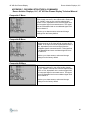
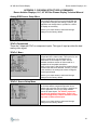
Composite.Y Menu
This menu is for Composite.Y input. It is the yellow
RCA female connector in the video bundle, thereby the
“Y”. “NONE” in the top line could be replaced with
NTSC or PAL, dependant on the received signal from
the composite signal’s connected source. This signal
has to be Baseband and not a modulated signal such
as on channel 3.
Use the up or down arrows to select and change
settings from the factory default.
Composite.R Menu
This menu is for Composite.R input. It is the red, RCA
female connector in the video bundle, thereby the “R”.
“NONE” in the top line could be replaced with NTSC or
PAL, dependant on the received signal from the
composite signal’s connected source. This signal has
to be Baseband and not a modulated signal such as
on channel 3.
Use the up or down arrows to select and change
settings from the factory default.
Composite.W Menu
This menu is for Composite.W input. It is the white,
RCA female connector in the video bundle, thereby
the “W”. “NONE” in the top line could be replaced with
NTSC or PAL, dependant on the received signal from
the composite signal’s connected source. This signal
has to be Baseband and not a modulated signal such
as on channel 3.
Use the up or down arrows to select and change
settings from the factory default.
30
42” HD Gas Plasma Display
Rosen Aviation Displays, LLC
APPENDIX C: OSD MENU STRUCTURE & COMMANDS
Rosen Aviation Displays, LLC, 42" HD Gas Plasma Display Technical Manual
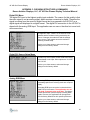
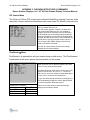
Composite Source Setup menu
This menu is common to all composite sources. Any
changes here will vary the input source settings for all
composite inputs. The active menu items are
brightness, contrast, hue, color, and sharpness. The
CAV items are for a different input. Do not adjust
the CAV items while in the composite mode.
See the YPbPr.1 menu on page 33.
Use the up or down arrows to select and change
settings from the factory default.
S Video Menu
There are 2 S-Video inputs to the HD DVC. One is
direct to the HD DVC and the other is via the video
bundle.
The S-Video input is to control the S-Video input
directly to the HD DVC. “NONE” in the top line could
be replaced with NTSC or PAL, dependant on the
received signal from the composite signal’s connected
source.
Use the up or down arrows to select and change
settings from the factory default.
S Video.A Menu
The S-Video input is to control the S-Video input via
the video bundle to the HD DVC. “NONE” in the top
line could be replaced with NTSC or PAL, dependant
on the received signal from the composite signal’s
connected source.
Use the up or down arrows to select and change
settings from the factory default.
S Video and S Video.A Source Setup Menu
This source setup menu is NOT common to both SVideo inputs. Any changes you make while under the
S-Video. An input affects only that input. Any changes
made while under the S-Video input will affect only
that input. Both of the S-Video inputs have this menu.
Use the up or down arrows to select and change
settings from the factory default.
31
42” HD Gas Plasma Display
Rosen Aviation Displays, LLC
APPENDIX C: OSD MENU STRUCTURE & COMMANDS
Rosen Aviation Displays, LLC, 42" HD Gas Plasma Display Technical Manual
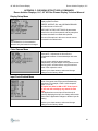
Digital DVI Menu
The digital DVI input is the highest quality input available. The reason for this quality is that
the video signal is not an analog signal, which requires conversion to digital. Therefore the
signal is coming from the source in digital format and is processed in the HD DVC as a
digital signal and displayed in a digital format. The digital DVI connection to the HD DVC is
shared with the analog RGB input. The application can use one or the other but never both
at the same time.
The digital DVI input is to control the appearance of
the digital DVI input. “NONE” on the first line will be
replaced with the resolution being provided by the
source. If changes are made here and the settings
saved, a star (*) will appear next to the resolution
indicating a saved setup.
Use the up or down arrows to select and change
settings from the factory default.
Digital DVI Source Setup Menu
The source setup menu for the digital DVI input
provides only a color space control. RGB is the factory
default based on the input. Other options are YUV SD
and YUV HD.
Use the up or down arrows to select and change
settings from the factory default.
Analog RGB Menu
The analog RGB input is primarily used for computer
generated graphics such as being used as a computer
display.
The analog RGB input connection is shared with the
digital DVI input connector. The application can not
have both connected at the same time. The factory
defaults provide the optimum display of analog RGB
signals. However, the application can change them
from the factory defaults for their specific preference.
Use the up or down arrows to select and change
settings from the factory default.
32
42” HD Gas Plasma Display
Rosen Aviation Displays, LLC
APPENDIX C: OSD MENU STRUCTURE & COMMANDS
Rosen Aviation Displays, LLC, 42" HD Gas Plasma Display Technical Manual
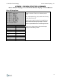
Analog RGB Source Setup Menu
In the analog RGB mode, the HD DVC assigns the
source setup values and it is not recommended that
the application change these settings. However, the
application can change them to provide for a shift in
the display as necessary.
Use the up or down arrows to select and change
settings from the factory default.
YPbPr (Component)
There are 2 separate YPbPr or component inputs. This type of input provides the best
analog video signal.
YPbPr.1 Menu
The YPbPr.1 input uses the 3 RCA style connectors
incorporated in the video bundle. This input is for use
with any interlaced or non-interlaced source.
Resolutions are from 480p/i to 1080i. See the
standard resolutions section of this manual for a
complete list of acceptable resolutions.
“None” on the menu’s first line will be replaced by the
resolution that has been detected. If a star (*) is next
to the resolution, the settings have been changed in
some way and saved.
Use the up or down arrows to select and change
settings from the factory default.
YPbPr.1 Source Setup Menu
The source setup for YPbPr.1 input look the same as
the S-Video and the composite inputs but do not
interact with each other. Each of them is separate so
that the application can set up 2 totally different
sources for these inputs. The YPbPr.1 input uses
only the CAV portion of this menu. There is no
need to change the top 5 menu selections in that
they have no effect on this input.
Use the up or down arrows to select and change
settings from the factory default.
33
42” HD Gas Plasma Display
Rosen Aviation Displays, LLC
APPENDIX C: OSD MENU STRUCTURE & COMMANDS
Rosen Aviation Displays, LLC, 42" HD Gas Plasma Display Technical Manual
YPbPr.2 Menu
The YPbPr.2 input uses the 3 BNC-style connector on
the HD DVC. You can supply a signal from 480p or
720p including 540p on this input. This input will not
accept the interlaced style input such as 1080i.
“None” on the menu’s first line will be replaced by the
resolution that has been detected. If a star (*) is next
to the resolution, the settings have been changed in
some way saved.
Use the up or down arrows to select and change
settings from the factory default.
YPbPr.2 Source Setup Menu
The source setup for YPbPr.2 input looks the same as
the analog RGB input, but does not interact with it.
Each of them is separate so that the application can
set up 2 totally different sources for these inputs. The
color space can be set to YUV HD, YUV SD, or RGB.
The system will detect what is best and the application
should not have to change the setting.
Use the up or down arrows to select and change
settings from the factory default.
Gain Control Menu
Use the Gain control menu to adjust the input gain
only if the automatic functions are not satisfactory to
the end application. In most cases, the application
should not have to interact with this menu.
Use the up or down arrows to select and change
settings from the factory default.
34
42” HD Gas Plasma Display
Rosen Aviation Displays, LLC
APPENDIX C: OSD MENU STRUCTURE & COMMANDS
Rosen Aviation Displays, LLC, 42" HD Gas Plasma Display Technical Manual
PIP Control Menu
The Picture in Picture (PIP) control menu allows full flexibility in viewing 2 sources at the
same time. Keep in mind some limitations were noted under PIP Modes in the main text.
Choose a viewing source, such as S-Video, and then
move to enable and turn it on.
The PIP window appears. Position it as desired on
the screen and/or adjust the size. It is possible to
shape the picture by increasing only one dimension
of the window such as increasing the horizontal size
and not increasing the vertical size. If the application
changes the main screen source, the PIP settings will
not be saved. The only exception to this is when a
user invokes a PIP SWAP using the direct IR key
code or the RS232 command.
Use the up or down arrows to select and change
settings from the factory default.
FlexiScreen Menu
FlexiScreenTM is applicable to all input menus during a valid source. The FlexiScreenTM
format refers to the active picture size and position on the screen.
The FlexiScreen menu allows the application to
adjust the screen size so that the images fit the entire
screen or even go beyond the screen.
All of these attributes of the screen can be varied. The
ASPECT can be set to 16:9, 4:3 or 1:1. The source
(SRC) can be set to any number of preset dimensions
or can be set to custom as is indicated here.
If any of the dimensioning selections are changed, the
SRC automatically changes to custom. Below and left
is a list of preset SRC dimension names.
Preset SRC Formats:
Acadamy
Open Matte
Super 35
VistaVision
Panavision
Panavision
Technorama
Custom
Use the up or down arrows to select and change
settings from the factory default.
35
42” HD Gas Plasma Display
Rosen Aviation Displays, LLC
APPENDIX C: OSD MENU STRUCTURE & COMMANDS
Rosen Aviation Displays, LLC, 42" HD Gas Plasma Display Technical Manual
Display Setup Menu
Use the display setup menu to customize the way the
display system functions.
FREEZE, INSTANT ON, and OSD BACKGROUND
can either be set to ON or OFF.
RESTORE FACTORY SETTINGS: All parameters
stored in the unit will be replaced, and any setup that
has been saved will be erased and replaced.
Note:
PSI VERSION is for documentation
reference only and cannot be changed.
The rest of the options in this menu are sub menus
discussed in the tables below.
Color Gamma Menu
The color gamma menu is used to adjust color
temperature. Adjustments in this menu are
complicated because of interrelationships with other
menus.
The red, green and blue gamma settings
independently vary the shapes of their gamma curves.
The red, green, and blue factors vary the maximum
levels of the respective colors.
Use the up or down arrows to select and change
settings from the factory default.
Input Ports Enabled Menu
Use this menu to turn any particular input on or off.
Some of the inputs can not be used simultaneously
with others. For example, YPbPr.1 with composite
inputs Y, R, or W.
All inputs can either be ON or OFF. If the input is
off, the unit will not display any menus for that
input.
If the application turns an input off and the unit is
currently displaying that input, the change will not take
effect until the application changes to another input for
viewing.
Use the up or down arrows to select and change
settings from the factory default.
36
42” HD Gas Plasma Display
Rosen Aviation Displays, LLC
APPENDIX C: OSD MENU STRUCTURE & COMMANDS
Rosen Aviation Displays, LLC, 42" HD Gas Plasma Display Technical Manual
Direct IR Setup Menu
Use this menu to setup one touch direct access to a
menu, or selection of an input, or discrete power
on/off.
Each of the number keys, (0–9) can be set to do any
function listed below left.
These functions make it easier for the application to
switch functions without going through the menus.
Use the right and left arrow to scroll through choices.
Function or Input Selections:
Power off
Power on
freeze
direct IR
Disp Prop
Ports
Gamma
None
Analog RGB
Digital DVI
Composite
Composite.Y
Composite.R
Composite.W
YPbPr.1
YPbPr.2
S Video
S Video.A
PIP Toggle
PIP Swap
Flexiscreen.
Use the up or down arrows to select and change
settings from the factory default.
37
42” HD Gas Plasma Display
Rosen Aviation Displays, LLC
APPENDIX D: CONFIGURATION AND PERFORMANCE OVERVIEW
Rosen Aviation Displays, LLC, 42" HD Gas Plasma Display Technical Manual
Specifications
Screen Size
42” diagonal;
36.3” (w) x 20.6” (h)
Resolution
1024(h) x 1024(v) color pixels
Size
39.5”(w) x 23.8”(h) x 3.25”(d)
Pixel pitch
0.90mm x 0.51mm
Viewing Angle 160 degrees omnidirectional
Color Depth 16.77 million video colors
User Interfaces
STV Inputs
(NTSC, PAL): Component,
S-Video, Composite (Cvs)
PC Inputs
(Analog RGB and DVI): VGA, WVGA, 480p, XGA, WXGA, SVGA, 720p (60HZ)
HDTV Inputs 480p, 720p, 1080i/540p
User Controls Hand held IR remote control to OSD, RS-232
PIP (Multiple Scenario)
Scenarios
Adjustments
HDTV with STV or PC
STV with HDTV or PC
PC with STV or HDTV
Zoom, Pan and Transparency
Picture by Picture
Real Time Digital Signal Processing
Line Doubler Motion Adaptive Deinterlacing
3:2/2:2 Pull Down
Scaler
Linear and Anamorphic
Filters
2/4 Comb, Anti-flicker, Sharpness
Electrical and Environmental
AC Power
85 to 264 VAC
400 Hz
3 A average @ 110 VAC
Temperature -20 to +70 C non-operating
-5 to +50 C operating
Moisture
20% to 90% RH
Non-condensing
EMC
FCC Part 15 Compliance
Broadband IR compatible
Safety
CSA/UL-1950 Compliance
Shock
20 G x 11ms in x,y
10 G x 11ms in z
Vibration
10 to 55 Hz, 2 G peak in x,y
1 G peak in z
Altitude
9,500 feet, nominal
38
42” HD Gas Plasma Display
Rosen Aviation Displays, LLC
APPENDIX D: CONFIGURATION AND PERFORMANCE OVERVIEW
Rosen Aviation Displays, LLC, 42" HD Gas Plasma Display Technical Manual
Mechanical
All metal packaging
Textured black exterior paint
Notes to Specifications:
Corrosive Environments:
Non-operating unit exteriors – do not expose for prolonged periods to ocean spray,
rain or moisture.
Unit interiors – do not allow water or other liquids inside the units under any
conditions.
Operating unit exteriors – do not expose to ocean spray, rain or moisture.
Dust:
Unit interiors – do not allow dust to be blown or drawn into the units.
Unit exteriors – do not clean off dust with solvents stronger than Isopropyl Alcohol.
39
42” HD Gas Plasma Display
Rosen Aviation Displays, LLC
APPENDIX E: Definition of Terms
Rosen Aviation Displays, LLC, 42" HD Gas Plasma Display Technical Manual
HD
HDTV
DVD
OSD
IR
PIP
RGBHV
VESA
HD-DSS
FCC
CE
CSA
UL
DVI
VGA
YPrPb
CAV
High Definition
High Definition Television
Digital Versatile Disk
On Screen Display
Infrared Universal Remote Control
Picture In Picture
Red Green Blue Horizontal Vertical
Video Electronics Standards Association
High Definition Digital Satellite Service
Federal Communications Committee
Conformity European
Canadian Standards Association
Underwriter’s Laboratory
Digital Visual Interface
Video Graphics Adapter
Component Video
Component Analog Video
40
42” HD Gas Plasma Display
Rosen Aviation Displays, LLC
WARRANTY EXCLUSIONS
No other warranty is expressed or implied, as to the product purchased, and under no
circumstances shall the manufacturer or manufacturer’s representatives be liable for any
liability, claim, loss, damage, expense or injury of any nature, or any direct, indirect, special,
incidental, or consequential damages however caused and on any theory of liability in
connection with or resulting from the resale or use of the products.
No other warranties, whether express, implied or statutory, are made or created by the
purchase of the product; the implied warranties of merchantability and/or fitness for a
particular purpose are expressly excluded.
As applicable, the reseller, the installer, and the user agree to indemnify and hold the
manufacturer and its representatives harmless from any claim arising for any warranty
assumed, made or implied by the reseller, the installer, or the user to the extent that it
exceeds or differs from the warranty offered herein.
The maximum liability of the manufacturer and its representatives to any person or entity
arising out of or in connection with any sale or use of the products, whether such liability
arises from any claim based upon contract, warranty, tort or otherwise, shall in no case
exceed the actual amount paid for the products, for value as delivered to their respective
distribution tiers. In no event will the original manufacturer be liable for costs of procurement
of substitute goods or services.
Product warranty will be void and null when products are subjected to corrosion or other
excesses of the product specifications, shipped in non-qualified containers, any markings
are altered, obliterated or removed, or any unauthorized disassembly and
reassembly/integration of product occurs. Removal of the front bezel is strictly prohibited.
Mounting the unit in any orientation with installer/user supplied mounting hardware is totally
the installer/user’s responsibility and liability.
41
42” HD Gas Plasma Display
Rosen Aviation Displays, LLC
OUTLINE DRAWINGS
Scope
The following drawing established the package outline of the 42” HD Gas Plasma Display.
General
Interpret this drawing in accordance with MIL-STD-100.
All dimensions are in inches followed by the equivalent in millimeters placed in brackets
[mm]. Do not scale this drawing.
Configuration
• Power Input: 115V AC via J1
• Data Inputs:
Optional NTSC Antenna Input via J2
S-Video Input via J5
Component Video via J6, J7, J8
Digital Video + Analog RGB Input via J9
Serial Data via J10
S-Video + Component Analog Video, or 3X Composite Video via J4, using
Video Bundle Cable
• Outputs:
Optional DC Power Output via J11
Optional IR Remote Output via J1
• Standard Case Color: Black
Mounting Requirements
Mount Unit with # 1/4 x 20 with Threaded Holes on Rear of Unit.
Allow at Least One Inch Clearance Above and Below the Unit for Ventilation.
SYM
J1
J2
J3
J4
J5
J6
J7
J8
J9
J10
J11
TYPE
IEC-320
F-Connector
Stereo Phone Jack
8-Pin DIN
4-Pin DIN
BNC
BNC
BNC
DVI
RJ-45
2mm Power Jack
FUNCTION
AC Power Input
Unused
IR Remote Out (optional)
S-Video (2) / CAV (2). CVS (1) (2) (3)
S-Video
Pb
Pr
Y
DVI/RGB
RS-232
12V DC Out (optional)
42
42” HD Gas Plasma Display
Rosen Aviation Displays, LLC
43
42” HD Gas Plasma Display
Rosen Aviation Displays, LLC
J2 is not used
44
42” HD Gas Plasma Display
Rosen Aviation Displays, LLC
Rosen Aviation Displays, LLC
www.rosenaviation.com
PH: (888) 668-4955
Thank you for your order
www.rosenaviation.com
Document Number 9002570, Rev A
1