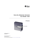
1
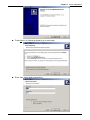
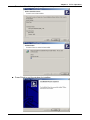
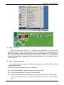
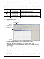
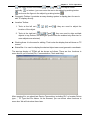
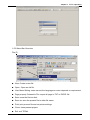
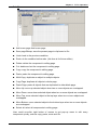
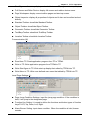
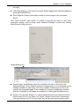
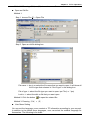
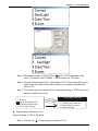
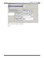
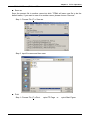
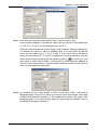
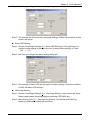
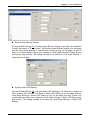
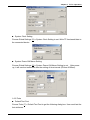
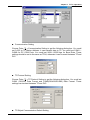
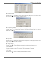
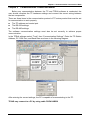
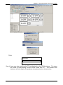
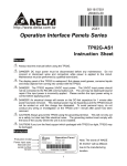
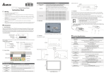
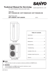
Table of Contents Chapter 1 TPEdit Operation............................................................................ 1-1 1-1 Hardware requirement ........................................................................ 1-1 1-2 Installation........................................................................................... 1-1 1-3 Basic Introduction ............................................................................... 1-4 1-4 Skills for mouse operation................................................................... 1-4 1-5 TPEdit Software Window .................................................................... 1-5 1-5-1 Explanation.................................................................................................... 1-5 1-5-2 Menu Bar Overview....................................................................................... 1-7 1-6 TPEdit Software Explanation in Detail .............................................. 1-14 1-6-1 File .............................................................................................................. 1-14 1-6-2 Edit .............................................................................................................. 1-23 1-6-3 Compile ....................................................................................................... 1-24 1-6-4 Objects Function Explanation...................................................................... 1-25 1-6-5 View............................................................................................................. 1-47 1-6-6 Communication ........................................................................................... 1-49 1-6-7 Local Page Settings .................................................................................... 1-50 1-6-8 Global Settings ............................................................................................ 1-55 1-6-9 Tools............................................................................................................ 1-57 1-6-10 Windows.................................................................................................... 1-60 1-6-11 Help ........................................................................................................... 1-60 Chapter 2 Communication Connection Mode ................................................. 2-1 Chapter 3 Examples ....................................................................................... 3-1 DELTA ELECTRONICS, INC. ALL RIGHTS RESERVED i Chapter 1 TPEdit Operation Chapter 1 TPEdit Operation 1.1 Hardware requirement Operation system requirement for installing TPEdit should be: Items Operation system CPU Memory Hard disk capacity Display resolution Mouse Printer RS-232 1.2 System requirement Windows 95/98/2000/NT/ME/XP Pentium 90 or above 16MB or above (32MB and above is recommended) 20MB or above 640x480, 16 colors and above Compatible with Windows Compatible with Windows At least one Com Port to connect to TP02G/04G Installation ■ Start-up Windows ■ Put the TPEdit software CD into disk ■ Press【Start】to select Run ■ Select the installation disk and directory to save. ■ Press Next> for following steps to go to next step 1-1 Chapter 1 TPEdit Operation ■ Press Next> for following steps to go to next step ■ Enter user name and organization. 1-2 Chapter 1 TPEdit Operation ■ Press Install for following steps to go to next step ■ Press Finish to end the window for installing. 1-3 Chapter 1 TPEdit Operation After finishing installing, user can execute TPEdit from windows> start. 1.3 Basic Introduction TPEdit is the program editor for TP series use in WINDOWS. You can see the design result on the screen immediately by concept of “What You See is What You Get” that TPEdit adopts. What you see on the screen is what display on TP. TPEdit uses object-oriented method to reach drag edition. In this way, you can move the components to anywhere and change shapes and sizes by using mouse. It is very easy for you to use this software. 1.4 Skills for Mouse Operation In the window, you can operate with either keyboard or mouse. But it will be easier to operate with mouse. There are four main operation functions in Windows: ■ One click left-button: to select function or component item. ■ Double-click left-button: to enter or execute the item. ■ Drag: press and hold on the left button to drag the mouse to move or adjust size. Once you release the button, the operation is finished. It is used to move or adjust size. 1-4 Chapter 1 TPEdit Operation ■ One click right button: it will display a pop-up menu of editing operation for you to select. It is usually to show mouse pointer on the screen to let you know where the position you are. There are many shapes of mouse to mean the different situation. You can know the edition status by the mouse pointer. Mouse Pointer Name Functions Arrow pointer The position where the mouse is. 、 Resize pointer It will display on the border of windows or object when adjusting size. ¨ Cross pointer It will display when opening object or drawing. I I pointer It will display when editing text. 1.5 TPEdit Software Window 1-5-1 Explanation Display name bar Menu bar Standard Toolbar Object Toolbar Text/Bmp Toolbar Geometric Toolbar Location Toolbar Working area Status Bar ■ Display Name Bar: display the present file name and file directory. ■ Menu Bar: There are 11 functions (File, Edit, Compile, Object, View, Communication, Local Page Setting, Global Setting, Tools, Windows and Help) in the menu bar. ■ Standard Toolbar: you can click the button what you want to execute directly with mouse. It is very easy for those users that are not familiar with computer to operate. ■ Object Toolbar: you can click the button what you want to execute directly with mouse. ■ Text/Bmp Toolbar: it lets you precisely align the text and figures in the object to left 1-5 Chapter 1 TPEdit Operation , the object center horizontally vertically , right , top , the object center or bottom. (you can move the text in the object by pushing button and move the figure in the object by pushing button ) ■ Geometric Toolbar: it provides an easy drawing system in display plan for user to edit TP display directly. ■ Location Toolbar 1. Tools at the left set ( , , and ): they are used to adjust the location of the object. 2. Tools at the right set ( , , and ): they are used to align multiple objects to top, bottom, left and right. (these tools are enabled only when two or more objects are selected) ■ Working Area: it is the area for editing. That is also the display that will show on TP screen. ■ Status Bar: it is used to display the desired object name and geometric coordinate. The start-up display of TPEdit will be shown as follows. There are four functions in menu bar for you to select(File, Communication, Tools and Help). After opening file, you should set Device Type setting, including PLC or Inverter Drives type…, TP Type and File Name. At the moment, you can select other functions in menu bar. We will introduce them later. 1-6 Chapter 1 TPEdit Operation 1-5-2 Menu Bar Overview File (F) ■ New: Create a new file. ■ Open : Open an old file. ■ User Menu Setting: users can set the languages or menu depends on requirement. ■ Page property Outward to File: export all page to TXT or EXCEL file. ■ Save: save the file into disk. ■ Save as: save the present file to other file name. ■ Print: print present file and set printer settings. ■ Close: close present project. ■ Exit: exit TPEdit. 1-7 Chapter 1 TPEdit Operation Edit (E) ■ Add a new page: Add a new page ■ Save page Bitmap: save the present page to clip board or file. ■ Undo: back to the previous condition. ■ Redo: do the condition before redo. (this item is for future edition) ■ Delete: delete the component in editing page. ■ Cut: delete and cut the component in editing page. ■ Copy: copy the component in editing page. ■ Paste: paste the component to editing page. ■ Multi-Copy: duplicate an object to multiple objects. ■ Copy Page: duplicate all objects in whole page. ■ Paste Page: paste all objects that are duplicated to other blank page. ■ Move Up: move up selected object when two or more objects are overlapped. ■ Move Down: move down selected object when two or more objects are overlapped. ■ Move Top: move selected object to the top layer when two or more objects are overlapped. ■ Move Bottom: move selected object to the bottom layer when two or more objects are overlapped. ■ Select all: select all components in editing page. User could one-click right button of mouse to get pop-up menu to edit every component quickly, such as copy, paste, move and etc. 1-8 Chapter 1 TPEdit Operation Compile (C) ■ Compile: to compile the finished page to download to TP. Objects (O): ■ Static Text: edit text to shown on TP screen. 1-9 Chapter 1 TPEdit Operation ■ Read Out: TP reads PLC corresponding value of register to show on TP screen. ■ Indicator (16x16): There are two types 1.Indicator: read the corresponding contacts (ON or OFF). 2. Multi-state Indicator: reads the register data to show the corresponding indicator on TP screen. ■ Bitmap: it is used to edit static bitmap to be the background. Or it also could be used for TP to read the corresponding contacts (ON or OFF) or register data to show the corresponding dynamic bitmap on TP screen. ■ Scale: edit the scale that user needs to TP screen. ■ Progress Bar: TP reads the PLC corresponding data of register to convert to progress bar to show on TP screen. ■ Meter: TP reads PLC corresponding data of register to convert to circle meter to show on TP screen. ■ Message Display: TP reads PLC corresponding contacts (ON or OFF) or register data to display the corresponding message on TP screen. ■ Button: it will have a series of button type for you to choose. It will be easier to design PLC program. ■ Clock Display: TP reads time/week/date from internal RTC or PLC series to display on TP screen. ■ Multi-state Bitmap: TP reads the corresponding contacts (ON or OFF) or register data to show the corresponding user-defined figure or characters on TP screen. ■ Units: edit the unit that user needs on TP screen. ■ Numeric Input: you can use function key or instruction key to input figures. TP will transmit figures to the corresponding registers of PLC when pressing Enter. ■ Curve: TP reads a serial figure from PLC corresponding registers to convert to curve and display on TP screen. ■ X-Y Curve: TP reads a serial figure from PLC corresponding registers to convert to XY chart and display on TP screen. ■ Geometric Graphic: it is used to edit TP display. View (V): ■ Page Manager: manage the edited page. ■ TP Page: display edited TP page and switch between TP page and start-up display. 1-10 Chapter 1 TPEdit Operation ■ Start Figure: edit start-up display and switch between TP page and start-up display. ■ Full Screen and Refer Device: display full-screen and relative device name. ■ Page Workspace: display current edition pages and start-up screen. ■ Object Inspector: display all properties of objects and it also can be edited and set directly. ■ Standard Toolbar: show/hide Standard Toolbar. ■ Object Toolbar: show/hide Object Toolbar. ■ Geometric Toolbar: show/hide Geometric Toolbar. ■ Text/Bmp Toolbar: show/hide Text/Bmp Toolbar. ■ Location Toolbar: show/hide Location Toolbar. Communication (M) ■ Read from TP: Read application program from TP to TPEdit. ■ Write to TP: Write application program from TPEdit to TP. ■ Write Start figure to TP: Write start-up display that edited by TPEdit into TP. ■ Write Menu to TP: Write user-defined user menu that edited by TPEdit into TP. Local Page Settings (L): ■ Page Jump Condition Settings: input the jump page condition. If the condition is held, it will jump to the designated page. ■ Function Key Setting: it is used to define the functions and button types of function keys F0~F9, Up, Down, Left, Right. ■ Alarm Buzzer Setting: input alarm condition. When the condition is held, buzzer sounds. 1-11 Chapter 1 TPEdit Operation ■ Alarm LED Setting: input alarm condition. When the condition is held, alarm LED will light. ■ Hide Page Setting: users cannot see these hidden pages when browsing pages by pressing UP/DOWN key. ■ Write Page No. Setting: write page number of current page to the connected device. User could one-click right button of mouse to get pop-up menu to edit every component quickly, such as Page Jump Condition Settings, Function Key Setting, Alarm Buzzer Setting and etc. Global Settings (G): ■ System Page Jump Setting: when the conditions are held, it will jump to the designated page. This is used for system to change page. It is not necessary to set change condition for each page. Once the condition in each page is held, it will jump to the designated page. (if the conditions of system change page conflicts with the conditions of each page, the conditions of each page has high priority.) ■ System Function Key Setting: it is used to define the button type and functions of function keys F0~F9, Up, Down, Left, Right. It doesn’t need to set in each page. Once the function keys F0~F9 are used, they will be executed according to the 1-12 Chapter 1 TPEdit Operation definition of button type and functions. (if the function settings of system conflicts with the function settings of each page, the function setting of each page has high priority.) ■ System Alarm Buzzer Setting: to set system alarm condition. When the conditions are held, buzzer will sound. It doesn’t need to set condition in each page. Once the condition is held, buzzer will sound in any page. (if the system alarm condition conflicts with the alarm condition of each page, the alarm condition of each page has high priority. ■ System Alarm LED Setting: to input alarm condition. When the condition is held, TP alarm LED will light. It doesn’t need to input alarm condition in each page. (if the alarm condition conflicts with alarm condition of each page, the alarm condition of each page has high priority.) ■ System Clock Setting: write TP time/week/date to the connected device. ■ System Power ON Marco Setting: it is used to set the interval time (when it is to transmit instruction) and the connected device (the device that instruction needed to be transmitted) after power up. Tools (T): ■ Default Text Font: it is used to set the font attributes that used in TPEdit. ■ Communication Setting: it is used to set the communication format between PC and TP. ■ TP Protocol Setting: set the communication format of TP and monitor devices, including RS-232 COM1 and RS-485(RS-422) COM2. ■ TP Object Communication Default Setting: set the communication port and station number for all objects in TP to communicate. ■ Change Device Type: switch the device type that TP connects. ■ User-Level/Password Setting: set user level and password. ■ AutoSave setup: set time to auto save file, such as before compiler or when. ■ Function Key Setting: it is used to enable Up, Down key. ■ Page Size: it is used to set windows’ size. 1-13 Chapter 1 TPEdit Operation ■ Grid Settings: it is used to set using grid or not. Windows (W): ■ Tile Vertically: display edit page in vertical. ■ Tile Horizontally: display edit page in horizontal. ■ Cascade: display edit page in overlay. Help(H): ■ Version: display software version of TPEdit and relative information. ■ Help: provide electronic file of TPEdit user manual. Above is the basic introduction of TPEdit. We will explain the functions that used frequently for detail in the following. 1.6 TPEdit Software Explanation in Detail 1-6-1 File ■ Create a New File It is used to create a new file. Do one of the following: Method 1: Step 1. File (F) > New 1-14 Chapter 1 TPEdit Operation 5 last used files Step 2. Set Device type. Step 3. User can set PLC or Inverter Type, TP type and File Name in this dialog box. Step 4. You can use file name to record the function of program. For example, you can name ”Monitor Production Line” for the program that monitors the production line. Step 5. TPEdit document usually have extension .tpe. TPEdit will name your new file to be Tpe0. (the default name will be Tpe0.tpe, Tpe1.tpe……in order. The following is the window for creating new project. Method 2: Click the button to create a new file. 1-15 Chapter 1 TPEdit Operation Method 3: Pressing[Ctrl]+[N]to create a new file. ■ Open an Old file Method 1: Step 1. choose File (F) > Open File Step 2. Open an old file dialog box. File name Ö key in or select the file name that you want to open. It will show all the file type that selected in “file of type” in this dialog box. File of type Ö select the file type you want to open: tpe File (i.e. *.tpe) Look in Ö select the disk or file that you want open. Method 2: Click the button to open the existed file. Method 3: Pressing[Ctrl]+[O]. ■ User Menu Setting You can set the language, menu content or TP information according to your request. In addition to the default three languages, user can select the suitable language for themselves. The following is for detail: 1-16 Chapter 1 TPEdit Operation Step 1. Choose File (F) > User Menu Setting > PLC-TP04 and it will show 21 pages (User &Menu Setting-0 ~ User &Menu Setting-20) about user menu setting for you to set. Step 2. Choose File (F) > User Menu Setting > PLC-TP02 and it will show 41 pages (User &Menu Setting-0 ~ User &Menu Setting-40) about user menu setting for you to set. Step 3. You can set the language you need here. But you can’t modify the function definition and button size. Step 4. You just need to double-click the item you want to modify and it will show the dialog box for you to edit. 1-17 Chapter 1 TPEdit Operation PC in TP04 hardware main Step 5. After editing, press 1. D/L AP TP04 menu. The words “WAIT COMM…” will be shown on TP screen. Step 6. Choose Communication (M) > Write Menu to TP. This function just can be used under the mode of User Menu Setting. It is used to download the menu to TP. Step 7. To set language you should select 6. language setting in TP04 main menu and then press Enter to set. 5. Buzzer 6 . Language Settings 7. Password Settings 8. Start-up Display Language Settings ENTER 1. English 2. Traditional Chinese 3. Simplified Chinese 4. User-defined ■ Page property Outward to File Export all page to TXT or Excel file. Step 1. Choose File (F) > Page property Outward to File. 1-18 Chapter 1 TPEdit Operation Step 2. Choose the page that needed to export. 1-19 Chapter 1 TPEdit Operation Step 3. choose the file type you want to export (text file or Excel file) 1-20 Chapter 1 TPEdit Operation ■ Save It is used to save the present file into disk. Method 1: choose File(F) > Save to save with the original file name. Method 2: Click the button 1-21 Chapter 1 TPEdit Operation Method 3: Press[Ctrl]+[S]. ■ Save as Save the present file in another name into disk. TPEdit will save new file to be the default name, if you want to save it to another name, please choose “Save as”. Step 1. Choose File (F) > Save as. Step 2. input file name and then save. ■ Print Step 1. Choose File (F) >Print. >print TP Page or 1-22 >print Start Figure. Chapter 1 TPEdit Operation Step 2. You can check the print attribute you need in the following dialog box. Step 3. You can preview the print result. ■ Close Choose File (F) > Close. to close the present file. 1-23 Chapter 1 TPEdit Operation ■ Exit Choose File (F) > Exit or click at the right upper-corner. Please confirm to save or not before exit TPEdit. 1-6-2 Edit In addition to undo, cute and paste functions of TPEdit Method 1: Choose Edit (E) > ■ Add a New Page Choose Edit (E) > Add a New Page or click the button to add new page. ■ Save page Bitmap: Choose Edit (E) > Save page Bitmap to save the present page Bitmap to clipboard or file. ■ Undo, Redo: to back to the previous action or redo the action before execute “undo”. ■ The functions of delete, Cut, Copy, Paste, Multi-Copy, Copy Page, Paste Page, Move Up, Move Down, Move Top, Move Button and Select all: Delete: delete the component from editing page. Cut: delete and cut the component from editing page. Copy: copy the component from editing page. Paste: paste the component from editing page. Multi-Copy: duplicate an object to multiple objects. Copy Page: duplicate all objects in whole page. 1-24 Chapter 1 TPEdit Operation Paste Page: paste all objects that are duplicated to other blank page. Move Up: move up selected object when two or more objects are overlapped. Move Down: move down selected object when two or more objects are overlapped. Move Top: move selected object to the top layer when two or more objects are overlapped. Move Bottom: move selected object to the bottom layer when two or more objects are overlapped. Select all: select all components from editing page. Method 2: User could one-click right button of mouse to get pop-up menu to edit every component quickly, such as copy, paste, move and etc. 1-6-3 Compile Choose Compile (C) > Compile or click the button to compile application program to transmit to TP04. After compiling successfully, you will get the following dialog box. 1-25 Chapter 1 TPEdit Operation 1-6-4 Objects Function Explanation You could choose Object (O) or press ﹝ ALT ﹞ + ﹝ O ﹞ to set object. It is the management system for all objects. You need to open a page before using this function. ■ Static Text Step 1. Choose Object (O) > Static Text or click the button . At the moment, the mouse pointer will be cross pointer. You can press the left button of mouse, drag to the position you need and then release to get the text square. 1-26 Chapter 1 TPEdit Operation Step 2. Move the mouse to static text square and then double-click left button of mouse to get the following window. Step 3. You can input text and setting the font attributes (including frame setting, Align Text, Location setting and font type). Frame setting could be no frame single frame, double frames, bold frames, dotted line frames or spotted line frames. Align Text could be from left towards to right, from right towards to left, from up towards to down and from down towards to up. Location setting could be left side, right side or middle side. You could select the font you need by pressing the button “Font” and you will get the following dialog box. 1-27 Chapter 1 TPEdit Operation Step 4. After setting, you will get the static text. If it can’t show completely, you should enlarge the size of text square. Step 5. Choose View (V) > Object Inspector: display all properties of objects and it also can be edited and set directly. 1-28 Chapter 1 TPEdit Operation ■ Read Out Step 1. Choose Object (O) > Read Out or click the button At the moment, the mouse pointer will be cross pointer. You can press the left button of mouse, drag to the position you need and then release to get the Read Out Object. Step 2. Move the mouse to the Read Out Object and then double-click left button of mouse to get the following window. Step 3. Click reference device and you will get the following window. 1-29 Chapter 1 TPEdit Operation Step 4. In this dialog box, you could set device name to be T, C and D and device number to be 0~F. If your device name is AC driver, it doesn’t need to check device name. It will show symbol $ to mean AC driver absolute address. What you need is to input absolute address in device number. Step 5. You could set device name, value type, value length, position, integer number, decimal number, frame setting, font, blink and fill 0 into upper bit. Step 6. Value type could be unsigned, signed, hexadecimal, BCD code, ASCII code, Binary or Floating. Value length could be 16 bits or 32 bits. The position could be right side, left side and middle. Step 7. The digital numbers of integer and decimal according to the setting of display value number. For example, if the real value of timer T0 is 50 seconds, if you set integer number is 3 and decimal number is 0 and it will display 500. If you set 3 for integer number and 1 for decimal number and it will display 050.0. Step 8. The settings of frame could be no frame, double-line frame, bold frame and the font size could be 5X8, 8X8, 8X12 and 8X16. Step 9.You could choose to fill 0 in upper bit or not. For example, there are 6 integer numbers and 2 decimal numbers of a value. If you check to fill 0, the value 324836 will display to 003248.36. If you don’t check to fill 0, the value 324836 will display to 3248.36. Step 10. After setting, TP will read PLC corresponding reference device to show the value on TP screen. Step 11. Choose View (V) > Object Inspector: display all properties of objects and it also can be edited and set directly. 1-30 Chapter 1 TPEdit Operation ■ Indicator(16x16) There are two types for you to choose: Indicator: Choose Object (O) > Indicator(16x16) > Indicator or click the button to set. When TP reads the PLC corresponding contacts (ON or OFF), it will show the corresponding figure. Multi-state Indicator: choose Object (O) > Indicator(16x16) > Multi-state Indicator or click the button to set. Step 1. Choose Object (O) > Indicator(16x16) > Multi-state Indicator. If you set as the following dialog box, When the device value >= 300, current state is 0 and the bitmap will display . There are five indications from 0 to 4. Step 2. The settings of, Current state 0~4, bitmap set, set display sequence and device 1-31 Chapter 1 TPEdit Operation value >= range value setting. You could set the corresponding bitmap for the current state. Each current state has the corresponding range value, if device value >= range value and it will show the corresponding bitmap. For example, if current state 0 and range value is 300, current state 1 and range value is 500, when device value is between 300, 500 and it will show the corresponding bitmap of current state 0, if device value is large than 500, and it will show the corresponding bitmap of current state 1. But if device value is small than 300, it won’t display any bitmap due to no current state conforms to it. Step 3. Choose View (V) > Object Inspector: display all properties of objects and it also can be edited and set directly. Step 4. it is used to set the arrangement order of the state of the corresponding device (from max to min or from min to max) Step 5. Double click the input cell of device value >=Range value to get the pop-up dialog of all state table for user to set. Step 6. “Refer Value” can be used to calculate state range. ■ Bitmap You could choose static bitmap or dynamic bitmap. Static Bitmap: choose Object (O) > Bitmap > Static Bitmap or click the button . It will read the static bitmap to be the background of TP. It just can read the file with extension .bmp now. Step 1. Choose Object (O) > Bitmap > Static Bitmap and move the mouse to the editing area. At the moment, the mouse pointer will be cross pointer. Pressing the left button and hold on to drag, once you release the button the action will be finished. The component will be shown. Step 2. Moving the mouse on this component and double-click the left button. You will 1-32 Chapter 1 TPEdit Operation get the following open dialog box. Choosing the picture with BMP file you want to open, and then click Open to return and the picture you choose will display on the screen. Step 3. Choose View (V) > Object Inspector: display all properties of objects and it also can be edited and set directly. TPEdit has built-in Bitmaps (including button type and arrows) for users to use. The built-in Bitmaps are saved in C: Program File\ Delta\ Tpedit_1.08\ BmpGroup. 1-33 Chapter 1 TPEdit Operation Dynamic Bitmap: Choose Object (O) > Bitmap > dynamic bitmap or click the button . TP reads PLC the corresponding contacts (ON or OFF) or register data value will do comparison operation according to the corresponding base state. The setting bitmap will be displayed on the screen according to the operation result. (it you check bit, base state could be 0 or 1. If you check value, base state could be set to 255) Step 1. Choosing Object (O) > Bitmap > Dynamic Bitmap and then move the mouse to the editing area. At the moment, the mouse pointer will be cross pointer and you could press left button and hold on to drag. Once you release the button, the action will be finished and the component will be displayed. Step 2. You could move the mouse to this component and double-click the left button to get the following dialog box. Step 3. The settings of reference device, Total state, Current state, device value >= range value setting are the same as the Multi-state Indicator. The Total state could be set to 0~254. If you press BMP read, you will get the open dialog box. You could set the corresponding bitmap for the current state. Each Current state has the corresponding range value, if device value >= range value and it 1-34 Chapter 1 TPEdit Operation will show the corresponding bitmap. For example, if current state 0 and range value is 100, current state 1 and range value is 300, when device value is between 100, 300 and it will show the corresponding bitmap of current state 0, if device value is large than 300, and it will show the corresponding bitmap of current state 1. But if device value is small than 100, it won’t display any bitmap due to no current state conforms to it. Step 4. Choose View (V) > Object Inspector: display all properties of objects and it also can be edited and set directly. Step 5. it is used to set the arrangement order of the state of the corresponding device (from max to min or from min to max) Step 6. Double click the input cell of device value >=Range value to get the pop-up dialog of all state table for user to set. Step 7. “Refer Value” can be used to calculate state range. ■ Scale Step 1. Choose Object (O) > Scale or click the button 1-35 to get the following dialog. Chapter 1 TPEdit Operation Step 2. You could set scale position, progress direction, main scale, sub scale, Max. value, Min value, value length or font in the dialog box. Step 3. The graduation of scale could be face up, down, left or right. The progress direction could be Forward (increase from left to right or top to bottom), or reverse (increase from right to left or bottom to top). Step 4. Setting the precision of scale of main scale and sub scale. Step 5. The scale usually display with bar chart and that is very clear for user to see the value from the Progress Bar. Step 6. Choose View (V) > Object Inspector: display all properties of objects and it also can be edited and set directly. ■ Progress Bar Step 1. Choose Object (O) > Progress Bar or click the button dialog box. 1-36 to get the following Chapter 1 TPEdit Operation Step 2. You could set reference device, value type, value length, direct set, max., and min value in the dialog box. Step 3. direct set is used to set the direction for Progress Bar to increase and show on the TP screen. Step 4. Max. value and min. value are the range for value to display. Only the value between max. and min. value will be shown on the bar chart. Step 5. After setting, TP will read PLC corresponding register data and convert it to Progress Bar to show on TP screen. Step 6. Choose View (V) > Object Inspector: display all properties of objects and it also can be edited and set directly. ■ Meter Step 1. Choose Object (O) > Meter >circle meter or click the button to get the following dialog box. Step 2. You could set reference device, value type, integer number, decimal number, max. value, min. value, style, font, main scale and sub scale. Step 3. The style could be 300 or 360 degrees. It means a circle is 300 or 360 degrees. Step 4. After setting, TP will read the PLC corresponding register data and convert it to circle meter to show on TP screen. Step 5. Choose View (V) > Object Inspector: display all properties of objects and it also can be edited and set directly. 1-37 Chapter 1 TPEdit Operation ■ Message Display Step 1. Choose Object (O) > Message Display or click the button to get the following dialog box. The settings of reference device, Total state, Current state, device value >= range value setting are the same as the Dynamic Bitmap. The max. Total state is 255 (Value) or 2 (Bit). Step 2. TP will read the PLC corresponding contacts (ON or OFF) or register data and display the corresponding status on TP screen. The content of message could only be text and the text direction of LED message will be scrolls in a loop as follows: from right to left, from left to right, from top to bottom and from bottom to top. Step 3. Choose View (V) > Object Inspector: display all properties of objects and it also can be edited and set directly. Step 4. it is used to set the arrangement order of the state of the corresponding device (from max to min or from min to max) Step 5. Double click the input cell of device value >=Range value to get the pop-up dialog of all state table for user to set range value and edit message text. 1-38 Chapter 1 TPEdit Operation Step 6. “Refer Value” can be used to calculate state range. ■ Button TPEdit provides a series of button for user to use in every kind of occasion. That will save much time in designing PLC program. Choose Object (O) > Button or click the button to get the following dialog box. The following is the introduction for the buttons. The function of button includes user level and used with Tools (T) > User-Level/Password Setting. Choose View (V) > Object Inspector: display all properties of objects and it also can be edited and set directly. ON/OFF button: press this button and TP will send the contact signal to the PLC corresponding contact ON or OFF. There are 6 types of ON/OFF buttons. Set ON : Once you press this button and it will be always On. 1-39 Chapter 1 TPEdit Operation Reset : Once you press this button and it will be always Off. Rising Pulse: pressing this contact to send the signal of rising-edge to the PLC corresponding contact. Falling Pulse: pressing this contact one time to send the signal of falling-edge to the PLC corresponding contact. Toggle On/Off: pressing the contact one time, the contact will be On and it will be Off once you press the contact again. Momentary: the contact will be On when you press and hold on. Once you release the button, the contact is Off. Step 1. Choose Object (O) > Button and move the mouse to the editing area. At the moment, the mouse pointer will be cross pointer. You could press the mouse and hold on to drag, once you release the button the component will be displayed. Step 2. Double-click left button and you will get the following dialog box. Step 3. Pressing button at the right side of “Button Type” to select Set ON. Step 4. Pressing button at the right side of “Write” to select the reference device to write. And pressing button at the right side of “Read” to select the reference device to read. Step 5. Check Fun. Key and press to select one of F0~F9, Up, Down, Left, Right. Please notice that function keys F5~F9 should be used with Shift key. You should set it by yourself, if you don’t set it and you can’t control the button component. Step 6. User Level setting is used to protect this button. It should use with Tools (T) > User-Level/Password Setting. If you set password for the button, you should enter correct password before executing the button function. 1-40 Chapter 1 TPEdit Operation Step 7. Check “Call” and press to choose to call which reference device. And select “after writing” or “before writing” to Set or Reset. For example, if the reference device is Y3 and check “after writing” to “set”. It will inform Y3 to set after pressing the button. Step 8. Font is used to set the text on the button. Its size is usually set to 8X12. You could also select figure to put on button. You could select no frame, single frame, double frame, circle frame and hidden for the button. If you select hidden, the button won’t have any frame on the TP page but it still has the same function when executing. Step 9. If you press BMP read, you will get the open dialog box. You could set the corresponding bitmap for the current state. Step 10. After setting and press OK, the button will be used according to the setting unction. Multi-state: press this button and TP will send the signal to the PLC corresponding contact or register. The signal could be cycle through S0 S1 S2 … S0 or S0 … S2 S1 S0. The max. state could be 256 (VALUE), 16 (LSB) and 2 (BIT). Value: Press this button and TP will display built-in value on screen. You could use function key or common key to enter value. When pressing Enter, TP will send value to PLC corresponding register. 1-41 Chapter 1 TPEdit Operation Step 1. The setting steps are the same as ON/OFF button. There are some setting items are different in the dialog box. Step 2. The value length could be set to 16 bits or 32 bits. Value type could be unsigned , signed, hexadecimal and BCD. Step 3. If you set 3 for integer number and 2 for decimal number, the whole number will be displayed as 000.00. If you set 5000 for the maximum value, the maximum you could input is 050.00 due to there are 2 decimals. If you set 500 for the maximum value, the maximum you could input is 5.00. Step 4. After finishing input, press OK to enter and the button will be used by the function you set. Constant: Pressing this button and TP will send the constant setting to PLC corresponding register. 1-42 Chapter 1 TPEdit Operation Increase/Decrease: Pressing this button and TP will read register data from PLC and add or submit according to the settings. It will write the result to PLC corresponding register. If you set 10 for inc/dec and 1000 for up/down bound, it means it will increase/decrease 10 for each time you press the button. And the maximum you can increase/decrease is 1000. Page Jump: Pressing this button and TP will change to designate page. You can press to select or enter the page number directly. 1-43 Chapter 1 TPEdit Operation Password: There are functions of password setting and inform command in the dialog box. You could use password setting to protect this button. And you could check “call” to set to call the reference device to reset to set before writing or after writing. User can use “User level” to set the user priority. ■ Clock Display Step 1. Choose Object (O) > Clock Display or click the button directly and you will get the following dialog box. Step 2. Choose View (V) > Object Inspector: display all properties of objects and it also can be edited and set directly. 1-44 Chapter 1 TPEdit Operation Step 3. You can set time relative, font, frame set and Location set in the dialog box. Step 4. TP will read the value of time and date of REAL TIME CLOCK and display on TP screen directly. Step 5. You could select time of TP or time of PLC. Time of TP means the time you write into reference device and time of PLC means the time read the PLC time from register data. ■ Multi-state Bitmap Step 1. Choose Object (O) > Lamp Display or click the button to get the following dialog box. The settings are the same as dynamic figure. The addition setting is text input. It is used to input text and edit text. screen. Step 2. Choose View (V) > Object Inspector: display all properties of objects and it also can be edited and set directly. ■ Units Step 1. Choose Object (O) > Units or click the button following dialog box. 1-45 directly and you will get the Chapter 1 TPEdit Operation Step 2. You could set the Metrology type and Unit Name you need. Step 3. Choose View (V) > Object Inspector: display all properties of objects and it also can be edited and set directly. ■ Numeric Input You can use function key or instruction key to input figures. TP will transmit figures to the corresponding registers of PLC when pressing Enter. Step 1. Choose Object (O) > Numeric Input or click the button directly and you will get the following dialog box. The settings of reference device, Value Set, Limit Set, Outline Set, Call Set, User Level are the same as the Button Value Setting. Step 2. Choose View (V) > Object Inspector: display all properties of objects and it also can be edited and set directly. ■ Curve TP reads a serial figure from PLC corresponding registers to convert to curve to display on TP screen. Step 1. Choose Object (O) > Curve or click the button following dialog box. 1-46 directly and you will get the Chapter 1 TPEdit Operation Step 2. User designates D0 device and TP will use D0 content to be sampling points and 100 points max. Odd numbers will be a sets(D1, D3…) and even numbers will be the other sets (D2, D4…). User can use these two sets to draw two curves. Step 3. Choose View (V) > Object Inspector: display all properties of objects and it also can be edited and set directly. ■ X-Y Curve TP reads a serial figure from PLC corresponding registers to convert to XY chart to display on TP screen. Step 1. Choose Object (O) > X-Y Curve or click the button directly and you will get the following dialog box. Step 2. User designates D0 device and TP will use D0 content to be sampling points and 100 points max. The first point of corresponding XY can be composed of D1 and D2, the second point of corresponding XY can be composed of D3 and D4, and in this way, a XY chart can be drawn. Step 3. Choose View (V) > Object Inspector: display all properties of objects and it also can be edited and set directly. ■ Geometric Figure You could press the buttons to use geometric directly and press the buttons to draw the line. The following page is the result that did with these tools. 1-47 Chapter 1 TPEdit Operation 1-6-5 View ■ Page manager Choose View (V) > Page Manage and you will get the following dialog box. You could input page title to delete or add or insert that page or open all pages. ■ TP page Display TP page and change the page between TP page and start-up display. ■ Start-up display It is used to edit start-up display and change the pages between start-up display and TP display. ■ Full Screen and Refer Device: Display full-screen and relative device name. 1-48 Chapter 1 TPEdit Operation ■ Page Workspace Display current edition pages and start-up screen. One click right button: it will display a pop-up menu of editing operation for you to select(Add、Insert、Edit、Delete and Open All). ■ Object Inspector Display all properties of objects and it also can be edited and set directly. 1-49 Chapter 1 TPEdit Operation ■ Toolbar: including Standard Toolbar, Object Toolbar, Geometric Toolbar, Text/Bmp Toolbar and Location Toolbar. Show/Hide Toolbar 1-6-6 Communication ■ Read from TP Step 1. After editing, choose Communication (C) > Read from TP or click the button directly to read the program from TP04 to TPEdit. Step 2. After editing, press 1. U/L AP TP04 PC in TP04 hardware main menu. The words “WAIT COMM…” will be shown on TP screen. ■ Write to TP Step 1. After editing, Choose Communication (C) > Write to TP or click the button directly to write the program edited by TPEdit into TP04. Step 2. After editing, press 1. D/L AP TP04 PC in TP04 hardware main menu. The words “WAIT COMM…” will be shown on TP screen. ■ Write Start figure to TP Step 1. After editing, Choose Communication (C) > starting figure write in to edit start-up display to input to TP04. Step 2. After editing, press 1. D/L AP TP04 PC in TP04 hardware main menu. The words “WAIT COMM…” will be shown on TP screen. 1-50 Chapter 1 TPEdit Operation ■ Write Menu to TP Step 1. After editing, Choose Communication (C) > User Menu Write in to edit user menu to input to TP04. Step 2. After editing, press 1. D/L AP TP04 PC in TP04 hardware main menu. The words “WAIT COMM…” will be shown on TP screen. 1-6-7 Local Page Settings There are six functions (including Page Jump Condition Settings, Function Key Setting, Alarm Buzzer Setting, Alarm LED Setting, Hide Page Setting, and Write Page No. Setting) you can use. We will explain these six functions in the following. ■ Page Jump Condition Settings Step 1. Choose Local Page Settings (L) > Page Jump Condition Settings or click right mouse button directly in editing page and select “Page Jump Condition Settings” in pop-up menu, or Press[Ctrl]+[F1]. There are 20 sets max. Pop-up menu for edit function Working area Step 2. After clicking, it will show “Page Jump Condition Settings” dialog box. 1-51 Chapter 1 TPEdit Operation Step 3. Click reference device to input device name, device number and communication address. The devices’ name that you can set in this window are X, Y, M, S, D, C and T and the equipment no. are 0~9. Select the reference device (In the “Page Jump Condition Settings” dialog box, it is different to set Bit or Value in condition Set. If you set to Bit, the device name you can select are X, Y, M, S, C and T. If you set to Value, the device name you can select are T, C and D. In dialog box of device reference, you can check device name and select device name by clicking . If it is AC drive, you don’t need to check device name. It will show $ to mean absolute address of AC drive, input equipment no, communication address and then press Enter to return to jump page set dialog box. Step 4. In condition set, you could set Bit or Value. If you set it to Bit, it will jump to designate page. If you set it to Value, you need to input value length, value type, condition and operation condition. If the conditions are held, it will jump to the designate page. If you just edit one page, the jump page will display 0 due to the default first page is number 0. 1-52 Chapter 1 TPEdit Operation You can set the value length and value type that you need in value setting. Value length could be 16-bit or 32-bit. Value type could be unsigned or signed decimal, hexadecimal or BCD. Condition could be =, <, >, >=, <= or !=. Step 5. After finishing input, press “Add in” to add. The condition will display in the 1-53 Chapter 1 TPEdit Operation message window. You can press “Update” to update jump page condition or press “Delete”, “Delete All” to delete condition. Step 6. After setting, press “Close” to return to editing page. ■ Function Key Setting Step 1. Choose Local Page Settings (L) > Function Key Settings or click right button of mouse to get the pop-up menu to select function key settings, or Press[Ctrl] +[F2]. Step 2. And then you will get the following function key setting dialog box. Step 3. it is used to set button type of function key F0~F9, Up, Down, Left, Right. (you can refer to object setting.) Once you set a function key, you should press button “Set” to set. And if you want to clear a function key, you just need to select that function key and press “Clear” to clear or press “Clear All” to clear all. After setting, you can press “Close” to exit this dialog box. ■ Alarm Buzzer Setting Step 1. Choose Local Page Settings (L) > Alarm Buzzer Setting or click right button of mouse in editing page to get pop-up menu to select alarm setting, or Press [Ctrl]+[F3]. 1-54 Chapter 1 TPEdit Operation Step 2. And then you will get the alarm setting dialog box. Step 3. The settings are the same as jump page settings. When the condition is held, buzzer will sound. ■ Alarm LED Setting Step 1. Choose Local Page Settings (L) > Alarm LED Setting or click right button of mouse in editing page to get pop-up menu to select alarm setting, or Press [Ctrl]+[F4]. Step 2. And then you will get the alarm setting dialog box. Step 3. The settings of alarm LED are the same as alarm settings. Once the condition is held, the alarm LED will light. ■ Hide Page Setting Step 1. Choose Local Page Settings (L) > Hide Page Setting. users cannot see these hidden pages when browsing pages by pressing UP/DOWN key. Step 2. After clicking Tools (T) > Function Key Setting > Re-Define Up/Down Key, following confirmation dialog will be shown. 1-55 Chapter 1 TPEdit Operation Step 3. After pressing Yes, the function of “Hide Page Setting” will be invalided. ■ Write Page No. Setting Choose Local Page Settings (L) > Write Page No. Setting. Write page number of current page to the connected device. 1-6-8 Global Settings ■ System Page Jump Setting Choose Global Settings (G) > System Page Jump Setting to get the dialog box. You should notice that System Page Jump Setting is the condition of change page of all pages but the condition of change page in Local Page Settings menu is only for the editing page. If there is a conflict between these two conditions, Local Page Settings > Page Jump Setting has high priority. There are 20 sets max. The setting method is the same as Local Page Settings > Page Jump Setting. ■ System Function Key Setting Choose Global Settings (G) > System Function Key Setting to get the dialog box. System function key is for all pages and the function key in Local Page Settings > Function Key Setting is only for the page you edit. If there is a conflict between these two conditions, Local Page Settings > Function Key Setting has high priority. The 1-56 Chapter 1 TPEdit Operation setting method is the same as Local Page Settings > Function Key Setting. ■ System Alarm Buzzer Setting Choose Global Settings (G) > System Alarm Buzzer Setting to set. When the condition is held, the buzzer in TP will sound. The System Alarm Buzzer Setting is for all pages and the Local Page Settings > Alarm Buzzer Setting is only for the page you edit. If there is a conflict between these two conditions, Local Page Settings > Alarm Buzzer Setting has high priority. The setting method is the same as Local Page Settings > Alarm Buzzer Setting. ■ System Alarm LED Setting Choose Global Settings (G) > System Alarm LED Setting to set. When the condition is held, system LED will light. The System Alarm LED Setting is for all pages and the Local Page Settings > Alarm LED Setting is only for the page you edit. If there is a conflict between these two conditions, Local Page Settings > Alarm LED Setting has high priority. The setting method is the same as Local Page Settings > Alarm LED Setting. 1-57 Chapter 1 TPEdit Operation ■ System Clock Setting Choose Global Settings (G) > System Clock Setting to set. Write TP time/week/date to the connected device. ■ System Power ON Marco Setting Choose Global Settings (G) > System Power ON Marco Setting to set. After power up, it will send an instruction after the setting of time interval (500ms~2000ms). 1-6-9 Tools ■ Default Text Font Choose Tools (T) > Default Text Font to get the following dialog box. User could set the font attributes. 1-58 Chapter 1 TPEdit Operation ■ Communication Setting Choose Tools (T) > Communication Setting to get the following dialog box. You could set 0~255 to TP Station Address. It can transmit data to TP. You could set COM1 ~ COM8 for PC COM Ports. You could set 9600~115200 bps for Baud Rate. These settings should be set to the same as TP04, otherwise it can’t transmit between TP and PLC. ■ TP Protocol Setting Choose Tools (T) > TP Protocol Setting to get the following dialog box. You could set COM1 (RS-232) Data Format and COM2(RS-422/RS-485) Data Format. These settings can transmit between TP and PLC. ■ TP Object Communication Default Setting 1-59 Chapter 1 TPEdit Operation Choose Tools (T) > TP Object Communication Default Setting to get the following dialog box. Set the communication port and station number for all objects in TP to communicate.. ■ Change Device Type Choose Tools (T) > Change Device Type to get the following dialog box. It can change connected device type. For example, before changing PLC to SIEMENS S7-200 series, it needs to modify bit/value device one by one. ■ User-Level/Password Setting Choose Tools (T) > User-Level/Password Setting to get the following dialog box. If there is User Level setting, TP will execute password function according to User-Level/Password Setting. The higher user level and higher priority and it needs the same level or higher priority to operate. 1-60 Chapter 1 TPEdit Operation ■ AutoSave setup Choose Tools (T) > AutoSave setup to get the following dialog box. It can set the time for auto file save, such as before compiler or when. ■ Function Key Setting Choose Tools (T) > Function Key Setting > Re-Define Up/Down Key. it is used to enable Up, Down key. ■ Page Size Choose Tools (T) > Page Size (All Page Size or Page Size) to set page proportion. The setting could be 100%, 200% or 400%. ■ Frame Setting Choose Tools (T) > Frame Setting to use grid as coordinate reference or not. 1-6-10 Windows Choose Windows to select Tile Vertically, Tile Horizontally or Cascade. 1-6-11 Help Choose Help (H) > version to display TPEdit software version. 1-61 Chapter 1 TPEdit Operation Choose Help (H) > Help to get the help of TPEdit software. 1-62 Chapter 2 Communication Connection Mode Chapter 2 Communication Connection Mode Before any communication between the TP and TPEdit software is conducted, the user should complete the TP hardware settings and connect the correct wiring between the two components. There are three items in the communication protocol of TP series product that must be set for communication to work properly. ■ The TP address and control port. ■ The RS-232 settings. ■ The RS-485 settings. The software communication settings must also be set correctly to achieve proper communication. In the TPEdit software select “Tools” then “Communication Settings”. Enter the TP Station Address, PC COM Port, and Baud Rate as shown in the following diagram. After entering the correct settings, the PC is capable of communicating to the TP. TP04G may connect to a PC by using cable DVPACAB530 2-1 Chapter 2 Communication Connection Mode DVPACAB530 ON PC (RS-232) ON ELC-TP02G/04G(RS-232) 9 5 1 6 6 1 5 9 9 PIN D-SUB 9 PIN D-SUB PC COM Port 9 PIN D-SUB female 9 PIN D-SUB female Rx 2 3 Tx GND 5 5 GND Communication methods: Step 1. After creating a display program, the program should be compiled before downloading to the TP. Select “Compile” in the menu bar to complete this task. Any errors in programming will be displayed after this process. Step 2. On the TP, select the “Download TP04 PC.” Step 3. To execute the command in the menu bar, choose “Communication” then “Write to TP” and finally select “Yes” to confirm the download. The software and hardware will both display the progress during download as shown below. 2-2 Chapter 2 Communication Connection Mode TP04: RECEIVING… Step 4. Users may also read from the TP and display it on the TPEdit window. The steps are similar to Downloading, except choose “Read from TP”. The software and hardware will both display the progress during download as shown below. 2-3 Chapter 2 Communication Connection Mode TP04: TRANSFERING… 2-4 Chapter 3 Examples Chapter 3 Examples Example 1. Edit Start Figure Step 1. Open TPEdit to select File(F) to create new file. Then choose View(V)> Start Figure and it will escape Start Figure Step 2. In edition display, you can choose static text or static graphics. If you choose static graphics, the mouse pointer will become to cross pointer in the working area. At this time, you can press the left button of mouse and hold on to drag. After releasing the left button, will show on the edition display as shown in above figure. Step 3. To move mouse to this component and double-click the left button of mouse, you will get the window as shown in the following. 3-1 Chapter 3 Examples Step 4. In TP04G, choosing 1. download program TP04G show the words of “WAIT COMM…”. PC. On TP04 screen, it will Step 5. In TPEdit, choosing “Communication” > “Write Start figure to TP” and then press “Yes” for confirmation. It will start to download to TP and it will display the progress during download. Start figure can be downloaded without compiler. Step 6. In TP04G, choosing “4. TP04G SETUP” > “8. START-UP DISPLAY” > “2. USER DEFINE” as the following and you will finish the start-up display. 1. Download TP04G <-- PC 2. Upload TP04G --> PC 3. Copy TP04G <--> PC 4 . TP04G Settings 5. Execute Start-up Display 5. Buzzer 6. Language Settings 7. Password Settings 8 . Start-up Display ENTER 1. TP04G Settings 2. User-defined Note: You can set start-up display by yourself. But the picture must be monochromatic BMP file and the Max. size should be 128X64. If you want to add text on it, the picture should be smaller than 128X64 as shown in the following. Example 2. To use TP04 to connect to two PLC and control their output contacts ON/OFF. Step 1. Choose File(F) to create a new file. 3-2 Chapter 3 Examples Step 2. Model settings should be set as following: 1. Set Device Type: You should choose “DELTA PLC”, TP type: you should choose TP04G, File Name: you can name by yourself, here we name it “ Connection with two PLC” and then press “OK” to enter edit mode. Step 3. To choose ”Object(O)” and move mouse to working area. At this time, mouse pointer will be cross pointer. To press left button and hold on to drag and the component will show in window after you release the button. Step 4. Choose View (V) > Object Inspector: display all properties of objects and it also can be edited and set directly. Step 5. Double-click the left button of the mouse and you can see the following window. 3-3 Chapter 3 Examples Step 5. To click in the right side of button type and you can choose Button type. Step 6. To click besides “Write” and the window of “Device reference” will be shown as following. Here we set Y1 to control ON/OFF of Y1. That is very important to set the communication address. If the communication address of the first PLC is 1 and then set it to 1, the communication address of the second PLC is 2 then set it to 2. Each PLC has its communication address independently. Step 7. If you check the item of “Read” and press besides “Read”, it will also have the window of device reference. You can set the device name, number and communication address that you want to read and then press “OK” to return to the window. Step 8. If you check the item of “Function key” and press besides “Function key”, you will get the pop-up menu. You can set it by yourself to control button components. Step 9. You can set password to protect this component. Step 10. Button text is to set the text on the button. The font size is usually 8X12 and is also clear to display. You can also put the figure on the button. Step 11. To press “OK” after finishing setting and this button will be used for the setting functions. Step 12. Choose “Compile” > “Compile” to compile the edition page. Step 13. In TP04G, choose “1. download program TP04G 3-4 PC” to download and it will Chapter 3 Examples show “WAIT COMM…“. Step 14. In TPEdit, to choose “Communicate” > “Write to TP” and press “OK” to download program to TP04G. Step 15. To modify PLC communication address according to PLC parameter setting. Step 16. Using RS-485 to connect TP and PLC. The connection method is to connect negative terminal of RS-485 of two PLC to negative terminal of RS-485 of TP04G and connect positive terminal of RS-485 of two PLC to positive terminal of RS-485 of TP04G. Step 17.Then choosing “5. EXIT & RUN” in TP04 menu to RUN. The first PLC Communication address=1 Slave Workstation TP04G Master Workstation The second PLC Communication address =2 Slave Workstation The max. PLC numbers that TP04 can connect is less than 255 PLCs. Master TP connects to slave PLC in series with RS-485. In each PLC, you should give them a different communication address. The setting methods are the same as one-to-one connection but the difference is it needs to set PLC communication address in TPEdit. The first PLC Communication address=1 Slave Workstation TP04G Master Workstation The second PLC Communication address =2 Slave Workstation The N PLC Communication address =N Slave Workstation 3-5