1
33D-9-80_cover 09.7.16 13:46 ページ 1
2010
q Read this manual carefully before operating this vehicle.
q Il convient de lire attentivement ce manuel avant la première utilisation du véhicule.
q Bitte lesen Sie diese Bedienungsanleitung sorgfältig durch, bevor Sie das Fahrzeug in Betrieb nehmen.
YZ450F(Z)
2010
PRINTED ON RECYCLED PAPER
YAMAHA MOTOR CO., LTD.
2500 SHINGAI IWATA SHIZUOKA JAPAN
PRINTED IN JAPAN
2009.07—2.1 × 1 !
(E, F, G)
OWNER’S SERVICE MANUAL
MANUEL D’ATELIER DU
PROPRIETAIRE
FAHRER- UND
WARTUNGSHANDBUCH
YZ450F(Z)
33D-28199-80
33D-9-80_cover 09.7.16 13:46 ページ 2
Q Read this manual carefully before operating this vehicle. This manual should stay with this vehicle if it is sold.
Q Il convient de lire attentivement ce manuel avant la première utilisation du véhicule. Le manuel doit
être remis avec le véhicule en cas de vente de ce dernier.
Q Bitte lesen Sie diese Bedienungsanleitung sorgfältig durch, bevor Sie das Fahrzeug in Betrieb nehmen.
Diese Bedienungsanleitung muss, wenn das Fahrzeug verkauft wird, beim Fahrzeug verbleiben.
2010
Read this manual carefully before operating this vehicle.
OWNER’S SERVICE MANUAL
YZ450F(Z)
33D-28199-80-E0
YZ450F(Z)
OWNER'S SERVICE MANUAL
©2009 by Yamaha Motor Co., Ltd.
1st Edition, August 2009
All rights reserved. Any reprinting or
unauthorized use without the written
permission of Yamaha Motor Co., Ltd.
is expressly prohibited.
Printed in Japan
FOREWORD
INTRODUCTION
Congratulations on your purchase of
a Yamaha YZ series. This model is
the culmination of Yamaha's vast experience in the production of pacesetting racing machines. It represents
the highest grade of craftsmanship
and reliability that have made Yamaha a leader.
This manual explains operation, inspection, basic maintenance and tuning of your machine. If you have any
questions about this manual or your
machine, please contact your Yamaha dealer.
Yamaha continually seeks advancements in product design and quality.
Therefore, while this manual contains
the most current product information
available at the time of printing, there
may be minor discrepancies between
your machine and this manual. If you
have any questions concerning this
manual, please consult your Yamaha
dealer.
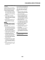
IMPORTANT MANUAL
INFORMATION
Particularly important information is
distinguished in this manual by the
following notations.
This is the safety alert symbol. It is
used to alert you to potential personal injury hazards. Obey all safety messages that follow this
symbol to avoid possible injury or
death.
A WARNING indicates a hazardous
situation which, if not avoided,
could result in death or serious injury.
A NOTICE indicates special precautions that must be taken to
avoid damage to the vehicle or other property.
A TIP provides key information to
make procedures easier or clearer.
SAFETY INFORMATION
PLEASE READ THIS MANUAL
CAREFULLY AND COMPLETELY
BEFORE OPERATING THIS MACHINE. DO NOT ATTEMPT TO OPERATE THIS MACHINE UNTIL YOU
HAVE ATTAINED A SATISFACTORY KNOWLEDGE OF ITS CONTROLS AND OPERATING
FEATURES AND UNTIL YOU HAVE
BEEN TRAINED IN SAFE AND
PROPER RIDING TECHNIQUES.
REGULAR INSPECTIONS AND
CAREFUL MAINTENANCE,
ALONG WITH GOOD RIDING
SKILLS, WILL ENSURE THAT YOU
SAFETY ENJOY THE CAPABILITIES AND THE RELIABILITY OF
THIS MACHINE.
THIS MACHINE IS DESIGNED
STRICTLY FOR COMPETITION
USE, ONLY ON A CLOSED
COURSE. It is illegal for this machine
to be operated on any public street,
road, or highway. Off-road use on
public lands may also be illegal.
Please check local regulations before
riding.
• THIS MACHINE IS TO BE OPERATED BY AN EXPERIENCED RIDER ONLY.
Do not attempt to operate this machine at maximum power until you
are totally familiar with its characteristics.
• THIS MACHINE IS DESIGNED TO
BE RIDDEN BY THE OPERATOR
ONLY.
Do not carry passengers on this
machine.
• ALWAYS WEAR PROTECTIVE
APPAREL.
When operating this machine, always wear an approved helmet with
goggles or a face shield. Also wear
heavy boots, gloves, and protective
clothing. Always wear proper fitting
clothing that will not be caught in
any of the moving parts or controls
of the machine.
• ALWAYS MAINTAIN YOUR MACHINE IN PROPER WORKING
ORDER.
For safety and reliability, the machine must be properly maintained.
Always perform the pre-operation
checks indicated in this manual.
Correcting a mechanical problem
before you ride may prevent an accident.
• GASOLINE IS HIGHLY FLAMMABLE.
Always turn off the engine while refueling. Take care to not spill any
gasoline on the engine or exhaust
system. Never refuel in the vicinity
of an open flame, or while smoking.
• GASOLINE CAN CAUSE INJURY.
If you should swallow some gasoline, inhale excess gasoline vapors,
or allow any gasoline to get into
your eyes, contact a doctor immediately. If any gasoline spills onto
your skin or clothing, immediately
wash skin areas with soap and water, and change your clothes.
• ONLY OPERATE THE MACHINE
IN AN AREA WITH ADEQUATE
VENTILATION.
Never start the engine or let it run
for any length of time in an enclosed
area. Exhaust fumes are poisonous. These fumes contain carbon
monoxide, which by itself is odorless and colorless. Carbon monoxide is a dangerous gas which can
cause unconsciousness or can be
lethal.
• PARK THE MACHINE CAREFULLY; TURN OFF THE ENGINE.
Always turn off the engine if you are
going to leave the machine. Do not
park the machine on a slope or soft
ground as it may fall over.
• THE ENGINE, EXHAUST PIPE,
MUFFLER, AND OIL TANK WILL
BE VERY HOT AFTER THE ENGINE HAS BEEN RUN.
Be careful not to touch them or to
allow any clothing item to contact
them during inspection or repair.
• PROPERLY SECURE THE MACHINE BEFORE TRANSPORTING
IT.
For safety, drain the gasoline from
the fuel tank before transporting the
vehicle.
F.I.M. MACHINE WEIGHTS
Weights of machines without fuel
The minimum weights for motocross
machines are:
for the class 125 cc:
minimum 88 kg (194 lb)
for the class 250 cc:
minimum 98 kg (216 lb)
for the class 500 cc:
minimum 102 kg (225 lb)
In modifying your machine (e.g., for
weight reduction), take note of the
above limits of weight.
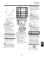
HOW TO USE THIS MANUAL
FINDING THE REQUIRED PAGE
1. This manual consists of eight
chapters; "General Information",
"Specifications", "Regular inspection and adjustments", "Engine",
"Chassis", "Fuel system", "Electrical" and "Tuning".
2. The table of contents is at the beginning of the manual. Look over
the general layout of the book before finding then required chapter
and item.
Bend the book at its edge, as
shown, to find the required fore
edge symbol mark and go to a
page for required item and description.
MANUAL FORMAT
All of the procedures in this manual
are organized in a sequential, stepby-step format. The information has
been complied to provide the mechanic with an easy to read, handy
reference that contains comprehensive explanations of all disassembly,
repair, assembly, and inspection operations.
In this revised format, the condition of
a faulty component will precede an
arrow symbol and the course of action required will follow the symbol,
e.g.,
• Bearings
Pitting/damage → Replace.
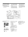
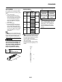
HOW TO READ DESCRIPTIONS
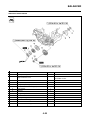
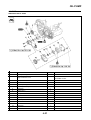
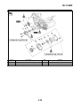
To help identify parts and clarify procedure steps, there are exploded diagrams at the start of each removal
and disassembly section.
1. An easy-to-see exploded diagram
"1" is provided for removal and
disassembly jobs.
3
2. Numbers "2" are given in the order of the jobs in the exploded diagram. A number that is enclosed
by a circle indicates a disassembly step.
3. An explanation of jobs and notes
is presented in an easy-to-read
way by the use of symbol marks
"3". The meanings of the symbol
marks are given on the next page.
4. A job instruction chart "4" accompanies the exploded diagram,
providing the order of jobs, names
of parts, notes in jobs, etc.
5. For jobs requiring more information, the step-by-step format supplements "5" are given in addition
to the exploded diagram and job
instruction chart.
5
1
2
4
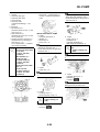
ILLUSTRATED SYMBOLS (Refer to
the illustration)
Illustrated symbols "1" to "7" are used
to identify the specifications appearing in the text.
1. With engine mounted
2. Filling fluid
3. Lubricant
4. Special tool
5. Tightening
6. Specified value, Service limit
7. Resistance (Ω), Voltage (V),
Electric current (A)
Illustrated symbols "8" to "13" in the
exploded diagrams indicate grade of
lubricant and location of lubrication
point.
8. Apply engine oil
9. Apply molybdenum disulfide oil
10. Apply brake fluid
11. Apply lightweight lithium-soap
base grease
12. Apply molybdenum disulfide
grease
13. Apply silicone grease
Illustrated symbols "14" to "15" in the
exploded diagrams indicate where to
apply a locking agent and where to install new parts.
14. Apply locking agent (LOCTITE®)
15. Use new one
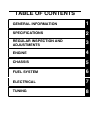
TABLE OF CONTENTS
GENERAL INFORMATION
1
SPECIFICATIONS
2
REGULAR INSPECTION AND
ADJUSTMENTS
3
ENGINE
4
CHASSIS
5
FUEL SYSTEM
6
ELECTRICAL
7
TUNING
8
CONTENTS
CHAPTER 1
GENERAL
INFORMATION
LOCATION OF
IMPORTANT LABELS ..... 1-1
DESCRIPTION ................. 1-5
CONSUMER
INFORMATION................. 1-6
FEATURES....................... 1-7
INCLUDED PARTS .......... 1-9
IMPORTANT
INFORMATION................. 1-9
HANDLING THE
ELECTRONIC PARTS ... 1-10
CHECKING OF
CONNECTION................ 1-10
SPECIAL TOOLS ........... 1-12
CONTROL
FUNCTIONS ................... 1-17
STARTING
AND BREAK-IN.............. 1-17
TORQUE-CHECK
POINTS........................... 1-19
CLEANING
AND STORAGE ............. 1-20
CHAPTER 2
SPECIFICATIONS
GENERAL
SPECIFICATIONS............ 2-1
MAINTENANCE
SPECIFICATIONS............ 2-3
TIGHTENING
TORQUES ...................... 2-11
LUBRICATION
DIAGRAMS .................... 2-17
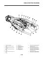
CABLE ROUTING
DIAGRAM....................... 2-18
CHAPTER 3
REGULAR
INSPECTION AND
ADJUSTMENTS
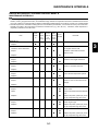
MAINTENANCE
INTERVALS...................... 3-1
PRE-OPERATION
INSPECTION
AND MAINTENANCE....... 3-5
ENGINE ............................ 3-6
CHASSIS ........................ 3-14
ELECTRICAL ................. 3-24
CHAPTER 4
ENGINE
SEAT
AND SIDE COVERS......... 4-1
EXHAUST PIPE
AND SILENCER ............... 4-3
RADIATOR ....................... 4-7
CAMSHAFTS.................. 4-10
CYLINDER HEAD........... 4-15
VALVES AND
VALVE SPRINGS ........... 4-19
CYLINDER
AND PISTON .................. 4-23
CLUTCH ......................... 4-27
OIL FILTER ELEMENT
AND WATER PUMP....... 4-31
BALANCER .................... 4-35
OIL PUMP....................... 4-37
KICK SHAFT
AND SHIFT SHAFT ........ 4-40
AC MAGNETO................ 4-45
ENGINE REMOVAL ....... 4-47
CRANKCASE
AND CRANKSHAFT ...... 4-52
TRANSMISSION,
SHIFT CAM
AND SHIFT FORK.......... 4-58
CHAPTER 5
CHASSIS
FRONT WHEEL
AND REAR WHEEL .........5-1
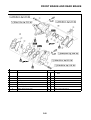
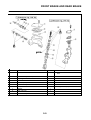
FRONT BRAKE
AND REAR BRAKE..........5-6
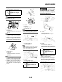
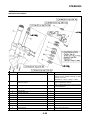
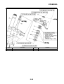
FRONT FORK.................5-16
HANDLEBAR..................5-24
STEERING ......................5-28
SWINGARM ....................5-32
REAR
SHOCK ABSORBER......5-37
CHAPTER 6
FUEL SYSTEM
FUEL TANK ......................6-1
THROTTLE BODY............6-4
CHAPTER 7
ELECTRICAL
ELECTRICAL
COMPONENTS AND
WIRING DIAGRAM ...........7-1
IGNITION SYSTEM...........7-3
THROTTLE POSITION
SENSOR SYSTEM ...........7-6
FUEL INJECTION
SYSTEM............................7-9
FUEL PUMP SYSTEM....7-35
ELECTRICAL
COMPONENTS...............7-36
CHAPTER 8
TUNING
CHASSIS ..........................8-1
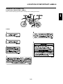
LOCATION OF IMPORTANT LABELS
GENERAL INFORMATION
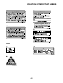
LOCATION OF IMPORTANT LABELS
Please read the following important labels carefully before operating this vehicle.
1
CANADA
1-1
LOCATION OF IMPORTANT LABELS
EUROPE
1-2
LOCATION OF IMPORTANT LABELS
AUS, NZ, ZA
1-3
LOCATION OF IMPORTANT LABELS
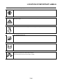
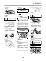
Familiarize yourself with the following pictograms and read the explanatory text.
Read Owner's service manual.
This unit contains high-pressure nitrogen gas. Mishandling can cause explosion. Do not incinerate,
puncture or open.
Turn off the main switch after riding to avoid draining the battery.
Use unleaded gasoline only.
Measure tire pressure when tires are cold.
Adjust tire pressure.
Improper tire pressure can cause loss of control.
Loss of control can result in severe injury or death.
1-4
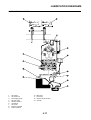
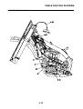
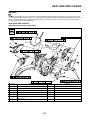
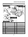
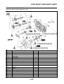
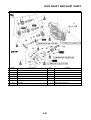
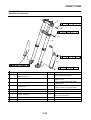
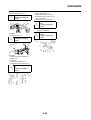
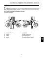
DESCRIPTION
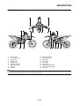
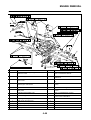
DESCRIPTION
1.
2.
3.
4.
5.
6.
7.
8.
9.
Clutch lever
Front brake lever
Throttle grip
Radiator cap
Fuel tank cap
Engine stop switch
Kickstarter crank
Fuel tank
Radiator
10.
11.
12.
13.
14.
15.
16.
17.
18.
Coolant drain bolt
Rear brake pedal
Valve joint
Air cleaner
Drive chain
Shift pedal
Oil level check window
Starter knob/idle screw
Front fork
• The machine you have purchased may differ slightly from those shown in the following.
• Designs and specifications are subject to change without notice.
1-5
CONSUMER INFORMATION
CONSUMER INFORMATION
There are two significant reasons for
knowing the serial number of your
machine:
1. When ordering parts, you can
give the number to your Yamaha
dealer for positive identification of
the model you own.
2. If your machine is stolen, the authorities will need the number to
search for and identify your machine.
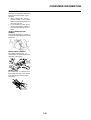
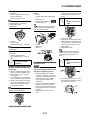
VEHICLE IDENTIFICATION
NUMBER
The vehicle identification number "1"
is stamped on the right of the steering
head pipe.
ENGINE SERIAL NUMBER
The engine serial number "1" is
stamped into the elevated part of the
right-side of the engine.
MODEL LABEL
The model label "1" is affixed to the
frame under the rider's seat. This information will be needed to order
spare parts.
1-6
FEATURES
FEATURES
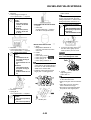
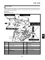
OUTLINE OF THE FI SYSTEM
The main function of a fuel supply system is to provide fuel to the combustion chamber at the optimum air-fuel ratio in accordance with the engine operating conditions and the atmospheric temperature. In the conventional carburetor system,
the air-fuel ratio of the mixture that is supplied to the combustionchamber is created by the volume of the intake air and the
fuel that is metered by the jet used in the respective carburetor.
Despite the same volume of intake air, the fuel volume requirement varies by the engine operating conditions,such as acceleration, deceleration, or operating under a heavy load. Carburetors that meter thefuel through the use of jets have been
provided with various auxiliary devices, so that an optimum air-fuel ratio can be achieved to accommodate the constant
changes in the operating conditions of the engine.
This model has adopted an electronically controlled fuel injection (FI) system, in place of the conventional carburetor system. This system can achieve an optimum air-fuel ratio required bythe engine at all times by using a microprocessor that
regulates the fuel injection volume according tothe engine operating conditions detected by various sensors.
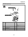
1.
2.
3.
4.
5.
6.
Fuel injector
Throttle position sensor
Intake air pressure sensor
ECU
Fuel pump
Intake air temperature sensor
7.
8.
9.
10.
11.
1-7
Atmospheric pressure sensor
Crankshaft position sensor
Coolant temperature sensor
Ignition coil
Condenser
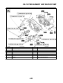
FEATURES
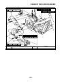
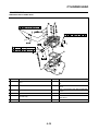
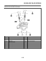
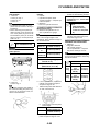
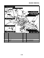
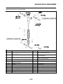
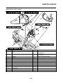
FI SYSTEM
The fuel pump delivers fuel to the fuel injector via the fuel filter. The pressure regulator maintains thefuel pressure that is
applied to the fuel injector at only 324 kPa (3.24 kgf/cm ² , 47.0 psi). Accordingly,when the energizing signal from the ECU
energizes the fuel injector, the fuel passage opens, causingthe fuel to be injected into the intake manifold only during the
time the passage remains open. Therefore, the longer the length of time the fuel injector is energized (injection duration),
the greater the volume of fuel that is supplied. Conversely, the shorter the length of time the fuel injector is energized (injection duration), the lesser the volume of fuel that is supplied.
The injection duration and the injection timing are controlled by the ECU. Signals that are input from the throttle position
sensor, coolant temperature sensor, atmospheric pressure sensor, lean angle sensor, crankshaft position sensor, intake
air pressure sensor and intake air temperature sensor enable the ECU to determine the injection duration. The injection
timing is determined through the signals from the crankshaft position sensor. As a result, the volume of fuel that is required
by the engine can be supplied at all times in accordance with the driving conditions.
4
C
1
3
5
A
11
2
10
B
9
8
7
6
1.
2.
3.
4.
5.
6.
7.
8.
9.
10.
Fuel pump
Fuel injector
ECU
Throttle position sensor
Coolant temperature sensor
Crankshaft position sensor
Intake air pressure sensor
Throttle body
Intake air temperature sensor
Air filter case
11. Atmospheric pressure sensor
A.
B.
C.
1-8
Fuel system
Intake system
Control system
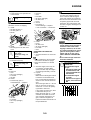
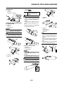
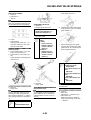
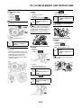
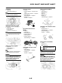
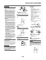
INCLUDED PARTS
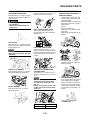
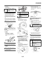
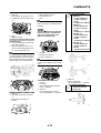
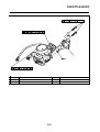
INCLUDED PARTS
DETACHABLE SIDESTAND
This sidestand "1" is used to support
only the machine when standing or
transporting it.
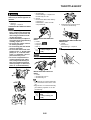
HANDLEBAR PROTECTOR
Install the handlebar protector "1" so
that the mark "a" face forward.
• Never apply additional force to
the sidestand.
• Remove this sidestand before
starting out.
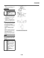
FUEL TANK HOLDING CABLE
The fuel tank holding cable "1" is
used to support the fuel tank during
maintenance.
VALVE JOINT
This valve joint "1" prevents fuel from
flowing out and is installed to the fuel
tank breather hose.
In this installation, make sure the
arrow faces the fuel tank and also
downward.
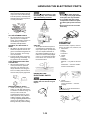
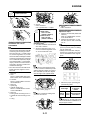
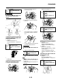
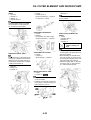
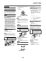
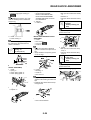
IMPORTANT INFORMATION
PREPARATION FOR REMOVAL
AND DISASSEMBLY
1. Remove all dirt, mud, dust, and
foreign material before removal
and disassembly.
• When washing the machine with
high pressured water, cover the
parts follows.
Air duct
Silencer exhaust port
Drain hole on the cylinder head
(right side)
Water pump housing hole at the
bottom
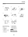
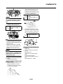
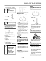
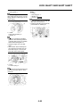
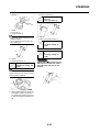
FUEL HOSE JOINT COVER
The fuel hose joint covers "1" are
used to prevent mud, dust, and other
foreign material from entering the fuel
pump when the fuel hose is disconnected.
2. Use proper tools and cleaning
equipment. Refer to "SPECIAL
TOOLS" section.
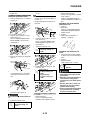
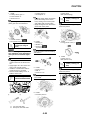
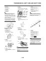
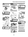
SPARK PLUG WRENCH
This spark plug wrench "1" is used to
remove and install the spark plug.
NIPPLE WRENCH
This nipple wrench "1" is used to
tighten the spoke.
COUPLER FOR CONNECTING
OPTIONAL PART
This coupler "1" is used for connection to an optional Power Tuner and
so on.
When no optional parts, etc. are
connected, connect the connection terminal to the original coupler "2".
Before removing the coupler, thoroughly wipe off any mud or water
stuck to it.
Part name
Part number
YZ Power Tuner
33D-859C0-10
The YZ Power Tuner is optional.
1-9
3. When disassembling the machine, keep mated parts together.
They include gears, cylinders,
pistons, and other mated parts
that have been "mated" through
normal wear. Mated parts must
be reused as an assembly or replaced.
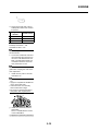
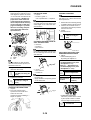
HANDLING THE ELECTRONIC PARTS
4. During the machine disassembly,
clean all parts and place them in
trays in the order of disassembly.
This will speed up assembly time
and help assure that all parts are
correctly reinstalled.
5. Keep away from fire.
ALL REPLACEMENT PARTS
1. We recommend to use Yamaha
genuine parts for all replacements. Use oil and/or grease recommended by Yamaha for
assembly and adjustment.
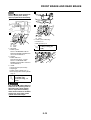
GASKETS, OIL SEALS AND ORINGS
1. All gaskets, oil seals, and O-rings
should be replaced when an engine is overhauled. All gasket surfaces, oil seal lips, and O-rings
must be cleaned.
2. Properly oil all mating parts and
bearings during reassembly. Apply grease to the oil seal lips.
LOCK WASHERS/PLATES AND
COTTER PINS
1. All lock washers/plates "1" and
cotter pins must be replaced
when they are removed. Lock
tab(s) should be bent along the
bolt or nut flat(s) after the bolt or
nut has been properly tightened.
Do not use compressed air to spin
the bearings dry. This causes damage to the bearing surfaces.
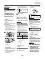
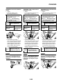
CIRCLIPS
1. All circlips should be inspected
carefully before reassembly. Always replace piston pin clips after
one use. Replace distorted circlips. When installing a circlip "1",
make sure that the sharp-edged
corner "2" is positioned opposite
to the thrust "3" it receives. See
the sectional view.
• Mankind has static electricity.
It`s voltage is very high and electronic parts are very sensitive.
• It is possible that inner small
components of electronic parts
are destroyed by static electricity.
• Do not touch and do not make
them dirty.
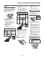
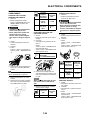
CHECKING OF
CONNECTION
Check the leads, couplers, and connectors for stains, rust, moisture, etc.
1. Disconnect:
• Lead
• Coupler
• Connector
2. Check:
• Lead
• Coupler
• Connector
Moisture → Dry with an air blower.
Rust/stains → Connect and disconnect several times.
HANDLING THE
ELECTRONIC PARTS
Electronic parts are very sensitive.
Handle with care and do not give
impact.
BEARINGS AND OIL SEALS
1. Install the bearing(s) "1" and oil
seal(s) "2" with their manufacturer's marks or numbers facing outward. (In other words, the
stamped letters must be on the
side exposed to view.) When installing oil seal(s), apply a light
coating of lightweight lithium base
grease to the seal lip(s). Oil the
bearings liberally when installing.
3. Check:
• All connections
Loose connection → Connect
properly.
If the pin "1" on the terminal is flattened, bend it up.
1-10
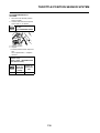
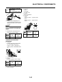
CHECKING OF CONNECTION
If the contact seems not good, pull
the terminal by hand and check its
condition.
1. Probe
2. Coupler
REMOVING THE QUICK
FASTENER
4.
•
•
•
Connect:
Lead
Coupler
Connector
Make sure all connections are tight.
5. Check:
• Continuity
(with the pocket tester)
Do not push the center pin with too
much force. Otherwise, the center
pin could be damaged.
To remove a quick fastener, push the
center pin in with a screwdriver, then
pull the fastener out.
Pocket tester:
90890-03112
Analog pocket tester:
YU-03112-C
• If there is no continuity, clean the
terminals.
• When checking the wire harness,
perform steps (1) to (5).
• As a quick remedy, use a contact
revitalizer available at most part
stores.
INSTALLING THE QUICK
FASTENER
To install a quick fastener, push its
center pin "a" back so that it protrudes
from the fastener head, then insert
the fastener and push the protruding
pin in until it is flush with the fastener
head.
When you check the voltage or electrical continuity, insert the measuring
probe from back side as you can insert from back side.
1-11
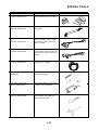
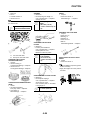
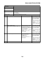
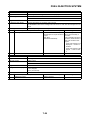
SPECIAL TOOLS
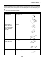
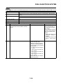
SPECIAL TOOLS
The proper special tools are necessary for complete and accurate tune-up and assembly. Using the correct special tool will
help prevent damage caused by the use of improper tools or improvised techniques. The shape and part number used for
the special tool differ by country, so two types are provided. Refer to the list provided to avoid errors when placing an order.
• For U.S.A. and Canada, use part number starting with "YM-", "YU-" or "ACC-".
• For others, use part number starting with "90890-".
Tool name/Part number
How to use
Dial gauge and stand
YU-3097, 90890-01252
Stand
YU-1256
These tools are used to check each
part for runout or bend.
Crankshaft installing tool
Crankshaft installing pot
YU-90050, 90890-01274
Crankshaft installing bolt
YU-90050, 90890-01275
Spacer (crankshaft installer)
YM-91044, 90890-04081
Adapter (M12)
YU-90063, 90890-01278
These tools are used to install the
crankshaft.
Piston pin puller set
YU-1304, 90890-01304
This tool is used to remove the piston pin.
Radiator cap tester
YU-24460-01, 90890-01325
Radiator cap tester adapter
YU-33984, 90890-01352
These tools are used for checking
the cooling system.
Steering nut wrench
YU-33975, 90890-01403
This tool is used when tighten the
steering ring nut to specification.
1-12
Illustration
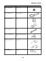
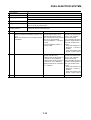
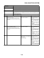
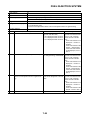
SPECIAL TOOLS
Tool name/Part number
How to use
Cap bolt wrench
YM-01500, 90890-01500
This tool is used to loosen or tighten
the base valve.
Cap bolt ring wrench
YM-01501, 90890-01501
This tool is used to loosen or tighten
the damper assembly.
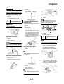
Fork seal driver
YM-A0948, 90890-01502
This tool is used when install the fork
oil seal.
Spoke nipple wrench
YM-01521, 90890-01521
This tool is used to tighten the
spoke.
Pocket tester
YU-03112-C, 90890-03112
Use this tool to inspect the coil resistance, output voltage and amperage.
Timing light
YM-33277-A, 90890-03141
This tool is necessary for checking
ignition timing.
Pressure gauge.
YU-03153, 90890-03153
This tool is used to measure the fuel
pressure.
1-13
Illustration
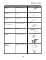
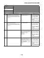
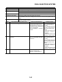
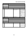
SPECIAL TOOLS
Tool name/Part number
How to use
FI diagnostic tool
YU-03182, 90890-03182
This tool is used to check the fault
codes and diagnose any problems.
Fuel pressure adapter
YM-03186, 90890-03186
This tool is used to attach the pressure gauge.
Test harness S-pressure sensor
(3P)
YU-03207, 90890-03207
This tool is connected between the
intake air pressure sensor and the
wire harness and is used to measure the voltage.
Test harness-speed sensor (3P)
YU-03208, 90890-03208
This tool is connected between the
throttle position sensor and the wire
harness and is used to measure the
voltage.
FI diagnostic tool sub-lead
YU-03212, 90890-03212
This tool is used to connect the FI diagnostic tool to a battery.
Valve guide remover & installer set
90890-04016
This tool is needed to remove and
install the valve guide.
Valve spring compressor
YM-4019, 90890-04019
This tool is needed to remove and
install the valve assemblies.
Clutch holding tool
YM-91042, 90890-04086
This tool is used to hold the clutch
when removing or installing the
clutch boss securing nut.
1-14
Illustration
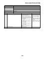
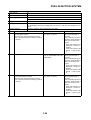
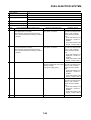
SPECIAL TOOLS
Tool name/Part number
How to use
Valve guide remover
5.5 mm (0.22 in)
YM-01122
This tool is needed to remove and
install the valve guide.
Valve guide installer
5.5 mm (0.22 in)
YM-04015
This tool is needed to install the
valve guide.
Valve guide reamer
5.5 mm (0.22 in)
YM-01196
This tool is needed to rebore the
new valve guide.
Valve spring compressor attachment
YM-04108, 90890-04108
This tool is needed to remove and
install the valve assemblies.
Rotor puller
YM-04151, 90890-04151
This tool is used to remove the flywheel magneto.
Crankcase separating tool
YU-A9642
90890-04152
These tool is used to remove the
crankshaft from either case.
Dynamic spark tester
YM-34487
Ignition checker
90890-06754
This instrument is necessary for
checking the ignition system components.
1-15
Illustration
SPECIAL TOOLS
Tool name/Part number
How to use
Digital tachometer
YU-39951-B, 90890-06760
This tool is needed for observing engine rpm.
YAMAHA Bond No. 1215 (ThreeBond® No. 1215)
90890-85505
This sealant (Bond) is used for
crankcase mating surface, etc.
1-16
Illustration
CONTROL FUNCTIONS
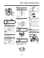
CONTROL FUNCTIONS
STARTING AND BREAK-IN
ENGINE STOP SWITCH
The engine stop switch "1" is located
on the left handlebar. Continue pushing the engine stop switch till the engine comes to a stop.
FUEL
Always use the recommended fuel as
stated below. Also, be sure to use
new gasoline the day of a race.
THROTTLE GRIP
The throttle grip "1" is located on the
right handlebar; it accelerates or decelerates the engine. For acceleration, turn the grip toward you; for
deceleration, turn it away from you.
CLUTCH LEVER
The clutch lever "1" is located on the
left handlebar; it disengages or engages the clutch. Pull the clutch lever
to the handlebar to disengage the
clutch, and release the lever to engage the clutch. The lever should be
pulled rapidly and released slowly for
smooth starts.
SHIFT PEDAL
The gear ratios of the constant-mesh
5 speed transmission are ideally
spaced. The gears can be shifted by
using the shift pedal "1" on the left
side of the engine.
KICKSTARTER CRANK
Rotate the kickstarter crank "1" away
from the engine. Push the starter
down lightly with your foot until the
gears engage, then kick smoothly
and forcefully to start the engine. This
model has a primary kickstarter crank
so the engine can be started in any
gear if the clutch is disengaged. In
normal practices, however, shift to
neutral before starting.
FRONT BRAKE LEVER
The front brake lever "1" is located on
the right handlebar. Pull it toward the
handlebar to activate the front brake.
Recommended fuel:
Premium unleaded
gasoline only
Use only unleaded gasoline. The
use of leaded gasoline will cause
severe damage to the engine internal parts such as valves, piston
rings, and exhaust system, etc.
Your Yamaha engine has been designed to use premium unleaded gasoline with a pump octane number
[(R+M)/2] of 91 or higher, or a research octane number of 95 or higher. If knocking (or pinging) occurs,
use a gasoline of a different brand.
• For refueling, be sure to stop the
engine and use enough care not
to spill any fuel. Also be sure to
avoid refueling close to a fire.
• Refuel after the engine, exhaust
pipe, etc. have cooled off.
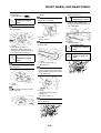
REAR BRAKE PEDAL
The rear brake pedal "1" is located on
the right side of the machine. Press
down on the brake pedal to activate
the rear brake.
STARTER KNOB/IDLE SCREW
The starter knob/idle screw "1" is
used when starting a cold engine.
Pull the starter knob/idle screw out to
open the circuit for starting. When the
engine has warmed up, push it in to
close the circuit.
1-17
Gasohol (For USA and Canada)
There are two types of gasohol: gasohol containing ethanol and that containing methanol. Gasohol containing
ethanol can be used if the ethanol
content does not exceed 10%. Gasohol containing methanol is not recommended by Yamaha because it can
cause damage to the fuel system or
vehicle performance problems.
HANDLING NOTE
Never start or run the engine in a
closed area. The exhaust fumes
are poisonous; they can cause
loss of consciousness and death
in a very short time. Always operate the machine in a well-ventilated
area.
STARTING AND BREAK-IN
• Unlike a two-stroke engine, this
engine cannot be kick started
when the throttle is open because the kickstarter may kick
back. Also, if the throttle is open
the air/fuel mixture may be too
lean for the engine to start.
• Before starting the machine, perform the checks in the pre-operation check list.
AIR FILTER MAINTENANCE
According to "CLEANING THE AIR
FILTER ELEMENT" section in the
CHAPTER 3, apply the foam-air-filter
oil or its equivalent to the element.
(Excess oil in the element may adversely affect engine starting.)
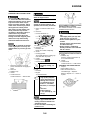
STARTING A COLD ENGINE
1. Inspect the coolant level.
2. Shift the transmission into neutral.
3. Pull the starter knob/ idle screw
"1" to its full length.
Use the starter knob/ idle screw below an air temperature of 15°C
(59°F).
4. Push the kickstarter down lightly
with your foot until resistance is
felt.
5. With the throttle fully closed, fold
out the kickstarter lever, move it
down lightly with your foot until the
gears engage, and then push it
down smoothly but forcefully.
Do not open the throttle while kicking the kickstarter crank. Otherwise, the kickstarter crank may
kick back.
If the engine fails to start, give the
kickstarter 10 to 20 slow kicks at full
throttle in order to clear the engine of
the rich air-fuel mixture retained in it.
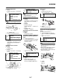
6. When the engine starts running,
warm it up one or two minutes at
a steady speed (of 3,000 to 5,000
r/min), and then return the starter
knob/ idle screw to its original position.
7. Push the engine stop switch "1".
Do not warm up the engine for extended periods of time.
STARTING A WARM ENGINE
To start a warm engine, make sure
that the starter (choke) knob/idling
screw is pushed in and the throttle is
closed, and then start the engine by
pushing the kickstarter.
If the engine fails to start, give the
kickstarter 10 to 20 slow kicks at full
throttle in order to clear the engine of
the rich air-fuel mixture retained in it.
BREAK-IN PROCEDURES
1. Before starting the engine, fill the
fuel tank with the fuel.
2. Perform the pre-operation checks
on the machine.
3. Start and warm up the engine.
Check the idle speed, and check
the operation of the controls and
the engine stop switch. Then, restart the engine and check its operation within no more than 5
minutes after it is restarted.
4. Operate the machine in the lower
gears at moderate throttle openings for five to eight minutes.
5. Check how the engine runs when
the machine is ridden with the
throttle 1/4 to 1/2 open (low to medium speed) for about one hour.
1-18
6. Restart the engine and check the
operation of the machine throughout its entire operating range. Restart the machine and operate it
for about 10 to 15 more minutes.
The machine will now be ready to
race.
• After the break-in or before each
race, you must check the entire
machine for loose fittings and
fasteners as per "TORQUECHECK POINTS". Tighten all
such fasteners as required.
• When any of the following parts
have been replaced, they must
be broken in.
CYLINDER AND CRANKSHAFT:
About one hour of break-in operation is necessary.
PISTON, RING, VALVES, CAMSHAFTS AND GEARS:
These parts require about 30
minutes of break-in operation at
half-throttle or less. Observe the
condition of the engine carefully
during operation.
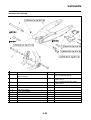
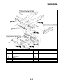
TORQUE-CHECK POINTS
TORQUE-CHECK POINTS
Frame construction
Frame to rear frame
Combined seat and fuel tank
Fuel tank to frame
Exhaust system
Silencer to rear frame
Engine mounting
Frame to engine
Engine bracket to engine
Engine bracket to frame
Steering
Steering stem to handlebar
Steering stem to frame
Steering stem to upper bracket
Upper bracket to handlebar
Suspension
Front
Steering stem to front fork
Rear
For link type
Front fork to upper bracket
Front fork to lower bracket
Assembly of links
Link to frame
Link to rear shock absorber
Link to swingarm
Wheel
Installation of rear shock absorber
Rear shock absorber to frame
Installation of swingarm
Tightening of pivot shaft
Installation of wheel
Front
Tightening of wheel axle
Rear
Tightening of wheel axle
Tightening of axle holder
Wheel to rear wheel sprocket
Brake
Front
Brake caliper to front fork
Brake disc to wheel
Tightening of union bolt
Brake master cylinder to handlebar
Tightening of bleed screw
Tightening of brake hose holder
Rear
Brake pedal to frame
Brake disc to wheel
Tightening of union bolt
Brake master cylinder to frame
Tightening of bleed screw
Tightening of brake hose holder
Fuel system
Fuel pump to fuel tank
Concerning the tightening torque, refer to "TIGHTENING TORQUES" section in the CHAPTER 2.
1-19
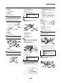
CLEANING AND STORAGE
CLEANING AND STORAGE
CLEANING
Frequent cleaning of your machine
will enhance its appearance, maintain
good overall performance, and extend the life of many components.
1. Before washing the machine,
block off the end of the exhaust
pipe to prevent water from entering. A plastic bag secured with a
rubber band may be used for this
purpose.
2. If the engine is excessively
greasy, apply some degreaser to
it with a paint brush. Do not apply
degreaser to the chain, sprockets,
or wheel axles.
3. Rinse the dirt and degreaser off
with a garden hose; use only
enough pressure to do the job.
Do not use high-pressure washers
or steam-jet cleaners since they
cause water seepage and deterioration seals.
4. After the majority of the dirt has
been hosed off, wash all surfaces
with warm water and a mild detergent. Use an old toothbrush to
clean hard-to-reach places.
5. Rinse the machine off immediately with clean water, and dry all
surfaces with a soft towel or cloth.
6. Immediately after washing, remove excess water from the
chain with a paper towel and lubricate the chain to prevent rust.
7. Clean the seat with a vinyl upholstery cleaner to keep the cover
pliable and glossy.
8. Automotive wax may be applied
to all painted or chromed surfaces. Avoid combination cleanerwaxes, as they may contain abrasives.
9. After completing the above, start
the engine and allow it to idle for
several minutes.
STORAGE
If your machine is to be stored for 60
days or more, some preventive measures must be taken to avoid deterioration. After cleaning the machine
thoroughly, prepare it for storage as
follows:
1. Fill up the fuel tank and add fuel
stabilizer (if available) to prevent
the fuel tank from rusting and the
fuel from deteriorating.
2. Remove the spark plug, pour a tablespoon of SAE 10W-40 motor
oil in the spark plug hole, and reinstall the plug. With the engine
stop switch pushed in, kick the engine over several times to coat the
cylinder walls with oil.
3. Remove the drive chain, clean it
thoroughly with solvent, and lubricate it. Reinstall the chain or store
it in a plastic bag tied to the frame.
4. Lubricate all control cables.
5. Block the frame up to raise the
wheels off the ground.
6. Tie a plastic bag over the exhaust
pipe outlet to prevent moisture
from entering.
7. If the machine is to be stored in a
humid or salt-air environment,
coat all exposed metal surfaces
with a film of light oil. Do not apply
oil to rubber parts or the seat cover.
Make any necessary repairs before
the machine is stored.
1-20
GENERAL SPECIFICATIONS
SPECIFICATIONS
GENERAL SPECIFICATIONS
Model name:
YZ450FZ (USA, CDN, AUS, NZ)
YZ450F (EUROPE, ZA)
Model code number:
33D1 (USA,CDN)
33D2 (EUROPE)
33D4 (AUS, NZ, ZA)
Dimensions:
USA, CDN
EUROPE
Overall length
2,193 mm (86.34
in)
Overall width
825 mm (32.48 in) ←
←
Overall height
1,311 mm (51.61
in)
←
Seat height
999 mm (39.33 in) ←
998 mm (39.29 in)
Wheelbase
1,492 mm (58.74
in)
←
Minimum ground clearance
383 mm (15.08 in) ←
Weight:
With oil and fuel
USA, CDN
111.3 kg (245 lb)
2,191 mm (86.26
in)
AUS, NZ, ZA
←
1,487 mm (58.54
in)
2,194 mm (86.38
in)
384 mm (15.12 in)
EUROPE
111.9 kg (247 lb)
AUS, NZ, ZA
111.5 kg (246 lb)
Engine:
Engine type
Liquid cooled 4-stroke, DOHC
Cylinder arrangement
Single cylinder, Backward inclined
Displacement
449.7 cm3 (15.8 Imp oz, 15.2 US oz)
Bore × stroke
97.0 × 60.8 mm (3.82 × 2.39 in)
Compression ratio
12.5 : 1
Starting system
Kickstarter
Lubrication system:
Dry sump
Oil type or grade:
Engine oil
Recommended brand: YAMALUBE
SAE10W-30, SAE10W-40, SAE10W-50,
SAE15W-40, SAE20W-40 or SAE20W-50
API service SG type or higher,
JASO standard MA
Oil capacity:
Engine oil
Periodic oil change
0.95 L (0.84 Imp qt, 1.00 US qt)
With oil filter replacement
1.0 L (0.88 Imp qt, 1.06 US qt)
Total amount
1.2 L (1.06 Imp qt, 1.27 US qt)
Coolant capacity (including all routes):
1.13 L (0.99 Imp qt, 1.19 US qt)
Air filter:
Wet type element
2-1
2
GENERAL SPECIFICATIONS
Fuel:
Type
Premium unleaded gasoline only
Tank capacity
6.0 L (1.30 Imp gal, 1.59 US gal)
Throttle body:
Type
30RA
Manufacturer
KEIHIN
Spark plug:
Type/manufacturer
CR8E/NGK (resistance type)
Gap
0.7–0.8 mm (0.028–0.031 in)
Clutch type:
Wet, multiple-disc
Transmission:
Primary reduction system
Gear
Primary reduction ratio
61/23 (2.652)
Secondary reduction system
Chain drive
Secondary reduction ratio
48/13 (3.692) (For USA, CDN)
49/13 (3.769) (For EUROPE, AUS, NZ, ZA)
Transmission type
Constant mesh, 5-speed
Operation
Left foot operation
Gear ratio:
1st
27/14 (1.929)
2nd
23/15 (1.533)
3rd
23/18 (1.278)
4th
24/22 (1.091)
5th
20/21 (0.952)
Chassis:
USA, CDN
EUROPE
AUS, NZ, ZA
Frame type
Bilateral beam
←
←
Caster angle
26.9°
26.8°
26.9°
Trail
118.6 mm (4.67
in)
117.5 mm (4.63
in)
119.0 mm (4.69
in)
Tire:
Type
With tube
Size (front)
80/100-21 51M
Size (rear)
120/80-19 63M (For USA, CDN, AUS, NZ, ZA)
110/90-19 62M (For EUROPE)
Tire pressure (front and rear)
100 kPa (1.0 kgf/cm2, 15 psi)
Brake:
Front brake type
Single disc brake
Operation
Right hand operation
Rear brake type
Single disc brake
Operation
Right foot operation
Suspension:
Front suspension
Telescopic fork
Rear suspension
Swingarm (link type monocross suspension)
Shock absorber:
Front shock absorber
Coil spring/oil damper
Rear shock absorber
Coil spring/gas, oil damper
2-2
MAINTENANCE SPECIFICATIONS
Wheel travel:
Front wheel travel
310 mm (12.2 in)
Rear wheel travel
315 mm (12.4 in) (For USA, CDN)
312 mm (12.3 in) (For EUROPE, AUS, NZ, ZA)
Electrical:
Ignition system
TCI
MAINTENANCE SPECIFICATIONS
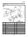
ENGINE
Item
Standard
Limit
Cylinder head:
Warp limit
----
0.05 mm (0.002
in)
Bore size
97.00–97.01 mm (3.8189–3.8193 in)
----
Out of round limit
----
0.05 mm (0.002
in)
Drive method
Chain drive (Left)
----
Camshaft cap inside diameter
22.000–22.021 mm (0.8661–0.8670 in)
----
Cylinder:
Camshaft:
Camshaft outside diameter
21.959–21.972 mm (0.8645–0.8650 in)
----
Shaft-to-cap clearance
0.028–0.062 mm (0.0011–0.0024 in)
0.08 mm (0.003
in)
Intake "A"
37.750–37.850 mm (1.4862–1.4902 in)
37.650 mm
(1.4823 in)
Intake "B"
28.129–28.229 mm (1.1074–1.1114 in)
28.029 mm
(1.1035 in)
Exhaust "A"
33.540–33.640 mm (1.3205–1.3244 in)
33.440 mm
(1.3165 in)
Exhaust "B"
24.769–24.869 mm (0.9752–0.9791 in)
24.669 mm
(0.9712 in)
Camshaft runout limit
----
0.03 mm
(0.0012 in)
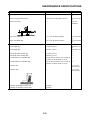
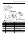
Cam dimensions
2-3
MAINTENANCE SPECIFICATIONS
Item
Standard
Limit
Timing chain:
Timing chain type/No. of links
98XRH2010-122M/122
----
Timing chain adjustment method
Automatic
----
IN
0.10–0.15 mm (0.0039–0.0059 in)
----
EX
0.20–0.25 mm (0.0079–0.0098 in)
----
"A" head diameter (IN)
35.9–36.1 mm (1.4134–1.4213 in)
----
"A" head diameter (EX)
29.9–30.1 mm (1.1772–1.1850 in)
----
Valve, valve seat, valve guide:
Valve clearance (cold)
Valve dimensions:
"B" face width (IN)
2.26 mm (0.089 in)
----
"B" face width (EX)
2.26 mm (0.089 in)
----
"C" seat width (IN)
0.9–1.1 mm (0.0354–0.0433 in)
1.6 mm (0.0630
in)
"C" seat width (EX)
0.9–1.1 mm (0.0354–0.0433 in)
1.6 mm (0.0630
in)
"D" margin thickness (IN)
1.3 mm (0.0512 in)
----
"D" margin thickness (EX)
1.0 mm (0.0394 in)
----
Stem outside diameter (IN)
5.475–5.490 mm (0.2156–0.2161 in)
5.445 mm
(0.2144 in)
Stem outside diameter (EX)
5.465–5.480 mm (0.2152–0.2157 in)
5.435 mm
(0.2140 in)
Guide inside diameter (IN)
5.500–5.512 mm (0.2165–0.2170 in)
5.550 mm
(0.2185 in)
Guide inside diameter (EX)
5.500–5.512 mm (0.2165–0.2170 in)
5.550 mm
(0.2185 in)
2-4
MAINTENANCE SPECIFICATIONS
Item
Standard
Limit
Stem-to-guide clearance (IN)
0.010–0.037 mm (0.0004–0.0015 in)
0.08 mm (0.003
in)
Stem-to-guide clearance (EX)
0.020–0.047 mm (0.0008–0.0019 in)
0.10 mm (0.004
in)
Stem runout limit
----
0.01 mm
(0.0004 in)
Valve seat width (IN)
0.9–1.1 mm (0.0354–0.0433 in)
1.6 mm (0.0630
in)
Valve seat width (EX)
0.9–1.1 mm (0.0354–0.0433 in)
1.6 mm (0.0630
in)
Free length (IN)
40.76 mm (1.60 in)
39.76 mm (1.57
in)
Free length (EX)
37.01mm (1.46 in)
36.01 mm (1.42
in)
Set length (valve closed) (IN)
34.78 mm (1.37 in)
----
Set length (valve closed) (EX)
30.83 mm (1.21 in)
----
Compressed force (installed) (IN)
178–204 N at 34.78 mm (18.2–20.8 kg at
34.78 mm, 40.01–45.86 lb at 1.37 in)
----
Compressed force (installed) (EX)
124–142 N at 30.83 mm (12.6–14.5 kg at
30.83 mm, 27.88–31.92 lb at 1.21 in)
----
Tilt limit* (IN)
----
2.5°/1.8 mm
(2.5°/0.071 in)
Tilt limit* (EX)
----
2.5°/1.6 mm
(2.5°/0.063 in)
Direction of winding (top view) (IN)
Clockwise
----
Direction of winding (top view) (EX)
Clockwise
----
Valve spring:
2-5
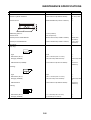
MAINTENANCE SPECIFICATIONS
Item
Standard
Limit
Piston:
Piston to cylinder clearance
0.020–0.045 mm (0.0008–0.0018 in)
0.1 mm (0.004
in)
Piston size "D"
96.965–96.980 mm (3.8175–3.8181 in)
----
Measuring point "H"
9.0 mm (0.354 in)
----
Piston off-set
Zero mm (Zero in)
----
Piston pin bore inside diameter
18.004–18.015 mm (0.7088–0.7093 in)
18.045 mm
(0.7104 in)
Piston pin outside diameter
17.991–18.000 mm (0.7083–0.7087 in)
17.971 mm
(0.7075 in)
Type
Barrel
----
Dimensions (B × T)
1.00 × 3.30 mm (0.04 × 0.13 in)
----
End gap (installed)
0.20–0.30 mm (0.008–0.012 in)
0.55 mm (0.022
in)
Side clearance (installed)
0.015–0.065 mm (0.0015–0.0026 in)
0.120 mm
(0.0047 in)
Type
Taper
----
Dimensions (B × T)
1.00 × 3.10 mm (0.04 × 0.12 in)
----
End gap (installed)
0.35–0.50 mm (0.014–0.020 in)
0.85 mm (0.033
in)
Side clearance
0.020–0.060 mm (0.0008–0.0024 in)
0.120 mm
(0.0047 in)
Piston rings:
Top ring:
2nd ring:
Oil ring:
Dimensions (B × T)
1.5 × 2.55 mm (0.06 × 0.10 in)
----
End gap (installed)
0.2–0.5 mm (0.01–0.02 in)
----
2-6
MAINTENANCE SPECIFICATIONS
Item
Standard
Limit
Crankshaft:
Crank width "A"
61.95–62.00 mm (2.439–2.441 in)
----
Runout limit "C"
0.03 mm (0.0012 in)
0.05 mm (0.002
in)
Big end side clearance "D"
0.15–0.45 mm (0.0059–0.0177 in)
0.50 mm (0.02
in)
Small end free play "F"
0.4–1.0 mm (0.02–0.04 in)
2.0 mm (0.08
in)
Gear
----
Foam-air-filter oil or equivalent oil
----
2.92–3.08 mm (0.115–0.121 in)
2.8 mm (0.110
in)
8
----
Balancer:
Balancer drive method
Air filter oil grade:
Clutch:
Friction plate thickness
Quantity
Clutch plate thickness
1.5–1.7 mm (0.059–0.067 in)
----
Quantity
7
----
Warp limit
----
0.1 mm (0.004
in)
50.0 mm (1.97 in)
49.0 mm (1.93
in)
6
----
0.10–0.35 mm (0.0039–0.0138 in)
----
Clutch spring free length
Quantity
Clutch housing thrust clearance
Clutch housing radial clearance
0.010–0.044 mm (0.0004–0.0017 in)
----
Clutch release method
Inner push, cam push
----
Shifter type
Cam drum and guide bar
----
Guide bar bending limit
----
0.05 mm (0.002
in)
Kick and ratchet type
----
324 kPa (3.24 kg/cm2, 46.1 psi)
----
Shifter:
Kickstarter:
Type
Fuel pump:
Fuel pressure
Fuel injector:
Model/manufacturer
---1010/DENSO
Throttle body:
-------
I. D. mark
33D1 00
----
Manufacturer
KEIHIN
----
2-7
MAINTENANCE SPECIFICATIONS
Item
Standard
Limit
Throttle position sensor:
----
Throttle position sensor maximum resistance
5 kΩ
----
Throttle position sensor variable resistance
0–2 kΩ (full closed)
----
Throttle position sensor input voltage
4–6 V
----
Fuel injection sensor:
Crankshaft position sensor resistance
---248–372 Ω
----
Intake air pressure sensor output voltage
2,
3.57–3.71 V at 101.3kPa (1.013 kg/cm
14.41 psi)
----
Atmospheric pressure sensor output voltage
3.57–3.71 V at 101.3kPa (1.013 kg/cm2,
14.41 psi)
----
Intake air temperature sensor
5.4–6.6 kΩat 0 °C (32 °F)
290–390 Ωat 80 °C (176 °F)
----
Idling condition:
----
Engine idle speed
1,900–2,100 r/min
----
Oil temperature
55–65 °C (131–149 °F)
----
Throttle cable free play
3–5 mm (0.12–0.20 in)
----
Oil filter type
Paper type
----
Oil pump type
Trochoid type
----
Tip clearance
0.12 mm or less (0.0047 in or less)
0.20 mm (0.008
in)
Side clearance
0.09–0.17 mm (0.0035–0.0067 in)
0.24 mm (0.009
in)
Housing and rotor clearance
0.03–0.10 mm (0.0012–0.0039 in)
0.17 mm (0.007
in)
Bypass valve setting pressure
40–80 kPa (0.4–0.8 kg/cm2, 5.69–11.38
psi)
----
Width
121.4 mm (4.78 in)
----
Height
235 mm (9.25 in)
----
28 mm (1.10 in)
----
Lubrication system:
Cooling:
Radiator core size
Thickness
Radiator cap opening pressure
108–137 kPa (1.08 kg/cm2, 15.4 psi–1.37 ---kg/cm2, 19.5 psi)
Radiator capacity (total)
0.62 L (0.55 Imp qt, 0.66 US qt)
----
Single-suction centrifugal pump
----
Water pump
Type
2-8
MAINTENANCE SPECIFICATIONS
CHASSIS
Item
Standard
Limit
Steering system:
Steering bearing type
Taper roller bearing
Front suspension:
----
USA, CDN
EUROPE, AUS, NZ, ZA
Front fork travel
310 mm (12.2 in)
←
----
Fork spring free length
470 mm (18.5 in)
←
465 mm (18.3
in)
Spring rate, STD
K = 4.6 N/mm (0.469 kg/ ←
mm, 26.3 lb/in)
----
Optional spring
Yes
←
----
3
Oil capacity
544 cm (19.1 lmp oz,
18.4 US oz)
←
----
Oil grade
Suspension oil "S1"
←
----
Inner tube outer diameter
48 mm (1.89 in)
←
----
Front fork top end
Zero mm (Zero in)
←
----
Rear suspension:
USA, CDN
EUROPE, AUS, NZ, ZA
Shock absorber travel
132.0 mm (5.20 in)
←
----
Spring free length
260 mm (10.24 in)
←
254.8 mm
(10.03 in)
Fitting length
252 mm (9.92 in)
253 mm (9.96 in)
----
<Min.–Max.>
1.5–18 mm (0.06–0.71
in)
←
Spring rate, STD
K = 56.0 N/mm (5.7 kg/
mm, 319.2 lb/in)
←
----
Optional spring
Yes
←
----
←
----
Preload length
Enclosed gas pressure
1,000 kPa (10 kg/cm
142 psi)
2,
Swingarm:
Swingarm free play limit
End
----
1.0 mm (0.04
in)
Front wheel type
Spoke wheel
----
Rear wheel type
Spoke wheel
----
Front rim size/material
21 × 1.60/Aluminum
----
Rear rim size/material
19 × 2.15/Aluminum
----
Radial
----
2.0 mm (0.08
in)
Lateral
----
2.0 mm (0.08
in)
Type/manufacturer
DID520DMA2 SDH/DAIDO
----
Number of links
113 links + joint
----
Chain slack
50–60 mm (2.0–2.4 in)
----
Chain length (15 links)
----
242.9 mm
(9.563 in)
Wheel:
Rim runout limit:
Drive chain:
2-9
MAINTENANCE SPECIFICATIONS
Item
Standard
Limit
Front disc brake:
Disc outside dia.×Thickness
250 × 3.0 mm (9.84 × 0.12 in)
250 × 2.5 mm
(9.84 × 0.10 in)
Pad thickness
4.4 mm (0.17 in)
1.0 mm (0.04
in)
Master cylinder inside dia.
9.52 mm (0.375 in)
----
Caliper cylinder inside dia.
22.65 mm (0.892 in) × 2
----
Brake fluid type
DOT #4
----
Disc outside dia.×Thickness
245 × 4.0 mm (9.65 × 0.16 in)
245 × 3.5 mm
(9.65 × 0.14 in)
Deflection limit
----
0.15 mm
(0.006 in)
Pad thickness
6.4 mm (0.25 in)
1.0 mm (0.04
in)
Master cylinder inside dia.
11.0 mm (0.433 in)
----
Caliper cylinder inside dia.
25.4 mm (1.000 in) × 1
----
Brake fluid type
DOT #4
----
95 mm (3.74 in)
----
Rear disc brake:
Brake lever and brake pedal:
Brake lever position
Brake pedal height (vertical height above footrest Zero mm (Zero in)
top)
----
Clutch lever free play (lever end)
7–12 mm (0.28–0.47 in)
----
Throttle grip free play
3–5 mm (0.12–0.20 in)
----
ELECTRICAL
Item
Standard
Limit
Ignition system:
Advancer type
Electrical
----
Magneto-model (stator)/manufacturer
33D00/YAMAHA
----
Stator coil resistance (color)
0.60–0.90 Ωat 20 °C (68 °F)
(White–White)
----
Crankshaft position sensor resistance (color)
248–372 Ωat 20 °C (68 °F) (Gray–Black) ----
ECU-model/manufacturer
33D0 (USA, CDN)
----
33D1 (EUROPE)
----
33D3 (AUS, NZ, ZA)
----
Model/manufacturer
F6T541/MITSUBISHI
----
Minimum spark gap
6 mm (0.24 in)
----
Primary coil resistance
3.57–4.83 Ωat 20 °C (68 °F)
----
Secondary coil resistance
10.71–14.49 kΩat 20 °C (68 °F)
----
2.51–2.78 kΩat 20 °C (68 °F)
----
210–220 kΩat 100 °C (212 °F)
----
AC magneto:
Ignition coil:
Coolant temperature sensor:
Coolant temperature sensor resistance
2-10
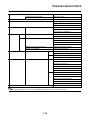
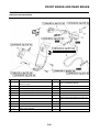
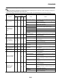
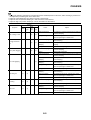
TIGHTENING TORQUES
TIGHTENING TORQUES
ENGINE
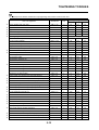
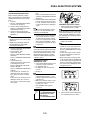
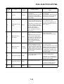
△ - marked portion shall be checked for torque tightening after break-in or before each race.
Part to be tightened
Thread size
Q'ty
M10S × 1.0
Camshaft cap
m•kg
ft•lb
1
13
1.3
9.4
M6 × 1.0
8
10
1.0
7.2
Cylinder head blind plug screw
M12 × 1.0
2
28
2.8
20
Oil passage plug
M8 × 1.25
1
15
1.5
11
Cylinder head (stud bolt)
M6 × 1.0
3
7
0.7
Spark plug
△
△
Tightening torque
Nm
Refer to TIP.
5.1
*1
Cylinder head (bolt)
M10 × 1.25
4
Cylinder head (bolt)
M6 × 1.0
2
10
1.0
7.2
Cylinder head cover
M6 × 1.0
3
10
1.0
7.2
Cylinder
M6 × 1.0
1
10
1.0
7.2
Timing chain tensioner
M6 × 1.0
2
10
1.0
7.2
Timing chain tensioner cap bolt
M6 × 1.0
1
7
0.7
5.1
Timing chain guide stopper plate (exhaust side)
M6 × 1.0
2
10
1.0
7.2
Exhaust pipe (nut)
M6 × 1.0
3
10
1.0
7.2
Exhaust pipe and frame
M8 × 1.25
1
20
2.0
14
Silencer
M8 × 1.25
2
30
3.0
22
Silencer clamp (front)
M8 × 1.25
1
12
1.2
8.7
Silencer clamp (rear)
M8 × 1.25
1
16
1.6
11
Starter knob/Idle screw
M12 × 1.0
1
2
0.2
1.4
Throttle body joint
M6 × 1.0
2
10
1.0
7.2
Throttle body joint clamp
M5 × 0.8
1
3
0.3
2.2
Air filter case
M6 × 1.0
3
7
0.7
5.1
Air filter case cover
M5 × 0.8
2
5
0.5
3.6
Air filter joint clamp
M4 × 0.7
1
4
0.4
2.2
Throttle cable adjust bolt and locknut
M6 × 0.75
1
4
0.4
2.9
Throttle cable (pull)
M10 × 1.25
1
7
0.7
5.1
Throttle cable (return)
M10 × 1.25
1
7
0.7
5.1
Throttle cable cover
M5 × 0.8
2
4
0.4
2.9
Air duct
M6 × 1.0
3
7
0.7
5.1
Radiator
M6 × 1.0
4
10
1.0
7.2
Radiator hose clamp
M6 × 1.0
8
2
0.2
1.4
Radiator pipe 1
M6 × 1.0
1
10
1.0
7.2
Radiator pipe 2
M6 × 1.0
1
10
1.0
7.2
Impeller
M8 × 1.25
1
14
1.4
10
Water pump housing cover
M6 × 1.0
4
10
1.0
7.2
Coolant drain bolt
M6 × 1.0
1
10
1.0
7.2
Oil pump cover
M4 × 0.7
1
2
0.2
1.4
Oil pump
M6 × 1.0
2
10
1.0
7.2
Oil pump drive gear shaft
M6 × 1.0
1
10
1.0
7.2
Oil filter element cover
M6 × 1.0
2
10
1.0
7.2
Oil pressure check bolt
M6 × 1.0
2
10
1.0
7.2
2-11
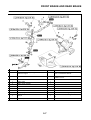
TIGHTENING TORQUES
Part to be tightened
Thread size
Q'ty
Crankshaft end accessing screw
M36 × 1.5
Timing mark accessing screw
Tightening torque
Nm
m•kg
ft•lb
1
10
1.0
7.2
M14 × 1.5
1
6
0.6
4.3
Clutch cover
M6 × 1.0
7
10
1.0
7.2
Right crankcase cover
M6 × 1.0
9
10
1.0
7.2
Left crankcase cover
M6 × 1.0
8
10
1.0
7.2
Crankcase
M6 × 1.0
13
12
1.2
8.7
Clutch cable holder
M6 × 1.0
2
10
1.0
7.2
Oil drain bolt
M8 × 1.25
1
20
2.0
14
Oil drain bolt
M8 × 1.25
1
20
2.0
14
Oil check bolt (crankcase)
M6 × 1.0
1
10
1.0
7.2
Oil strainer
M6 × 1.0
1
10
1.0
7.2
Oil nozzle
M5 × 0.8
1
8
0.8
5.8
Crankcase bearing stopper
M6 × 1.0
8
10
1.0
7.2
Crankcase bearing stopper (crankshaft)
M8 × 1.25
4
22
2.2
16
Drive axle oil seal stopper
M6 × 1.0
2
10
1.0
7.2
Kick shaft ratchet wheel guide
M6 × 1.0
2
12
1.2
8.7
Kickstarter crank
M8 × 1.25
1
33
3.3
24
Screw (kickstarter crank)
M6 × 1.0
1
7
0.7
5.1
Primary drive gear
M20 × 1.0
1
100
10.0
72
Clutch boss
M20 × 1.0
1
75
7.5
54
Clutch cable locknut
M8 × 1.25
1
7
0.7
5.1
Clutch cable adjust bolt and locknut
M6 × 0.75
1
4
0.4
2.9
Clutch spring
M6 × 1.0
6
10
1.0
7.2
Balancer
M10 × 1.0
1
45
4.5
32
Balancer shaft driven gear
M14 × 1.0
1
50
5.0
36
Balancer weight
M6 × 1.0
3
10
1.0
7.2
Drive sprocket
M20 × 1.0
1
75
7.5
54
Drive chain sprocket cover
M6 × 1.0
2
7
0.7
5.1
Shift pedal
M6 × 1.0
1
12
1.2
8.7
Shift guide
M6 × 1.0
2
10
1.0
7.2
Stopper lever
M6 × 1.0
1
10
1.0
7.2
Segment
M8 × 1.25
1
30
3.0
22
*1: Tighten the cylinder head bolts to 30 Nm (3.0 m•kg, 22 ft•lb) in the proper tightening sequence, remove and retighten
the cylinder head bolts to 20 Nm (2.0 m•kg, 14 ft•lb) in the proper tightening sequence, and then tighten the cylinder head
bolts further to reach the specified angle 150° in the proper tightening sequence.
2-12
TIGHTENING TORQUES
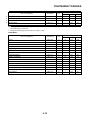
CHASSIS
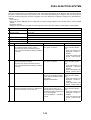
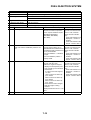
△ - marked portion shall be checked for torque tightening after break-in or before each race.
Part to be tightened
Thread size
Q'ty
Tightening torque
Nm
m•kg
ft•lb
△
Upper bracket and outer tube
M8 × 1.25
4
21
2.1
15
△
Lower bracket and outer tube
M8 × 1.25
4
21
2.1
15
△
Upper bracket and steering stem
M24 × 1.0
1
145
14.5
105
△
Handlebar upper holder
M8 × 1.25
4
28
2.8
20
△
Handlebar lower holder
M10 × 1.25
2
34
3.4
24
△
Steering ring nut
M28 × 1.0
1
Front fork and damper assembly
M51 × 1.5
2
Front fork and adjuster
M22 × 1.25
2
55
5.5
40
Damper assembly and base valve
M42 × 1.5
2
29
2.9
21
Adjuster and damper assembly
M12 × 1.25
2
29
2.9
21
M5 × 0.8
2
1
0.1
0.7
Bleed screw (front fork) and base valve
Refer to TIP.
30
3.0
22
△
Front fork and front fork protector
M6 × 1.0
6
5
0.5
3.6
△
Front fork protector and brake hose holder
M6 × 1.0
2
8
0.8
5.8
Throttle grip cap
M5 × 0.8
2
4
0.4
2.9
Clutch lever holder
M6 × 1.0
2
5
0.5
3.6
Clutch lever mounting nut
M6 × 1.0
1
4
0.4
2.9
Clutch lever position lock nut
M5 × 0.8
1
5
0.5
3.6
Front brake master cylinder and bracket
M6 × 1.0
2
9
0.9
6.5
Front brake master cylinder cap
M4 × 0.7
2
2
0.2
1.4
Brake lever mounting bolt
M6 × 1.0
1
6
0.6
4.3
Brake lever mounting nut
M6 × 1.0
1
6
0.6
4.3
Brake lever position locknut
M6 × 1.0
1
5
0.5
3.6
△
Cable guide (front brake hose) and under bracket
M6 × 1.0
1
4
0.4
2.9
△
Front brake hose union bolt (brake master cylinder)
M10 × 1.25
1
30
3.0
22
△
Front brake hose union bolt (brake caliper)
M10 × 1.25
1
30
3.0
22
△
Front brake caliper and front fork
M8 × 1.25
2
28
2.8
20
Brake caliper (front and rear) and pad pin plug
M10 × 1.0
2
2
0.2
1.4
△
Brake caliper (front and rear) and pad pin
M10 × 1.0
2
18
1.8
13
△
Brake caliper (front and rear) and bleed screw
M8 × 1.25
2
6
0.6
4.3
△
Front wheel axle and axle nut
M16 × 1.5
1
105
10.5
75
△
Front wheel axle holder
M8 × 1.25
4
21
2.1
15
△
Front brake disc and wheel hub
M6 × 1.0
6
12
1.2
8.7
△
Rear brake disc and wheel hub
M6 × 1.0
6
14
1.4
10
△
Footrest bracket and frame
M10 × 1.25
4
55
5.5
40
△
Brake pedal mounting
M8 × 1.25
1
26
2.6
19
Brake pedal position locknut
M6 × 1.0
1
6
0.6
4.3
Rear brake master cylinder and frame
M6 × 1.0
2
10
1.0
7.2
Rear brake master cylinder cap
M4 × 0.7
2
2
0.2
1.4
30
3.0
22
△
△
△
Rear brake hose union bolt (brake caliper)
M10 × 1.25
1
△
Rear brake hose union bolt (brake master cylinder)
M10 × 1.25
1
30
3.0
22
△
Rear wheel axle and axle nut
M22 × 1.5
1
135
13.5
98
2-13
TIGHTENING TORQUES
Part to be tightened
Thread size
Q'ty
M8 × 1.25
—
Tightening torque
Nm
m•kg
ft•lb
6
42
4.2
30
72
3
0.3
2.2
△
Driven sprocket and wheel hub
△
Nipple (spoke)
△
Disc cover and rear brake caliper
M6 × 1.0
2
10
1.0
7.2
△
Protector and rear brake caliper
M6 × 1.0
2
7
0.7
5.1
Drive chain puller adjust bolt and locknut
M8 × 1.25
2
21
2.1
15
Engine mounting:
△
Upper engine bracket and frame
M8 × 1.25
4
45
4.5
32
△
Front engine bracket and frame
M8 × 1.25
4
34
3.4
24
△
Engine and engine bracket (front)
M10 × 1.25
1
53
5.3
38
△
Engine and engine bracket (upper)
M10 × 1.25
2
45
4.5
32
△
Engine and frame (lower)
M10 × 1.25
1
53
5.3
38
△
Engine guard
M6 × 1.0
1
10
1.0
7.2
Lower engine guard
M6 × 1.0
3
10
1.0
7.2
△
Pivot shaft and nut
M16 × 1.5
1
85
8.5
61
△
Relay arm and swingarm
M14 × 1.5
1
70
7.0
50
△
Relay arm and connecting rod
M14 × 1.5
1
80
8.0
58
△
Connecting rod and frame
M14 × 1.5
1
80
8.0
58
△
Rear shock absorber and frame
M10 × 1.25
1
56
5.6
40
△
Rear shock absorber and relay arm
M10 × 1.25
1
53
5.3
38
△
Rear shock absorber locknut
M60 × 1.5
1
30
3.0
22
△
Rear frame and frame (upper)
M8 × 1.25
1
32
3.2
23
△
Rear frame and frame (lower)
M8 × 1.25
2
32
3.2
23
△
Swingarm and brake hose holder
M5 × 0.8
4
3
0.3
2.2
Upper drive chain tensioner
M8 × 1.25
1
16
1.6
11
Lower drive chain tensioner
M8 × 1.25
1
16
1.6
11
Drive chain support and swingarm
M6 × 1.0
3
7
0.7
5.1
△
Seal guard and swingarm
△
Fuel tank mounting boss and frame
△
△
△
△
M5 × 0.8
3
4
0.4
2.9
M10 × 1.25
1
20
2.0
14
Fuel tank (front)
M6 × 1.0
2
9
0.9
6.5
Fuel tank bracket (front)
M6 × 1.0
4
7
0.7
5.1
Fuel tank (rear)
M6 × 1.0
2
9
0.9
6.5
Fuel tank bracket (rear)
M6 × 1.0
2
7
0.7
5.1
Fuel pump
M5 × 0.8
6
4
0.4
2.9
Fuel tank side cover
M6 × 1.0
4
7
0.7
5.1
Fuel tank and seat set bracket
M6 × 1.0
1
7
0.7
5.1
Fuel tank and fuel tank bracket
M6 × 1.0
4
7
0.7
5.1
Seat
M8 × 1.25
2
22
2.2
16
Side cover
M6 × 1.0
4
7
0.7
5.1
Heat protector
M5 × 0.8
2
4
0.4
2.9
△
Air scoop and fuel tank
M6 × 1.0
2
9
0.9
6.5
△
Air scoop and air duct
M6 × 1.0
2
7
0.7
5.1
radiator and radiator guard
M6 × 1.0
2
10
1.0
7.2
△
Air scoop and radiator guard
M6 × 1.0
2
7
0.7
5.1
△
Front fender
M6 × 1.0
4
10
1.0
7.2
2-14
TIGHTENING TORQUES
Part to be tightened
Thread size
Q'ty
Tightening torque
Nm
m•kg
ft•lb
△
Rear fender (front)
M6 × 1.0
3
7
0.7
5.1
△
Rear fender (rear)
M6 × 1.0
2
18
1.8
13
△
Mud flap
—
2
1
0.1
0.7
△
Number plate
M6 × 1.0
1
7
0.7
5.1
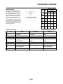
1. First, tighten the steering ring nut approximately 38 Nm (3.8 m•kg, 27 ft•lb) by using the steering nut wrench, then loosen
the steering ring nut one turn.
2. Retighten the steering ring nut 7 Nm (0.7 m•kg, 5.1 ft•lb).
ELECTRICAL
Part to be tightened
Thread size
Q'ty
Stator
M5 × 0.8
Rotor
M12 × 1.25
Tightening torque
Nm
m•kg
ft•lb
3
8
0.8
5.8
1
65
6.5
47
Crankshaft position sensor
M6 × 1.0
2
10
1.0
7.2
Throttle position sensor
M5 × 0.8
1
3
0.3
2.2
Injector
M5 × 0.8
2
3
0.3
2.2
Ignition coil
M5 × 0.8
2
4
0.4
2.9
Coolant temperature sensor
M10 × 1.25
1
16
1.6
11
Rectifier/regulator
M6 × 1.0
2
7
0.7
5.1
Ignition coil bracket
M6 × 1.0
2
10
1.0
7.2
Intake air pressure sensor
M5 × 0.8
1
5
0.5
3.6
Atmospheric pressure sensor
M5 × 0.8
1
4
0.4
2.9
Atmospheric pressure sensor bracket
M6 × 1.0
1
7
0.7
5.1
Condenser bracket
M6 × 1.0
2
7
0.7
5.1
Ground lead
M5 × 0.8
1
4
0.4
2.9
ECU
M5 × 0.8
2
4
0.4
2.9
ECU bracket
M6 × 1.0
2
7
0.7
5.1
2-15
TIGHTENING TORQUES
GENERAL TORQUE
SPECIFICATIONS
This chart specifies torque for standard fasteners with standard I.S.O.
pitch threads. Torque specifications
for special components or assemblies are included in the applicable
sections of this book. To avoid warpage, tighten multi-fastener assemblies in a crisscross fashion, in
progressive stages, until full torque is
reached. Unless otherwise specified,
torque specifications call for clean,
dry threads. Components should be
at room temperature.
B
A
(Bolt
(Nut)
)
A. Distance between flats
B. Outside thread diameter
TORQUE SPECIFICATION
Nm
m•kg
ft•lb
10
mm
6 mm
6
0.6
4.3
12
mm
8 mm
15
1.5
11
14
mm
10
mm
30
3.0
22
17
mm
12
mm
55
5.5
40
19
mm
14
mm
85
8.5
61
22
mm
16
mm
130
13
94
DEFINITION OF UNITS
Unit
Read
Definition
-3
Measure
millimeter
10 meter
Length
cm
centimeter
10-2
Length
kg
kilogram
103 gram
mm
meter
Weight
2
N
Newton
1 kg × m/sec
Nm
Newton meter
N×m
Torque
m•kg
Meter kilogram
m × kg
Torque
2
Force
Pa
Pascal
N/m
Pressure
N/mm
Newton per millimeter
N/mm
L
Liter
cm3
Cubic centimeter
—
Volume or capacity
r/min
Revolution per minute
—
Engine speed
Spring rate
—
2-16
Volume or capacity
LUBRICATION DIAGRAMS
LUBRICATION DIAGRAMS
1.
2.
3.
4.
5.
6.
7.
8.
9.
Oil strainer
Oil check bolt
Scavenging pump
Oil feed pump
Oil filter element
Crankshaft
Oil nozzle
Exhaust camshaft
Intake camshaft
10.
11.
12.
13.
Main axle
Drive axle
Oil level check window
Oil tank
2-17
CABLE ROUTING DIAGRAM
CABLE ROUTING DIAGRAM
2-18
CABLE ROUTING DIAGRAM
1.
2.
3.
4.
5.
Fuel tank breather hose
Coupler for connecting optional
part
Cylinder head breather hose
Hose holder
Radiator hose 3
A.
B.
C.
D.
E.
Insert the end of the fuel tank
breather hose into the hole in
the steering stem.
Fit the accessory coupler into
the connector to fasten it to the
bracket.
Point the end of the cylinder
head breather hose downward.
Pass the cylinder head breather
hose through the hose holder,
making sure that the stopper on
the hose contacts the holder.
Route the cylinder head breather hose between the frame and
radiator hose 3, and to the outside of the AC magneto lead.
2-19
CABLE ROUTING DIAGRAM
F-F
F
A
A
F
B
E
D
D
C
100mm
C
E
D-D
C-C
2-20
B
CABLE ROUTING DIAGRAM
1.
2.
3.
4.
5.
6.
7.
8.
9.
10.
11.
12.
13.
14.
15.
16.
17.
Clutch cable
Throttle cable (return)
Throttle cable (pull)
Cable holder
Clamp
Rectifier/regulator
Ignition coil
Ignition coil coupler
AC magneto coupler
Radiator hose 2
Ground lead terminal
Plug cap
Ignition coil bracket
Clamp (lock)
Clamp (clip)
AC magneto lead
ECU bracket
A.
B.
C.
D.
E.
F.
G.
H.
I.
J.
K.
L.
M.
N.
O.
Pass the clutch cable, throttle
cables, and engine stop switch
lead through the cable holder.
Pass the clutch cable through
the lower guide only.
Route the engine stop switch
lead to the inside of the clip.
Fasten the rectifier/regulator
lead and engine stop switch lead
(wire harness end).
Insert the projection on the engine stop switch coupler into the
hole in the bracket.
Insert the projection on the rectifier/regulator coupler into the
hole in the bracket.
Position the ignition coil bracket
to the outside of the ignition coil,
and insert the bolts from the ignition coil side.
Fasten the AC magneto lead to
the ignition coil bracket with a
plastic locking tie, making sure
to position the tie above the lower mounting portion of the bracket. Face the buckle of the plastic
locking tie forward, and then cut
off the excess end of the tie.
Route the ignition coil lead between the condenser and the ignition coil.
Fit the clip portion of the clamp
into the ignition coil bracket and
fasten the clutch cable with the
locking portion of the clamp.
Route the clutch cable to the
outside of the AC magneto lead.
Route the throttle cables under
radiator hose 2, making sure not
to twist the cables.
Route the AC magneto lead to
the inside of the throttle cables
and clutch cable.
Install the ground lead terminal
between the ECU bracket and
the cable holder, making sure to
position the terminal between
the stoppers.
Push in the spark plug cap completely, making sure that there is
no gap between the cylinder
head cover and the cap.
Apply sealant to the slit and inner surface of the grommet, and
then install the grommet at the
position shown.
2-21
CABLE ROUTING DIAGRAM
G
G
A-A
B-B
A
A
B
B
F
F
C-C
C
C
D
D
E
D-D
E
E-E
2-22
CABLE ROUTING DIAGRAM
1.
2.
3.
4.
5.
6.
7.
8.
9.
10.
11.
12.
13.
14.
15.
16.
17.
18.
19.
20.
21.
22.
23.
Tension pipe
Coolant temperature sensor
coupler
Front engine bracket
Fuel pump coupler
Fuel pump
Intake air temperature sensor
coupler
Radiator hose 2
Radiator breather hose
Radiator hose 1
Radiator hose 4
Radiator pipe 2
Radiator hose 3
Cylinder head breather hose
Frame
ECU (electronic control unit)
ECU bracket
Main harness
AC magneto lead
Throttle position sensor lead
Condenser lead
Coolant temperature sensor
lead
Ignition coil lead
Condenser
A.
B.
C.
D.
E.
F.
G.
H.
I.
J.
K.
Fasten the wire harness at the
positioning tape to the ECU
bracket with a plastic locking tie.
Face the buckle of the plastic
locking tie downward, and then
cut off the excess end of the tie.
Install the cover onto the wire
harness coupler.
Route the condenser lead, throttle position sensor lead, coolant
temperature sensor lead, ignition coil lead, and AC magneto
lead under radiator hose 2.
Connect the vacuum hose to the
atmospheric pressure sensor,
and then fasten the hose with
the clamp. Make sure to face the
moving part of the sensor rearward.
After connecting the condenser
coupler, install the coupler cover
onto the coupler.
After connecting the throttle position sensor coupler, install the
coupler cover onto the coupler.
Fasten the AC magneto lead,
condenser lead, throttle position
sensor lead, coolant temperature sensor lead, and ignition
coil lead to the frame with the
plastic band, making sure to position the band between the ignition coil bracket and the tension
pipe. Face the buckle of the
plastic band to the right with the
end pointing rearward.
Point the end of the vacuum
hose rearward.
Fit the bracket into the hole in
the rubber portion of the condenser.
Fasten the radiator breather
hose to the frame with the plastic band, making sure to position
the band above the front engine
bracket. Face the buckle of the
plastic band outward with the
end pointing rearward.
After connecting the coolant
temperature sensor coupler, install the coupler cover onto the
coupler.
2-23
L.
M.
N.
O.
P.
Q.
R.
S.
T.
Route the radiator breather hose
between the down tubes.
Fasten the fuel hose and fuel
pump lead with the plastic band,
making sure to position the band
between the bend in the fuel
hose protector and the end of
the protector. Point the end of
the plastic band upward.
Insert the projection on the joint
coupler into the hole in the
bracket, and then install the coupler cover onto the coupler.
Route the atmospheric pressure
sensor lead, intake air pressure
sensor lead, intake air temperature sensor lead, fuel injector
lead, and fuel pump lead above
radiator hose 2. Position the
joint coupler above radiator
hose 2.
Route the radiator breather hose
to the inside of radiator hose 1
and the front engine bracket.
Hose installation position
(1.3–3.3 mm, 0.05–0.13 in)
Clip installation position (0–2.0
mm, 0–0.08 in)
Install the washer so that it contacts the bolt head.
Install the collar so that the
flange on the collar contacts the
ECU bracket.
CABLE ROUTING DIAGRAM
1.
2.
3.
4.
5.
6.
7.
Ignition coil coupler
Coolant temperature sensor
lead
Atmospheric pressure sensor
coupler
Intake air temperature sensor
lead
Clamp
Intake air pressure sensor coupler
Cover
8
9.
10.
11.
12.
13.
14.
Fuel hose
Fuel pump lead
Fuel injector coupler
Throttle body
High tension code
Throttle cable
AC magneto lead
A.
B.
C.
2-24
Route the fuel pump lead to the
outside of the fuel hose and
above the cover.
Route the spark plug wire between the throttle cables and the
throttle body. When installing
the air filter, be sure not to pinch
the spark plug wire.
Route the AC magneto lead to
the inside of the throttle cables.
CABLE ROUTING DIAGRAM
1.
2.
3.
Brake master cylinder
Brake hose holder
Brake hose
A.
B.
Install the brake hose so that its
pipe portion directs as shown
and lightly touches the projection on the brake caliper.
Pass the brake hose into the
brake hose holders.
2-25
C.
D.
If the brake hose contacts the
spring (rear shock absorber),
correct its twist.
Install the brake hose so that its
pipe portion directs as shown
and lightly touches the projection on the brake master cylinder.
CABLE ROUTING DIAGRAM
1.
2.
3.
4.
5.
6.
Throttle cable
Clutch cable
Clamp
Engine stop switch lead
Hose guide
Main harness
A.
B.
C.
D.
Route the clutch cable to the
rear of the number plate band.
Fasten the engine stop switch
lead to the handlebar.
Route the brake hose to the
front of the number plate.
Pass the clutch cable through
the cable guide on the number
plate.
2-26
MAINTENANCE INTERVALS
REGULAR INSPECTION AND ADJUSTMENTS
MAINTENANCE INTERVALS
• The following schedule is intended as a general guide to maintenance and lubrication. Bear in mind that such factors as
weather, terrain, geographical location, and individual usage will alter the required maintenance and lubrication intervals.
If you are a doubt as to what intervals to follow in maintaining and lubricating your machine, consult your Yamaha dealer.
• Periodic inspection is essential in making full use of the machine performance. The service life of the parts varies substantially according to the environment in which the machine runs (e.g., rain, dirt, etc.). Therefore, earlier inspection is
required by reference to the list below..
Item
After
breakin
Every
race
(about
2.5
hours)
Every
third
(about
7.5
hours)
Every
fifth
(about
12.5
hours)
As required
Remarks
ENGINE OIL
Replace
●
●
VALVES
Check the valve clearances
●
The engine must be cold.
●
Inspect
Check the valve seats and valve
stems for wear.
●
Replace
●
VALVE SPRINGS
Inspect
Check the free length and the tilt.
●
Replace
●
VALVE LIFTERS
Inspect
Check for scratches and wear.
●
Replace
●
CAMSHAFTS
Inspect the camshaft surface.
Inspect
Inspect the decompression system.
●
Replace
●
CAMSHAFT SPROCKETS
Inspect
Check for wear on the teeth and for
damage.
●
Replace
●
PISTON
Inspect
●
Inspect crack.
Clean
●
Inspect carbon deposits and eliminate
them.
●
Replace the piston, piston pin, piston
pin clip, and piston ring all as a set.
●
Check ring end gap.
●
Replace the piston, piston pin, piston
pin clip, and piston ring all as a set.
Replace
●
PISTON RING
Inspect
Replace
●
PISTON PIN
Inspect
●
Replace
●
3-1
●
Replace the piston, piston pin, piston
pin clip, and piston ring all as a set.
3
MAINTENANCE INTERVALS
Item
After
breakin
Every
race
(about
2.5
hours)
Every
third
(about
7.5
hours)
Every
fifth
(about
12.5
hours)
As required
CYLINDER HEAD
Remarks
Inspect carbon deposits and eliminate
them.
Inspect and clean
●
Change gasket.
●
Inspect score marks.
CYLINDER
Inspect and clean
Replace
●
Inspect wear.
CLUTCH
Inspect and adjust
●
Inspect housing, friction plate, clutch
plate and spring.
●
Replace
●
TRANSMISSION
Inspect
●
Replace bearing
●
SHIFT FORK, SHIFT CAM,
GUIDE BAR
Inspect
●
Inspect wear.
ROTOR NUT
Retighten
●
●
EXHAUST PIPE, SILENCER,
PROTECTOR
Inspect and retighten
●
●
Clean
●
Replace fiver
●*
●
* When the exhaust sound becomes
louder or when a performance drop is
felt.
CRANK
Inspect and clean
●
●
THROTTLE BODY
Inspect
●
SPARK PLUG
Inspect and clean
●
●
Replace
●
DRIVE CHAIN
Lubricate, slack, alignment
Use chain lube.
●
Chain slack: 50–60 mm (2.0–2.4 in)
●
Replace
●
COOLING SYSTEM
Check coolant level and leakage
●
●
Check radiator cap operation
●
Replace coolant
●
Inspect hoses
Every two years
●
OUTSIDE NUTS AND BOLTS
Retighten
●
Refer to "STARTING AND BREAKIN" section in the CHAPTER 1.
●
3-2
MAINTENANCE INTERVALS
Item
After
breakin
Every
race
(about
2.5
hours)
●
●
Every
third
(about
7.5
hours)
Every
fifth
(about
12.5
hours)
As required
Remarks
AIR FILTER
Clean and lubricate
Use foam air-filter oil or equivalent oil.
Replace
●
OIL FILTER
Replace
●
●
ENGINE GUARD
Replace
●
Breakage
FRAME
Clean and inspect
●
●
FUEL TANK, FUEL PUMP
inspect
●
●
FUEL HOSE
Inspect
●
Replace
●
Every four years
BRAKES
Adjust lever position and pedal
height
●
●
Lubricate pivot point
●
●
Check brake disc surface
●
●
Check fluid level and leakage
●
●
Retighten brake disc bolts, caliper bolts, master cylinder bolts
and union bolts
●
●
Replace pads
●
Replace brake fluid
●
Every one year
FRONT FORKS
Inspect and adjust
●
Replace oil
●
●
Suspension oil "S1"
●
Replace oil seal
●
FRONT FORK OIL SEAL AND
DUST SEAL
Clean and lube
●
Lithium base grease
●
PROTECTOR GUIDE
Replace
●
REAR SHOCK ABSORBER
Inspect and adjust
●
●
Lube
Retighten
●
●
●
●
●
DRIVE CHAIN GUIDE AND
ROLLERS
Inspect
3-3
(After
rain
ride) ● Molybdenum disulfide grease
MAINTENANCE INTERVALS
Item
Every
third
(about
7.5
hours)
Every
fifth
(about
12.5
hours)
After
breakin
Every
race
(about
2.5
hours)
●
●
Molybdenum disulfide grease
●
●
Molybdenum disulfide grease
●
●
As required
Remarks
SWINGARM
Inspect, lube and retighten
RELAY ARM, CONNECTING
ROD
Inspect, lube and retighten
STEERING HEAD
Inspect free play and retighten
Clean and lube
Lithium base grease
●
Replace bearing
●
TIRE, WHEELS
Inspect air pressure, wheel runout, tire wear and spoke looseness
●
●
Retighten sprocket bolt
●
●
Inspect bearings
●
Replace bearings
●
Lubricate
●
Lithium base grease
THROTTLE, CONTROL CABLE
Check routing and connection
●
●
Lubricate
●
●
Yamaha cable lube or SAE 10W-40
motor oil
3-4
PRE-OPERATION INSPECTION AND MAINTENANCE
PRE-OPERATION INSPECTION AND MAINTENANCE
Before riding for break-in operation, practice or a race, make sure the machine is in good operating condition.
Before using this machine, check the following points.
GENERAL INSPECTION AND MAINTENANCE
Item
Routine
Page
Coolant
Check that coolant is filled up to the radiator cap. Check the cooling system for leakage.
P.3-6 – 7
Fuel
Check that a fresh gasoline is filled in the fuel tank. Check the fuel
line for leakage.
P.1-17
Engine oil
Check that the oil level is correct. Check the crankcase and oil line
for leakage.
P.3-9 – 10
Gear shifter and clutch
Check that gears can be shifted correctly in order and that the
clutch operates smoothly.
P.3-7
Throttle grip/Housing
Check that the throttle grip operation and free play are correctly
adjusted. Lubricate the throttle grip and housing, if necessary.
P.3-8
Brakes
Check the play of front brake and effect of front and rear brake.
P.3-14 – 17
Drive chain
Check drive chain slack and alignment. Check that the drive chain
is lubricated properly.
P.3-17 –18
Wheels
Check for excessive wear and tire pressure. Check for loose
spokes and have no excessive play.
Steering
Check that the handlebar can be turned smoothly and have no excessive play.
Front forks and rear shock
absorber
Check that they operate smoothly and there is no oil leakage.
P.3-21
P.3-21 – 22
P.3-18 – 20
Cables (wires)
Check that the clutch and throttle cables move smoothly. Check
that they are not caught when the handlebars are turned or when
the front forks travel up and down.
—
Exhaust pipe
Check that the exhaust pipe is tightly mounted and has no cracks.
P.4-3 – 6
Rear wheel sprocket
Check that the rear wheel sprocket tightening bolt is not loose.
P.3-17
Lubrication
Check for smooth operation. Lubricate if necessary.
P.3-23
Bolts and nuts
Check the chassis and engine for loose bolts and nuts.
P.1-19
Lead connectors
Check that the AC magneto, ECU and ignition coil are connected
tightly.
P.1-10 – 11
Settings
Is the machine set suitably for the condition of the racing course
and weather or by taking into account the results of test runs before racing? Are inspection and maintenance completely done?
P.8-1 – 5
3-5
ENGINE
ENGINE
CHANGING THE COOLANT
CHECKING THE COOLANT LEVEL
Do not remove the radiator cap
"1", drain bolt and hoses when the
engine and radiator are hot. Scalding hot fluid and steam may be
blown out under pressure, which
could cause serious injury. When
the engine has cooled, place a
thick towel over the radiator cap,
slowly rotate the cap counterclockwise to the detent. This procedure allows any residual
pressure to escape. When the
hissing sound has stopped, press
down on the cap while turning
counterclockwise and remove it.
Hard water or salt water is harmful
to the engine parts. You may use
distilled water, if you can't get soft
water.
1. Place the machine on a level
place, and hold it in an upright position.
2. Remove:
• Radiator cap
3. Check:
• Coolant level "a"
Coolant level low → Add coolant.
1.
Radiator
Do not remove the radiator cap
when the engine is hot.
Take care so that coolant does not
splash on painted surfaces. If it
splashes, wash it away with water.
1. Place a container under the engine.
2. Remove:
• Coolant drain bolt "1"
3. Remove:
• Radiator cap
Drain the coolant completely.
4. Clean:
• Cooling system
Thoroughly flush the cooling system with clean tap water.
5. Install:
• Copper washer
• Coolant drain bolt
Coolant drain bolt:
10 Nm (1.0 m•kg, 7.2
ft•lb)
6. Fill:
• Radiator
• Engine
To specified level.
Recommended coolant:
High quality ethylene
glycol anti-freeze containing anti-corrosion
for aluminum engine
Coolant "1" and water
(soft water) "2" mixing ratio:
50%/50%
Coolant capacity:
1.13 L (0.99 Imp qt, 1.19
US qt)
• Do not mix more than one type of
ethylene glycol antifreeze containing corrosion inhibitors for
aluminum engine.
• Do not use water containing impurities or oil.
3-6
Handling notes of coolant:
The coolant is harmful so it should be
handled with special care.
• When coolant splashes to your
eye.
Thoroughly wash your eye with
water and see your doctor.
• When coolant splashes to your
clothes.
Quickly wash it away with water
and then with soap.
• When coolant is swallowed.
Quickly make him vomit and take
him to a doctor.
7. Install:
• Radiator cap
Start the engine and warm it up
for a several minutes.
8. Check:
• Coolant level
Coolant level low → Add coolant.
CHECKING THE RADIATOR CAP
1. Inspect:
• Seal (radiator cap) "1"
• Valve and valve seat "2"
Crack/damage → Replace.
Exist fur deposits "3" → Clean or
replace.
ENGINE
CHECKING THE RADIATOR CAP
OPENING PRESSURE
1. Attach:
• Radiator cap tester "1" and adapter "2"
Radiator cap tester:
YU-24460-01/9089001325
Radiator cap tester
adapter:
YU-33984/90890-01352
Apply water on the radiator cap seal.
3. Radiator cap
2. Apply the specified pressure.
Radiator cap opening
pressure:
108–137 kPa (1.08–1.37
kg/cm2, 15.4–19.5 psi)
3. Inspect:
• Pressure
Impossible to maintain the specified pressure for 10 seconds →
Replace.
CHECKING THE COOLING
SYSTEM
1. Inspect:
• Coolant level
2. Attach:
• Radiator cap tester "1" and adapter "2"
Radiator cap tester:
YU-24460-01/9089001325
Radiator cap tester
adapter:
YU-33984/90890-01352
3. Apply the specified pressure.
Standard pressure:
196 kPa (1.96 kg/cm2,
27.9 psi)
• Do not apply pressure more than
specified pressure.
• Radiator should be filled fully.
4. Inspect:
• Pressure
Impossible to maintain the specified pressure for 10 seconds →
Repair.
• Radiator
• Radiator hose joint
Coolant leakage → Repair or replace.
• Radiator hose
Swelling → Replace.
ADJUSTING THE CLUTCH LEVER
POSITION
1. Adjust:
• Clutch lever position
Clutch lever position adjustment
steps:
a. Loosen the locknuts "1".
b. Turn the adjusting bolt "2" until the
clutch lever position "a" is in the
desiered position .
c. Tighten the locknuts.
ADJUSTING THE CLUTCH CABLE
FREE PLAY
1. Check:
• Clutch lever free play "a"
Out of specification → Adjust.
Clutch lever free play "a"
:
7–12 mm (0.28–0.47 in)
2. Adjust:
• Clutch lever free play
Clutch lever free play adjustment
steps:
a. Loosen the locknuts "1".
b. Turn the adjuster "2" until free
play "a" is within the specified limits.
c. Tighten the locknuts.
Locknut:
4 Nm (0.4 m•kg, 2.9
ft•lb)
• Before adjustment, expose the adjuster by moving the boot "3" and
cap "4" away.
• Make minute adjustment on the lever side using the adjuster "5".
• After adjustment, check proper operation of clutch lever.
Locknut:
5 Nm (0.5 m•kg, 3.6
ft•lb)
2. Adjust:
• Clutch cable free play
Refer to "ADJUSTING THE
CLUTCH CABLE FREE PLAY".
3-7
3. Install:
• Cap "1"
• Boot "2"
ENGINE
ADJUSTING THE THROTTLE
CABLE FREE PLAY
1. Check:
• Throttle grip free play "a"
Out of specification → Adjust.
2. Apply:
• Lithium soap base grease
On the throttle cable end "a".
4. Loosen and release the binder "1"
and lift the air filter case lid.
Hold the air filter case lid by the use of
the binder.
Throttle grip free play
"a":
3–5 mm (0.12–0.20 in)
3. Install:
• Throttle grip cap
• Screw (throttle grip cap)
2. Adjust:
• Throttle grip free play
Throttle grip free play adjustment
steps:
a. Slide the adjuster cover.
b. Loosen the locknut "1".
c. Turn the adjuster "2" until the
specified free play is obtained.
d. Tighten the locknut.
Before adjusting the throttle cable
free play, the engine idle speed
should be adjusted.
Screw (throttle grip cap):
4 Nm (0.4 m•kg, 2.9
ft•lb)
• Cover (grip cap)
• Cover (throttle cable cap)
CHECKING THE THROTTLE
VALVE PULLY COVER DRAIN
HOSE
5. Remove:
• Air filter guide
• Air filter element "1"
Do not remove the thin sheet "2"
under the air filter element because it is there to prevent foreign
matter from dropping in the throttle body.
Drain the water that stays in the throttle valve pulley cover after a machine
wash or a rainy weather ride.
1. Drain the water by picking up the
flat portion of the lower end "a" of
the drain hose.
6. Clean:
• Air filter element
Clean them with solvent.
After adjusting the throttle cable
free play, start the engine and turn
the handlebar to right and left and
make sure that the engine idling
does not run faster.
After cleaning, remove the remaining
solvent by squeezing the element.
CLEANING THE AIR FILTER
ELEMENT
1. Remove:
• Seat
2. Remove the fuel tank bolt (front)
"1" and lift the fuel tank.
• Do not twist the element when
squeezing the element.
• Leaving too much of solvent in
the element may result in poor
starting.
Hold the fuel tank in position by the
use of the fuel tank holding cable "2".
LUBRICATING THE THROTTLE
1. Remove:
• Cover (throttle cable cap) "1"
• Cover (grip cap) "2"
• Throttle grip cap "3"
3. Remove:
• Mounting bolt for air filter case
cover
3-8
7. Inspect:
• Air filter element
Damage → Replace.
ENGINE
8. Apply:
• Foam-air-filter oil or equivalent oil
to the element
Oil application quantify:
35 g
Squeeze out the excess oil. Element
should be wet but not dripping.
9.
•
•
•
Install:
Air filter element "1"
Air filter guide "2"
Binder
10. Install:
• Mounting bolt for air filter case
cover
Mounting bolt for air filter
case cover:
5 Nm (0.5 m•kg, 3.6
ft•lb)
11. Install:
• Fuel tank bolt (front)
Fuel tank bolt (front):
9 Nm (0.9 m•kg, 6.5
ft•lb)
CHECKING THE TROTTLE BODY
JOINT
12. Remove:
• Seat
• Air scoop (left/right)
• Fuel tank
• Air filter
13. Check:
• Throttle body joint "1"
Cracks/damage → Replace.
14. Install:
• Air filter
• Fuel tank
• Air scoop (left/right)
• Seat
CHECKING THE FUEL LINE
1. Remove:
• Seat
• Fuel tank
• Air scoop (left/right)
• Air filter case
• Cover
2. Check:
• Fuel hose "1"
Cracks/damage → Replace.
Loose connection → Reconnect.
3. Install:
• Cover
• Air filter case
• Air scoop (left/right)
• Fuel tank
• Seat
CHECKING THE ENGINE OIL
LEVEL
1. Stand the machine on a level surface.
• When checking the oil level make
sure that the machine is upright.
• Place the machine on a suitable
stand.
2. Start the engine, warm it up for
2–3 minutes at engine idling
speed, and then stop the engine
and wait approximately 1 minute.
3. Inspect:
• Oil level
Make sure that the engine oil level
is between the maximum level
line "a" and minimum level line "b"
shown for the oil level check window.
Above the upper limit "a"→Check
that no oil comes out when the
check bolt "1" for the oil quantity
upper limit is removed.
If any engine oil comes out, drain
it until its last drop is out.
Below the level mark "b" → Add
sufficient oil and idle run the engine, and after stopping the engine, recheck through the oil
inspection window that the oil is at
the specified level.
3-9
• Check the oil quantity within 5 minutes after the engine is shut off.
Over 5 minutes, idle the engine
again and recheck the oil quantity.
• Do not leave the check bolt for the
oil quantity upper limit removed.
Otherwise, the oil level drops with
time in the engine, allowing the oil
to flow out.
• Engine oil also luburicates the
clutch and the wrong oil types or
additives could cause clutch
slippage. Therefore, do not add
any chemical additives or use engine oils with a grade of CD or
higher and do not use oils labeled "ENERGY CONSERVING
II".
• Do not allow foreign material to
enter the crankcase.
Recommended brand:
YAMALUBE
Recommended engine
oil type
SAE10W-30, SAE 10W40, SAE10W-50, SAE
15W-40, SAE 20W-40 or
SAE 20W-50
Recommended engine
oil grade
API service SG type or
higher, JASO standard
MA
ENGINE
CHANGING THE ENGINE OIL
1. Start the engine and let it warm up
for several minutes.
2. Stop the engine and place an oil
pan under the drain bolt.
3. Remove:
• Oil filler cap "1"
• Drain bolt (with gasket) "2"
• Drain bolt (with gasket) "3"
Drain the engine oil.
4. If the oil filter is to be replaced during this oil change, remove the following parts and reinstall them.
Replacement steps:
a. Remove the oil filter element cover "1" and oil filter element "2".
b. Check the O-rings "3", if cracked
or damaged, replace them with a
new one.
c. Install the oil filter element and oil
filter element cover.
Oil filter element cover:
10 Nm (1.0 m•kg, 7.2
ft•lb)
ADJUSTING THE ENGINE IDLING
SPEED
6. Fill:
• Engine oil
Oil quantity:
Periodic oil change:
0.95 L (0.84 Imp qt,
1.00 US qt)
With oil filter replacement:
1.0 L (0.88 Imp qt, 1.06
US qt)
Total amount:
1.2 L (1.06 Imp qt, 1.27
US qt)
7. Install:
• Oil filler cap
8. Inspect:
• Engine (for oil leaks)
• Oil level
CHECKING THE OIL PRESSURE
1. Check:
• Oil pressure
Checking steps:
a. Slightly loosen the oil pressure
check bolt "1".
b. Start the engine and keep it idling
until oil starts to seep from the oil
pressure check bolt. If no oil
comes out after one minute, turn
the engine off so it will not seize.
c. Check oil passages and oil pump
for damage or leakage.
d. Start the engine after solving the
problem(s) and recheck the oil
pressure.
e. Tighten the oil pressure check
bolt.
Oil pressure check bolt:
10 Nm (1.0 m•kg, 7.2
ft•lb)
• Because the air pressure is lower at
high altitudes, the air-fuel mixture
will become richer. If the engine
idling speed is low, turn the starter
(choke) knob/idling screw a few
clicks counterclockwise to increase
the idling speed.
• Before adjusting the engine idling
speed, make sure that the compression pressure is within specification and that the air filter element
is not clogged.
• Adjust the engine idling speed with
the starter (choke) knob/idling
screw pushed in completely.
1. Start the engine and warm it up
until the engine oil has reached
the specified temperature.
2. Use a temperature probe tester
"1" and contact it to the drain bolt
thread.
Oil temperature:
55.0–65.0 °C
(131–149°F)
3. Adjust:
• Engine idling speed
Adjustment steps:
a. Turn the starter knob/idle screw
"1" until the specified engine idling
speed is obtaind.
Using the digital tachometer, measure the engine speed with the detector "c" pinched in the high tension
cord "2" of the ignition coil.
Digital tachometer:
YU-39951-B/9089006760
5. Install:
• Gaskets
• Oil drain bolt (oil pan)
To increase the engine idling
speed → Turn the starter
(choke) knob/idling screw
counterclockwise "a".
To decrease the engine idling
speed → Turn the starter
(choke) knob/idling screw
clockwise "b".
Oil drain bolt (oil pan):
20 Nm (2.0 m•kg, 14
ft•lb)
• Oil drain bolt (oil tank)
Oil drain bolt (oil tank):
20 Nm (2.0 m•kg, 14
ft•lb)
3-10
ENGINE
Engine idling speed:
1,900–2,100 r/min
4. Check:
• Valve clearance
Out of specification → Adjust.
Valve clearance (cold):
Intake valve:
0.10–0.15 mm
(0.0039–0.0059 in)
Exhaust valve:
0.20–0.25 mm
(0.0079–0.0098 in)
ADJUSTING THE VALVE
CLEARANCE
• This section is intended for those
who have basic knowledge and skill
concerning the servicing of Yamaha motorcycles (e.g., Yamaha dealers, service engineers, etc.) Those
who have little knowledge and skill
concerning servicing are requested
not to undertake inspection, adjustment, disassembly, or reassembly
only by reference to this manual. It
may lead to servicing trouble and
mechanical damage.
• The valve clearance should be adjusted when the engine is cool to
the touch.
1. Remove:
• Seat
Refer to "SEAT AND SIDE COVERS" section in the CHAPTER 4.
• Fuel tank
Refer to "FUEL TANK" section in
the CHAPTER 6.
2. Remove:
• Spark plug
• Cylinder head cover
Refer to "CAMSHAFTS" section
in the CHAPTER 4.
3. Remove:
• Timing mark accessing screw "1"
• Crankshaft end accessing screw
"2"
• O-ring
Checking steps:
a. Turn the crankshaft counterclockwise with a wrench.
b. Align the alignment mark "a" on
the rotor with the alignment mark
"b" on the crankcase cover.
5. Adjust:
• Valve clearance
Adjustment steps:
a. Remove the camshaft (intake and
exhaust).
Refer to "CAMSHAFTS" section
in the CHAPTER 4.
b. Remove the valve lifter "1" and
the valve pad "2" with a valve lapper "3".
• Place a rag in the timing chain
space to prevent pads from falling
into the crankcase.
• Identity each valve lifter and pad
position very carefully so that they
can be reinstalled in their original
place.
Make sure that the alignment mark
"c" on the exhaust camshaft sprocket
and the alignment mark "d" on the intake camshaft sprocket are aligned
with the edge of the cylinder head.
c. Select the proper pad using the
pad selecting table.
c. Measure the valve clearance "e"
using a feeler gauge "1".
Record the measured reading if the
clearance is incorrect.
Pad range
No.
120–N
o. 240
Pad Availability: 25 increments
1.20
Pads are availmm–2. able in 0.05 mm
40 mm
increments
The thickness "a" of each pad is indicated in hundredths of millimeters on
the pad upper surface.
3-11
ENGINE
d. Round off the last digit of the installed pad number to the nearest
increment.
Last digit of pad
number
Rounded valve
0, 1 or 2
0
4, 5 or 6
5
8 or 9
10
EXAMPLE:
Installed pad number = 148
Rounded off value = 150
Pads can only be selected in 0.05
mm increments.
e. Locate the rounded-off value and
the measured valve clearance in
the chart "PAD SELECTION TABLE". The field where these two
coordinates intersect shows the
new pad number to use.
Use the new pad number only as a
guide when verifying the valve clearance adjustment.
f.
Install the new pads "4" and the
valve lifters "5".
• Apply the engine oil on the valve lifters.
• Apply the molybdenum disulfide oil
on the valve stem ends.
• Valve lifter must turn smoothly
when rotated with a finger.
• Be careful to reinstall valve lifters
and pads in their original place.
g. Install the camshafts (exhaust
and intake).
Refer to "CAMSHAFTS" section
in the CHAPTER 4.
3-12
ENGINE
INTAKE
EXHAUST
3-13
CHASSIS
CHASSIS
BLEEDING THE HYDRAULIC
BRAKE SYSTEM
Bleed the brake system if:
• The system has been disassembled.
• A brake hose has been loosened
or removed.
• The brake fluid is very low.
• The brake operation is faulty.
A dangerous loss of braking performance may occur if the brake
system is not properly bled.
1.
•
•
•
•
2.
•
Remove:
Brake master cylinder cap
Diaphragm
Reservoir float (front brake)
Protector (rear brake)
Bleed:
Brake fluid
Air bleeding steps:
a. Add proper brake fluid to the reservoir.
b. Install the diaphragm. Be careful
not to spill any fluid or allow the
reservoir to overflow.
c. Connect the clear plastic tube "2"
tightly to the caliper bleed screw
"1".
h. Tighten the bleed screw when the
lever or pedal limit has been
reached; then release the lever or
pedal.
b. Turn the adjusting bolt "2" until the
lever position "a" is within specified position.
Bleed screw:
6 Nm (0.6 m•kg, 4.3
ft•lb)
i.
Repeat steps (e) to (h) until of the
air bubbles have been removed
from the system.
c. Tighten the locknut.
If bleeding is difficult, it may be necessary to let the brake fluid system
stabilize for a few hours. Repeat the
bleeding procedure when the tiny
bubbles in the system have disappeared.
j.
Add brake fluid to the level line on
the reservoir.
Check the operation of the brake
after bleeding the brake system.
3. Install:
• Protector (rear brake)
• Reservoir float (front brake)
• Diaphragm
• Brake master cylinder cap
ADJUSTING THE FRONT BRAKE
1. Check:
• Brake lever position "a"
Locknut:
5 Nm (0.5 m •kg, 3.6
ft•lb)
Be sure to tighten the locknut, as it
will cause poor brake performance.
4. Install:
• Brake lever cover
ADJUSTING THE REAR BRAKE
1. Check:
• Brake pedal height "a"
Out of specification → Adjust.
Brake pedal height "a":
Zero mm (Zero in)
Brake lever position "a":
Standard position
Extent of adjustment
95 mm (3.74 in)
86–105 mm
(3.39–4.13 in)
2. Adjust:
• Brake pedal height
Pedal height adjustment steps:
a. Loosen the locknut "1".
b. Turn the adjusting nut "2" until the
pedal height "a" is within specified
height.
A. Front
B. Rear
d. Place the other end of the tube
into a container.
e. Slowly apply the brake lever or
pedal several times.
f. Pull the lever in or push down on
the pedal. Hold the lever or pedal
in position.
g. Loosen the bleed screw and allow
the lever or pedal to travel towards its limit.
2.
•
3.
•
Remove:
Brake lever cover
Adjust:
Brake lever position
Brake lever position adjustment
steps:
a. Loosen the locknut "1".
3-14
• Adjust the pedal height between
the maximum "A" and the minimum "B" as shown. (In this adjustment, the bolt "3" end "b"
should protrude out of the
threaded portion "4" but not be
less than 2 mm (0.08 in) "c" away
from the brake pedal "5").
• After the pedal height adjustment, make sure that the rear
brake does not drag.
CHASSIS
c. Tighten the locknut.
Locknut:
6 Nm (0.6 m •kg, 4.3
ft•lb)
b. Loosen the pad pin "2".
c. Remove the brake caliper "3"
from the front fork.
i.
Install the brake caliper "8" and
tighten the pad pin "9".
Bolt (brake caliper):
28 Nm (2.8 m•kg, 20
ft•lb)
Pad pin:
18 Nm (1.8 m•kg, 13
ft•lb)
Be sure to tighten the locknut, as it
will cause poor brake performance.
d. Remove the pad pin and brake
pads "4".
j.
e. Connect the transparent hose "5"
to the bleed screw "6" and place
the suitable container under its
end.
CHECKING AND REPLACING THE
FRONT BRAKE PADS
1. Inspect:
• Brake pad thickness "a"
Out of specification → Replace as
a set.
Brake pad thickness:
4.4 mm (0.17 in)
<Limit>: 1.0 mm (0.04
in)
f.
Loosen the bleed screw and push
the brake caliper piston in.
Do not reuse the drained brake fluid.
g. Tighten the bleed screw.
Bleed screw:
6 Nm (0.6 m•kg, 4.3
ft•lb)
h. Install the brake pads "7" and pad
pin.
2. Replace:
• Brake pad
Brake pad replacement steps:
a. Remove the pad pin plug "1".
• Install the brake pads with their projections "a" into the brake caliper recesses "b".
• Temporarily tighten the pad pin at
this point.
3-15
Install the pad pin plug "10".
Pad pin plug:
2 Nm (0.2 m•kg, 1.4
ft•lb)
3. Inspect:
• Brake fluid level
Refer to "CHECKING THE
BRAKE FLUID LEVEL" section.
4. Check:
• Brake lever operation
A softy or spongy feeling → Bleed
brake system.
Refer to "BLEEDING THE HYDRAULIC BRAKE SYSTEM" section.
CHECKING AND REPLACING THE
REAR BRAKE PADS
1. Inspect:
• Brake pad thickness "a"
Out of specification → Replace as
a set.
Brake pad thickness:
6.4 mm (0.25 in)
<Limit>: 1.0 mm (0.04
in)
CHASSIS
2. Replace:
• Brake pad
h. Install the brake pad "10" and pad
pin "11".
Brake pad replacement steps:
a. Remove the protector "1" and pad
pin plug "2".
• Install the brake pads with their projections "a" into the brake caliper recesses "b".
• Temporarily tighten the pad pin at
this point.
b. Loosen the pad pin "3".
c. Remove the rear wheel "4" and
brake caliper "5".
Refer to "FRONT WHEEL AND
REAR WHEEL" section in the
CHAPTER 5.
i.
j.
Install the brake caliper "12" and
rear wheel "13".
Refer to "FRONT WHEEL AND
REAR WHEEL" section in the
CHAPTER 5.
Tighten the pad pin "14".
Pad pin:
18 Nm (1.8 m•kg, 13
ft•lb)
d. Remove the pad pin "6" and brake
pads "7".
k. Install the pad pin plug "15" and
protector "16".
e. Connect the transparent hose "8"
to the bleed screw "9" and place
the suitable container under its
end.
f.
Pad pin plug:
2 Nm (0.2 m•kg, 1.4
ft•lb)
Bolt (protector):
7 Nm (0.7 m•kg, 5.1
ft•lb)
Loosen the bleed screw and push
the brake caliper piston in.
Do not reuse the drained brake fluid.
g. Tighten the bleed screw.
3. Inspect:
• Brake fluid level
Refer to "CHECKING THE
BRAKE FLUID LEVEL" section.
Bleed screw:
6 Nm (0.6 m•kg, 4.3
ft•lb)
3-16
4. Check:
• Brake pedal operation
A softy or spongy feeling → Bleed
brake system.
Refer to "BLEEDING THE HYDRAULIC BRAKE SYSTEM" section.
CHECKING THE REAR BRAKE
PAD INSULATOR
1. Remove:
• Brake pad
Refer to "CHECKING AND REPLACING THE REAR BRAKE
PADS" section.
2. Inspect:
• Rear brake pad insulator "1"
Damage → Replace.
CHECKING THE BRAKE FLUID
LEVEL
1. Place the brake master cylinder
so that its top is in a horizontal position.
2. Inspect:
• Brake fluid level
Fluid at lower level → Fill up.
Recommended brake fluid:
DOT #4
• Use only designated quality
brake fluid to avoid poor brake
performance.
• Refill with same type and brand
of brake fluid; mixing fluids
could result in poor brake performance.
• Be sure that water or other contaminants do not enter master
cylinder when refilling.
• Clean up spilled fluid immediately to avoid erosion of painted
surfaces or plastic parts.
CHASSIS
2.
•
•
•
a. Lower level
A. Front
B. Rear
CHECKING THE SPROCKET
1. Inspect:
• Sprocket teeth "a"
Excessive wear → Replace.
Replace the drive sprocket, rear
wheel sprocket and drive chain as a
set.
CHECKING THE DRIVE CHAIN
1. Measure:
• Drive chain length (15 links) "a"
Out of specification → Replace.
Remove:
Master link clip
Joint "1"
Drive chain "2"
3. Clean:
• Drive chain
Place it in kerosene, and brush off
as much dirt as possible. Then remove the drive chain from the kerosene and dry the drive chain.
4. Check:
• Drive chain stiffness "a"
Clean and oil the drive chain and
hold as illustrated.
Stiff → Replace the drive chain.
Drive chain length (15
links):
<Limit>: 242.9 mm
(9.563 in)
• While measuring the drive chain
length, push down on the drive
chain to increase its tension.
• Measure the length between drive
chain roller "1" and "16" as shown.
• Perform this measurement at two or
three different places.
5.
•
•
•
6. Lubricate:
• Drive chain
Drive chain lubricant:
SAE 10W-40 motor oil
or suitable chain lubricants
ADJUSTING THE DRIVE CHAIN
SLACK
1. Elevate the rear wheel by placing
the suitable stand under the engine.
2. Check:
• Drive chain slack "a"
Above the seal guard installation
bolt.
Out of specification → Adjust.
Drive chain slack:
50–60 mm (2.0–2.4 in)
Before checking and/or adjusting, rotate the rear wheel through several
revolutions and check the slack several times to find the tightest point.
Check and/or adjust the drive chain
slack with the rear wheel in this "tight
chain" position.
Install:
Drive chain "1"
Joint "2"
Master link clip "3"
Be sure to install the master link
clip to the direction as shown.
3. Adjust:
• Drive chain slack
Drive chain slack adjustment
steps:
a. Loosen the axle nut "1" and locknuts "2".
b. Adjust the drive chain slack by
turning the adjusters "3".
a.
Turning direction
3-17
To tighten→Turn the adjuster "3"
counterclockwise.
To loosen→Turn the adjuster "3"
clockwise and push wheel forward.
CHASSIS
c. Turn each adjuster exactly the
same amount to maintain correct
axle alignment. (There are marks
"a" on each side of the drive chain
puller alignment.) NOTICE: Improper drive chain slack will
overload the engine aswell as
other vital parts of the motorcycle and can lead to chain slippage or breakage. To prevent
this from occurring, keep the
drive chain slack within the
specified limits.
CHECKING THE FRONT FORK
PROTECTOR GUIDE
1. Inspect:
• Protector guide "1"
Out of specification → Replacet.
The protector guide reaches the limit
of its use when it is worn down to the
same height "a" as of the outer tube
circumference.
RELIEVING THE FRONT FORK
INTERNAL PRESSURE
If the front fork initial movement feels
stiff during a run, relieve the front fork
internal pressure.
1. Elevate the front wheel by placing
a suitable stand under the engine.
2. Remove the air bleed screw "1"
and release the internal pressure
from the front fork.
3. Install:
• Air bleed screw
Air bleed screw:
1 Nm (0.1 m•kg, 0.7
ft•lb)
CLEANING THE FRONT FORK OIL
SEAL AND DUST SEAL
1. Remove:
• Protector
• Dust seal "1"
Use a thin screw driver, and be careful not to damage the inner fork tube
and dust seal.
A. Right
B. Left
Turn the adjuster so that the drive
chain is in line with the sprocket, as
viewed from the rear.
d. Tighten the axle nut while pushing
down the drive chain.
Axle nut:
135 Nm (13.5 m•kg, 98
ft•lb)
e. Tighten the locknuts.
Locknut:
21 Nm (2.1 m•kg, 15
ft•lb)
2. Clean:
• Dust seal "a"
• Oil seal "b"
• Clean the dust seal and oil seal after every run.
• Apply the lithium soap base grease
on the inner tube.
CHECKING THE FRONT FORK
1. Inspect:
• Front fork smooth action
Operate the front brake and
stroke the front fork.
Unsmooth action/oil leakage →
Repair or replace.
ADJUSTING THE FRONT FORK
REBOUND DAMPING FORCE
1. Adjust:
• Rebound damping force
By turning the adjuster "1".
Stiffer "a" → Increase the rebound damping force. (Turn
the adjuster "1" in.)
Softer "b" → Decrease the rebound damping force. (Turn
the adjuster "1" out.)
Extent of adjustment:
Maximum
Fully turned in
position
Minimum
20 clicks out
(from maximum
position)
• STANDARD POSITION:
This is the position which is back
by the specific number of clicks
from the fully turned-in position.
Standard position:
10 clicks out
3-18
CHASSIS
Do not force the adjuster past the
minimum or maximum extent of
adjustment. The adjuster may be
damaged.
CHECKING THE REAR SHOCK
ABSORBER
1. Inspect:
• Swingarm smooth action
Abnormal noise/unsmooth action
→ Grease the pivoting points or
repair the pivoting points.
Damage/oil leakage → Replace.
Always adjust each front fork to
the same setting. Uneven adjustment can cause poor handling and
loss of stability.
ADJUSTING THE FRONT FORK
COMPRESSION DAMPING FORCE
1. Adjust:
• Compression damping force
By turning the adjuster "1".
Stiffer "a" → Increase the compression damping force. (Turn
the adjuster "1" in.)
Softer "b" → Decrease the compression damping force. (Turn
the adjuster "1" out.)
Extent of adjustment:
Maximum
Fully turned in
position
Minimum
20 clicks out
(from maximum
position)
ADJUSTING THE REAR SHOCK
ABSORBER SPRING PRELOAD
1. Elevate the rear wheel by placing
the suitable stand under the engine.
2. Measure:
• Spring fitting length
Adjustment steps:
a. Loosen the locknut "1".
b. Loosen the adjuster "2" until there
is some clearance between the
spring and adjuster.
c. Measure the spring free length
"a".
d. Turn the adjuster "2".
Stiffer → Increase the spring preload. (Turn the adjuster "2" in.)
Softer → Decrease the spring preload. (Turn the adjuster "2"
out.)
Standard fitting length:
I.D. MARK/
Q'TY
White/1
Length
252 mm
(9.92 in)
*253 mm
(9.96 in)
* Except for USA and CDN
Extent of adjustment:
Maximum
Minimum
Position in
which the
spring is turned
in 18 mm (0.71
in) from its free
length.
Position in
which the
spring is turned
in 1.5 mm (0.06
in) from its free
length.
• Be sure to remove all dirt and mud
from around the locknut and adjuster before adjustment.
• The length of the spring (installed)
changes 1.5 mm (0.06 in) per turn
of the adjuster.
• STANDARD POSITION:
This is the position which is back
by the specific number of clicks
from the fully turned-in position.
Standard position:
13 clicks out
* 12 clicks out
Never attempt to turn the adjuster
beyond the maximum or minimum
setting.
* Except for USA and CDN
Do not force the adjuster past the
minimum or maximum extent of
adjustment. The adjuster may be
damaged.
3. Adjust:
• Spring preload
e. Tighten the locknut.
• The I.D. mark "a" is marked at the
end of the spring.
• Spring specification varies according to the difference in the production lot.
Always adjust each front fork to
the same setting. Uneven adjustment can cause poor handling and
loss of stability.
3-19
Locknut:
30 Nm (3.0 m•kg, 22
ft•lb)
CHASSIS
ADJUSTING THE REAR SHOCK
ABSORBER REBOUND DAMPING
FORCE
1. Adjust:
• Rebound damping force
By turning the adjuster "1".
Stiffer "a" → Increase the rebound damping force. (Turn
the adjuster "1" in.)
Softer "b" → Decrease the rebound damping force. (Turn
the adjuster "1" out.)
Extent of adjustment:
Maximum
Fully turned in
position
Minimum
30 clicks out
(from maximum
position)
• STANDARD POSITION:
This is the position which is back
by the specific number of clicks
from the fully turned-in position.
(Which align the punch mark "a"
on the adjuster with the punch
mark "b" on the bracket.)
Standard position:
About 14 clicks out
* About 16 clicks out
* Except for USA and CDN
ADJUSTING THE REAR SHOCK
ABSORBER LOW COMPRESSION
DAMPING FORCE
1. Adjust:
• Low compression damping force
By turning the adjuster "1".
Stiffer "a" → Increase the low
compression damping force.
(Turn the adjuster "1" in.)
Softer "b" → Decrease the low
compression damping force.
(Turn the adjuster "1" out.)
Extent of adjustment:
Maximum
Minimum
Fully turned in
position
20 clicks out
(from maximum
position)
• STANDARD POSITION:
This is the position which is back
by the specific number of clicks
from the fully turned-in position.
(Which align the punch mark "a"
on the adjuster with the punch
mark "b" on the high compression
damping adjuster.)
Standard position:
About 8 clicks out
* About 12 clicks out
ADJUSTING THE REAR SHOCK
ABSORBER HIGH COMPRESSION
DAMPING FORCE
1. Adjust:
• High compression damping force
By turning the adjuster "1".
Stiffer "a" → Increase the high
compression damping force.
(Turn the adjuster "1" in.)
Softer "b" → Decrease the high
compression damping force.
(Turn the adjuster "1" out.)
Extent of adjustment:
Maximum
Fully turned in
position
Minimum
2 turns out
(from maximum
position)
• STANDARD POSITION:
This is the position which is back
by the specific number of turns
from the fully turned-in position.
(Which align the punch mark "a"
on the adjuster with the punch
mark "b" on the adjuster body.)
Standard position:
About 1-1/4 turns out
* About 1-1/2 turns out
* Except for USA and CDN
* Except for USA and CDN
Do not force the adjuster past the
minimum or maximum extent of
adjustment. The adjuster may be
damaged.
Do not force the adjuster past the
minimum or maximum extent of
adjustment. The adjuster may be
damaged.
3-20
Do not force the adjuster past the
minimum or maximum extent of
adjustment. The adjuster may be
damaged.
CHASSIS
CHECKING THE TIRE PRESSURE
1. Measure:
• Tire pressure
Out of specification → Adjust.
3. Check:
• Steering smooth action
Turn the handlebar lock to lock.
Unsmooth action → Adjust steering ring nut.
Standard tire pressure:
100 kPa (1.0 kgf/cm2,
15 psi)
• Check the tire while it is cold.
• Loose bead stoppers allow the tire
to slip off its position on the rim
when the tire pressure is low.
• A tilted tire valve stem indicates that
the tire slips off its position on the
rim.
• If the tire valve stem is found tilted,
the tire is considered to be slipping
off its position. Correct the tire position.
Spoke nipple wrench:
YM-01521/90980-01521
Spokes:
3 Nm (0.3 m•kg, 2.2
ft•lb)
CHECKING THE WHEELS
1. Inspect:
• Wheel runout
Elevate the wheel and turn it.
Abnormal runout → Replace.
4. Adjust:
• Steering ring nut
Steering ring nut adjustment
steps:
a. Remove the number plate.
b. Remove the handlebar and upper
bracket.
c. Loosen the steering ring nut "1"
using the steering nut wrench "2".
Steering nut wrench:
YU-33975/90890-01403
CHECKING AND TIGHTENING THE
SPOKES
The following procedure applies to all
of the spokes.
1. Check:
• Spokes
Bend/damage → Replace.
Loose spoke → Retighten.
Tap the spokes with a screwdriver.
A tight spoke will emit a clear, ringing
tone; a loose spoke will sound flat.
2. Tighten:
• Spokes
(with a spoke nipple wrench "1")
2. Inspect:
• Bearing free play
Exist play → Replace.
d. Tighten the steering ring nut "3"
using steering nut wrench "4".
CHECKING AND ADJUSTING THE
STEERING HEAD
1. Place a stand under the engine to
raise the front wheel off the
ground. WARNING! Securely
support the vehicle so that
there is no danger of it falling
over.
2. Check:
• Steering stem
Grasp the bottom of the forks and
gently rock the fork assembly
back and forth.
Free play → Adjust steering head.
Be sure to retighten these spokes before and after break-in.
3-21
• Apply the lithium soap base grease
on the thread of the steering stem.
• Set the torque wrench to the steering nut wrench so that they form a
right angle.
Steering nut wrench:
YU-33975/90890-01403
Steering ring nut (initial
tightening):
38 Nm (3.8 m•kg, 27
ft•lb)
CHASSIS
e. Loosen the steering ring nut one
turn.
f. Retighten the steering ring nut using the steering nut wrench.
Avoid over-tightening.
Steering ring nut (final
tightening):
7 Nm (0.7 m•kg, 5.1
ft•lb)
g. Check the steering stem by turning it lock to lock. If there is any
binding, remove the steering stem
assembly and inspect the steering bearings.
h. Install the washer "5", upper
bracket "6", steering stem nut "7",
handlebar "8", handlebar upper
holder "9" and number plate "10".
• Apply the lithium soap base grease
on the contact surface of the steering stem nut when installing.
• The handlebar upper holder should
be installed with the punched mark
"a" forward.
• Install the handlebar so that the
marks "b" are in place on both
sides.
• Install the handlebar so that the projection "c" of the handlebar upper
holder is positioned at the mark on
the handlebar as shown.
• Insert the end of the fuel breather
hose "11" into the hole in the steering stem.
First tighten the bolts on the front
side of the handlebar upper holder,
and then tighten the bolts on the
rear side.
Steering stem nut:
145 Nm (14.5 m•kg, 105
ft•lb)
Handlebar upper holder:
28 Nm (2.8 m•kg, 20
ft•lb)
Pinch bolt (upper bracket):
21 Nm (2.1 m•kg, 15
ft•lb)
Number plate:
7 Nm (0.7 m•kg, 5.1
ft•lb)
3-22
CHASSIS
LUBRICATION
To ensure smooth operation of all
components, lubricate your machine
during setup, after break-in, and after
every race.
1. All control cable
2. Clutch lever pivot
3. Shift pedal pivot
4. Footrest pivot
5. Throttle-to-handlebar contact
6. Drive chain
7. Tube guide cable winding portion
8. Throttle cable end
9. Clutch cable end
A.
B.
C.
Use Yamaha cable lube or
equivalent on these areas.
Use SAE 10W-40 motor oil or
suitable chain lubricants.
Lubricate the following areas
with high quality, lightweight lithium-soap base grease.
Wipe off any excess grease, and
avoid getting grease on the brake
discs.
3-23
ELECTRICAL
ELECTRICAL
CHECKING THE SPARK PLUG
1. Remove:
• Spark plug
2. Inspect:
• Electrode "1"
Wear/damage → Replace.
• Insulator color "2"
Normal condition is a medium to
light tan color.
Distinctly different color → Check
the engine condition.
An extended run at low speeds
causes the insulator to be colored
black even if the air-fuel mixture is
normal.
3. Measure:
• Plug gap "a"
Use a wire gauge or thickness
gauge.
Out of specification → Regap.
Spark plug gap:
0.7–0.8 mm
(0.028–0.031 in)
4. Clean the plug with a spark plug
cleaner if necessary.
5. Tighten:
• Spark plug
Spark plug:
13 Nm (1.3 m•kg, 9.4
ft•lb)
• Before installing a spark plug, clean
the gasket surface and plug surface.
• Finger-tighten "a" the spark plug
before torquing to specification "b".
CHECKING THE IGNITION TIMING
1. Remove:
• Timing mark accessing screw "1"
2. Attach:
• Timing light
• Digital tachometer
To the ignition coil lead (orange
lead "1").
Timing light:
YM-33277-A/9089003141
3. Adjust:
• Engine idling speed
Refer to "ADJUSTING THE ENGINE IDLING SPEED" section.
4. Check:
• Ignition timing
Visually check the stationary
pointer "a" is within the firing
range "b" on the rotor.
Incorrect firing range → Check rotor and Crankshaft position sensor.
5. Install:
• Timing mark accessing screw
Timing mark accessing
screw:
6 Nm (0.6 m•kg, 4.3
ft•lb)
3-24
ELECTRICAL
TROUBLESHOOTING
The following guide for troubleshooting does not cover all the possible causes of problems. If the following problems occur,
perform the specified checks or maintenance jobs. If a problem occurs that is not listed in this manual or if the problem
cannot be corrected by the procedures provided in this manual, contact your Yamaha dealer.
Engine starting problems, engine idling speed problems, and medium and high-speed performance problems
• Engine does not start even though the kickstarter is pushed.
• Engine starts, but soon stops.
Engine idling speed problems
• Engine idling speed fluctuates.
• Engine idling speed is high.
• Engine idling speed is low.
Medium and high-speed performance problems
• Engine speed does not increase.
• Engine knocks.
• Engine speed increases suddenly.
• Loss of engine power.
INSPECTION STEPS
If the aforementioned problems have occurred, perform the following inspection steps in the order given.
Check that the fuel tank is filled with fresh gasoline.
No good →
Fill the fuel tank.
OK ↓
Check that the fuel tank breather hose is not
clogged. (Refer to "INCLUDED PARTS" section
in the CHAPTER 1.)
No good →
Repair or replace.
OK ↓
Adjusting the engine idling speed(Refer to "ADJUSTING THE ENGINE IDLLING SPEED" section in the CHAPTER 3.)
No good →
Adjust.
OK ↓
Check that the fuel hose is connected properly
and is not kinked or pinched.
No good →
Repair.
OK ↓
Check the spark plug for dirt, the spark plug gap, No good →
and the spark plug cap. (Refer to "CHECKING
Clean or adjust.
THE SPARK PLUG" section in the CHAPTER 3.)
OK ↓
Check that the air filter element is installed correctly and is not clogged. (Refer to "CLEANING
THE AIR FILTER" section in the CHAPTER 3.)
No good →
Clean or repair.
OK ↓
Checking the sensors, injector and ignition coil
connection.
No good →
Repair or replace.
OK ↓
Installed condition of ECU (Refer to "CHECKING
THE ECU" section in the CHAPTER 7.)
No good →
Repair.
OK ↓
Check the assembled condition of the throttle
body, and check the throttle valve and its surrounding parts for dirt.
No good →
Repair or clean.
OK ↓
Consult a Yamaha dealer.
3-25
SEAT AND SIDE COVERS
ENGINE
This section is intended for those who have basic knowledge and skill concerning the servicing of Yamaha motorcycles
(e.g., Yamaha dealers, service engineers, etc.) Those who have little knowledge and skill concerning servicing are requested not to undertake inspection, adjustment, disassembly, or reassembly only by reference to this manual. It may lead to
servicing trouble and mechanical damage.
SEAT AND SIDE COVERS
REMOVING THE SEAT AND SIDE COVERS
Order
Part name
Q'ty
1
Seat
1
2
Air scoop (left)
1
3
Air scoop (right)
1
4
Side cover (left)
1
5
Side cover (right)
1
6
Number plate
1
7
Rear fender
1
4-1
Remarks
Refer to removal section.
SEAT AND SIDE COVERS
CHECKING AND REPLACING THE
INSULATOR
1. Inspect:
• Insulator 1 "1"
• Insulator 2 "2"
• Insulator 3 "3"
• Insulator 4 "4"
• Insulator 5 "5"
Damage → Replace.
• Affix insulators 1–5 to the side covers as shown.
• If the insulators overlap, affix insulators 2 and 4 on top of the other insulators.
• Make sure that the insulators do not
protrude past the edges of the side
covers.
REMOVING THE NUMBER PLATE
1. Remove:
• Bolt (number plate)
• Number plate "1"
• The projection "a" is inserted into
the band of the number plate. Pull
the band off the projection before
removal.
• Remove the clutch cable "2" from
the cable guide "b" on the number
plate.
• The projection "c" on the lower
bracket is inserted into the number
plate. Remove the number plate by
pulling it off the projection.
4
CHECKING AND REPLACING THE
PROTECTOR
1. Inspect:
• Protector
Wear/damage → Replace.
Affix the protector as shown.
4-2
EXHAUST PIPE AND SILENCER
EXHAUST PIPE AND SILENCER
REMOVING THE EXHAUST PIPE AND SILENCER
Order
Part name
Q'ty
Seat
Remarks
Refer to "SEAT AND SIDE COVERS" section.
Side cover (left and right)
Refer to "SEAT AND SIDE COVERS" section.
Rear fender
Refer to "SEAT AND SIDE COVERS" section.
1
Bolt (silencer clamp)
1
2
Silencer clamp
1
3
Bolt (silencer)
2
4
Silencer
1
5
Bolt (exhaust pipe)
1
6
Silencer clamp
1
7
Bolt (exhaust pipe 2)
1
8
Exhaust pipe 2
1
9
Nut (exhaust pipe)
3
10
Exhaust pipe 1
1
11
Gasket
3
4-3
Only loosening.
Only loosening.
EXHAUST PIPE AND SILENCER
Order
12
Part name
Q'ty
Heat protector
1
4-4
Remarks
EXHAUST PIPE AND SILENCER
CHECKING THE SILENCER AND
EXHAUST PIPE
1. Inspect:
• Gasket "1"
Damage → Replace.
CHANGING THE SILENCER FIBER
For USA and CDN
2. Remove:
• Bolt "1"
• Inner pipe "2"
4. Install:
• Inner pipe "1"
• Bolt "2"
Bolt (silencer):
8 Nm (0.8 m•kg, 5.8
ft•lb)
• Apply heat-resistant sealant to the
areas "a" shown, making sure that
there are no gaps in the beads of
sealant.
• Take care not to allow the fiber out
of place when installing the inner
pipe.
• Apply locking agent (LOCTITE®) to
the threads of the bolts.
3.
•
•
•
Do not hit the silencer stay "a" as it
may do damage to the silencer.
Install:
Inner pipe "1"
Rivet (front) "2"
Band "3"
• Apply heat-resistant sealant to the
areas "a" shown, making sure that
there are no gaps in the beads of
sealant.
• Take care not to allow the fiber out
of place when installing the inner
pipe.
• Install the band "3" with the mating
ends "b" positioned as shown.
Remove the inner pipe while holding
the silencer in place with a vise etc.
Except for USA and CDN
1. Remove:
• Rivet (front) "1"
• Inner pipe "2"
3. Replace:
• Fiber "1"
2. Replace:
• Fiber "1"
• Take care not to damage the rivet
fitting holes (ø4.9 mm) "a" in removal.
• Do not hit the silencer stay "b" as
it may do damage to the silencer.
Remove the inner pipe while holding
the silencer in place with a vise etc.
4-5
EXHAUST PIPE AND SILENCER
INSTALLING THE SILENCER AND
EXHAUST PIPE
1. Install:
• Gasket
• Exhaust pipe "1"
• Nut (exhaust pipe) "2"
Nut (exhaust pipe):
10 Nm (1.0 m•kg, 7.2
ft•lb)
First temporarily tighten both nuts to 7
Nm (0.7 m•kg, 5.1 ft•lb). Then retighten the same nut to 10 Nm (1.0 m•kg,
7.2 ft•lb).
3.
•
•
•
Install:
Silencer clamp (rear)
Silencer "1"
Bolt (silencer) "2"
Bolt (silencer):
30 Nm (3.0 m•kg, 22
ft•lb)
Install and temporarily tighten the silencer so that its joint is positioned as
shown with respect to the exhaust
pipe 2.
1 - 9 mm (0.04 - 0.35 in)
2.
•
•
•
Install:
Silencer clamp (front)
Eexhaust pipe 2 "1"
Bolt (exhaust pipe 2) "2"
4. Install:
• Bolt (exhaust pipe 2):
Bolt (exhaust pipe 2):
20 Nm (2.0 m•kg, 14
ft•lb)
• Silencer clamp (front):
Install and temporarily tighten the exhaust pipe 2 with its end positioned
as shown with respect to the exhaust
pipe 1.
3 - 7 mm (0.12 - 0.28 in)
Silencer clamp (front):
12 Nm (1.2 m•kg, 8.7
ft•lb)
• Silencer clamp (rear):
Silencer clamp (rear):
16 Nm (1.6 m•kg, 11
ft•lb)
Tighten while checking that their front
and rear joints are inserted in position.
4-6
RADIATOR
RADIATOR
REMOVING THE RADIATOR
Order
Part name
Q'ty
Remarks
Drain the coolant.
Refer to "CHANGING THE COOLANT" section in the CHAPTER 3.
Seat
Refer to "SEAT AND SIDE COVERS" section.
Fuel tank
Refer to "FUEL TANK" section in the CHAPTER 6.
Refer to "THROTTLE BODY" section in the
CHAPTER 6.
Air filter case
1
Radiator guard
2
2
Radiator hose clamp
8
3
Right radiator
1
4
Radiator hose 2
1
5
Radiator hose 4
1
6
Radiator hose 3
7
Pipe 2/O-ring
8
Radiator breather hose
1
9
Left radiator
1
10
Radiator hose 1
1
1
1/1
4-7
Only loosening.
RADIATOR
Order
11
Part name
Q'ty
Pipe 1/O-ring
1/1
4-8
Remarks
RADIATOR
HANDLING NOTE
Do not remove the radiator cap
when the engine and radiator are
hot. Scalding hot fluid and steam
may be blown out under pressure,
which could cause serious injury.
When the engine has cooled, open
the radiator cap by the following
procedure:
Place a thick rag, like a towel, over
the radiator cap, slowly rotate the
cap counterclockwise to the detent. This procedure allows any residual pressure to escape. When
the hissing sound has stopped,
press down on the cap while turning counterclockwise and remove
it.
CHECKING THE RADIATOR
1. Inspect:
• Radiator core "1"
Obstruction → Blow out with compressed air through rear of the radiator.
Bent fin → Repair/replace.
• Radiator hose 4 "7"
Radiator hose 4:
2 Nm (0.2 m•kg, 1.4
ft•lb)
2. Install:
• Grommet "1"
Face the smaller portion "a" of the
grommet inward.
3. Install:
• Radiator hose 2 "1"
Radiator hose 2:
2 Nm (0.2 m•kg, 1.4
ft•lb)
• Left radiator "2"
INSTALLING THE RADIATOR
1. Install:
• O-ring "1"
• Pipe 1 "2"
Left radiator:
10 Nm (1.0 m•kg, 7.2
ft•lb)
Pipe 1:
10 Nm (1.0 m•kg, 7.2
ft•lb)
• Radiator hose 1 "3"
Radiator hose 1:
2 Nm (0.2 m•kg, 1.4
ft•lb)
• O-ring "4"
• Pipe 2 "5"
Pipe 2:
10 Nm (1.0 m•kg, 7.2
ft•lb)
• Radiator hose 3 "6"
4. Install:
• Radiator breather hose "1"
• Right radiator "2"
Right radiator:
10 Nm (1.0 m•kg, 7.2
ft•lb)
Refer to "CABLE ROUTING DIAGRAM" section in the CHAPTER
2.
Radiator hose 3:
2 Nm (0.2 m•kg, 1.4
ft•lb)
4-9
5. Install:
• Radiator guard "1"
First fit the inner hook portion "a" and
then the outer one "b" onto the radiator.
6. Install:
• Bolt (radiator guard) "1"
Bolt (radiator guard) "1":
10 Nm (1.0 m•kg, 7.2
ft•lb)
CAMSHAFTS
CAMSHAFTS
REMOVING THE CYLINDER HEAD COVER
Order
Part name
Q'ty
Remarks
Seat
Refer to "SEAT AND SIDE COVERS" section.
Fuel tank
Refer to "FUEL TANK" section in the CHAPTER 6.
Cover
Refer to "THROTTLE BODY" section in the
CHAPTER 6.
1
Spark plug
1
2
Cylinder head breather hose
1
3
Bolt (cylinder head cover)
3
4
Cylinder head cover
1
5
Cylinder head cover gasket
1
6
Timing chain guide (top side)
1
4-10
CAMSHAFTS
REMOVING THE CAMSHAFTS
Order
Part name
Q'ty
Remarks
1
Timing mark accessing screw
1
Refer to removal section.
2
Crankshaft end accessing screw
1
Refer to removal section.
3
Timing chain tensioner cap bolt
1
Refer to removal section.
4
Timing chain tensioner
1
Refer to removal section.
5
Gasket
1
Refer to removal section.
6
Bolt (camshaft cap)
8
Refer to removal section.
7
Camshaft cap
2
Refer to removal section.
8
Clip
2
Refer to removal section.
9
Exhaust camshaft
1
Refer to removal section.
10
Intake camshaft
1
Refer to removal section.
4-11
CAMSHAFTS
REMOVING THE CAMSHAFT
1. Remove:
• Timing mark accessing screw "1"
• Crankshaft end accessing screw
"2"
4.
•
•
•
Remove:
Bolt (camshaft cap) "1"
Camshaft cap "2"
Clip
Remove the bolts (camshaft cap) in a
crisscross pattern, working from the
outside in.
2. Align:
• Alignment mark
The bolts (camshaft cap) must be
removed evenly to prevent damage to the cylinder head, camshafts or camshaft caps.
Checking steps:
a. Turn the crankshaft counterclockwise with a wrench.
b. Align the alignment mark "a" on
the rotor with the alignment mark
"b" on the crankcase cover.
Make sure that the alignment mark
"c" on the exhaust camshaft sprocket
and the alignment mark "d" on the intake camshaft sprocket are aligned
with the edge of the cylinder head.
3. Remove:
• Timing chain tensioner cap bolt
"1"
• Timing chain tensioner "2"
• Gasket
Cam lobes length:
Intake "a":
37.750–37.850 mm
(1.4862–1.4902 in)
<Limit>:
37.650 mm (1.4823 in)
Intake "b":
28.129–28.229 mm
(1.1072–1.1114 in)
<Limit>:
28.029 mm (1.1035 in)
Exhaust "a":
33.540–33.640 mm
(1.3205–1.3244 in)
<Limit>:
33.440 mm (1.3165 in)
Exhaust "b":
24.769–24.869 mm
(0.9752–0.9791 in)
<Limit>:
24.669 mm (0.9712 in)
5. Remove:
• Exhaust camshaft "1"
• Intake camshaft "2"
Attach a wire "3" to the timing chain to
prevent it from falling into the crankcase.
CHECKING THE CAMSHAFT
1. Inspect:
• Cam lobe
Pitting/scratches/blue discoloration → Replace.
2. Measure:
• Cam lobe length "a" and "b"
Out of specification → Replace.
4-12
3. Measure:
• Runout (camshaft)
Out of specification → Replace.
Runout (camshaft):
Less than 0.03 mm
(0.0012 in)
CAMSHAFTS
4. Measure:
• Camshaft-to-cap clearance
Out of specification → Measure
camshaft outside diameter.
Camshaft-to-cap clearance:
0.028–0.062 mm
(0.0011–0.0024 in)
<Limit>:0.08 mm (0.003
in)
Measurement steps:
a. Install the camshaft onto the cylinder head.
b. Position a strip of Plastigauge®
"1" onto the camshaft.
c. Install the clip, dowel pins and
camshaft caps.
Bolt (camshaft cap):
10 Nm (1.0 m•kg, 7.2
ft•lb)
• Tighten the bolts (camshaft cap) in
a crisscross pattern from innermost
to outer caps.
• Do not turn the camshaft when
measuring clearance with the
Plastigauge®.
CHECKING THE CAMSHAFT
SPROCKET
1. Inspect:
• Camshaft sprocket "1"
Wear/damage → Replace the
camshaft assembly and timing
chain as a set.
INSTALLING THE CAMSHAFT
1. Install:
• Exhaust camshaft "1"
• Intake camshaft "2"
CHECKING THE
DECOMPRESSION SYSTEM
1. Check:
• Decompression system
Checking steps:
a. Check that the decompression
mechanism cam "1" moves
smoothly.
b. Check that the decompression
mechanism cam lever pin "2" projects from the camshaft.
d. Remove the camshaft caps and
measure the width of the Plastigauge® "1".
5. Measure:
• Camshaft outside diameter "a"
Out of specification → Replace
the camshaft.
Within specification → Replace
camshaft case and camshaft
caps as a set.
Installation steps:
a. Turn the crankshaft counterclockwise with a wrench.
• Apply the molybdenum disulfide oil
on the camshafts.
• Apply the engine oil on the decompression system.
• Fill the cylinder head with engine oil
up to the tops "a" of the valve lifters.
b. Align the alignment mark "a" on
the rotor with the alignment mark
"b" on the crankcase cover.
CHECKING THE TIMING CHAIN
TENSIONER
1. Check:
• While pressing the tensioner rod
lightly with fingers, use a thin
screwdriver "1" and wind the tensioner rod up fully clockwise.
• When releasing the screwdriver
by pressing lightly with fingers,
make sure that the tensioner rod
will come out smoothly.
• If not, replace the tensioner assembly.
Camshaft outside diameter:
21.959–21.972 mm
(0.8645–0.8650 in)
4-13
c. Fit the timing chain "3" onto both
camshaft sprockets and install the
camshafts on the cylinder head.
Make sure that the alignment mark
"c" on the exhaust camshaft sprocket
and the alignment mark "d" on the intake camshaft sprocket are aligned
with the edge of the cylinder head.
CAMSHAFTS
b. With the rod fully wound and the
chain tensioner UP mark "a" facing upward, install the gasket "1",
the timing chain tensioner "2", and
the gasket "3", and tighten the bolt
"4" to the specified torque.
Do not turn the crankshaft during
the camshaft installation. Damage
or improper valve timing will result.
Bolt (timing chain tensioner):
10 Nm (1.0 m•kg, 7.2
ft•lb)
d. Install the clips, camshaft caps "4"
and bolts (camshaft cap) "5".
Bolt (camshaft cap):
10 Nm (1.0 m•kg, 7.2
ft•lb)
c. Release the screwdriver, check
the tensioner rod to come out and
tighten the gasket "5" and the cap
bolt "6" to the specified torque.
Tensioner cap bolt:
7 Nm (0.7 m•kg, 5.1
ft•lb)
• Before installing the clips, cover the
cylinder head with a clean rag to
prevent the clips from into the cylinder head cavity.
• Tighten the bolts to the specified
torque in two or three steps in the
proper tightening sequence as
shown.
The bolts (camshaft cap) must be
tightened evenly, or damage to the
cylinder head, camshaft caps, and
camshaft will result.
2. Install:
• Timing chain tensioner
3. Turn:
• Crankshaft
Counterclockwise several turns.
4. Check:
• Alignment mark
Align with the crankcase align
mark.
• Camshaft match marks
Align with the cylinder head surface.
Out of alignment → Adjust.
Installation steps:
a. While pressing the tensioner rod
lightly with fingers, use a thin
screwdriver and wind the tensioner rod up fully clockwise.
4-14
CYLINDER HEAD
CYLINDER HEAD
REMOVING THE CYLINDER HEAD
Order
Part name
Q'ty
Remarks
Refer to "SEAT AND SIDE COVERS" section.
Seat
Fuel tank
Refer to "FUEL TANK" section in the CHAPTER 6.
Exhaust pipe and silencer
Refer to "EXHAUST PIPE AND SILENCER"
section.
Radiator
Refer to "RADIATOR" section
Throttle body
Refer to "THROTTLE BODY" section in the
CHAPTER 6.
Camshaft
Refer to "CAMSHAFTS" section.
4-15
CYLINDER HEAD
Order
Part name
Q'ty
1
Bolt (cylinder head)
2
2
Bolt (cylinder head)
4
3
Cylinder head
1
4
Cylinder head gasket
1
5
Timing chain guide (intake side)
1
6
Coolant temperature sensor
1
7
Oil check bolt
2
8
Oil passage plug
1
Remarks
Refer to TIP.
Tighten the cylinder head bolts to 30 Nm (3.0 m•kg, 22 ft•b) in the proper tightening sequence, remove and retighten the
cylinder head bolts to 20 Nm (2.0 m•kg, 14 ft•lb) in the proper tightening sequence, and then tighten the cylinder head bolts
further to reach the specified angle 150° in the proper tightening sequence.
4-16
CYLINDER HEAD
CHECKING THE CYLINDER HEAD
1. Eliminate:
• Carbon deposits (from the combustion chambers)
Use a rounded scraper.
Do not use a sharp instrument to
avoid damaging or scratching:
• Spark plug threads
• Valve seats
2. Inspect:
• Cylinder head
Scratches/damage → Replace.
Replace the titanium valves with the
cylinder head.
INSTALLING THE CYLINDER
HEAD
1. Install:
• Timing chain guide (intake side)
"1"
• Dowel pin "2"
• Cylinder head gasket "3"
• Cylinder head "4"
Warpage measurement and resurfacing steps:
a. Place a straightedge and a feeler
gauge across the cylinder head.
b. Use a feeler gauge to measure
the warpage.
c. If the warpage is out of specification, resurface the cylinder head.
d. Place a 400–600 grit wet sandpaper on the surface plate, and resurface the head using a figureeight sanding pattern.
To ensure an even surface rotate the
cylinder head several times.
Bolts (cylinder head):
1st:
30 Nm (3.0 m•kg, 22
ft•lb)
While pulling up the timing chain, install the timing chain guide (intake
side) and cylinder head.
e. Remove the bolts.
f. Again apply the molybdenum disulfide grease on the threads and
contact surfaces of the bolts and
on both contact surfaces of the
plain washers.
g. Retighten the bolts.
2. Install:
• Washer "1"
• Bolts "2"
Tighten the bolts to the specified
torque in two or three steps in the
proper tightening sequence as
shown.
Refer to"CHECKING THE VALVE".
3. Measure:
• Cylinder head warpage
Out of specification → Resurface.
Cylinder head warpage:
Less than 0.05 mm
(0.002 in)
d. Tighten the bolts to the specified
torque in two or three steps in the
proper tightening sequence as
shown.
Installation steps:
Bolts (cylinder head):
2nd:
20 Nm (2.0 m•kg, 14
ft•lb)
Tighten the cylinder head using
the rotation angle procedure to obtain uniform tightening torque.
a. Wash the threads and contact
surfaces of the bolts, the contact
surfaces of the plain washers, the
contact surface of the cylinder
head, and the threads of the
crankcase.
b. Apply the molybdenum disulfide
grease on the threads and contact surfaces of the bolts and on
both contact surfaces of the plain
washers.
c. Install the plain washers and
bolts.
4-17
h. Put a mark on the corner "1" of the
bolt (cylinder head) and the cylinder head "2" as shown.
CYLINDER HEAD
Tighten the bolts two times at specified angles of 90°and 60° to reach the
specified angle of 150° in the proper
tightening sequence as shown.
Bolts (cylinder head):
Final:
Specified angle 150°
3. Install:
• Bolt (cylinder head) "1"
Bolt (cylinder head):
10 Nm (1.0 m•kg, 7.2
ft•lb)
4-18
VALVES AND VALVE SPRINGS
VALVES AND VALVE SPRINGS
REMOVING THE VALVES AND VALVE SPRINGS
Order
Part name
Q'ty
Cylinder head
Remarks
Refer to "CYLINDER HEAD" section.
1
Valve lifter
4
Refer to removal section.
2
Adjusting pad
4
Refer to removal section.
3
Valve cotter
8
Refer to removal section.
4
Valve spring retainer
4
5
Valve spring
4
6
Valve stem seal
4
7
Valve spring seat
4
8
Exhaust valve
2
9
Intake valve
2
4-19
VALVES AND VALVE SPRINGS
REMOVING THE VALVE LIFTER
AND VALVE COTTER
1. Remove:
• Valve lifter "1"
• Pad "2"
Identify each lifter "1" and pad "2" position very carefully so that they can
be reinstalled in their original place.
a. Remove the valve guide using a
valve guide remover "1".
CHECKING THE VALVE
1. Measure:
• Stem-to-guide clearance
Stem-to-guide clearance = valve
guide inside diameter "a" valve stem diameter "b"
b. Install the new valve guide using a
valve guide remover "1" and valve
guide installer "2".
Out of specification → Replace
the valve guide.
2. Check:
• Valve sealing
Leakage at the valve seat → Inspect the valve face, valve seat
and valve seat width.
Checking steps:
a. Pour a clean solvent "1" into the
intake and exhaust ports.
b. Check that the valve seals properly.
There should be no leakage at the
valve seat "2".
Clearance (stem to
guide):
Intake:
0.010–0.037 mm
(0.0004–0.0015 in)
<Limit>:0.08 mm
(0.003 in)
Exhaust:
0.020–0.047 mm
(0.0008–0.0019 in)
<Limit>:0.10 mm
(0.004 in)
c. After installing the valve guide,
bore the valve guide using a valve
guide reamer "3" to obtain proper
stem-to-guide clearance.
Valve guide remover &
installer set (ø5.5):
90890-04016
Valve guide remover (5.5
mm):
YM-01122
Valve guide installer (5.5
mm):
YM-04015
Valve guide reamer (5.5
mm):
YM-01196
2. Replace:
• Valve guide
3. Remove:
• Valve cotter
Remove the valve cotters by compressing the valve spring with the
valve spring compressor "1" and the
valve spring compressor attachment
"2".
After replacing the valve guide reface
the valve seat.
Replacement steps:
To ease guide removal, installation
and to maintain correct fit heat the
cylinder head in an over to 100 °C
(212°F).
Valve spring compressor:
YM-4019/90890-04019
4-20
3. Inspect:
• Valve face
Pitting/wear → Grind the face.
• Valve stem end
Mushroom shape or diameter
larger than the body of the stem
→ Replace.
VALVES AND VALVE SPRINGS
4. Measure:
• Margin thickness "a"
Out of specification → Replace.
Do not let the compound enter the
gap between the valve stem and
the guide.
Margin thickness:
Intake:
1.3 mm (0.051 in)
Exhaust:
1.0 mm (0.039 in)
Measurement steps:
a. Apply Mechanic's blueing dye
(Dykem) "b" to the valve face.
b. Apply molybdenum disulfide oil to
the valve stem.
5. Measure:
• Runout (valve stem)
Out of specification → Replace.
Runout limit:
0.01 mm (0.0004 in)
• When installing a new valve always
replace the guide.
• If the valve is removed or replaced
always replace the oil seal.
6. Eliminate:
• Carbon deposits
(from the valve face and valve
seat)
7. Inspect:
• Valve seat
Pitting/wear → Reface the valve
seat.
8. Measure:
• Valve seat width "a"
Out of specification → Reface the
valve seat.
Valve seat width:
Intake:
0.9–1.1 mm
(0.0354–0.0433 in)
<Limit>:1.6 mm
(0.0630 in)
Exhaust:
0.9–1.1 mm
(0.0354–0.0433 in)
<Limit>:1.6 mm
(0.0630 in)
b. Install the valve into the cylinder
head.
c. Press the valve through the valve
guide and onto the valve seat to
make a clear pattern.
d. Measure the valve seat width.
Where the valve seat and valve
face made contact, blueing will
have been removed.
e. If the valve seat is too wide, too
narrow, or the seat is not centered, the valve seat must be
refaced.
c. Install the valve into the cylinder
head.
d. Turn the valve until the valve face
and valve seat are evenly polished, then clean off all of the
compound.
For best lapping results, lightly tap
the valve seat while rotating the valve
back and forth between your hands.
9. Lap:
• Valve face
• Valve seat
This model uses titanium intake
and exhaust valves. Titanium
valves that have been used to lap
the valve seats must not be used.
Always replace lapped valves with
new valves.
• When replacing the cylinder head,
replace the valves without lapping
the valve seats and valve faces.
• When replacing the valves or valve
guides, use new valves to lap the
valve seats, and then replace them
with new valves.
Lapping steps:
a. Apply a coarse lapping compound
to the valve face.
4-21
e. Apply a fine lapping compound to
the valve face and repeat the
above steps.
After every lapping operation be sure
to clean off all of the compound from
the valve face and valve seat.
f.
Apply Mechanic's blueing dye
(Dykem) to the valve face.
g. Install the valve into the cylinder
head.
h. Press the valve through the valve
guide and onto the valve seat to
make a clear pattern.
i. Measure the valve seat width
again. If the valve seat width is out
of specification, reface and relap
the valve seat.
VALVES AND VALVE SPRINGS
3. Install:
• Valve cotters
CHECKING THE VALVE SPRINGS
1. Measure:
• Valve spring free length "a"
Out of specification → Replace.
Free length (valve
spring):
Intake:
40.76 mm (1.60 in)
<Limit>: 39.76 mm
(1.57 in)
Exhaust:
37.01 mm (1.46 in)
<Limit>: 36.01 mm
(1.42 in)
2. Measure:
• Compressed spring force "a"
Out of specification → Replace.
Compressed spring
force:
Intake:
178–204 N at 34.78
mm (18.2–20.8 kg at
34.78 mm,
40.01–45.86 lb at 1.37
in)
Exhaust:
124–142 N at 30.83
mm (12.6–14.5 kg at
30.83 mm,
27.88–31.92 lb at 1.21
in)
Install the valve cotters by compressing the valve spring with the valve
spring compressor "1" and the valve
spring compressor attachment "2".
CHECKING THE VALVE LIFTERS
1. Inspect:
• Valve lifter
Scratches/damage → Replace
both lifters and cylinder head.
INSTALLING THE VALVES
1. Apply:
• Molybdenum disulfide oil
Onto the valve stem and valve
stem seal.
2. Install:
• Valves "1"
• Valve spring seats "2"
• Valve stem seals "3"
• Valve springs "4"
• Valve spring retainers "5"
• Install the valve "a" with the identification 33DI on the intake side and
the valve "b" with the identification
33DE on the exhaust side.
• Install the valve springs with the
larger pitch "d" facing upward.
4. To secure the valve cotters onto
the valve stem, lightly tap the
valve tip with a piece of wood.
Hitting the valve tip with excessive
force could damage the valve.
5. Install:
• Adjusting pad "1"
• Valve lifter "2"
• Apply the molybdenum disulfide oil
on the valve stem end.
• Apply the engine oil on the valve lifters.
• Valve lifter must turn smoothly
when rotated with a finger.
• Be careful to reinstall valve lifters
and pads in their original place.
b. Installed length
3. Measure:
• Spring tilt "a"
Out of specification → Replace.
Spring tilt limit:
Intake:
2.5°/1.8 mm (0.070 in)
Exhaust:
2.5°/1.6 mm (0.062 in)
Valve spring compressor:
YM-04019/90890-04019
Valve spring compressor
attachment:
YM-04108/90890-04108
e.
Smaller pitch
4-22
CYLINDER AND PISTON
CYLINDER AND PISTON
REMOVING THE CYLINDER AND PISTON
Order
Part name
Q'ty
Cylinder head
Remarks
Refer to "CYLINDER HEAD" section.
1
Bolt (cylinder)
1
2
Cylinder
1
3
Gasket
1
4
Dowel pin
2
5
Piston pin clip
2
Refer to removal section.
6
Piston pin
1
Refer to removal section.
7
Piston
1
Refer to removal section.
8
Piston ring set
1
Refer to removal section.
4-23
CYLINDER AND PISTON
REMOVING THE PISTON AND
PISTON RING
1. Remove:
• Piston pin clip "1"
• Piston pin "2"
• Piston "3"
• Put identification marks on each
piston head for reference during reinstallation.
• Before removing each piston pin,
deburr the clip groove and pin hole
area. If the piston pin groove is deburred and the piston pin is still difficult to remove, use the piston pin
puller set "4".
Piston pin puller set:
YU-1304/90890-01304
Do not use a hammer to drive the
piston pin out.
CHECKING THE CYLINDER AND
PISTON
1. Inspect:
• Cylinder and piston walls
Vertical scratches → Replace cylinder and piston.
2. Measure:
• Piston-to-cylinder clearance
e. Calculate the piston-to-cylinder
clearance with following formula:
Piston-to-cylinder clearance =
Cylinder bore "C" - Piston skirt
diameter "P"
Piston-to-cylinder clearance:
0.020–0.045 mm
(0.0008–0.0018 in)
<Limit>:0.1 mm (0.004
in)
Measurement steps:
a. Measure the cylinder bore "C"
with a cylinder bore gauge.
f.
Measure the cylinder bore "C" in parallel to and at right angles to the
crankshaft. Then, find the average of
the measurements.
Cylinder
bore "C"
97.00–97.01 mm
(3.8189–3.8193 in)
Taper limit
"T"
0.05 mm (0.002 in)
Out of
round "R"
0.05 mm (0.002 in)
"C" = Maximum D
If out of specification, replace the
cylinder, and replace the piston
and piston rings as set.
CHECKING THE PISTON RING
1. Measure:
• Ring side clearance
Use a feeler gauge "1".
Out of specification → Replace
the piston and rings as a set.
Clean carbon from the piston ring
grooves and rings before measuring
the side clearance.
"T" = (Maximum D1 or D2) - (Maximum D5 or D6)
Side clearance:
"R" = (Maximum D1, D3 or D5) (Minimum D2, D4 or D6)
2. Remove:
• Piston ring "1"
Spread the end gaps apart while at
the same time lifting the piston ring
over the top of the piston crown, as
shown in the illustration.
b. If out of specification, replace the
cylinder, and replace the piston
and piston rings as set.
c. Measure the piston skirt diameter
"P" with a micrometer.
a.
9 mm (0.35 in) from the piston
bottom edge.
Piston size "P"
Standard
96.965–96.980 mm
(3.8175–3.8181 in)
d. If out of specification, replace the
piston and piston rings as a set.
4-24
Standard
<Limit>
Top
ring
0.015–0.065
mm
(0.0006–0.0
026 in)
0.12 mm
(0.005 in)
2nd
ring
0.020–0.060
mm
(0.0008–0.0
024 in)
0.12 mm
(0.005 in)
CYLINDER AND PISTON
2. Position:
• Piston ring
(in cylinder)
2. Measure:
• Piston pin-to-piston clearance
Insert a ring into the cylinder and
push it approximately 40mm (1.57 in)
into the cylinder. Push the ring with
the piston crown so that the ring will
be at a right angle to the cylinder
bore.
a. 40 mm (1.57 in)
3. Measure:
• Ring end gap
Out of specification → Replace.
You cannot measure the end gap on
the expander spacer of the oil control
ring. If the oil control ring rails show
excessive gap, replace all three rings.
Measurement steps:
a. Measure the outside diameter
(piston pin) "a".
If out of specification, replace the
piston pin.
Outside diameter (piston
pin):
17.991–18.000 mm
(0.7083–0.7087 in)
b. Measure the inside diameter (piston) "b".
Inside diameter (piston):
18.004–18.015 mm
(0.7088–0.7093 in)
INSTALLING THE PISTON RING
AND PISTON
1. Install:
• Piston ring
Onto the piston.
• Be sure to install the piston rings so
that the manufacturer's marks or
numbers are located on the upper
side of the rings.
• Lubricate the piston and piston
rings liberally with engine oil.
2.
•
•
•
Position:
Top ring
2nd ring
Oil ring
Offset the piston ring end gaps as
shown.
25 25
End gap:
Standard
<Limit>
115
0.20–0.30
mm
(0.008–0.01
2 in)
0.55 mm
(0.022 in)
2nd
ring
0.35–0.50
mm
(0.014–0.02
0 in)
0.85 mm
(0.033 in)
Oil
ring
0.20–0.50
mm
(0.01–0.02
in)
—
Top
ring
CHECKING THE PISTON PIN
1. Inspect:
• Piston pin
Blue discoloration/grooves → Replace, then inspect the lubrication
system.
25 25
c. Calculate the piston pin-to-piston
clearance with the following formula.
Piston pin-to-piston clearance =
Inside diameter (piston) "b" Outside diameter (piston pin)
"a"
d. If out of specification, replace the
piston.
Piston pin-to-piston
clearance:
0.004–0.024 mm
(0.00016–0.00094 in)
<Limit>:0.07 mm (0.003
in)
4-25
a.
b.
c.
d.
e.
Top ring end
2nd ring end
Oil ring end (upper)
Oil ring
Oil ring end (lower)
CYLINDER AND PISTON
3.
•
•
•
Install:
Piston "1"
Piston pin "2"
Piston pin clip "3"
• Apply engine oil onto the piston.
• Apply molybdenum disulfide oil
onto the piston pin.
• Install the piston with the F mark "a"
on it pointing to its intake (front)
side.
• Before installing the piston pin clip,
cover the crankcase with a clean
rag to prevent the piston pin clip
from falling into the crankcase.
INSTALLING THE CYLINDER
1. Install:
• Dowel pins
• Cylinder gasket "1"
• Cylinder "2"
Install the cylinder with one hand
while compressing the piston rings
with the other hand.
• Pass the timing chain "3"
through the timing chain cavity.
• Be careful not to damage the timing chain guide "4" during installation.
2. Install:
• Bolt (cylinder)
Bolt (cylinder):
10 Nm (1.0 m•kg, 7.2
ft•lb)
4-26
CLUTCH
CLUTCH
REMOVING THE CLUTCH
Order
Part name
Q'ty
Remarks
Drain the engine oil.
Refer to "CHANGING THE ENGINE OIL"
section in the CHAPTER 3.
Brake pedal
Refer to "ENGINE REMOVAL" section.
Clutch cable
Disconnect at engine side.
1
Clutch cover
1
2
Gasket
1
3
Clutch spring
6
4
Pressure plate
1
5
Push rod 1
1
6
Circlip
1
7
Washer
1
8
Bearing
1
9
Ball
1
10
Push rod 2
1
11
Clutch plate
7
12
Friction plate
8
13
Nut (clutch boss)
1
4-27
Refer to removal section.
CLUTCH
Order
Part name
Q'ty
Remarks
14
Conical washer
1
Refer to removal section.
15
Clutch boss
1
Refer to removal section.
16
Thrust washer
1
17
Primary driven gear
1
18
Push lever shaft
1
4-28
CLUTCH
REMOVING THE CLUTCH BOSS
1. Remove:
• Nut "1"
• Conical washer "2"
• Clutch boss "3"
Use the clutch holding tool "4" to hold
the clutch boss.
Clutch holding tool:
YM-91042/90890-04086
CHECKING THE CLUTCH
SPRINGS
1. Measure:
• Clutch spring free length "a"
Out of specification → Replace
springs as a set.
Clutch spring free
length:
50.0 mm (1.97 in)
<Limit>: 49.0 mm (1.93
in)
CHECKING THE FRICTION
PLATES
1. Measure:
• Friction plate thickness
Out of specification → Replace
friction plate as a set.
Measure at all four points.
A. For USA and CDN
B. Except for USA and CDN
CHECKING THE CLUTCH
HOUSING AND BOSS
1. Inspect:
• Clutch housing "1"
Cracks/wear/damage → Replace.
• Clutch boss "2"
Scoring/wear/damage→Replace.
CHECKING THE PRIMARY DRIVEN
GEAR
1. Check:
• Circumferential play
Free play exists → Replace.
• Gear teeth "a"
Wear/damage → Replace.
CHECKING THE PUSH LEVER
SHAFT
1. Inspect:
• Push lever shaft "1"
Wear/damage → Replace.
Friction plate thickness:
2.92–3.08 mm
(0.115–0.121 in)
<Limit>: 2.8 mm (0.110
in)
CHECKING THE PUSH ROD
1. Inspect:
• Push rod 1 "1"
• Bearing "2"
• Washer "3"
• Push rod 2 "4"
• Ball "5"
Wear/damage/bend → Replace.
INSTALLING THE PUSH LEVER
SHAFT
1. Install:
• Push lever shaft "1"
• Apply the lithium soap base grease
on the oil seal lip.
• Apply the engine oil on the push lever shaft.
CHECKING THE CLUTCH PLATES
1. Measure:
• Clutch plate warpage
Out of specification → Replace
clutch plate as a set.
Use a surface plate "1" and thickness gauge "2".
Warp limit:
0.1 mm (0.004 in)
4-29
CLUTCH
INSTALLING THE CLUTCH
1. Install:
• Primary driven gear "1"
• Thrust washer "2"
• Clutch boss "3"
Apply the engine oil on the primary
driven gear inner circumference.
2. Install:
• Conical washer "1"
• Nut (clutch boss) "2"
Nut (clutch boss):
75 Nm (7.5 m•kg, 54
ft•lb)
Make sure to tighten to specification; otherwise, it may damage the
other part that is fastened together.
• Apply engine oil to the threads and
contact surface of the clutch boss
nut.
• Apply engine oil to the contact surfaces of the conical washer.
• Install the conical washer with its
convex surface "a" outward.
• Use the clutch holding tool "3" to
hold the clutch boss.
Clutch holding tool:
YM-91042/90890-04086
3. Install:
• Friction plate "1"
• Clutch plate "2"
• Install the clutch plates and friction
plates alternately on the clutch
boss, starting with a friction plate
and ending with a friction plate.
• Apply the engine oil on the friction
plates and clutch plates.
4.
•
•
•
Install:
Bearing "1"
Washer "2"
Circlip "3"
To push rod 1 "4".
7. Install:
• Clutch spring
• Bolt (clutch spring)
Bolt (clutch spring):
10 Nm (1.0 m•kg, 7.2
ft•lb)
Tighten the bolts in stage, using a
crisscross pattern.
8. Install:
• O-ring (clutch cover) "1"
Apply the engine oil on the bearing
and washer.
9. Install:
• Clutch cover "1"
• Bolt (clutch cover)
Bolt (clutch cover):
10 Nm (1.0 m•kg, 7.2
ft•lb)
5.
•
•
•
Install:
Push rod 2 "1"
Ball "2"
Push rod 1 "3"
Apply the engine oil on the push rod
1, 2 and ball.
6. Install:
• Pressure plate "1"
A. For USA and CDN
B. Except for USA and CDN
4-30
Tighten the bolts in stage, using a
crisscross pattern.
OIL FILTER ELEMENT AND WATER PUMP
OIL FILTER ELEMENT AND WATER PUMP
REMOVING THE OIL FILTER ELEMENT AND WATER PUMP
Order
Part name
Q'ty
Remarks
Right engine guard
Refer to "ENGINE REMOVAL" section.
Drain the engine oil.
Refer to "CHANGING THE ENGINE OIL"
section in the CHAPTER 3.
Drain the coolant.
Refer to "CHANGING THE COOLANT" section.
Exhaust pipe
Refer to "EXHAUST PIPE AND SILENCER"
section.
Brake pedal
Refer to "ENGINE REMOVAL" section.
Clutch cover
Refer to "CLUTCH" section.
1
Oil filter element cover
1
2
Oil filter element
1
3
Radiator pipe
1
4
Water pump housing
1
5
Dowel pin
2
6
Kickstarter crank
1
7
Right crankcase cover
1
8
Gasket
1
4-31
OIL FILTER ELEMENT AND WATER PUMP
Order
Part name
Q'ty
Remarks
9
Dowel pin/O-ring
3/1
10
Impeller
11
Washer
1
Refer to removal section.
12
Impeller shaft
1
Refer to removal section.
13
Oil seal 1
1
Refer to removal section.
14
Oil seal 2
1
Refer to removal section.
15
Bearing
1
Refer to removal section.
1
4-32
Refer to removal section.
OIL FILTER ELEMENT AND WATER PUMP
REMOVING THE IMPELLER
SHAFT
1. Remove:
• Impeller "1"
• Washer "2"
• Impeller shaft "3"
CHECKING THE IMPELLER SHAFT
1. Inspect:
• Impeller shaft "1"
Bend/wear/damage → Replace.
Fur deposits → Clean.
2. Install:
• Bearing "1"
Install the bearing by pressing its outer race parallel.
Hold the impeller shaft on its width
across the flats "a" with spanners,
etc. and remove the impeller.
CHECKING THE BEARING
1. Inspect:
• Bearing
Rotate inner race with a finger.
Rough spot/seizure → Replace.
INSTALLING THE IMPELLER
SHAFT
1. Install:
• Impeller shaft "1"
• Washer "2"
• Impeller "3"
Impeller:
14 Nm (1.4 m•kg, 10
ft•lb)
REMOVING THE OIL SEAL
It is not necessary to disassemble the
water pump, unless there is an abnormality such as excessive change in
coolant level, discoloration of coolant,
or milky transmission oil.
CHECKING THE OIL SEAL
1. Inspect:
• Oil seal "1"
Wear/damage → Replace.
1. Remove:
• Bearing "1"
• Oil seal "2"
INSTALLING THE OIL SEAL
1. Install:
• Oil seal "1"
• Apply the lithium soap base grease
on the oil seal lip.
• Install the oil seal with its manufacture's marks or numbers facing the
right crankcase cover "2".
4-33
• Take care so that the oil seal lip is
not damaged or the spring does not
slip off its position.
• When installing the impeller shaft,
apply the engine oil on the oil seal
lip, bearing and impeller shaft. And
install the shaft while turning it.
• Hold the impeller shaft on its width
across the flats "a" with spanners,
etc. and install the impeller.
OIL FILTER ELEMENT AND WATER PUMP
INSTALLING THE RIGHT
CRANKCASE COVER
1. Install:
• Dowel pin "1"
• O-ring "2"
• Collar "3"
• Gasket "4"
Apply the lithium soap base grease
on the O-ring.
INSTALLING THE KICKSTARTER
CRANK
1. Install:
• Kickstarter crank "1"
• Washer
• Bolt (kickstarter crank)
Bolt (kickstarter crank):
33 Nm (3.3 m•kg, 24
ft•lb)
3.
•
•
•
Install:
O-ring
Coolant pipe "1"
Bolt (radiator pipe) "2"
Bolt (radiator pipe):
10 Nm (1.0 m•kg, 7.2
ft•lb)
Apply the lithium soap base grease
on the O-ring.
Install so that there is a clearance "a"
of 8 mm (0.31 in) or more between
the kickstarter and frame and that the
kickstarter does not contact the
crankcase cover when it is pulled.
2. Install:
• Right crankcase cover "1"
• Bolt "2"
Bolt:
10 Nm (1.0 m•kg, 7.2
ft•lb)
• Apply the engine oil on the impeller
shaft end.
• When installing the crankcase cover onto the crankcase, be sure that
the impeller shaft end "3" aligns
with the balancer end slot "4".
• Tighten the bolts in stage, using a
crisscross pattern.
INSTALLING THE WATER PUMP
HOUSING
1. Install:
• Dowel pin "1"
• Gasket "2"
INSTALLING THE OIL FILTER
ELEMENT
1. Install:
• Oil filter element "1"
• O-ring "2"
• Oil filter element cover "3"
• Bolt (oil filter element cover)
Bolt (oil filter element
cover):
10 Nm (1.0 m•kg, 7.2
ft•lb)
Apply the lithium soap base grease
on the O-ring.
2. Install:
• Water pump housing "1"
• Bolt (water pump housing) "2"
Bolt (water pump housing):
10 Nm (1.0 m•kg, 7.2
ft•lb)
• Washer "3"
• Coolant drain bolt "4"
Coolant drain bolt:
10 Nm (1.0 m•kg, 7.2
ft•lb)
4-34
BALANCER
BALANCER
REMOVING THE BALANCER
Order
1
Part name
Q'ty
Remarks
Primary driven gear
Refer to "CLUTCH" section.
Right crankcase cover
Refer to "OIL FILTER ELEMENT AND WATER PUMP" section.
Stator
Refer to "AC MAGNETO" section.
Nut (balancer)
1
Refer to removal section.
2
Nut (primary drive gear)
1
Refer to removal section.
3
Nut (balancer shaft driven gear)
1
Refer to removal section.
4
Lock washer
1
5
Balancer
1
6
Straight key
1
7
Conical washer
1
8
Primary drive gear
1
9
Balancer shaft drive gear
1
10
Lock washer
1
11
Balancer shaft driven gear
1
4-35
BALANCER
REMOVING THE BALANCER
1. Straighten the lock washer tab.
2. Loosen:
• Nut (balancer) "1"
• Nut (primary drive gear) "2"
• Nut (balancer shaft driven gear)
"3"
CHECKING THE BALANCER
1. Inspect:
• Balancer
Cracks/damage → Replace.
Nut (primary drive gear):
100 Nm (10.0 m•kg, 72
ft•lb)
•
•
•
•
Place an aluminum plate "a" between
the teeth of the balancer shaft drive
gear "4" and driven gear "5".
INSTALLING THE BALANCER
1. Install:
• Balancer shaft driven gear "1"
Install the balancer shaft driven gear
and balancer shaft with their lower
splines "a" aligning with each other.
2. Install:
• Balancer shaft driven gear "1"
CHECKING THE PRIMARY DRIVE
GEAR, BALANCER SHAFT DRIVE
GEAR AND BALANCER SHAFT
DRIVEN GEAR
1. Inspect:
• Primary drive gear "1"
• Balancer shaft drive gear "2"
• Balancer shaft driven gear "3"
Wear/damage → Replace.
• Primary drive gear "3"
• Conical washer "4"
• Nut (primary drive gear) "5"
Straight key "6"
Balancer "7"
Lock washer "8"
Nut (balancer) "9"
Nut (balancer):
45 Nm (4.5 m•kg, 33
ft•lb)
• Apply molybdenum disulfide grease
to the contact surface and threaded
portion of the nut (primary drive
gear).
• Apply molybdenum disulfide grease
to the contact surface of the conical
spring washer.
• Place an aluminum plate "a" between the teeth of the balancer
shaft drive gear "10" and balancer
shaft driven gear "11".
• Install the conical washer with its
convex surface "b" outward.
• Align the punched mark "a" on the
balancer shaft drive gear with the
punched mark "b" on the balancer
shaft driven gear.
• Install the balancer shaft driven
gear and crankshaft with the lower
splines "c" aligning with each other.
4. Bend the lock washer tab.
3. Install:
• Lock washer "1"
• Nut (balancer shaft driven gear)
"2"
Nut (balancer shaft driven gear):
50 Nm (5.0 m•kg, 36
ft•lb)
4-36
OIL PUMP
OIL PUMP
REMOVING THE OIL PUMP
Order
Part name
Q'ty
Remarks
Primary driven gear
Refer to "CLUTCH" section.
Right crankcase cover
Refer to "OIL FILTER ELEMENT AND WATER PUMP" section.
1
Circlip
1
2
Washer
1
3
Oil pump drive gear
1
4
Oil pump assembly
1
5
Dowel pin
2
6
Outer rotor 2
1
7
Circlip
1
8
Inner rotor 2
1
9
Dowel pin
1
10
Oil pump cover
1
11
Outer rotor 1
1
12
Inner rotor 1
1
13
Dowel pin
1
14
Washer
1
4-37
OIL PUMP
Order
Part name
Q'ty
15
Oil pump drive shaft
1
16
Rotor housing
1
4-38
Remarks
OIL PUMP
CHECKING THE OIL PUMP
1. Inspect:
• Oil pump drive gear
• Oil pump drive shaft
• Rotor housing
• Oil pump cover
Cracks/wear/damage → Replace.
2. Measure:
• Tip clearance "a"
(between the inner rotor "1" and
outer rotor "2")
• Side clearance "b"
(between the outer rotor "2" and
rotor housing "3")
• Housing and rotor clearance "c"
(between the rotor housing "3"
and rotors "1" "2")
Out of specification → Replace
the oil pump assembly.
Tip clearance "a":
0.12 mm or less (0.0047
in or less)
<Limit>: 0.20 mm
(0.008 in)
Side clearance "b":
0.09–0.17 mm
(0.0035–0.0067 in)
<Limit>: 0.24 mm
(0.009 in)
Housing and rotor clearance "c":
0.03–0.10 mm
(0.0012–0.0039 in)
<Limit>: 0.17 mm
(0.0067 in)
3. Check:
• Unsmooth → Repeat steps #1
and #2 or replace the defective
parts.
INSTALLING THE OIL PUMP
1. Install:
• Oil pump drive shaft "1"
• Washer "2"
• Dowel pin "3"
• Inner rotor 1 "4"
• Apply the engine oil on the oil pump
drive shaft end and inner rotor 2.
• Fit the dowel pin into the groove in
the inner rotor 2.
4.
•
•
•
•
• Apply the engine oil on the oil pump
drive shaft and inner rotor 1.
• Fit the dowel pin into the groove in
the inner rotor 1.
Install:
Outer rotor 2 "1"
Dowel pin "2"
Oil pump assembly "3"
Bolt (oil pump assembly) "4"
Bolt (oil pump assembly):
10 Nm (1.0 m•kg, 7.2
ft•lb)
Apply the engine oil on the outer rotor
2.
2. Install:
• Outer rotor 1 "1"
Apply the engine oil on the outer rotor
1.
5.
•
•
•
Install:
Oil pump drive gear "1"
Washer "2"
Circlip"3"
Apply the engine oil on the oil pump
drive gear inner circumference.
3. Install:
• Oil pump cover "1"
• Screw (oil pump cover) "2"
Screw (oil pump cover):
2 Nm (0.2 m•kg, 1.4
ft•lb)
• Dowel pin "3"
• Inner rotor 2 "4"
• Circlip "5"
4-39
KICK SHAFT AND SHIFT SHAFT
KICK SHAFT AND SHIFT SHAFT
REMOVING THE KICK SHAFT AND SHIFT SHAFT
Order
Part name
Q'ty
Oil pump
Remarks
Refer to "OIL PUMP" section.
1
Kick idle gear
1
2
Kick shaft assembly
1
3
Spring guide
1
4
Torsion spring
1
5
Ratchet wheel
1
6
Kick gear
1
7
Kick shaft
1
8
Washer
1
Refer to removal section.
9
Shift pedal
1
10
Shift shaft
1
11
Collar
1
12
Torsion spring
1
13
Roller
1
14
Shift guide
1
Refer to removal section.
15
Shift lever assembly
1
Refer to removal section.
16
Shift lever
1
4-40
KICK SHAFT AND SHIFT SHAFT
Order
Part name
Q'ty
17
Pawl
2
18
Pawl pin
2
19
Spring
2
20
Bolt (stopper lever)
1
21
Stopper lever
1
22
Torsion spring
1
23
Segment
1
4-41
Remarks
Refer to removal section.
KICK SHAFT AND SHIFT SHAFT
REMOVING THE KICK SHAFT
ASSEMBLY
1. Remove:
• Kick shaft assembly "1"
Unhook the torsion spring "2" from
the hole "a" in the crankcase.
REMOVING THE SHIFT GUIDE
AND SHIFT LEVER ASSEMBLY
1. Remove:
• Bolt (shift guide)
• Shift guide "1"
• Shift lever assembly "2"
The shift lever assembly is disassembled at the same time as the shift
guide.
REMOVING THE SEGMENT
1. Remove:
• Bolt (segment) "1"
• Segment "2"
Turn the segment counterclockwise
until it stops and loosen the bolt.
CHECKING THE KICK SHAFT AND
RATCHET WHEEL
1. Check:
• Ratchet wheel "1" smooth movement
Unsmooth movement → Replace.
• Kick shaft "2"
Wear/damage → Replace.
• Spring "3"
Broken → Replace.
CHECKING THE KICK GEAR, KICK
IDLE GEAR AND RATCHET
WHEEL
1. Inspect:
• Kick gear "1"
• Kick idle gear "2"
• Ratchet wheel "3"
• Gear teeth "a"
• Ratchet teeth "b"
Wear/damage → Replace.
CHECKING THE SHIFT GUIDE AND
SHIFT LEVER ASSEMBLY
1. Inspect:
• Shift guide "1"
• Shift lever "2"
• Pawl "3"
• Pawl pin "4"
• Spring "5"
Wear/damage → Replace.
CHECKING THE STOPPER LEVER
1. Inspect:
• Stopper lever "1"
Wear/damage → Replace.
• Torsion spring "2"
Broken → Replace.
INSTALLING THE SEGMENT
1. Install:
• Segment "1"
• Bolt (segment)
CHECKING THE SHIFT SHAFT
1. Inspect:
• Shift shaft "1"
Bend/damage → Replace.
• Spring "2"
Broken → Replace.
If the segment gets an impact, it
may be damaged. Take care not to
give an impact to the segment
when removing the bolt.
Bolt (segment):
30 Nm (3.0 m•kg, 22
ft•lb)
Align the notch "a" on the segment
with the pin "b" on the shift cam.
If the segment gets an impact, it
may be damaged. Take care not to
give an impact to the segment
when tightening the bolt.
4-42
KICK SHAFT AND SHIFT SHAFT
INSTALLING THE STOPPER
LEVER
1. Install:
• Torsion spring "1"
• Washer "2"
• Stopper lever "3"
• Bolt (stopper lever) "4"
Bolt (stopper lever):
10 Nm (1.0 m•kg, 7.2
ft•lb)
3. Install:
• Shift lever assembly "1"
• Shift guide "2"
• The shift lever assembly is installed
at the same time as the shift guide.
• Apply the engine oil on the bolt
(segment) shaft.
2. Install:
• Shift pedal "1"
• Bolt (shift pedal) "2"
Bolt (shift pedal):
12 Nm (1.2 m•kg, 8.7
ft•lb)
Align the punch mark "a" on the shift
shaft with the notch "b" in the shift
pedal.
Align the stopper lever roller with the
slot on segment.
4. Install:
• Bolt (shift guide) "1"
Bolt (shift guide):
10 Nm (1.0 m•kg, 7.2
ft•lb)
INSTALLING THE SHIFT GUIDE
AND SHIFT LEVER ASSEMBLY
1. Install:
• Spring "1"
• Pawl pin "2"
• Pawl "3"
To shift lever "4".
Apply the engine oil on the spring,
pawl pin and pawl.
INSTALLING THE SHIFT SHAFT
1. Install:
• Roller "1"
• Collar "2"
• Torsion spring "3"
• Washer "4"
• Shift shaft "5"
INSTALLING THE KICK SHAFT
ASSEMBLY
1. Install:
• Kick gear "1"
• Washer "2"
• Circlip "3"
• Ratchet wheel "4"
• Spring "5"
• Washer "6"
• Circlip "7"
To kick shaft "8".
• Apply the molybdenum disulfide oil
on the inner circumferences of the
kick gear and ratchet wheel.
• Align the punch mark "a" on the
ratchet wheel with the punch mark
"b" on the kick shaft.
Apply the engine oil on the roller and
shift shaft.
2. Install:
• Shift lever assembly "1"
To shift guide "2".
2. Install:
• Torsion spring "1"
To kick shaft "2".
Make sure the stopper "a" of the torsion spring fits into the hole "b" on the
kick shaft.
4-43
KICK SHAFT AND SHIFT SHAFT
3. Install:
• Spring guide "1"
Slide the spring guide into the kick
shaft, make sure the groove "a" in the
spring guide fits on the stopper of the
torsion spring.
INSTALLING THE KICK IDLE
GEAR
1. Install:
• Kick idle gear "1"
• Washer "2"
• Circlip "3"
• Apply the engine oil on the kick idle
gear inner circumference.
• Install the kick idle gear with its depressed side "a" toward you.
4. Install:
• Kick shaft assembly "1"
• Washer "2"
• Apply the molybdenum disulfide
grease on the contacting surfaces
of the kick shaft stopper "a" and kick
shaft ratchet wheel guide "3".
• Apply the engine oil on the kick
shaft.
• Slide the kick shaft assembly into
the crankcase and make sure the
kick shaft stopper "a" fits into the
kick shaft ratchet wheel guide.
5. Hook:
• Torsion spring "1"
Turn the torsion spring clockwise and
hook into the proper hole "a" in the
crankcase.
4-44
AC MAGNETO
AC MAGNETO
REMOVING THE AC MAGNETO
Order
Part name
Q'ty
Remarks
Seat
Refer to "SEAT AND SIDE COVERS" section.
Fuel tank
Refer to "FUEL TANK" section in the
CHAPER 6.
Disconnect the AC magneto lead
1
Left crankcase cover
1
2
Gasket
1
3
Dowel pin
2
4
Nut (rotor)
1
Refer to removal section.
5
Rotor
1
Refer to removal section.
6
Stator
1
7
Woodruff key
1
4-45
AC MAGNETO
REMOVING THE ROTOR
1. Remove:
• Nut (rotor) "1"
• Washer
INSTALLING THE AC MAGNETO
1. Install:
• Stator "1"
• Screw (stator) "2"
Screw (stator):
8 Nm (0.8 m•kg,
5.8ft•lb)
• Crankshaft position sensor "3"
• Holder "4"
• Bolt (crankshaft position sensor)
"5"
2. Remove:
• Rotor "1"
Use the rotor puller 2.
Rotor puller:
YM-04151/90890-04151
CHECKING THE AC MAGNETO
1. Inspect:
• Rotor inner surface "a"
• Stator outer surface "b"
Damage → Inspect the crankshaft runout and crankshaft bearing.
Bolt (crankshaft position
sensor):
10 Nm (1.0 m•kg, 7.2
ft•lb)
• Apply the sealant on the grommet
of the AC magneto lead.
• Tighten the screws using the T30
bit.
• Pass the crankshaft position sensor
lead "a" this side of the stator lead
"b".
• Install the holder so that the projection "c" on the holder contacts the
stopper.
3. Install:
• Washer
• Nut (rotor) "1"
Nut (rotor):
65 Nm (6.5 m•kg, 47
ft•lb)
4. Connect:
• AC magneto lead
Refer to "CABLE ROUTING DIAGRAM" section in the CHAPTER
2.
YAMAHA Bond No. 1215
(ThreeBond® No. 1215):
90890-85505
5. Install:
• Dowel pin
• Gasket (left crankcase cover)
CHECKING THE WOODRUFF KEY
1. Inspect:
• Woodruff key "1"
Damage → Replace.
2. Install:
• Woodruff key "1"
• Rotor "2"
• Degrease the contact surfaces of
the tapered portions of the crankshaft and rotor.
• When installing the woodruff key,
make sure that its flat surface "a" is
in parallel with the crankshaft center
line "b".
• When installing the rotor, align the
keyway "c" of the rotor with the
woodruff key.
4-46
• Left crankcase cover "1"
• Hose guide (cylinder head breather hose) "2"
• Bolt (left crankcase cover)
Bolt (left crankcase cover):
10 Nm (1.0 m•kg, 7.2
ft•lb)
Tighten the bolts in stage, using a
crisscross pattern.
ENGINE REMOVAL
ENGINE REMOVAL
REMOVING THE ELECTRONIC PARTS
Order
Part name
Q'ty
Remarks
Hold the machine by placing the suitable stand
under the frame.
Refer to "HANDLING NOTE".
Seat
Refer to "SEAT AND SIDE COVERS" section.
Fuel tank
Refer to "FUEL TANK" section in the
CHAPER 6.
Air filter case
Refer to "THROTTLE BODY" section in the
CHAPRE 6.
Radiator
Refer to "RADIATOR" section.
1
Rectifier/regulator
1
2
Ignition coil bracket
1
3
Ignition coil
1
4
Atmospheric pressure sensor
1
5
Condenser
1
6
AC magneto lead
1
Disconnect.
7
Coolant temperature sensor coupler
1
Disconnect.
4-47
ENGINE REMOVAL
REMOVING THE ENGINE
Order
Part name
Q'ty
Remarks
Hold the machine by placing the suitable stand
under the frame.
Refer to "HANDLING NOTE".
Throttle body
Refer to "THROTTLE BODY" section in the
CHAPRE 6.
Rear fender
Refer to "SEAT AND SIDE COVERS" section.
Exhaust pipe and silencer
Refer to "EXHAUST PIPE AND SILENCER"
section.
Clutch cable
Disconnect at the engine side.
Shift pedal
Refer to "KICK SHAFT AND SHIFT SHAFT"
section.
Cylinder head breather hose
Refer to "CAMSHAFTS" section.
Drain the engine oil.
Refer to "CHANGING THE ENGINE OIL"
section in the CHAPTER 3.
Engine guard (Right)
1
Drive chain sprocket cover
1
2
Nut (drive sprocket)
1
Refer to removal section.
3
Lock washer
1
Refer to removal section.
4
Drive sprocket
1
Refer to removal section.
4-48
ENGINE REMOVAL
Order
Part name
Q'ty
Remarks
5
Clip
1
6
Bolt (brake pedal)
1
7
Brake pedal
1
8
Upper engine bracket
2
9
Lower engine bracket
2
10
Engine mounting bolt
4
11
Pivot shaft
1
Refer to removal section.
12
Engine
1
Refer to removal section.
4-49
ENGINE REMOVAL
HANDLING NOTE
Support the machine securely so
there is no danger of it falling over.
REMOVING THE DRIVE
SPROCKET
1. Remove:
• Nut (drive sprocket) "1"
• Lock washer "2"
2. Remove:
• Engine "1"
From right side.
• Make sure that the couplers, hoses
and cables are disconnected.
• Turn the engine 90° to the right as
shown, and then, while lifting the
crankcase in the direction of the arrow shown, remove the engine from
the right side of the vehicle.
• Apply the molybdenum disulfide
grease on the pivot shaft.
• Install the patch with the claw "6"
facing outside the chassis.
• Straighten the lock washer tab.
• Loosen the nut while applying the
rear brake.
2. Remove:
• Drive sprocket "1"
• Drive chain "2"
Remove the drive sprocket together
with the drive chain.
INSTALLING THE ENGINE
1. Install:
• Engine "1"
Install the engine from right side.
• Pivot shaft "2"
Pivot shaft:
85 Nm (8.5 m•kg, 61
ft•lb)
• Engine mounting bolt (lower) "3"
Engine mounting bolt
(lower):
53Nm (5.3 m•kg, 38
ft•lb)
• Lower engine bracket "4"
• Bolt (lower engine bracket) "5"
REMOVING THE ENGINE
1. Remove:
• Pivot shaft "1"
If the pivot shaft is pulled all the way
out, the swingarm will come loose. If
possible, insert a shaft of similar diameter into the other side of the swingarm to support it.
Bolt (lower engine bracket):
34 Nm (3.4 m•kg, 24
ft•lb)
INSTALLING THE BRAKE PEDAL
1. Install:
• Spring "1"
• Brake pedal "2"
• O-ring "3"
• Bolt (brake pedal) "4"
Bolt (brake pedal):
26 Nm (2.6 m•kg, 19
ft•lb)
• Clip "5"
Apply the lithium soap base grease
on the bolt, O-rings and brake pedal
bracket.
• Patch "6"
• Engine mounting bolt (front) "7"
Engine mounting bolt
(front):
53 Nm (5.3 m•kg, 38
ft•lb)
• Upper engine bracket "8"
• Bolt (upper engine bracket) "9"
Bolt (upper engine bracket):
45 Nm (4.5 m•kg, 32
ft•lb)
• Engine mounting bolt (upper) "10"
Engine mounting bolt
(upper):
45 Nm (4.5 m•kg, 32
ft•lb)
4-50
INSTALLING THE DRIVE
SPROCKET
1. Install:
• Drive sprocket "1"
• Drive chain "2"
Install the drive sprocket together
with the drive chain.
ENGINE REMOVAL
2. Install:
• Lock washer "1"
• Nut (drive sprocket) "2"
Nut (drive sprocket):
75 Nm (7.5 m•kg, 54
ft•lb)
Tighten the nut while applying the
rear brake.
Make sure to tighten to specification; otherwise, it may damage the
other part that is fastened together.
3. Bend the lock washer tab to lock
the nut.
4. Install:
• Drive chain sprocket guide
• Drive chain sprocket cover "1"
• Bolt(drive chain sprocket cover)
"2"
Bolt (drive chain sprocket cover):
7 Nm (0.7 m•kg, 5.1
ft•lb)
4-51
CRANKCASE AND CRANKSHAFT
CRANKCASE AND CRANKSHAFT
REMOVING THE CRANKSHAFT
Order
Part name
Q'ty
Engine
Remarks
Refer to "ENGINE REMOVAL" section.
Piston
Refer to "CYLINDER AND PISTON" section.
Balancer
Refer to "BALANCER" section.
Kick shaft assembly
Refer to "KICK SHAFT AND SHIFT SHAFT"
section.
Segment
Refer to "KICK SHAFT AND SHIFT SHAFT"
section.
Stator
Refer to "AC MAGNETO" section.
1
Timing chain guide (exhaust side)
1
2
Timing chain guide stopper plate
1
3
Timing chain
1
4
Bolt [L = 50 mm (1.97 in)]
7
Refer to removal section.
5
Bolt [L = 60 mm (2.36 in)]
2
Refer to removal section.
6
Bolt [L = 70 mm (2.76 in)]
4
Refer to removal section.
7
Right crankcase
1
Refer to removal section.
8
Left crankcase
1
Refer to removal section.
9
Oil strainer
1
4-52
CRANKCASE AND CRANKSHAFT
Order
Part name
Q'ty
Remarks
10
Balancer shaft
1
Refer to removal section.
11
Crankshaft
1
Refer to removal section.
4-53
CRANKCASE AND CRANKSHAFT
REMOVING THE CRANKCASE BEARING
Order
Part name
Q'ty
Remarks
Transmission
Refer to "TRANSMISSION, SHIFT CAM AND
SHIFT FORK" section.
Shift cam and shift fork
Refer to "TRANSMISSION, SHIFT CAM AND
SHIFT FORK" section.
1
Circlip
1
2
Oil seal
3
3
Bearing
10
4-54
Refer to removal section.
CRANKCASE AND CRANKSHAFT
DISASSEMBLING THE
CRANKCASE
1. Separate:
• Right crankcase
• Left crankcase
Separation steps:
a. Remove the crankcase bolts,
hose guide and clutch cable holder.
Loosen each bolt 1/4 of a turn at a
time and after all the bolts are loosened, remove them.
b. Remove the right crankcase "1".
• Place the crankcase with its left
side downward and split it by inserting a screwdriver tip into the splitting slit "a" in the crankcase.
• Lift the right crankcase horizontally
while lightly patting the case splitting slit and engine mounting boss
using a soft hammer, and leave the
crankshaft and transmission with
the left crankcase.
c. Remove the dowel pins and Oring.
REMOVING THE BALANCER
SHAFT
1. Remove:
• Balancer shaft "1"
Remove the balancer shaft with its
flat side "a" facing the crankshaft.
REMOVING THE CRANKSHAFT
1. Remove:
• Crankshaft "1"
Use the crankcase separating
tool "2".
Crankcase separating
tool:
YU-A9642/90890-04152
• Install the crankcase separating
tool as shown.
• Do not use a hammer to drive out
the crankshaft.
Use soft hammer to tap on the
case half. Tap only on reinforced
portions of case. Do not tap on
gasket mating surface. Work slowly and carefully. Make sure the
case halves separate evenly. If the
cases do not separate, check for a
remaining case bolt or fitting. Do
not force.
REMOVING THE CRANKCASE
BEARING
1. Remove:
• Bearing "1"
• Remove the bearing from the
crankcase by pressing its inner
race.
• Do not use the removed bearing.
CHECKING THE TIMING CHAIN
AND TIMING CHAIN GUIDE
1. Inspect:
• Timing chain
Cracks/stiff → Replace the timing
chain and camshaft sprocket as a
set.
2. Inspect:
• Timing chain guide
Wear/damage → Replace.
CHECKING THE CRANKCASE
1. Inspect:
• Contacting surface "a"
Scratches → Replace.
• Engine mounting boss "b", crankcase
Cracks/damage → Replace.
2. Inspect:
• Bearing
Rotate inner race with a finger.
Rough spot/seizure → Replace.
4-55
CRANKCASE AND CRANKSHAFT
3. Inspect:
• Oil seal
Damage → Replace.
CHECKING THE CRANKSHAFT
1. Measure:
• Runout limit "a"
• Small end free play limit "b"
• Connecting rod big end side
clearance "c"
• Crank width "d"
Out of specification → Replace.
Use the dial gauge and a thickness gauge.
Dial gauge and stand:
YU-3097/90890-01252
Standard
<Limit>
0.03 mm
(0.0012 in)
0.05 mm
(0.002 in)
Small
end
free
play:
0.4–1.0 mm
(0.016–0.039
in)
2.0 mm
(0.08 in)
Side
clearance:
0.15–0.45
mm
(0.0059–0.01
77 in)
0.50 mm
(0.02 in)
Crack
width:
61.95–62.00
mm
(2.439–2.441
in)
—
Runout
limit:
INSTALLING THE CRANKCASE
BEARING
1. Install:
• Bearing
• Bearing stopper
• Bolt (bearing stopper)
Bolt (bearing stopper):
10 Nm (1.0 m•kg, 7.2
ft•lb)
• Screw (bearing stopper)
Screw (bearing stopper):
10 Nm (1.0 m•kg, 7.2
ft•lb)
• Screw [bearing stopper (crankshaft)] "1"
Screw [bearing stopper
(crankshaft)]:
22 Nm (2.2 m•kg, 16
ft•lb)
• Apply the molybdenum disulfide
grease to the crankshaft to prevent it from being scratched.
• Do not use a hammer to drive in
the crankshaft.
To left and right crankcase.
• Install the bearing by pressing its
outer race parallel.
• To prevent the screw [bearing stopper (crankshaft)] from becoming
loose, crush the screw head periphery "a" into the concave "b" using a
punch etc. In so doing, take care
not to damage the screwdriver receiving hole in the screw head.
A. For USA and CDN
B. Except for USA and CDN
INSTALLING THE CRANKSHAFT
1. Install:
• Crankshaft "1"
Use the crankshaft installing tool
"2", "3", "4" and "5".
CHECKING THE OIL STRAINER
1. Inspect:
• Oil strainer
Damage → Replace.
• Hold the connecting rod at top dead
center with one hand while turning
the nut of the installing tool with the
other. Operate the installing tool until the crankshaft bottoms against
the bearing.
• Before installing the crankshaft,
clean the contacting surface of
crankcase.
Crankshaft installing pot
"2":
YU-90050/90890-01274
Crankshaft installing bolt
"3":
YU-90050/90890-01275
Adapter (M12) "4":
YU-90063/90890-01278
Spacer (crankshaft installer) "5":
YM-91044/90890-04081
4-56
2. Check:
• Shifter operation
• Transmission operation
Unsmooth operation → Repair.
CRANKCASE AND CRANKSHAFT
3. Install:
• Oil strainer "1"
• Bolt (oil strainer) "2"
6. Tighten:
• Bolt (crankcase)
Bolt (crankcase):
12 Nm (1.2 m•kg, 8.7
ft•lb)
Bolt (oil strainer):
10 Nm (1.0 m•kg, 7.2
ft•lb)
Tighten the crankcase tightening
bolts in stage, using a crisscross pattern.
4. Apply:
• Sealant
On the right crankcase.
YAMAHA Bond No. 1215
(ThreeBond® No.1215):
90890-85505
Clean the contacting surface of left
and right crankcase before applying
the sealant.
5. Install:
• Dowel pin "1"
• Right crankcase
To left crankcase.
• Fit the right crankcase onto the left
crankcase. Tap lightly on the case
with soft hammer.
• When installing the crankcase, the
connecting rod should be positioned at TDC (top dead center).
7.
•
•
•
Install:
Timing chain
Timing chain guide (exhaust side)
Bolt for timing chain guide (exhaust side))
Bolt for timing chain
guide (exhaust side):
10 Nm (1.0 m•kg, 7.2
ft•lb)
8. Remove:
• Sealant
Forced out on the cylinder mating
surface.
9. Apply:
• Engine oil
To the crank pin, bearing and oil
delivery hole.
10. Check:
• Crankshaft and transmission operation.
Unsmooth operation → Repair.
4-57
TRANSMISSION, SHIFT CAM AND SHIFT FORK
TRANSMISSION, SHIFT CAM AND SHIFT FORK
REMOVING THE TRANSMISSION, SHIFT CAM AND SHIFT FORK
Order
Part name
Q'ty
Remarks
Engine
Refer to "ENGINE REMOVAL" section.
Separate the crankcase.
Refer to "CRANKCASE AND CRANKSHAFT" section.
1
Main axle
1
Refer to removal section.
2
Drive axle
1
Refer to removal section.
3
Shift cam
1
Refer to removal section.
4
Shift fork 3
1
Refer to removal section.
5
Shift fork 2
1
Refer to removal section.
6
Shift fork 1
1
Refer to removal section.
7
Collar
1
4-58
TRANSMISSION, SHIFT CAM AND SHIFT FORK
REMOVING THE TRANSMISSION
1. Remove:
• Main axle "1"
• Drive axle "2"
• Shift cam
• Shift fork 3
• Shift fork 2
• Shift fork 1
• Remove assembly with the collar
"3" installed to the crankcase.
• Remove assembly carefully. Note
the position of each part. Pay particular attention to the location and direction of shift forks.
• Remove the main axle, drive axle,
shift cam and shift fork all together
by tapping lightly on the transmission drive axle with a soft hammer.
CHECKING THE GEARS
1. Inspect:
• Matching dog "a"
• Gear teeth "b"
• Shift fork groove "c"
Wear/damage → Replace.
2. Inspect:
• O-ring "1"
Damage → Replace.
3. Check:
• Gears movement
Unsmooth movement→Repair or
replace.
CHECKING THE BEARING
1. Inspect:
• Bearing "1"
Rotate inner race with a finger.
Rough spot/seizure → Replace.
CHECKING THE SHIFT FORK,
SHIFT CAM AND SEGMENT
1. Inspect:
• Shift fork "1"
Wear/damage/scratches → Replace.
2. Inspect:
• Shift cam "1"
• Segment "2"
Wear/damage → Replace.
3. Check:
• Shift fork movement
Unsmooth operation → Replace
shift fork.
For a malfunctioning shift fork, replace not only the shift fork itself but
the two gears each adjacent to the
shift fork.
4-59
INSTALLING THE TRANSMISSION
1. Install:
• 5th pinion gear (21T) "1"
• 3rd pinion gear (18T) "2"
• Collar "3"
• 4th pinion gear (22T) "4"
• 2nd pinion gear (15T) "5"
To main axle "6".
Apply the molybdenum disulfide oil
on the inner and end surface of the
idler gear and on the inner surface of
the sliding gear, then install.
2.
•
•
•
•
•
•
•
•
Install:
Collar "1"
2nd wheel gear (23T) "2"
4th wheel gear (24T) "3"
3rd wheel gear (23T) "4"
5th wheel gear (20T) "5"
Collar "6"
1st wheel gear (27T) "7"
O-ring "8"
To drive axle "9".
• Apply the molybdenum disulfide oil
on the inner and end surface of the
idler gear and on the inner surface
of the sliding gear, then install.
• Apply the lithium soap base grease
on the O-ring.
TRANSMISSION, SHIFT CAM AND SHIFT FORK
5.
•
•
•
•
3. Install:
• Washer "1"
• Circlip "2"
Install:
Shift fork 1 (L) "1"
Shift fork 2 (C) "2"
Shift fork 3 (R) "3"
Shift cam "4"
To main axle and drive axle.
• Apply the molybdenum disulfide oil
on the shift fork grooves.
• Apply engine oil to the shift cam
groove, bearing contact surface
and shift fork shaft.
• Mesh the shift fork #1 (L) with the
4th wheel gear "5" and #3 (R) with
the 5th wheel gear "7" on the drive
axle.
• Mesh the shift fork #2 (C) with the
3rd pinion gear "6" on the main axle.
• Be sure the circlip sharp-edged corner "a" is positioned opposite side
to the washer and gear "b".
• Install the circlip with its ends "c"
settled evenly on the spline crests.
6. Install:
• Transmission assembly "1"
To left crankcase "2".
4. Install:
• Collar "1"
Apply the engine oil on the bearings
and guide bars.
• Apply the lithium soap base grease
on the oil seal lip.
• When installing the collar into the
crankcase, pay careful attention to
the crankcase oil seal lip.
7. Check:
• Shifter operation
• Transmission operation
Unsmooth operation → Repair.
4-60
FRONT WHEEL AND REAR WHEEL
CHASSIS
This section is intended for those who have basic knowledge and skill concerning the servicing of Yamaha motorcycles
(e.g., Yamaha dealers, service engineers, etc.) Those who have little knowledge and skill concerning servicing are requested not to undertake inspection, adjustment, disassembly, or reassembly only by reference to this manual. It may lead to
servicing trouble and mechanical damage.
FRONT WHEEL AND REAR WHEEL
REMOVING THE FRONT WHEEL
Order
Part name
Q'ty
Hold the machine by placing the suitable stand
under the engine.
Refer to "HANDLING NOTE".
1
Bolt (axle holder)
4
2
Nut (front wheel axle)
1
3
Front wheel axle
1
4
Front wheel
1
5
Collar
2
6
Oil seal
2
7
Bearing
2
8
Brake disc
1
5-1
Remarks
Only loosening.
Refer to removal section.
FRONT WHEEL AND REAR WHEEL
REMOVING THE REAR WHEEL
5
Order
Part name
Q'ty
Hold the machine by placing the suitable stand
under the engine.
Refer to "HANDLING NOTE".
1
Nut (rear wheel axle)
1
2
Rear wheel axle
1
3
Drive chain puller
2
4
Rear wheel
1
5
Collar
2
6
Rear wheel sprocket
1
7
Oil seal
2
8
Circlip
1
9
Bearing
3
10
Brake disc
1
5-2
Remarks
Refer to removal section.
Refer to removal section.
FRONT WHEEL AND REAR WHEEL
HANDLING NOTE
Support the machine securely so
there is no danger of it falling over.
REMOVING THE REAR WHEEL
1. Remove:
• Wheel "1"
2. Inspect:
• Bearing
Rotate inner race with a finger.
Rough spot/seizure → Replace.
Replace the bearings, oil seal and
wheel collar as a set.
Push the wheel forward and remove
the drive chain "2".
REMOVING THE WHEEL BEARING
1. Remove:
• Bearing "1"
Remove the bearing using a general
bearing puller "2".
Brake disc thickness:
Front:
3.0 mm (0.12 in)
<Limit>: 2.5 mm (0.10
in)
Rear:
4.0 mm (0.16 in)
<Limit>: 3.5 mm (0.14
in)
CHECKING THE WHEEL AXLE
1. Measure:
• Wheel axle bends
Out of specification → Replace.
Use the dial gauge "1".
Wheel axle bending limit:
0.5 mm (0.020 in)
The bending value is shown by one
half of the dial gauge reading.
Do not attempt to straighten a bent
axle.
CHECKING THE WHEEL
1. Measure:
• Wheel runout
Out of limit → Repair/replace.
Wheel runout limit:
Radial "1": 2.0 mm
(0.08 in)
Lateral "2": 2.0 mm
(0.08 in)
2. Measure:
• Brake disc thickness "a"
Out of limit → Replace.
CHECKING THE BRAKE DISC
1. Measure:
• Brake disc deflection (only rear
brake disc)
Use the dial gauge "1".
Out of specification → Inspect
wheel runout.
If wheel runout is in good condition, replace the brake disc.
Brake disc deflection limit:
Rear:
<Limit>: 0.15 mm
(0.006 in)
5-3
INSTALLING THE FRONT WHEEL
1. Install:
• Bearing (left) "1"
• Spacer "2"
• Bearing (right) "3"
• Oil seal "4"
• Apply the lithium soap base grease
on the bearing and oil seal lip when
installing.
• Use a socket that matches the outside diameter of the race of the
bearing.
• Left side of bearing shall be installed first.
• Install the oil seal with its manufacture's marks or numbers facing outward.
Do not strike the inner race of the
bearing. Contact should be made
only with the outer race.
FRONT WHEEL AND REAR WHEEL
4. Install:
• Wheel
Install the brake disc "1" between the
brake pads "2" correctly.
5. Install:
• Wheel axle "1"
2. Install:
• Brake disc "1"
• Bolt (brake disc) "2"
Apply the lithium soap base grease
on the wheel axle.
Bolt (brake disc):
12 Nm (1.2 m•kg, 8.7
ft•lb)
Tighten the bolts in stage, using a
crisscross pattern.
6. Install:
• Nut (wheel axle) "1"
Nut (wheel axle):
105 Nm (10.5 m•kg, 75
ft•lb)
3. Install:
• Collar "1"
• Apply the lithium soap base grease
on the oil seal lip.
• Install the collars with their projections "a" facing the wheel.
7. Tighten:
• Bolt (axle holder) "1"
Bolt (axle holder):
21 Nm (2.1 m•kg, 15
ft•lb)
Before tightening the bolt, fit the
wheel axle to the axle holder by stroking the front fork several times with
the front brake applied.
5-4
INSTALLING THE REAR WHEEL
1. Install:
• Bearing (right) "1"
• Circlip "2"
• Spacer "3"
• Bearing (left) "4"
• Oil seal "5"
• Apply the lithium soap base grease
on the bearing and oil seal lip when
installing.
• Install the bearing with seal facing
outward.
• Use a socket that matches the outside diameter of the race of the
bearing.
• Right side of bearing shall be installed first.
• Install the oil seal with its manufacture's marks or numbers facing outward.
Do not strike the inner race of the
bearing. Contact should be made
only with the outer race.
FRONT WHEEL AND REAR WHEEL
2. Install:
• Brake disc "1"
• Bolt (brake disc) "2"
Bolt (brake disc):
14 Nm (1.4 m•kg, 10
ft•lb)
5. Install:
• Wheel
9. Adjust:
• Drive chain slack "a"
Install the brake disc "1" between the
brake pads "2" correctly.
Drive chain slack:
50–60 mm (2.0–2.4 in)
Refer to "ADJUSTING THE
DRIVE CHAIN SLACK" section in
the CHAPTER 3.
Tighten the bolts in stage, using a
crisscross pattern.
6. Install:
• Drive chain "1"
3.
•
•
•
•
Install:
Rear wheel sprocket "1"
Bolt (rear wheel sprocket) "2"
Washer (rear wheel sprocket) "3"
Nut (rear wheel sprocket) "4"
Nut (rear wheel sprocket):
42 Nm (4.2 m•kg, 30
ft•lb)
Tighten the nuts in stage, using a
crisscross pattern.
Push the wheel "2" forward and install
the drive chain.
Nut (wheel axle):
135 Nm (13.5 m•kg, 98
ft•lb)
• Locknut "2"
Locknut:
21 Nm (2.1 m•kg, 15
ft•lb)
7. Install:
• Left drive chain puller "1"
• Wheel axle "2"
• Install the left drive chain puller, and
insert the wheel axle from left side.
• Apply the lithium soap base grease
on the wheel axle.
4. Install:
• Collar "1"
Apply the lithium soap base grease
on the oil seal lip.
10. Tighten:
• Nut (wheel axle) "1"
8.
•
•
•
Install:
Right drive chain puller "1"
Washer "2"
Nut (wheel axle) "3"
Temporarily tighten the nut (wheel
axle) at this point.
5-5
FRONT BRAKE AND REAR BRAKE
FRONT BRAKE AND REAR BRAKE
REMOVING THE FRONT BRAKE
Order
Part name
Q'ty
Remarks
Hold the machine by placing the suitable stand
under the engine.
Refer to "HANDLING NOTE".
Drain the brake fluid.
Refer to removal section.
1
Brake hose holder (protector)
2
2
Union bolt
2
3
Brake hose
1
4
Pad pin plug
1
Remove when loosening the pad pin.
5
Pad pin
1
Loosen when disassembling the brake caliper.
6
Brake caliper
1
7
Brake lever
1
8
Brake master cylinder bracket
1
9
Brake master cylinder
1
5-6
FRONT BRAKE AND REAR BRAKE
REMOVING THE REAR BRAKE
Order
Part name
Q'ty
Remarks
Hold the machine by placing the suitable stand
under the engine.
Refer to "HANDLING NOTE".
Rear wheel
Refer to "FRONT WHEEL AND REAR
WHEEL" section.
Drain the brake fluid.
Refer to removal section.
1
Brake pedal
1
2
Brake master cylinder
1
3
Brake hose holder
2
4
Union bolt
2
5
Brake hose
1
6
Pad pin plug
1
Remove when loosening the pad pin.
Loosen when disassembling the brake caliper.
7
Pad pin
1
8
Brake caliper
1
5-7
FRONT BRAKE AND REAR BRAKE
DISASSEMBLING THE BRAKE CALIPER
Order
Part name
Q'ty
Remarks
A.
B.
Front
Rear
A
B
1
Pad pin
1
1
2
Brake pad
2
2
3
Pad support
1
1
4
Brake caliper piston
2
1
Refer to removal section.
5
Brake caliper piston dust seal
2
1
Refer to removal section.
6
Brake caliper piston seal
2
1
Refer to removal section.
5-8
FRONT BRAKE AND REAR BRAKE
DISASSEMBLING THE BRAKE MASTER CYLINDER
Order
Part name
Q'ty
Remarks
A.
B.
1
Brake master cylinder cap
1
2
Diaphragm
1
3
Reservoir float
1
4
Push rod (front)
1
5
Brake master cylinder boot
1
6
Circlip
1
7
Washer
1
8
Push rod (rear)
1
9
Brake master cylinder kit
1
5-9
Front
Rear
Use a long nose circlip pliers.
FRONT BRAKE AND REAR BRAKE
HANDLING NOTE
Support the machine securely so
there is no danger of it falling over.
DRAINING THE BRAKE FLUID
1. Remove:
• Brake master cylinder cap "1"
• Protector (rear brake)
Do not remove the diaphragm.
REMOVING THE BRAKE CALIPER
PISTON
1. Remove:
• Brake caliper piston
Use compressed air and proceed
carefully.
Replace the brake caliper piston
seals and brake caliper piston dust
seals whenever a caliper is disassembled.
• Cover piston with rag and use extreme caution when expelling
piston from cylinder.
• Never attempt to pry out piston.
Caliper piston removal steps:
a. Insert a piece of rag into the brake
caliper to lock one brake caliper.
b. Carefully force the piston out of
the brake caliper cylinder with
compressed air.
A. Front
B. Rear
CHECKING THE BRAKE MASTER
CYLINDER
1. Inspect:
• Brake master cylinder inner surface "a"
Wear/scratches → Replace master cylinder assembly.
Stains → Clean.
A. Front
B. Rear
2. Connect the transparent hose "2"
to the bleed screw "1" and place a
suitable container under its end.
Use only new brake fluid.
A. Front
B. Rear
A. Front
B. Rear
3. Loosen the bleed screw and drain
the brake fluid while pulling the lever in or pushing down on the
pedal.
• Do not reuse the drained brake
fluid.
• Brake fluid may erode painted
surfaces or plastic parts. Always
clean up spilled fluid immediately.
REMOVING THE BRAKE CALIPER
PISTON SEAL KIT
1. Remove:
• Brake caliper piston dust seal "1"
• Brake caliper piston seal "2"
Remove the brake caliper piston
seals and brake caliper piston dust
seals by pushing them with a finger.
A. Front
B. Rear
2. Inspect:
• Diaphragm "1"
Crack/damage → Replace.
Never attempt to pry out brake caliper piston seals and brake caliper
piston dust seals.
A. Front
B. Rear
5-10
FRONT BRAKE AND REAR BRAKE
3. Inspect: (front brake only)
• Reservoir float "1"
Damage → Replace.
4. Inspect:
• Brake master cylinder piston "1"
• Brake master cylinder cup "2"
Wear/damage/score marks → Replace brake master cylinder kit.
CHECKING THE BRAKE CALIPER
1. Inspect:
• Brake caliper cylinder inner surface "a"
Wear/score marks → Replace
brake caliper assembly.
CHECKING THE BRAKE HOSE
1. Inspect:
• Brake hose "1"
Crack/damage → Replace.
A. Front
B. Rear
3. Install:
• Brake caliper piston "1"
HANDLING NOTE
• All internal parts should be
cleaned in new brake fluid only.
• Internal parts should be lubricated with brake fluid when installed.
• Replace the brake caliper piston
seals and brake caliper piston
dust seals whenever a caliper is
disassembled.
Apply the brake fluid on the piston
wall.
• Install the piston with its shallow
depressed side "a" facing the
brake caliper.
• Never force to insert.
INSTALLING THE BRAKE
CALIPER PISTON
1. Clean:
• Brake caliper
• Brake caliper piston seal
• Brake caliper piston dust seal
• Brake caliper piston
Clean them with brake fluid.
2. Install:
• Brake caliper piston seal "1"
• Brake caliper piston dust seal "2"
A. Front
B. Rear
2. Inspect:
• Brake caliper piston "1"
Wear/score marks → Replace
brake caliper piston assembly.
Always use new brake caliper piston seals and brake caliper piston
dust seals.
Replace the brake caliper piston
seals and brake caliper piston dust
seals "2" whenever a caliper is disassembled.
• Apply the brake fluid on the brake
caliper piston seal.
• Apply the silicone grease on the
brake caliper piston dust seal.
• Fit the brake caliper piston seals
and brake caliper piston dust seals
onto the slot on brake caliper correctly.
5-11
A. Front
B. Rear
INSTALLING THE FRONT BRAKE
CALIPER
1. Install:
• Pad support "1"
• Brake pad "2"
• Pad pin "3"
• Install the brake pads with their projections "a" into the brake caliper recesses "b".
• Temporarily tighten the pad pin at
this point.
FRONT BRAKE AND REAR BRAKE
2. Install:
• Brake caliper "1"
• Bolt (brake caliper) "2"
Bolt (brake caliper):
28 Nm (2.8 m•kg, 20
ft•lb)
3. Tighten:
• Pad pin "3"
Pad pin:
18 Nm (1.8 m•kg, 13
ft•lb)
4. Install:
• Pad pin plug "4"
Pad pin plug:
2 Nm (0.2 m•kg, 1.4
ft•lb)
INSTALLING THE REAR BRAKE
CALIPER
1. Install:
• Pad support "1"
• Brake pad "2"
• Pad pin "3"
• Install the brake pads with their projections "a" into the brake caliper recesses "b".
• Temporarily tighten the pad pin at
this point.
3. Install:
• Brake caliper "1"
• Rear wheel "2"
Refer to "FRONT WHEEL AND
REAR WHEEL" section.
4. Tighten:
• Pad pin "3"
Pad pin:
18 Nm (1.8 m•kg, 13
ft•lb)
5. Install:
• Pad pin plug "4"
Pad pin plug:
2 Nm (0.2 m•kg, 1.4
ft•lb)
INSTALLING THE BRAKE
MASTER CYLINDER KIT
1. Clean:
• Brake master cylinder
• Brake master cylinder kit
Clean them with brake fluid.
2. Install:
• Brake master cylinder cup (primary) "1"
• Brake master cylinder cup (secondary) "2"
To brake master cylinder piston
"3".
3. Install:
• Spring "1"
To brake master cylinder piston
"2".
Install the spring at the smaller dia.
side.
4.
•
•
•
•
•
•
Install:
Brake master cylinder kit "1"
Washer (front brake) "2"
Push rod (rear brake) "2"
Circlip "3"
Brake master cylinder boot "4"
Push rod (front brake) "5"
To brake master cylinder.
• Apply the brake fluid on the brake
master cylinder kit.
• Apply the silicone grease on the tip
of the push rod.
• When installing the circlip, use a
long nose circlip pliers.
Apply the brake fluid on the brake
master cylinder cup.
After installing, cylinder cup
should be installed as shown direction. Wrong installation cause
improper brake performance.
2. Install:
• Brake disc cover "1"
• Bolt (brake disc cover) "2"
Bolt (brake disc cover):
10 Nm (1.0 m•kg, 7.2
ft•lb)
A. Front
B. Rear
5-12
FRONT BRAKE AND REAR BRAKE
INSTALLING THE FRONT BRAKE
MASTER CYLINDER
1. Install:
• Brake master cylinder "1"
• Brake master cylinder bracket "2"
• Bolt (brake master cylinder bracket) "3"
Bolt (brake master cylinder bracket):
9 Nm (0.9 m•kg, 6.5
ft•lb)
INSTALLING THE REAR BRAKE
MASTER CYLINDER
1. Install:
• Copper washer "1"
• Brake hose "2"
• Union bolt "3"
Union bolt:
30 Nm (3.0 m•kg, 22
ft•lb)
Always use new copper washers.
• Install the bracket so that the arrow
mark "a" face upward.
• First tighten the bolts on the upper
side of the brake master cylinder
bracket, and then tighten the bolts
on the lower side.
Install the brake hose so that its
pipe portion "a" directs as shown
and lightly touches the projection
"b" on the brake master cylinder.
2. Install:
• Brake lever "1"
• Bolt (brake lever) "2"
Nut (brake lever):
6 Nm (0.6 m•kg, 4.3
ft•lb)
Apply the silicone grease on the
brake lever sliding surface, bolt and
tip of the push rod.
Install:
Spring "1"
Brake pedal "2"
O-ring "3"
Bolt (brake pedal) "4"
Bolt (brake pedal):
26 Nm (2.6 m•kg, 19
ft•lb)
• Clip "5"
Apply the lithium soap base grease
on the bolt, O-ring and brake pedal
bracket.
4.
•
•
•
Install:
Pin "1"
Washer "2"
Cotter pin "3"
After installing, check the brake pedal
height. Refer to "ADJUSTING THE
REAR BRAKE" section in the CHAPTER 3.
Bolt (brake lever):
6 Nm (0.6 m•kg, 4.3
ft•lb)
• Nut (brake lever) "3"
3.
•
•
•
•
2. Install:
• Brake master cylinder "1"
• Bolt (brake master cylinder) "2"
Bolt (brake master cylinder):
10 Nm (1.0 m•kg, 7.2
ft•lb)
INSTALLING THE FRONT BRAKE
HOSE
1. Install:
• Copper washer "1"
• Brake hose "2"
• Union bolt "3"
Union bolt:
30 Nm (3.0 m•kg, 22
ft•lb)
Always use new copper washers.
5-13
FRONT BRAKE AND REAR BRAKE
Install the brake hose so that its
pipe portion "a" directs as shown
and lightly touches the projection
"b" on the brake caliper.
2. Install:
• Brake hose holder "1"
• Bolt (brake hose holder) "2"
Always use new copper washers.
2. Install:
• Brake hose holder "1"
• Screw (brake hose holder) "2"
Screw (brake hose holder):
3 Nm (0.3 m•kg, 2.2
ft•lb)
Install the brake hose so that its
pipe portion "a" directs as shown
and lightly touches the projection
"b" on the brake master cylinder.
After installing the brake hose
holders, make sure the brake hose
does not contact the spring (rear
shock absorber). If it does, correct
its twist.
Bolt (brake hose holder):
8 Nm (0.8 m•kg, 5.8 ft
•lb)
Align the top "a" of the brake hose
holder with the paint "b" of the brake
hose.
INSTALLING THE REAR BRAKE
HOSE
1. Install:
• Copper washer "1"
• Brake hose "2"
• Union bolt "3"
3. Pass the brake hose through the
cable guide "1".
Union bolt:
30 Nm (3.0 m•kg, 22
ft•lb)
Always use new copper washers.
4.
•
•
•
Install:
Copper washer "1"
Brake hose "2"
Union bolt "3"
Union bolt:
30 Nm (3.0 m•kg, 22
ft•lb)
Install the brake hose so that its
pipe portion "a" directs as shown
and lightly touches the projection
"b" on the brake caliper.
5-14
FILLING THE BRAKE FLUID
1. Fill:
• Brake fluid
Until the fluid level reaches
"LOWER" level line "a".
Recommended brake fluid:
DOT #4
• Use only the designated quality
brake fluid:
otherwise, the rubber seals may
deteriorate, causing leakage and
poor brake performance.
• Refill with the same type of brake
fluid;
mixing fluids may result in a
harmful chemical reaction and
lead to poor performance.
• Be careful that water does not
enter the master cylinder when
refilling. Water will significantly
lower the boiling point of the fluid and may result in vapor lock.
FRONT BRAKE AND REAR BRAKE
Brake fluid may erode painted surfaces or plastic parts. Always
clean up spilled fluid immediately.
A. Front
B. Rear
5. Install: (rear brake only)
• Protector "1"
• Bolt (protector) "2"
A. Front
B. Rear
2. Air bleed:
• Brake system
Refer to "BLEEDING THE HYDRAULIC BRAKE SYSTEM" section in the CHAPTER 3.
3. Inspect:
• Brake fluid level
Fluid at lower level → Fill up.
Refer to "CHECKING THE
BRAKE FLUID LEVEL" section in
the CHAPTER 3.
4. Install:
• Reservoir float (front brake)
• Diaphragm
• Brake master cylinder cap "1"
•Screw (bolt) {brake master cylinder
cap} "2"
Bolt (protector):
7 Nm (0.7 m•kg, 5.1
ft•lb)
Screw (bolt) {brake master cylinder cap}:
2 Nm (0.2 m•kg, 1.4
ft•lb)
After installation, while pulling the
brake lever in or pushing down on
the brake pedal, check whether
there is any brake fluid leaking
where the union bolts are installed
respectively at the brake master
cylinder and brake caliper.
5-15
FRONT FORK
FRONT FORK
REMOVING THE FRONT FORK
Order
Part name
Q'ty
Remarks
Hold the machine by placing the suitable stand
under the engine.
Refer to "HANDLING NOTE".
Front wheel
Refer to "FRONT WHEEL AND REAR
WHEEL" section.
Front brake caliper
Refer to "FRONT BRAKE AND REAR
BRAKE" section.
Number plate
Refer to "SEAT, FUEL TANK AND SIDE
COVERS" section in the CHAPTER 4.
1
Protector
1
2
Pinch bolt (upper bracket)
2
Only loosening.
3
Damper assembly
1
Loosen when disassembling the front fork.
Refer to removal section.
4
Pinch bolt (lower bracket)
2
Only loosening.
5
Front fork
1
5-16
FRONT FORK
DISASSEMBLING THE FRONT FORK
Order
Part name
Q'ty
Remarks
1
Adjuster
1
Drain the fork oil. Refer to removal section.
2
Fork spring
1
3
Dust seal
1
Refer to removal section.
4
Stopper ring
1
Refer to removal section.
5
Inner tube
1
Refer to removal section.
6
Outer tube
1
7
Piston metal
1
8
Slide metal
1
9
Oil seal washer
1
10
Oil seal
1
11
Base valve
1
Drain the fork oil. Refer to removal section.
12
Damper assembly
1
Drain the fork oil. Refer to removal section.
5-17
FRONT FORK
HANDLING NOTE
Support the machine securely so
there is no danger of it falling over.
REMOVING THE ADJUSTER
1. Drain the outer tube of its front
fork oil at its top.
2. Loosen:
• Adjuster "1"
The front fork requires careful attention. So it is recommended that the
front fork be maintained at the dealers.
To prevent an accidental explosion
of air, the following instructions
should be observed:
• The front fork with a built-in piston rod has a very sophisticated
internal construction and is particularly sensitive to foreign material. Use enough care not to
allow any foreign material to
come in when the oil is replaced
or when the front fork is disassembled and reassembled.
• Before removing the base valves
or front forks, be sure to extract
the air from the air chamber completely.
REMOVING THE DAMPER
ASSEMBLY
1. Loosen:
• Damper assembly "1"
2. Remove:
• Inner tube "1"
Oil seal removal steps:
a. Push in slowly "a" the inner tube
just before it bottoms out and then
pull it back quickly "b".
b. Repeat this step until the inner
tube can be pulled out from the
outer tube.
3. Remove:
• Adjuster "1"
• While compressing the inner tube
"2", set the cap bolt ring wrench "4"
between the inner tube and locknut
"3".
• Hold the locknut and remove the
adjuster.
Do not remove the locknut as the
damper rod may go into the damper assembly and not be taken out.
Cap bolt ring wrench:
YM-01501/90890-01501
REMOVING THE BASE VALVE
1. Remove:
• Base valve "1"
From damper assembly "2".
Hold the damper assembly with the
cap bolt ring wrench "3" and use the
cap bolt wrench "4" to remove the
base valve.
Cap bolt wrench:
YM-01500/90890-01500
Cap bolt ring wrench:
YM-01501/90890-01501
Before removing the front fork from
the machine, loosen the damper assembly with the cap bolt ring wrench
"2".
Cap bolt ring wrench:
YM-01501/90890-01501
REMOVING THE INNER TUBE
1. Remove:
• Dust seal "1"
• Stopper ring "2"
Using slotted-head screwdriver.
Take care not to scratch the inner
tube.
5-18
CHECKING THE DAMPER
ASSEMBLY
1. Inspect:
• Damper assembly "1"
Bend/damage → Replace.
• O-ring "2"
Wear/damage → Replace.
FRONT FORK
The front fork with a built-in piston
rod has a very sophisticated internal construction and is particularly
sensitive to foreign material.
Use enough care not to allow any
foreign material to come in when
the oil is replaced or when the
front fork is disassembled and reassembled.
CHECKING THE BASE VALVE
1. Inspect:
• Base valve "1"
Wear/damage → Replace.
Contamination → Clean.
• O-ring "2"
Wear/damage → Replace.
• Piston metal "3"
Wear/damage → Replace.
• Spring "4"
Damage/fatigue → Replace base
valve.
• Air bleed screw "5"
Wear/damage → Replace.
CHECKING THE FORK SPRING
1. Measure:
• Fork spring free length "a"
Out of specification → Replace.
Fork spring free length:
470 mm (18.5 in)
<Limit>: 465 mm (18.3
in)
CHECKING THE INNER TUBE
1. Inspect:
• Inner tube surface "a"
Score marks → Repair or replace.
Use #1,000 grit wet sandpaper.
Damaged oil lock piece → Replace.
• Inner tube bends
Out of specification → Replace.
Use the dial gauge "1".
Inner tube bending limit:
0.2 mm (0.008 in)
The bending value is shown by one
half of the dial gauge reading.
CHECKING THE ADJUSTER
1. Inspect:
• Adjuster "1"
• O-ring "2"
Wear/damage → Replace.
ASSEMBLING THE FRONT FORK
1. Wash the all parts in a clean solvent.
2. Stretch the damper assembly fully.
3. Fill:
• Front fork oil "1"
To damper assembly.
Recommended oil:
Suspension oil "S1"
Oil capacity:
197 cm3 (6.93 Imp oz,
6.66 US oz)
• Be sure to use recommended
fork oil. If other oils are used,
they may have an excessively adverse effect on the front fork performance.
• Never allow foreign materials to
enter the front fork.
Do not attempt to straighten a bent
inner tube as this may dangerously weaken the tube.
CHECKING THE COLLAR
1. Inspect:
• Piston metal "1"
Wear/damage → Replace.
CHECKING THE OUTER TUBE
1. Inspect:
• Outer tube "1"
Score marks/wear/damage → Replace.
5-19
4. After filling, pump the damper assembly "1" slowly up and down
(about 200 mm (7.9 in) stroke)
several times to bleed the damper
assembly of air.
Be careful not to excessive full stroke.
A stroke of 200 mm (7.9 in) or more
will cause air to enter. In this case, repeat the steps 2 to 4.
FRONT FORK
5. Measure:
• Oil level (left and right) "a"
Out of specification → Adjust.
Standard oil level:
145-148 mm (5.71-5.83
in)
From top of fully
stretched damper assembly.
8. Install:
• Base valve "1"
To damper assembly "2".
First bring the damper rod pressure to
a maximum. Then install the base
valve while releasing the damper rod
pressure.
9. Check:
• Damper assembly
Not fully stretched → Repeat the
steps 2 to 8.
10. Tighten:
• Base valve "1"
6. Tighten:
• Locknut "1"
Fully finger tighten the locknut onto
the damper assembly.
Take care not to damage the damper assembly.
13. Allow the overflowing oil to escape at the hole "a" in the damper
assembly.
Base valve:
29 Nm (2.9 m•kg, 21 ft•
lb)
Hold the damper assembly with the
cap bolt ring wrench "2" and use the
cap bolt wrench "3" to tighten the
base valve with specified torque.
Cap bolt wrench:
YM-01500/90890-01500
Cap bolt ring wrench:
YM-01501/90890-01501
7. Loosen:
• Compression damping adjuster
"1"
• Loosen the compression damping
adjuster finger tight.
• Record the set position of the adjuster (the amount of turning out the
fully turned in position).
12. While protecting the damper assembly "1" with a rag and compressing fully, allow excessive oil
to overflow on the base valve
side.
11. After filling, pump the damper assembly "1" slowly up and down
more than 10 times to distribute
the fork oil.
14. Check:
• Damper assembly smooth movement
Tightness/binding/rough spots →
Repeat the steps 2 to 13.
15. Install:
• Dust seal "1"
• Stopper ring "2"
• Oil seal "3"
• Oil seal washer "4"
• Slide metal "5"
To inner tube "6".
• Apply the fork oil on the inner tube.
• When installing the oil seal, use vinyl seat "a" with fork oil applied to
protect the oil seal lip.
• Install the oil seal with its manufacture's marks or number facing the
axle holder side.
5-20
FRONT FORK
21. Install:
• Dust seal "1"
Apply the lithium soap base grease
on the inner tube.
22. Check:
• Inner tube smooth movement
Tightness/binding/rough spots →
Repeat the steps 15 to 21.
16. Install:
• Piston metal "1"
19. Install:
• Oil seal "1"
Install the piston metal onto the slot
on inner tube.
Press the oil seal into the outer tube
with fork seal driver "2".
Fork seal driver:
YM-A0948/90890-01502
23. Measure:
• Distance "a"
Out of specification → Turn into
the locknut.
17. Install:
• Outer tube "1"
To inner tube "2".
20. Install:
• Stopper ring "1"
Distance "a":
16 mm (0.63 in) or more
Between the damper
assembly "1" bottom
and locknut "2" bottom.
Fit the stopper ring correctly in the
groove in the outer tube.
18. Install:
• Slide metal "1"
• Oil seal washer "2"
To outer tube slot.
24. Install:
• Collar "1"
• Fork spring "2"
To damper assembly "3".
Press the slide metal into the outer
tube with fork seal driver "3".
Fork seal driver:
YM-A0948/90890-01502
Install the collar with its larger dia.
end "a" facing the fork spring.
5-21
FRONT FORK
25. Install:
• Damper assembly "1"
To inner tube "2".
To install the damper assembly
into the inner tube, hold the inner
tube aslant. If the inner tube is held
vertically, the damper assembly
may fall into it, damaging the valve
inside.
28. Inspect:
• Gap "a" between the adjuster "1"
and locknut "2".
Out of specification → Retighten
and readjust the locknut.
Gap "a" between the adjuster and locknut:
0.5–1.0 mm (0.02–0.04
in)
If the adjuster is installed out of specification, proper damping force cannot be obtained.
29. Tighten:
• Adjuster (locknut) "1"
Adjuster (locknut):
29 Nm (2.9 m•kg, 21
ft•lb)
Hold the locknut "2" and tighten the
adjuster with specified torque.
27. Install:
• Push rod "1"
• Copper washer "2"
• Adjuster "3"
To damper assembly "4".
• While compressing the inner tube
"5", set the cap bolt ring wrench "7"
between the inner tube and locknut
"6".
• Fully finger tighten the adjuster onto
the damper assembly.
Recommended oil:
Suspension oil "S1"
Standard oil amount:
355 cm3 (12.5 Imp oz,
12.0 US oz)
Extent of adjustment:
300–365 cm3
(10.6–12.8 Imp
oz,10.1–12.3 US oz)
Never fail to make the oil amount
adjustment between the maximum
and minimum amount and always
adjust each front fork to the same
setting. Uneven adjustment can
cause poor handling and loss of
stability.
26. Loosen:
• Rebound damping adjuster "1"
• Loosen the rebound damping adjuster finger tight.
• Record the set position of the adjuster (the amount of turning out the
fully turned in position).
31. Fill:
• Front fork oil "1"
From outer tube top.
30. Install:
• Adjuster "1"
Adjuster:
55 Nm (5.5 m•kg, 40
ft•lb)
To inner tube.
Cap bolt ring wrench:
YM-01501/90890-01501
5-22
• Be sure to use recommended
fork oil. If other oils are used,
they may have an excessively adverse effect on the front fork performance.
• Never allow foreign materials to
enter the front fork.
32. Install:
• Damper assembly "1"
To outer tube.
Temporarily tighten the damper assembly.
FRONT FORK
33. Install:
• Protector guide "1"
4. Tighten:
• Pinch bolt (upper bracket) "1"
Pinch bolt (upper bracket):
21 Nm (2.1 m•kg, 15
ft•lb)
• Pinch bolt (lower bracket) "2"
INSTALLING THE FRONT FORK
1. Install:
• Front fork "1"
Pinch bolt (lower bracket):
21 Nm (2.1 m•kg, 15
ft•lb)
• Temporarily tighten the pinch bolts
(lower bracket).
• Do not tighten the pinch bolts (upper bracket) yet.
Tighten the lower bracket to specified torque. If torqued too much, it
may cause the front fork to malfunction.
2. Tighten:
• Damper assembly "1"
5. Install:
• Protector "1"
• Bolt (protector) "2"
Damper assembly:
30 Nm (3.0 m•kg, 22
ft•lb)
Bolt (protector):
5 Nm (0.5 m•kg, 3.6
ft•lb)
Use the cap bolt ring wrench "2" to
tighten the damper assembly with
specified torque.
Cap bolt ring wrench:
YM-01501/90890-01501
6. Adjust:
• Rebound damping force
Turn in the damping adjuster "1" finger-tight and then turn out to the originally set position.
3. Adjust:
• Front fork top end "a"
Front fork top end (standard) "a":
Zero mm (Zero in)
5-23
7. Adjust:
• Compression damping force
Turn in the damping adjuster "1" finger-tight and then turn out to the originally set position.
HANDLEBAR
HANDLEBAR
REMOVING THE HANDLEBAR
Order
Part name
Q'ty
Number plate
Remarks
Remove the band only.
1
Clutch cable
1
2
Clutch lever holder
1
3
Engine stop switch
1
4
Brake master cylinder
1
5
Throttle cable cap
1
6
Throttle cable #1 (pulled)
1
Disconnect at the throttle side.
7
Throttle cable #2 (pushed)
1
Disconnect at the throttle side.
8
Right grip
1
Refer to removal section.
9
Tube guide
1
10
Collar
1
11
Left grip
1
12
Handlebar upper holder
2
13
Handlebar
1
14
Handlebar lower holder
2
15
Cap
1
5-24
Disconnect at the lever side.
Refer to removal section.
Refer to removal section.
HANDLEBAR
REMOVING THE BRAKE MASTER
CYLINDER
1. Remove:
• Brake master cylinder bracket "1"
• Brake master cylinder "2"
• Do not let the brake master cylinder hang on the brake hose.
• Keep the brake master cylinder
cap side horizontal to prevent air
from coming in.
REMOVING THE GRIP
1. Remove:
• Grip "1"
INSTALLING THE HANDLEBAR
1. Install:
• Handlebar lower holder "1"
• Washer "2"
• Nut (handlebar lower holder) "3"
• Be sure the side of the handlebar
lower holder having the greater distance "a" from the mounting bolt
center faces forward. And install it
in the hole "b" in the rear of the upper bracket.
• Apply the lithium soap base grease
on the thread of the handlebar lower holder.
• Change in the direction back to
front and installing position of the
handlebar lower holder allows the
front-to-rear offset amount of the
handlebar position to be changed.
• Do not tighten the nut yet.
Blow in air between the handlebar or
tube guide and the grip. Then remove
the grip which has become loose.
CHECKING THE HANDLEBAR
1. Inspect:
• Handlebar "1"
Bends/cracks/damage → Replace.
Do not attempt to straighten a bent
handlebar as this may dangerously weaken the handlebar.
2.
•
•
•
A. Forward
Install:
Handlebar "1"
Handlebar upper holder "2"
Bolt (handlebar upper holder) "3"
Bolt (handlebar upper
holder):
28 Nm (2.8 m•kg, 20
ft•lb)
5-25
• The handlebar upper holder should
be installed with the punched mark
"a" forward.
• Install the handlebar so that the
marks "b" are in place on both
sides.
• Install the handlebar so that the projection "c" of the handlebar upper
holder is positioned at the mark on
the handlebar as shown.
• First tighten the bolts on the front
side of the handlebar upper holder,
and then tighten the bolts on the
rear side.
HANDLEBAR
3. Tighten:
• Nut (handlebar lower holder) "1"
After tightening the screws, check
that the throttle grip "3" moves
smoothly. If it does not, retighten
the bolts for adjustment.
Nut (handlebar lower
holder):
34 Nm (3.4 m•kg, 24
ft•lb)
• Cap "2"
Install the cap "2" onto the handlebar
lower holder nut (left).
4. Install:
• Left grip "1"
Apply the adhesive to the handlebar "2".
6.
•
•
•
Install:
Collar "1"
Grip cap cover "2"
Throttle grip "3"
Apply the lithium soap base grease
on the throttle grip sliding surface.
• Before applying the adhesive, wipe
off grease or oil on the handlebar
surface "a" with a lacquer thinner.
• Install the left grip to the handlebar
so that the line "b" between the two
arrow marks faces straight upward.
7. Install:
• Throttle cables "1"
To tube guide "2".
Apply the lithium soap base grease
on the throttle cable end and tube
guide cable winding portion.
5. Install:
• Right grip "1"
• Collar "2"
Apply the adhesive on the tube
guide "3".
• Before applying the adhesive, wipe
off grease or oil on the tube guide
surface "a" with a lacquer thinner.
• Install the grip to the tube guide so
that the grip match mark "b" and
tube guide slot "c" form the angle as
shown.
8. Install:
• Throttle cable cap "1"
• Screw (throttle cable cap) "2"
Screw (throttle cable
cap):
4 Nm (0.4 m•kg, 2.9
ft•lb)
5-26
9. Install:
• Grip cap cover "1"
• Cover (throttle cable cap) "2"
10. Install:
• Brake master cylinder "1"
• Brake master cylinder bracket "2"
• Bolt (brake master cylinder bracket) "3"
Bolt (brake master cylinder bracket):
9 Nm (0.9 m•kg, 6.5
ft•lb)
• Install the bracket so that the arrow
mark "a" faces upward.
• First tighten the bolt on the upper
side of the brake master cylinder
bracket, and then tighten the bolt on
the lower side.
HANDLEBAR
11. Install:
• Engine stop switch "1"
• Clutch lever holder "2"
• Bolt (clutch lever holder) "3"
Bolt (clutch lever holder):
5 Nm (0.5 m•kg, 3.6
ft•lb)
•Clamp "4"
• The engine stop switch, clutch lever
holder and clamp should be installed according to the dimensions
shown.
• Pass the engine stop switch lead in
the middle of the clutch lever holder.
0 mm
0 mm
12. Install:
• Clutch cable "1"
Apply the lithium soap base grease
on the clutch cable end.
13. Adjust:
• Clutch lever free play
Refer to "ADJUSTING THE
CLUTCH CABLE FREE PLAY"
section in the CHAPTER 3.
5-27
STEERING
STEERING
REMOVING THE STEERING
Order
Part name
Q'ty
Remarks
TIGHTENING STEPS:
• Tighten ring nut. 38 Nm (3.8 m•kg, 27 ft•lb)
• Loosen it one turn.
• Retighten it. 7 Nm (0.7 m•kg, 5.1 ft•lb)
Hold the machine by placing the suitable stand
under the engine.
Refer to "HANDLING NOTE".
Number plate
Refer to "SEAT AND SIDE COVERS" section
in the CHAPTER 4.
Handlebar
Refer to "HANDLEBAR" section.
1
Front fender
1
2
Steering stem nut
1
3
Front fork
2
4
Upper bracket
1
5
Steering ring nut
1
6
Lower bracket
1
7
Bearing race cover
1
8
Upper bearing
1
9
Lower bearing
1
5-28
Refer to "FRONT FORK" section.
Refer to removal section.
Refer to removal section.
STEERING
Order
10
Part name
Q'ty
Bearing race
2
5-29
Remarks
Refer to removal section.
STEERING
HANDLING NOTE
Support the machine securely so
there is no danger of it falling over.
CHECKING THE STEERING STEM
1. Inspect:
• Steering stem "1"
Bend/damage → Replace.
REMOVING THE STEERING RING
NUT
1. Remove:
• Steering ring nut "1"
Use the steering nut wrench "2".
Steering nut wrench:
YU-33975/90890-01403
Support the steering stem so that
it may not fall down.
REMOVING THE LOWER
BEARING
1. Remove:
• Lower bearing "1"
Use the floor chisel "2".
3. Install:
• Lower bracket "1"
CHECKING THE BEARING AND
BEARING RACE
1. Wash the bearings and bearing
races with a solvent.
2. Inspect:
• Bearing "1"
• Bearing race
Pitting/damage → Replace bearings and bearing races as a set.
Install the bearing in the bearing
races. Spin the bearings by hand.
If the bearings hang up or are not
smooth in their operation in the
bearing races, replace bearings
and bearing races as a set.
Apply the lithium soap base grease
on the bearing, the portion "a" and
thread of the steering stem.
4. Install:
• Steering ring nut "1"
Steering ring nut:
7 Nm (0.7 m•kg, 5.1 ft•
lb)
Install the steering nut with its
stepped side "a" facing downward.
Take care not to damage the steering shaft thread.
INSTALLING THE LOWER
BRACKET
1. Install:
• Lower bearing "1"
Tighten the steering ring nut using
the steering nut wrench "2".
Refer to "CHECKING AND ADJUSTING THE STEERING
HEAD" section in the CHAPTER
3.
Apply the lithium soap base grease
on the dust seal lip and bearing inner
circumference.
REMOVING THE BEARING RACE
1. Remove:
• Bearing race "1"
Remove the bearing race using
long rod "2" and the hammer.
5. Check the steering stem by turning it lock to lock. If there is any
binding, remove the steering stem
assembly and inspect the steering bearings.
2.
•
•
•
Install:
Bearing race
Upper bearing "1"
Bearing race cover "2"
Apply the lithium soap base grease
on the bearing and bearing race cover lip.
5-30
STEERING
6. Install:
• Washer "1"
10. Adjust:
• Front fork top end "a"
Front fork top end (standard) "a":
Zero mm (Zero in)
7. Install:
• Front fork "1"
• Upper bracket "2"
• Temporarily tighten the pinch bolts
(lower bracket).
• Do not tighten the pinch bolts (upper bracket) yet.
11. Tighten:
• Pinch bolt (upper bracket) "1"
Pinch bolt (upper bracket):
21 Nm (2.1 m•kg, 15
ft•lb)
• Pinch bolt (lower bracket) "2"
Pinch bolt (lower bracket):
21 Nm (2.1 m•kg, 15
ft•lb)
8. Install:
• Steering stem nut "1"
Steering stem nut:
145 Nm (14.5 m•kg, 105
ft•lb)
Tighten the lower bracket to specified torque. If torqued too much, it
may cause the front fork to malfunction.
Apply the lithium soap base grease
on the contact surface of the steering
stem nut when installing.
9. After tightening the nut, check the
steering for smooth movement. If
not, adjust the steering by loosening the steering ring nut little by little.
5-31
SWINGARM
SWINGARM
REMOVING THE SWINGARM
Order
Part name
Q'ty
Remarks
Hold the machine by placing the suitable stand
under the engine.
Refer to "HANDLING NOTE".
Brake hose holder
Refer to "FRONT BRAKE AND REAR
BRAKE" section.
Rear brake caliper
Refer to "FRONT BRAKE AND REAR
BRAKE" section.
Bolt (brake pedal)
Shift the brake pedal backward.
Drive chain
1
Drive chain support
1
2
Lower chain tensioner
1
3
Bolt (rear shock absorber-relay arm)
1
4
Bolt (connecting rod)
1
5
Pivot shaft
1
6
Swingarm
1
5-32
Hold the swingarm.
SWINGARM
DISASSEMBLING THE SWINGARM
Order
Part name
Q'ty
1
Relay arm
1
2
Connecting rod
1
3
Collar
2
4
Oil seal
2
5
Thrust bearing
2
6
Bushing
2
7
Oil seal
8
8
Bearing
10
5-33
Remarks
Refer to removal section.
SWINGARM
HANDLING NOTE
Support the machine securely so
there is no danger of it falling over.
REMOVING THE BEARING
1. Remove:
• Bearing "1"
Remove the bearing by pressing its
outer race.
CHECKING THE CONNECTING
ROD
1. Inspect:
• Bearing "1"
• Collar "2"
Free play exists/unsmooth revolution/rust → Replace bearing and
collar as a set.
2. Inspect:
• Oil seal "3"
Damage → Replace.
2.
•
•
•
Install:
Bearing "1"
Washer "2"
Oil seal "3"
To relay arm.
• Apply the molybdenum disulfide
grease on the bearing when installing.
• Install the bearing by pressing it on
the side having the manufacture's
marks or numbers.
• Apply the molybdenum disulfide
grease on the washer.
Installed depth of bearings "a":
Zero mm (Zero in)
CHECKING THE SWINGARM
1. Inspect:
• Bearing "1"
• Bushing "2"
Free play exists/unsmooth revolution/rust → Replace bearing and
bushing as a set.
2. Inspect:
• Oil seal "3"
Damage → Replace.
CHECKING THE RELAY ARM
1. Inspect:
• Bearing "1"
• Collar "2"
Free play exists/unsmooth revolution/rust → Replace bearing and
collar as a set.
2. Inspect:
• Oil seal "3"
Damage → Replace.
INSTALLING THE BEARING AND
OIL SEAL
1. Install:
• Bearing "1"
• Oil seal "2"
To swingarm.
• Apply the molybdenum disulfide
grease on the bearing when installing.
• Install the bearing by pressing it on
the side having the manufacture's
marks or numbers.
• First install the outer and then the
inner bearings to a specified depth
from inside.
Installed depth of bearings:
Outer "a": Zero mm
(Zero in)
Inner "b": 6.5 mm (0.26
in)
3. Install:
• Bearing "1"
• Oil seal "2"
To connecting rod.
• Apply the molybdenum disulfide
grease on the bearing when installing.
• Install the bearing by pressing it on
the side having the manufacture's
marks or numbers.
Installed depth of bearings "a":
Zero mm (Zero in)
5-34
SWINGARM
INSTALLING THE SWINGARM
1. Install:
• Bushing "1"
• Thrust bearing "2"
• Oil seal "3"
• Collar "4"
To swingarm "5".
Apply the molybdenum disulfide
grease on the bushings, thrust bearings, oil seal lips and contact surfaces
of the collar and thrust bearing.
2. Install:
• Collar "1"
• Washer "2"
To relay arm "3".
Apply the molybdenum disulfide
grease on the collars and oil seal lips.
4.
•
•
•
•
Install:
Connecting rod "1"
Bolt (connecting rod) "2"
Washer "3"
Nut (connecting rod) "4"
Nut (connecting rod):
80 Nm (8.0 m•kg, 58
ft•lb)
To relay arm "5".
7. Check:
• Swingarm side play "a"
Free play exists → Replace thrust
bearing.
• Swingarm up and down movement "b"
Unsmooth movement/binding/
rough spots → Grease or replace
bearings, bushings and collars.
Apply the molybdenum disulfide
grease on the bolt.
8.
•
•
•
5.
•
•
•
•
Install:
Relay arm "1"
Bolt (relay arm) "2"
Washer "3"
Nut (relay arm) "4"
To swingarm.
Install:
Bolt (connecting rod) "1"
Washer "2"
Nut (connecting rod) "3"
• Apply the molybdenum disulfide
grease on the bolt.
• Do not tighten the nut yet.
• Apply the molybdenum disulfide
grease on the bolt circumference
and threaded portion.
• Do not tighten the nut yet.
9. Install:
• Bolt (rear shock absorber-relay
arm) "1"
• Nut (rear shock absorber-relay
arm) "2"
3. Install:
• Collar "1"
To connecting rod "2".
Apply the molybdenum disulfide
grease on the collar and oil seal lips.
6. Install:
• Swingarm "1"
• Pivot shaft "2"
Pivot shaft:
85 Nm (8.5 m•kg, 61
ft•lb)
• Apply the molybdenum disulfide
grease on the pivot shaft.
• Insert the pivot shaft from right side.
5-35
Nut (rear shock absorber-relay arm):
53 Nm (5.3 m•kg, 38
ft•lb)
Apply the molybdenum disulfide
grease on the bolt.
SWINGARM
10. Tighten:
• Nut (connecting rod) "1"
Nut (connecting rod):
80 Nm (8.0 m•kg, 58
ft•lb)
13. Install:
• Drive chain support "1"
• Drive chain support cover "2"
• Bolt {drive chain support [L = 50
mm (1.97 in)]} "3"
• Nut (drive chain support) "4"
Nut (drive chain support):
7 Nm (0.7 m•kg, 5.1
ft•lb)
• Bolt {drive chain support cover [L
= 10 mm (0.39 in)]} "5"
11. Tighten:
• Nut (relay arm) "1"
Nut (relay arm):
70 Nm (7.0 m•kg, 50
ft•lb)
Bolt (drive chain support
cover):
7 Nm (0.7 m•kg, 5.1
ft•lb)
12. Install:
• Bolt (lower chain tensioner) "1"
• Washer "2"
• Collar "3"
• Lower chain tensioner "4"
• Nut (lower chain tensioner) "5"
Nut (lower chain tensioner):
16 Nm (1.6 m•kg, 11
ft•lb)
5-36
REAR SHOCK ABSORBER
REAR SHOCK ABSORBER
REMOVING THE REAR SHOCK ABSORBER
Order
Part name
Q'ty
Remarks
Hold the machine by placing the suitable stand
under the engine.
Refer to "HANDLING NOTE".
Seat
Refer to "SEAT AND SIDE COVERS" section
in the CHAPTER 4.
Silencer
Refer to "EXHAUST PIPE AND SILENCER"
section in the CHAPTER 4.
1
Bolt (rear shock absorber-relay arm)
1
2
Bolt (rear shock absorber-frame)
1
3
Rear shock absorber
1
4
Locknut
1
Only loosening.
5
Adjuster
1
Only loosening.
6
Lower spring guide
1
7
Upper spring guide
1
8
Spring (rear shock absorber)
1
9
Bearing
2
5-37
Hold the swingarm.
Refer to removal section.
REAR SHOCK ABSORBER
HANDLING NOTE
• Support the machine securely so
there is no danger of it falling
over.
• This rear shock absorber is provided with a separate type tank
filled with high-pressure nitrogen gas. To prevent the danger
of explosion, read and understand the following information
before handling the shock absorber. The manufacturer can
not be held responsible for property damage or personal injury
that may result from improper
handling.
• Never tamper or attempt to disassemble the cylinder or the
tank.
• Never throw the rear shock absorber into an open flame or
other high heat. The rear shock
absorber may explode as a result of nitrogen gas expansion
and/ or damage to the hose.
• Be careful not to damage any
part of the gas tank. A damaged
gas tank will impair the damping performance or cause a
malfunction.
• Take care not to scratch the
contact surface of the piston
rod with the cylinder; or oil
could leak out.
• Never attempt to remove the
plug at the bottom of the nitrogen gas tank. It is very dangerous to remove the plug.
• When scrapping the rear shock
absorber, follow the instructions on disposal.
REMOVING THE BEARING
1. Remove:
• Stopper ring (upper bearing) "1"
Press in the bearing while pressing its
outer race and remove the stopper
ring.
CHECKING THE REAR SHOCK
ABSORBER
1. Inspect:
• Damper rod "1"
Bends/damage → Replace rear
shock absorber assembly.
• Shock absorber "2"
Oil leaks → Replace rear shock
absorber assembly.
Gas leaks → Replace rear shock
absorber assembly.
• Spring "3"
Damage → Replace spring.
Fatigue → Replace spring.
Move spring up and down.
• Spring guide "4"
Wear/damage → Replace spring
guide.
• Bearing "5"
Free play exists/unsmooth revolution/rust → Replace.
2. Remove:
• Upper bearing "1"
Remove the bearing by pressing its
outer race.
3. Remove:
• Lower bearing "1"
Remove the bearing by pressing its
outer race.
NOTES ON DISPOSAL (YAMAHA
DEALERS ONLY)
Before disposing the rear shock absorber, be sure to extract the nitrogen
gas from valve "1". Wear eye protection to prevent eye damage from escaping gas and/or metal chips.
INSTALLING THE BEARING
1. Install:
• Upper bearing "1"
Install the bearing parallel until the
stopper ring groove appears by
pressing its outer race.
Do not apply the grease on the
bearing outer race because it will
wear the rear shock absorber surface on which the bearing is press
fitted.
To dispose of a damaged or wornout rear shock absorber, take the
unit to your Yamaha dealer for this
disposal procedure.
5-38
REAR SHOCK ABSORBER
2. Install:
• Stopper ring (upper bearing) "1"
After installing the stopper ring, push
back the bearing until it contacts the
stopper ring.
3. Adjust:
• Spring length (installed)
Refer to "ADJUSTING THE
REAR SHOCK ABSORBER
SPRING PRELOAD" section in
the CHAPTER 3.
4. Tighten:
• Locknut "1"
4. Install:
• Bolt (rear shock absorber-frame)
"1"
• Washer "2"
• Nut (rear shock absorber-frame)
"3"
Nut (rear shock absorber-frame):
56 Nm (5.6 m•kg, 40
ft•lb)
Apply the molybdenum disulfide
grease on the bolt.
3. Install:
• Lower bearing "1"
Install the bearing by pressing it on
the side having the manufacture's
marks or numbers.
Installed depth of the
bearing "a":
4 mm (0.16 in)
INSTALLING THE SPRING (REAR
SHOCK ABSORBER)
1. Install:
• Spring "1"
• Upper spring guide "2"
• Lower spring guide "3"
INSTALLING THE REAR SHOCK
ABSORBER
1. Install:
• Dust seal "1"
• O-ring "2"
• Collar "3"
• Apply the molybdenum disulfide
grease on the dust seal lips and collars.
• Apply the lithium soap base grease
on the O-rings.
5. Install:
• Bolt (rear shock absorber-relay
arm) "1"
• Nut (rear shock absorber-relay
arm) "2"
Nut (rear shock absorber-relay arm):
53 Nm (5.3 m•kg, 38
ft•lb)
Apply the molybdenum disulfide
grease on the bolt.
2.
•
•
•
Install:
Bushing "1"
Collar "2"
Dust seal "3"
• Apply the molybdenum disulfide
grease on the bearing and dust seal
lips.
• Install the dust seals with their lips
facing inward.
2. Tighten:
• Adjuster "1"
3. Install:
• Rear shock absorber
5-39
FUEL TANK
FUEL SYSTEM
This section is intended for those who have basic knowledge and skill concerning the servicing of Yamaha motorcycles
(e.g., Yamaha dealers, service engineers, etc.) Those who have little knowledge and skill concerning servicing are requested not to undertake inspection, adjustment, disassembly, or reassembly only by reference to this manual. It may lead to
servicing trouble and mechanical damage.
FUEL TANK
REMOVING THE FUEL TANK
6
Order
Part name
Q'ty
Remarks
Refer to "SEAT AND SIDE COVERS" section
in the chapter 4.
Seat
Refer to "SEAT AND SIDE COVERS" section
in the chapter 4.
Air scoop (left/right)
1/1
1
Fuel pump coupler
1
Disconnect.
2
Fuel hose
1
Refer to removal section.
3
Fuel tank bolt
2
4
Fuel tank
1
5
Fuel pump bracket
1
6
Fuel pump assembly
1
7
O-ring
1
6-1
Refer to removal section.
Refer to removal section.
FUEL TANK
REMOVING THE FUEL TANK
1. Extract the fuel in the fuel tank
through the fuel tank cap with a
pump.
Be careful not to damage the fuel
pump.
2. Remove:
• Fuel pump coupler
Although the fuel has been removed from the fuel tank be careful when removing the fuel hoses,
since there may be fuel remaining
in it.
• Before disconnecting the fuel hose,
clean the area around the fuel hose
connector.
• Before removing the fuel hose,
place a few rags in the area under
where it will be removed.
• To disconnect the fuel hose from
the fuel tank, remove the fuel hose
connector holder "a", and then slide
the fuel hose connector cover.
• Slide the fuel hose connector cover
"1" in the direction of the arrow
mark, and press the buttons"2" on
both sides of the connector to remove the fuel hose.
• Disconnecting the hose is done by
hand. There is no need to use tools.
• To prevent sand, dust, and other
foreign material from entering the
fuel pump, install the included fuel
hose joint cover 1 "3" and fuel hose
joint cover 2 "4" onto the fuel pump
and disconnected fuel hose.
3. Remove:
• Fuel tank
Do not set the fuel tank down so that
the installation surface of the fuel
pump is directly under the tank.
• Always use a new fuel pump gasket.
• Install the lip on the fuel pump gasket upward.
• Install the fuel pump as shown in
the illustration.
• Align the projection "a" on the fuel
pump with the slot in the fuel pump
bracket. Align the slot "b" on the fuel
tank damper with the projection "a"
on the fuel pump.
• Tighten the fuel pump bolts in stages in a crisscross pattern.
REMOVING THE FUEL PUMP
1. Remove:
• Fuel pump
Do not drop the fuel pump or give
it a strong shock.
CHECKING THE FUEL PUMP
BODY
1. Check:
• Fuel pump body
Cracks/damage → Replace fuel
pump assembly.
CHECKING THE FUEL PUMP
OPERATION
1. Check:
• Fuel pump operation
Refer to "CHECKING THE FUEL
PRESSURE" section.
INSTALLING THE FUEL PUMP
1. Install:
• Fuel pump
• Fuel pump bracket
• Do not damage the installation
surfaces of the fuel tank when installing the fuel pump.
• Before installing the fuel pump,
remove any dirt and other foreign
material from the installation surface on the fuel tank.
Fuel pump bracket bolt
4 Nm (0.4 m•kg, 2.9
ft•lb)
6-2
INSTALLING THE FUEL TANK
1. Install:
• Fuel hose
• When installing the fuel hose,
make sure that it is securely connected, and that the fuel hose
holders are in the correct position, otherwise the fuel hose will
not be properly installed.
• Be sure not to kink or pinch the
fuel hose.
• Insert the fuel hose on the fuel pipe
until you hear a definite "click".
• Slide the fuel hose connector cover
"1" at the fuel hose end in the direction of the arrow.
• Install the fuel hose connector holder "a".
• Make sure that the fuel hose and
fuel pump lead are routed through
the guide on the cover.
FUEL TANK
CHECKING AND REPLACING THE
DUMPER
1. Inspect:
• Damper 1 "1"
• Damper 2 "2"
• Damper 3 "3"
Wear/damage → Replace
• Affix dampers 1 and 3 so that the
arrow on each damper is pointing
outward.
• Affix damper 2 so that the edge of
the damper contacts the edge "a" of
the frame.
2.
•
•
•
Install:
Fuel pump coupler
Air scoop (left/right)
Seat
Refer to "SEAT AND SIDE COVERS" in the chapter 4.
CHECKING THE FUEL PRESSURE
1. Check:
• Pressure regulator operation
2. Remove the fuel tank.
20mm
35mm
35mm
20mm
Refer to "REMOVEING
THE FUEL TANK" section.
3. Connect the pressure gauge "1"
and adapter "2" to the fuel injection pipe.
Pressure gauge
YU-03153/90890-03153
Fuel pressure adapter
YM-03186/90890-03186
4. Install the fuel tank.
Refer to "INSTALLING THE
FUEL TANK" section.
5. Start the engine.
6. Measure the fuel pressure.
Fuel pressure
312–328 kPa (3.12–3.28
kg/cm2)
6-3
THROTTLE BODY
THROTTLE BODY
REMOVING THE THROTTLE BODY
Order
Part name
Q'ty
Remarks
Seat
Refer to "SEAT AND SIDE COVERS" section
in the chapter 4.
Air scoop (left/right)
Refer to "SEAT AND SIDE COVERS" section
in the chapter 4.
Fuel tank
Refer to "FUEL TANK" section.
1
Cover
1
2
Air filter case
1
3
Fuel hose
1
4
Fuel injector coupler
1
Disconnect.
5
Intake air pressure sensor coupler
1
Disconnect.(I.D. MARK "2")
6
Throttle cable cover
1
7
Throttle cable
2
8
Throttle body
1
9
Throttle body joint
1
6-4
THROTTLE BODY
DISASSEMBLING THE THROTTLE BODY
Order
Part name
Q'ty
1
Injector
1
2
Gasket
2
6-5
Remarks
THROTTLE BODY
CHECKING THE INJECTOR
Replace the fuel injector with a
new one if you have dropped or impacted it.
1. Check:
• Injectors
Damage → Replace.
CHECKING THE THROTTLE BODY
• Before removing the throttle
body, clean the area around the
throttle body to prevent dirt and
other foreign material from falling into the engine.
• If the throttle body is subject to
strong shocks or dropped during
cleaning, replace it.
• Do not use any caustic carburetor cleaning solution.
• Do not directly push the throttle
valves to open them.
• Do not loosen the throttle valve
stopper screw "1", throttle valve
pulley nut "2", or throttle valve
screw "3". Otherwise, a loss of
performance may occur.
• Do not use compressed air to
clean the throttle body. Otherwise, foreign material may adhere to the intake air pressure
sensor passage "a" and fuel injector "b" in the throttle body.
1. Check:
• Throttle body
Cracks/damage → Replace the
throttle body as a set.
2. Check:
• Starter knob/ idle screw delivery
passages "a"
Obstructions → Blow out with
compressed air.
ASSEMBLING THE THROTTLE
BODY
1. Install:
• O-ring "1"
• Injector "2"
• Bolt "3"
Bolt (injector)
3 Nm (0.3 kg•m, 2.2
ft•lb)
Always use a new O-ring.
INSTALLING THE THROTTLE
BODY
1. Install:
• Throttle body joint "1"
• Throttle body "2"
• Face the slot "a" in the throttle body
joint toward the bottom of the vehicle.
•Align the slot "a" on the throttle body
joint with the projection "b" on the
throttle body.
Throttle body joint clamp
screw
3 Nm (0.3 m•kg, 2.2
ft•lb)
6-6
2. Install the water-resistant cover
"1" onto the throttle body.
CHECKING AND REPLACING THE
PROTECTOR
1. Check:
• Protector "1"
Wear/damage → Replace.
Affix the protector as shown.
ELECTRICAL COMPONENTS AND WIRING DIAGRAM
ELECTRICAL
This section is intended for those who have basic knowledge and skill concerning the servicing of Yamaha motorcycles
(e.g., Yamaha dealers, service engineers, etc.) Those who have little knowledge and skill concerning servicing are requested not to undertake inspection, adjustment, disassembly, or reassembly only by reference to this manual. It may lead to
servicing trouble and mechanical damage.
ELECTRICAL COMPONENTS AND WIRING DIAGRAM
ELECTRICAL COMPONENTS
1.
2.
3.
4.
5.
6.
7.
8.
Crankshaft position sensor
AC magneto
Rectifier/regulator
Condenser
Fuel pump
Engine stop switch
ECU
Ignition coil
9.
10.
11.
12.
13.
14.
15.
16.
7-1
Spark plug
Fuel injector
Intake air temperature sensor
Intake air pressure sensor
Throttle position sensor
Atmospheric pressure sensor
Coolant temperature sensor
Coupler for connecting optional part
7
ELECTRICAL COMPONENTS AND WIRING DIAGRAM
WIRING DIAGRAM
B/L Gy
Gy B
B/L
Gy
W1 W2
W2 W1
W1
W2
R
R/W L Y
O
R/B Lg
P/W
B/L Gy B/Y Br Br/W
B/R B B/W
P
B/R R
R
O
R O
Gy
B/R
R/B
B/R
Br/W B/L
R R/B
B/Y
Br/W
Br/W
B/Y
B/L
R
ON
STOP
W2 W1
W1 W2
B
R
R
B
B
B/Y B
R
R
B
B
P/W
P/W
B/L
L
L
Y
B/L
L
Y
B/L
P
P
B/L
L
B
B/L P/W L
B
B
R
R
R
R/B
R/W
W1
W2
O
O
R
B/W Lg
B
R
Lg Lg
R
L
Y
Y
B
L
B/L
B/L P
L
Lg B/W
Br
B/W
Br
B/L
Br B/L
B
1.
2.
3.
4.
5.
6.
7.
8.
9.
10.
11.
12.
13.
14.
15.
16.
Crankshaft position sensor
AC magneto
Rectifier/regulator
Condenser
Fuel pump
Engine stop switch
ECU
Ignition coil
Spark plug
Fuel injector
Intake air temperature sensor
Intake air pressure sensor
Throttle position sensor
Atmospheric pressure sensor
Coolant temperature sensor
Coupler for connecting optional
part
B
COLOR CODE
B
Black
Br
Brown
Gy
Gray
L
Blue
Lg
Light green
O
Orange
P
Pink
R
Red
W
White
Y
Yellow
B/L
Black/Blue
B/R
Black/Red
B/W
Black/White
B/Y
Black/Yellow
Br/W Brown/White
P/W
Pink/White
R/B
Red/Black
R/W
Red/White
7-2
B/W
IGNITION SYSTEM
IGNITION SYSTEM
INSPECTION STEPS
Use the following steps for checking the possibility of the malfunctioning engine being attributable to ignition system failure
and for checking the spark plug which will not spark.
Spark →
Spark gap test
• *Clean or replace spark plug.
• Check the connection of the spark plug cap to the
spark plug.
No spark ↓
Check entire ignition system for connection.
(couplers, leads and ignition coil)
No good →
Repair or replace.
OK ↓
Check engine stop switch.
No good →
Replace.
OK ↓
Check ignition coil. (primary coil and secondary
coil)
No good →
Replace.
OK ↓
Check AC magneto. (crankshaft position sensor
and stator coil)
No good →
OK ↓
Replace ECU.
*marked: Only when the ignition checker is used.
• Remove the following parts before inspection.
1. Seat
2. Fuel tank
• Use the following special tools in this inspection.
Dynamic spark tester:
YM-34487
Ignition checker:
90890-06754
Pocket tester:
YU-03112-C/90890-03112
7-3
Replace.
IGNITION SYSTEM
SPARK GAP TEST
1. Disconnect the spark plug cap
from spark plug.
2. Connect the dynamic spark tester
"1" (ignition checker "2") as
shown.
• Spark plug cap "3"
• Spark plug "4"
CHECKING THE COUPLERS AND
LEADS CONNECTION
1. Check:
• Couplers and leads connection
Rust/dust/looseness/short-circuit
→ Repair or replace.
CHECKING THE ENGINE STOP
SWITCH
1. Inspect:
• Engine stop switch conduction
Tester (+) lead → Black lead "1"
Tester (-) lead → Black lead "2"
Result
Conductive (while the
engine stop switch is
pushed)
Not conductive while it is pushed →
Replace.
Conductive while it is freed → Replace.
A. For USA and CDN
B. Except for USA and CDN
3. Kick the kickstarter crank.
4. Check the ignition spark gap.
5. Start engine, and increase spark
gap until misfire occurs. (for USA
and CDN only)
7. Inspect:
• Installed condition of spark plug
and spark plug cap
Push in the spark plug cap, making sure that it is securely fitted
into the hole in the cylinder head
cover.
Tester (+) lead → Orange lead "1"
Tester (-) lead → Spark plug terminal "2"
Secondary
coil resistance
Tester selector position
10.71–14.49
kΩ at 20°C
(68°F)
kΩ × 1
Disconnect the spark plug cap before
measuring the secondary coil resistance.
Set the tester selection position to "Ω
× 1".
B
B
Minimum spark gap:
6.0 mm (0.24 in)
6. Inspect:
• Sealed portion of spark plug cap
"a"
• Spark plug terminal pin "b"
• Threaded portion of spark plug "c"
3. Inspect:
• Secondary coil resistance
Out of specification → Replace.
CHECKING THE IGNITION COIL
1. Remove the ignition coil cap.
2. Inspect:
• Primary coil resistance
Out of specification → Replace.
Tester (+) lead → Orange lead "1"
Tester (-) lead → Red lead "2"
Primary
coil resistance
Tester selector position
3.57–4.83
Ω at 20°C
(68°F)
Ω×1
7-4
CHECKING THE AC MAGNETO
1. Inspect:
• Crankshaft position sensor resistance
Out of specification → Replace.
Tester (+) lead → Gray lead "1"
Tester (-) lead → Black lead "2"
Crankshaft Tester seposition
lector posisensor retion
sistance
248–372 Ω
at 20°C
(68°F)
Ω × 100
Gy
B
IGNITION SYSTEM
2. Inspect:
• Stator coil resistance
Out of specification → Replace.
Tester (+) lead → White lead "1"
Tester (-) lead → White lead "2"
Stator coil
resistance
Tester selector position
0.60–0.90
Ω at 20°C
(68°F)
Ω × 10
W2
W1
CHECKING THE ECU
1. Check:
• All electrical components.
2. Check:
• ECU installation status
Make sure that the ECU is installed correctly.
• The lean angle sensor is built into
the ECU.
• The lean angle sensor stops the engine in case of a turnover.
• To ensure that the lean angle sensor operates correctly, do not
change the installation position of
the sensor.
3. Check:
• ECU
If no fault is found, replace the
ECU.
7-5
THROTTLE POSITION SENSOR SYSTEM
THROTTLE POSITION SENSOR SYSTEM
INSPECTION STEPS
If the throttle position sensor will not operate, use the following inspection steps.
Check entire ignition system for connection.
No good →
Repair or replace.
No good →
Replace.
No good →
Replace.
Check ECU. (Throttle position sensor input volt- No good →
age)
Replace.
OK ↓
Check throttle position sensor.
OK ↓
*Check AC magneto.
OK ↓
*marked: Refer to "IGNITION SYSTEM" section.
Use the following special tools in this inspection.
Model 88 Multimeter with tacometer:
YU-A1927
Digital circuit tester:
90890-03174
Test harness-speed sensor (3P):
YU-03208/90890-03208
7-6
THROTTLE POSITION SENSOR SYSTEM
HANDLING NOTE
Do not loosen the screw (throttle
position sensor) "1" except when
changing the throttle position sensor due to failure because it will
cause a drop in engine performance.
2. Inspect:
• Throttle position sensor variable
resistance
Check that the resistance in increased as the throttle grip is
moved from the full close position
to the full open position.
Out of specification → Replace.
Tester (+) lead → Yellow lead "1"
Tester (-) lead → Black lead "2"
Tester
Throttle position
selecsensor coil varitor poable resistance
sition
CHECKING THE COUPLERS AND
LEADS CONNECTION
1. Check:
• Couplers and leads connection
Rust/dust/looseness/short-circuit
→ Repair or replace.
CHECKING THE THROTTLE
POSITION SENSOR
1. Inspect:
• Throttle position sensor resistance
Out of specification → Replace.
Tester (+) lead → Blue lead "1"
Tester (-) lead → Black lead "2"
Throttle poTester sesition senlector posisor coil
tion
resistance
4–6 kΩ at
20°C (68 °F)
kΩ×1
Y
L
B
3.
•
4.
•
•
Replace:
Throttle position sensor
Install:
Throttle position sensor "1"
Screw (throttle position sensor)
"2"
• Align the projection "b" on the throttle body with the slot "a" in the throttle position sensor.
• Temporarily tighten the screw
(throttle position sensor).
Full
Full
closed opened
Zero
–2
kΩat
20°C
(68°F)
4–6
kΩat
20°C
(68°F)
kΩ×1
Y
L
B
CHANGING AND ADJUSTING THE
THROTTLE POSITION SENSOR
1. Remove:
• Throttle position sensor coupler
2. Remove:
• Screw (throttle position sensor)
"1"
• Throttle position sensor "2"
Loosen the screw (throttle position
sensor) using the T25 bit.
5. Make sure that the throttle grip is
in the fully closed position.
6. Install:
• Throttle position sensor coupler
7. Connect the FI diagnostic tool.
(Refer to "CONNECTING THE FI
DIAGNOSTIC TOOL".)
8. Set the FI diagnostic tool to the diagnostic mode, and then select
diagnostic code No. D01. (Refer
to "SETTING THE DIAGNOSTIC
MODE".)
9. Adjust the position of the throttle
position sensor so that the angle
displayed on the LCD of the FI diagnostic tool is 12–21°.
10. After adjusting the throttle position sensor angle, tighten the
throttle position sensor screw "1".
Tighten the screw (throttle position
sensor) using the T25 bit.
Screw (throttle position
sensor)
3 Nm (0.3 m•kg, 2.2
ft•lb)
7-7
THROTTLE POSITION SENSOR SYSTEM
CHECKING THE THROTTLE
POSITION SENSOR INPUT
VOLTAGE
1. Disconnect the throttle position
sensor coupler.
2. Connect the test harness-speed
sensor (3P) "1" as shown.
Test harness-speed sensor (3P)
YU-03208/90890-03208
3. Start the engine.
4. Inspect:
• Throttle position sensor input voltage
Out of specification → Replace
the ECU.
Tester (+) lead → Blue lead (wire
harness color)
Tester (-) lead → Black/Blue lead
(wire harness color)
Throttle poTester sesition senlector posisor input
tion
voltage
4–6 V
DCV-20
7-8
FUEL INJECTION SYSTEM
FUEL INJECTION SYSTEM
TROUBLESHOOTING METHOD
Engine starting problems, engine
idling speed problems, and medium
and high-speed performance problems
1. CHECK:
• Refer to "TROUBLESHOOTING"
section in the chapter 3.
2. Connect the FI diagnostic tool.
(Refer to "CONNECTING THE FI
DIAGNOSTIC TOOL".)
3. Check the fault code number.
(Refer to "TROUBLESHOOTING
DETAILS".)
• Check the fault code number that is
displayed on the LCD of the FI diagnostic tool.
• Identify the system with the malfunction.(Refer to "TROUBLESHOOTING DETAILS".)
4. Checking and repair the probable
case of malfunction.
• Fault code No. YES.
Check and repair.
Refer to "TROUBLESHOOTING
DETAILS".
Refer to "SENSOR OPERATION
TABLE".
• Fault code No. NO.
Check each sensor and actuator
in the diagnostic mode.
Refer to "SETTING THE DIAGNOSTIC MODE".
Refer to "SENSOR OPERATION
TABLE".
If the sensors or actuators are
damaged, check and, if necessary, repair or replace all faulty
parts.
If the sensors or actuators are not
damaged, check and, if necessary, repair or replace the engine
inner parts.
5. Perform ECU reinstatement action.
Refer to "Reinstatement method"
of table in "TROUBLESHOOTING
DETAILS".
6. Set the switch on the FI diagnostic
tool sub-wire harness from "OFF"
to "ON", and then check whether
a fault code number is displayed
again.
If other fault code displayed, repeat
steps (2) to (5) until all fault code
number is not displayed.
7. Set the switch on the FI diagnostic
tool sub-wire harness to "OFF",
and then disconnect the FI diagnostic tool, FI diagnostic tool subwire harness, and battery. Place
the accessory coupler in its original position.
The malfunction history is stored
even if the switch on the FI diagnostic
tool sub-wire harness is set to "OFF".
Erase the malfunction history in the
diagnostic mode. (Refer to "DIAGNOSTIC CODE TABLE (Diagnostic
code No. D62)".)
CONNECTING THE FI
DIAGNOSTIC TOOL
1. Connect the following items to the
accessory coupler as shown.
• FI diagnostic tool "1"
• FI diagnostic tool sub-wire harness "2"
• Battery "3"
CHECKING THE FAULT CODES
1. Set the switch on the FI diagnostic
tool subwire harness to "ON".
When the switch on the FI diagnostic
tool sub-wire harness is set to "ON",
make sure that "Waiting for connection" is displayed on the LCD of the FI
diagnostic tool.
2. Check:
• Fault code number
• If a malfunction is detected in the
system, the fault code appears on
the LCD of the FI diagnostic tool
and the "WARNING" LED (orange)
comes on.
• To start the engine, set the switch
on the FI diagnostic tool sub-wire
harness to "OFF".
• When the engine is running, fault
code numbers will not be displayed
on the LCD of the FI diagnostic tool
even if a malfunction is detected in
the system. The "WARNING" LED
(orange) comes on.
2100
• Because this vehicle is not
equipped with a battery, a 12 V
battery is required to use the FI diagnostic tool.
• Make sure that the switch on the
FI diagnostic tool sub-wire harness is set to "OFF".
• The "POWER" LED (green)
comes on.
FI diagnostic tool
YU-03182/90890-03182
FI diagnostic tool subwire harness
YU-03212/90890-03212
7-9
60
60
3. Set the switch on the FI diagnostic
tool subwire harness to "OFF".
FUEL INJECTION SYSTEM
SETTING THE DIAGNOSTIC MODE
When the FI diagnostic tool is set to
the diagnostic mode, the sensor output data can be displayed and the operation of the actuators can be
checked.
1. While pressing the "MODE" button, set the switch on the FI diagnostic tool sub-wire harness to
"ON".
5. Check the operation of the sensor
or actuator.
• Sensor display: Data indicating
the sensor status is displayed on
the LCD of the FI diagnostic tool.
• Actuator operation: Press the
"MODE" button to operate the actuator.
6. Set the switch on the FI diagnostic
tool sub-wire harness to "OFF".
• When the switch on the FI diagnostic tool sub-wire harness is set to
"ON", make sure that "Waiting for
connection" is displayed on the
LCD of the FI diagnostic tool.
• "DIAG" appears on the LCD of the
FI diagnostic tool.
2. Select the diagnostic mode "DIAG" by pressing the "UP" button.
3. After selecting "DIAG", press the
"MODE" button.
4. Select the diagnostic code number corresponding to the fault
code number by pressing the
"UP" and "DOWN" buttons.
• Select the diagnostic code number
corresponding to the fault code
number by pressing the "UP" and
"DOWN" buttons.
• To decrease the selected diagnostic code number, press the "DOWN"
button. Press the "DOWN" button
for 1 second or more to automatically decrease the diagnostic code
numbers.
• To increase the selected diagnostic
code number, press the "UP" button. Press the "UP" button for 1 second or more to automatically
increase the diagnostic code numbers.
7-10
FUEL INJECTION SYSTEM
SENSOR OPERATION TABLE
Diagnostic code
No.
D01
D02
Item
Throttle angle
Atmosphere
Actuation or
display
Display
Checking method
Actuation or LCD standard display
values
Displays the throttle angle.
0–125°
Check with throttle fully closed.
When throttle is fully closed:15–19°
Check with throttle fully open.
When throttle is fully
opened:95–101 °
Displays the atmospheric pressure.
• Measure the atmospheric pressure.
0–126 kPa
Display
Displays the atmospheric pressure
according to the elevation and
weather.
Example
0 m above sea level: Approx: 101
kPa
3000 m above sea level:Approx: 70
kPa
Displays the intake air pressure.
• Check the intake manifold pressure.
• Check that the intake air pressure changes while the engine is
being cranked.
D03
Intake air pressure
Display
0–126 kPa
While the engine is stopped: Displays the atmospheric pressure according to the elevation and
weather.
Example
0 m above sea level: Approx: 101
kPa
3000 m above sea level:Approx: 70
kPa
While the engine is being cranked:
Displays the intake air pressure.
D05
Intake air temperature Display
Displays the intake air temperature.
• Check the temperature in the intake manifold.
-20–100°C
Cold engine: Displayed temperature is close to the ambient temperature.
Warm engine: Displayed temperature is approximately 20 °C higher
than the ambient temperature.
D06
Coolant temperature
Display
Displays the coolant temperature. -20–150°C
• Check the coolant temperature. Cold engine: Displayed temperature is close to the ambient temperature.
Warm engine: Displayed temperature is the current coolant temperature.
D08
D30
Lean angle sensor
Ignition coil
Display
Displays the lean angle sensor
0–5.0 V
output voltage.
1.0 V: Upright
Remove the ECU and incline it 45°
4.0 V: Overturned
or more.
Actuation
Check that power is supplied to
the ignition coil.
• Check that a spark is generated.
• Illuminates the engine trouble
warning light.
7-11
Actuates the ignition coil for five
times every second.
The "WARNING" LED on the FI diagnostic tool comes on each time
the fuel injector is actuated.
FUEL INJECTION SYSTEM
Diagnostic code
No.
D36
D60
D61
D62
D64
Item
Injectors
EEPROM fault code
display.
Malfunction history
code display.
Malfunction history
code erasure
Actuation or
display
Checking method
Actuation or LCD standard display
values
Actuation
Check that power is supplied to
the fuel injector.
• Check the fuel injector operation
by listening for the operating
sound or by confirming the operation visually.
Actuates the injector for five times
every second.
The "WARNING" LED on the FI diagnostic tool comes on each time
the fuel injector is actuated.
00: No fault
Display
Displays the abnormal portion of
the data in the EEPROM that has
been detected as a fault code No.
44.
If code numbers morethan one are
detected, the display alternates
every two seconds to show all the
detected code numbers.
When all code numbers are
shown, the display repeats the
same process.
00: No history
Display
Displays the fault code numbers
that are stored in the malfunction
history.
If code numbers more than one
are detected, the display alternates every two seconds to show
all the detected code numbers.
When all code numbers are
shown, the display repeats the
same process.
00: No history
Actuation
and display
Displays the total number of malfunctions, including the current
malfunction, that have occurred
since the history was last erased.
In addition, deletes the fault code
numbers from the history if the corresponding items are currently operating normally.
Setting history display Display
D65
Setting map erasure
Display
D70
Program version
number
Display
01: CO adjustment valve
07: Power Tuner adjustment values 0–8 for fuel injection amount or
ignition timing
12–50: History exists
• Refer to the fault code number.
1–15: History exists
When this diagnostic code number
is selected, fault code numbers for
previously detected malfunctions
are deleted from the history if the
corresponding items are currently
operating normally.
Displays whether or not history ex- 00: There is no setting history.
ists for settings that were made us- 01: There is setting history.
ing the Power Tuner.
02: Whether or not setting history
data exists cannot be determined
(damage to history data).
Erases the settings that were
made using the Power Tuner.
00: There are no settings that were
made using the Power Tuner.
01: There are settings that were
made using the Power Tuner.
Check the version number of the
program.
7-12
0–254
FUEL INJECTION SYSTEM
TROUBLESHOOTING DETAILS
This section describes the countermeasures per fault code number displayed on the FI diagnostic tool. Check and service
the items or components that are the probable cause of the malfunction following the order given. After the check and service of the malfunctioning part have been completed, reset the FI diagnostic tool display according to the "Reinstatement
method".
Fault code No.
Fault code number displayed on the FI diagnostic tool when the engine failed to work normally. Refer to "FAULT CODE
TABLE".
Diagnostic code No.
Diagnostic code number to be used when the diagnostic mode is operated. Refer to "DIAGNOSTIC CODE TABLE".
Fault code No.
12
Symptom
No normal signals are received from the crankshaft position sensor.
Fail-safe system
Able to start
Diagnostic code No.
—
FI diagnostic tool display
—
Checking method
—
Able to drive
Item
Item/components and probable cause
Check or maintenance job
Checking method
1
Check the connection and locking condition of Poor connection → Properly con- Crank the engine and
nect, repair, or replace.
check the fault code disthe crankshaft position sensor coupler.
play.
Disconnect the coupler and check the pins.
(bent or broken terminals and locking condition
Fault code number is not
displayed → Service is
of the pins)
finished.
Fault code number is displayed → Refer to item
2.
2
Check the connection and locking condition of Poor connection → Properly con- Crank the engine and
the wire harness ECU coupler.
nect, repair, or replace.
check the fault code disDisconnect the coupler and check the pins.
play.
(bent or broken terminals and locking condition
Fault code number is not
of the pins)
displayed → Service is
finished.
Fault code number is displayed → Refer to item 3.
3
Continuity of harness
4
Installed condition of sensor.
Check that the sensor is installed Crank the engine and
Check that the gap between the crankshaft po- securely and that there are no
check the fault code dissition sensor and the rotor is 0.85 mm.
pinched leads.Check that the ECU play.
is installed securely and that there
Fault code number is not
are no pinched leads.
displayed → Service is
Incorrect installation → Reinstall
finished.
or repair.
Fault code number is displayed → Refer to item
5.
Open or short circuit → Replace.
Between the crankshaft position
sensor coupler and ECU coupler.
(Gray–Gray)
(Black/Blue–Black/Blue)
7-13
Crank the engine and
check the fault code display.
Fault code number is not
displayed → Service is
finished.
Fault code number is displayed → Refer to item 4.
FUEL INJECTION SYSTEM
Fault code No.
12
Symptom
No normal signals are received from the crankshaft position sensor.
Fail-safe system
Able to start
Able to drive
Diagnostic code No.
—
FI diagnostic tool display
—
Checking method
—
Item
Item/components and probable cause
Check or maintenance job
5
Defective crankshaft position sensor.
Sensor malfunction → Replace.
Refer to "CHECKING THE AC
MAGNETO" section.
6
Malfunction in ECU.
Replace the ECU.
Checking method
Crank the engine and
check the fault code display.
Fault code number is not
displayed → Service is
finished.
Fault code number is displayed → Refer to item
6.
If fault code Nos. 13 and 14 are both displayed, perform the checks and maintenance jobs for fault code No. 13 first.
Fault code No.
13
Symptom
Intake air pressure sensor signal is not received properly.
Fail-safe system
Able to start
Able to drive
Diagnostic code No.
D03
FI diagnostic tool display
Intake air pressure
Checking method
Crank the engine. (If the display value changes, the performance is OK.)
Item
Item/components and probable cause
Check or maintenance job
Checking method
1
Check the connection and locking condition of Poor connection → Properly conthe intake air pressure sensor coupler.
nect, repair, or replace.
Disconnect the coupler and check the pins.
(bent or broken terminals and locking condition
of the pins)
Set the switch on the FI diagnostic tool sub-wire harness to "ON", and then
check the fault code display.
Fault code number is not
displayed → Service is
finished.
Fault code number is displayed → Refer to item 2.
2
Check the connection and locking condition of Poor connection → Properly conthe wire harness ECU coupler.
nect, repair, or replace.
Disconnect the coupler and check the pins.
(bent or broken terminals and locking condition
of the pins)
Set the switch on the FI diagnostic tool sub-wire harness to "ON", and then
check the fault code display.
Fault code number is not
displayed → Service is
finished.
Fault code number is displayed → Refer to item 3.
7-14
FUEL INJECTION SYSTEM
Fault code No.
13
Symptom
Intake air pressure sensor signal is not received properly.
Fail-safe system
Able to start
Able to drive
Diagnostic code No.
D03
FI diagnostic tool display
Intake air pressure
Checking method
Crank the engine. (If the display value changes, the performance is OK.)
Item
Item/components and probable cause
Check or maintenance job
Checking method
3
Continuity of harness
Open or short circuit → Replace.
Between the intake air pressure
sensor coupler and ECU coupler.
(Black/Blue–Black/Blue)
(Pink/White–Pink/White)
(Blue–Blue)
Set the switch on the FI diagnostic tool sub-wire harness to "ON", and then
check the fault code display.
Fault code number is not
displayed → Service is
finished.
Fault code number is displayed → Refer to item 4.
4
Installed condition of sensor.
Make sure that the installation position is correct.
Check that the sensor is installed
securely and that there are no
pinched leads.Check that the ECU
is installed securely and that there
are no pinched leads.
Incorrect installation → Reinstall
or repair.
Incorrect installation position →
Properly install.
Set the switch on the FI diagnostic tool sub-wire harness to "ON", and then
check the fault code display.
Fault code number is not
displayed → Service is
finished.
Fault code number is displayed → Refer to item 5.
5
Defective intake air pressure sensor.
Execute the diagnostic mode (diagnostic code No. D03).
When the engine is stopped,
displays the atmospheric pressure according to the elevation
and weather.
0 m above sea level: Approx.
101 kPa
1000 m above sea level: Approx. 90 kPa
2000 m above sea level: Approx. 80 kPa
3000 m above sea level: Approx. 70 kPa
Check that the value changes
while the engine is being
cranked.
Displayed value is incorrect → Replace.
Set the switch on the FI diagnostic tool sub-wire harness to "ON", and then
check the fault code display.
Fault code number is not
displayed → Service is
finished.
Fault code number is displayed → Refer to item 6.
6
Malfunction in ECU.
Replace the ECU.
7-15
FUEL INJECTION SYSTEM
If fault code Nos. 13 and 14 are both displayed, perform the checks and maintenance jobs for fault code No. 13 first.
Fault code No.
14
Symptom
Intake air pressure sensor system malfunction detected. (clogged hole or disconnected
sensor)
Fail-safe system
Able to start
Diagnostic code No.
D03
FI diagnostic tool display
Intake air pressure
Checking method
Crank the engine. (If the display value changes, the performance is OK.)
Able to drive
Item
Item/components and probable cause
Check or maintenance job
1
Intake air pressure sensor hose is clogged,
damaged, disconnected, kinked, pinched, or
twisted.
Repair or replace.
2
Defective intake air pressure sensor.
Execute the diagnostic mode (diagnostic code No. D03).
When the engine is stopped,
displays the atmospheric pressure according to the elevation
and weather.
0 m above sea level: Approx.
101 kPa
1000 m above sea level: Approx. 90 kPa
2000 m above sea level: Approx. 80 kPa
3000 m above sea level: Approx. 70 kPa
Display value does not change →
Replace the sensor.
7-16
Checking method
Start the engine and let it
idle for approximately 5
seconds with the throttle
fully closed.
After completing the above
operation, check whether a
fault code number is displayed.
Fault code number is not
displayed → Service is
finished.
Fault code number is displayed → Refer to item
2.
FUEL INJECTION SYSTEM
Fault code No.
15
Symptom
Throttle position sensor signal is not received properly.
Fail-safe system
Able to start
Able to drive
Diagnostic code No.
D01
FI diagnostic tool display
• 15–19° (Fully closed position)
• 95–101° (Fully opened position)
Checking method
Item
• Check with throttle valves fully closed.
• Check with throttle valves fully open.
Item/components and probable cause
Check or maintenance job
Checking method
1
Check the connection and locking condition of Poor connection → Properly conthe throttle position sensor coupler.
nect, repair, or replace.
Disconnect the coupler and check the pins.
(bent or broken terminals and locking condition
of the pins)
Set the switch on the FI diagnostic tool sub-wire harness to "ON", and then
check the fault code display.
Fault code number is not
displayed → Service is
finished.
Fault code number is displayed → Refer to item 2.
2
Check the connection and locking condition of Poor connection → Properly conthe wire harness ECU coupler.
nect, repair, or replace.
Disconnect the coupler and check the pins.
(bent or broken terminals and locking condition
of the pins)
Set the switch on the FI diagnostic tool sub-wire harness to "ON", and then
check the fault code display.
Fault code number is not
displayed → Service is
finished.
Fault code number is displayed → Refer to item 3.
3
Continuity of harness
Open or short circuit → Replace.
Between throttle position sensor
coupler and ECU coupler.
(Black/Blue–Black/Blue)
(Yellow–Yellow)
(Blue–Blue)
Set the switch on the FI diagnostic tool sub-wire harness to "ON", and then
check the fault code display.
Fault code number is not
displayed → Service is
finished.
Fault code number is displayed → Refer to item 4.
4
Installed condition of sensor.
• Make sure that the installation position is correct.
• Make sure that there are no problems with the
installation.
Check that the sensor is installed
securely and that there are no
pinched leads.Check that the ECU
is installed securely and that there
are no pinched leads.
Incorrect installation → Reinstall
or repair.
Incorrect installation position →
Properly install.
Set the switch on the FI diagnostic tool sub-wire harness to "ON", and then
check the fault code display.
Fault code number is not
displayed → Service is
finished.
Fault code number is displayed → Refer to item 5.
7-17
FUEL INJECTION SYSTEM
Fault code No.
15
Symptom
Throttle position sensor signal is not received properly.
Fail-safe system
Able to start
Able to drive
Diagnostic code No.
D01
FI diagnostic tool display
• 15–19° (Fully closed position)
• 95–101° (Fully opened position)
Checking method
Item
5
• Check with throttle valves fully closed.
• Check with throttle valves fully open.
Item/components and probable cause
Check or maintenance job
Applied voltage of throttle position sensor lead Measure the output voltage.
Refer to "CHECKING THE
THROTTLE POSITION SENSOR".
Open circuit
item
Applied voltage
Ground wire
open circuit
5V
Output wire
open circuit
0V
Checking method
Set the switch on the FI diagnostic tool sub-wire harness to "ON", and then
check the fault code display.
Fault code number is not
displayed → Service is
finished.
Fault code number is displayed → Refer to item 6.
Power supply
0V
wire open circuit
6
Defective throttle position sensor.
Execute the diagnostic mode (diagnostic code No. D01).
When throttle is fully closed: A
value of 15–19 is indicated.
When throttle is fully opened: A
value of 95–101 is indicated.
Displayed value is out of specification → Replace.
7
Malfunction in ECU.
Replace the ECU.
7-18
Set the switch on the FI diagnostic tool sub-wire harness to "ON", and then
check the fault code display.
Fault code number is not
displayed → Service is
finished.
Fault code number is displayed → Refer to item 7.
FUEL INJECTION SYSTEM
Fault code No.
16
Symptom
Signal from throttle position sensor does not change.
Fail-safe system
Able to start
Able to drive
Diagnostic code No.
D01
FI diagnostic tool display
• 15–19° (Fully closed position)
• 95–101° (Fully opened position)
Checking method
Item
• Check with throttle valves fully closed.
• Check with throttle valves fully open.
Item/components and probable cause
Check or maintenance job
Checking method
1
Installed condition of sensor.
• Make sure that the installation position is correct.
• Make sure that there are no problems with the
installation.
Check that the sensor is installed
securely and that there are no
pinched leads. Check that the
ECU is installed securely and that
there are no pinched leads.
Incorrect installation → Reinstall
or repair.
Incorrect installation position →
Properly install.
Set the switch on the FI diagnostic tool sub-wire harness to "ON", and then
operate the throttle.
After completing the above
operation, check whether a
fault code number is displayed.
Fault code number is not
displayed → Service is
finished.
Fault code number is displayed → Refer to item 2.
2
Defective throttle position sensor.
Execute the diagnostic mode (diagnostic code No. D01).
When throttle is fully closed: A
value of 15–19 is indicated.
When throttle is fully opened: A
value of 95–101 is indicated.
Displayed value is out of specification → Replace.
Set the switch on the FI diagnostic tool sub-wire harness to "ON", and then
operate the throttle.
After completing the above
operation, check whether a
fault code number is displayed.
Fault code number is not
displayed → Service is
finished.
Fault code number is displayed → Refer to item 3.
3
Malfunction in ECU.
Replace the ECU.
7-19
FUEL INJECTION SYSTEM
Make sure that the engine is completely cool before checking the coolant temperature sensor.
Fault code No.
21
Symptom
Coolant temperature sensor signal is not received properly.
Fail-safe system
Able to start
Able to drive
Diagnostic code No.
D06
FI diagnostic tool display
-20–150°C
Cold engine: Displayed temperature is close to the ambient temperature.
Warm engine: Displayed temperature is the current coolant temperature.
Checking method
Check the coolant temperature.
Item
Item/components and probable cause
Check or maintenance job
Checking method
1
Check the connection and locking condition of Poor connection → Properly conthe coolant temperature sensor coupler.
nect, repair, or replace.
Disconnect the coupler and check the pins
(bent or broken terminals and locking condition
of the pins).
Set the switch on the FI diagnostic tool sub-wire harness to "ON", and then
check the fault code display.
Fault code number is not
displayed → Service is
finished.
Fault code number is displayed → Refer to item 2.
2
Check the connection and locking condition of Poor connection → Properly connect, repair, or replace.
the wire harness ECU coupler.
Disconnect the coupler and check the pins.
(bent or broken terminals and locking condition
of the pins)
Set the switch on the FI diagnostic tool sub-wire harness to "ON", and then
check the fault code display.
Fault code number is not
displayed → Service is
finished.
Fault code number is displayed → Refer to item 3.
3
Continuity of harness
Open or short circuit → Replace.
Between coolant temperature sensor coupler and ECU coupler
(Brown–Brown)
(Black/Blue–Black/Blue)
Set the switch on the FI diagnostic tool sub-wire harness to "ON", and then
check the fault code display.
Fault code number is not
displayed → Service is
finished.
Fault code number is displayed → Refer to item 4.
4
Installed condition of sensor.
Check that the sensor is installed
securely and that there are no
pinched leads.Check that the ECU
is installed securely and that there
are no pinched leads.
Incorrect installation → Reinstall
or repair.
Set the switch on the FI diagnostic tool sub-wire harness to "ON", and then
check the fault code display.
Fault code number is not
displayed → Service is
finished.
Fault code number is displayed → Refer to item 5.
7-20
FUEL INJECTION SYSTEM
Fault code No.
21
Symptom
Coolant temperature sensor signal is not received properly.
Fail-safe system
Able to start
Able to drive
Diagnostic code No.
D06
FI diagnostic tool display
-20–150°C
Cold engine: Displayed temperature is close to the ambient temperature.
Warm engine: Displayed temperature is the current coolant temperature.
Checking method
Check the coolant temperature.
Item
Item/components and probable cause
Check or maintenance job
Checking method
Set the switch on the FI diagnostic tool sub-wire harness to "ON", and then
check the fault code display.
Fault code number is not
displayed → Service is
finished.
Fault code number is displayed → Refer to item 6.
5
Defective coolant temperature sensor.
Execute the diagnostic mode (diagnostic code No. D06).
Cold engine: Displayed temperature is close to the ambient
temperature.
Displayed value is incorrect → Replace.
6
Malfunction in ECU.
Replace the ECU.
Make sure that the engine is completely cool before checking the intake air temperature sensor.
Fault code No.
22
Symptom
Coolant temperature sensor signal is not received properly.
Fail-safe system
Able to start
Able to drive
Diagnostic code No.
D05
FI diagnostic tool display
-20–100°C
Cold engine: Displayed temperature is close to the ambient temperature.
Warm engine: Displayed temperature is approximately 20°C higher than the ambient temperature.
Checking method
Check the temperature in the intake manifold.
Item
1
Item/components and probable cause
Check or maintenance job
Check the connection and locking condition of Poor connection → Properly conthe intake air temperature sensor coupler.
nect, repair, or replace.
Disconnect the coupler and check the pins.
(bent or broken terminals and locking condition
of the pins)
7-21
Checking method
Set the switch on the FI diagnostic tool sub-wire harness to "ON", and then
check the fault code display.
Fault code number is not
displayed → Service is
finished.
Fault code number is displayed → Refer to item 2.
FUEL INJECTION SYSTEM
Fault code No.
22
Symptom
Coolant temperature sensor signal is not received properly.
Fail-safe system
Able to start
Able to drive
Diagnostic code No.
D05
FI diagnostic tool display
-20–100°C
Cold engine: Displayed temperature is close to the ambient temperature.
Warm engine: Displayed temperature is approximately 20°C higher than the ambient temperature.
Checking method
Check the temperature in the intake manifold.
Item
Item/components and probable cause
Check or maintenance job
Checking method
2
Check the connection and locking condition of Poor connection → Properly conthe wire harness ECU coupler.
nect, repair, or replace.
Disconnect the coupler and check the pins.
(bent or broken terminals and locking condition
of the pins)
Set the switch on the FI diagnostic tool sub-wire harness to "ON", and then
check the fault code display.
Fault code number is not
displayed → Service is
finished.
Fault code number is displayed → Refer to item
3.
3
Continuity of harness
Open or short circuit → Replace.
Between the intake air temperature sensor coupler and ECU coupler.
(Brown/White–Brown/White)
(Black/Blue–Black/Blue)
Set the switch on the FI diagnostic tool sub-wire harness to "ON", and then
check the fault code display.
Fault code number is not
displayed → Service is
finished.
Fault code number is displayed → Refer to item
4.
4
Installed condition of sensor.
Check that the sensor is installed
securely and that there are no
pinched leads.Check that the ECU
is installed securely and that there
are no pinched leads.
Incorrect installation → Reinstall
or repair.
Set the switch on the FI diagnostic tool sub-wire harness to "ON", and then
check the fault code display.
Fault code number is not
displayed → Service is
finished.
Fault code number is displayed → Refer to item
5.
5
Defective intake temperature sensor.
Execute the diagnostic mode (diagnostic code No. D05).
Cold engine: Displayed temperature is close to the ambient
temperature.
Displayed value is incorrect → Replace.
Set the switch on the FI diagnostic tool sub-wire harness to "ON", and then
check the fault code display.
Fault code number is not
displayed → Service is
finished.
Fault code number is displayed → Refer to item 6.
6
Malfunction in ECU.
Replace the ECU.
7-22
FUEL INJECTION SYSTEM
Fault code No.
23
Symptom
Atmospheric pressure sensor signal is not received properly.
Fail-safe system
Able to start
Able to drive
Diagnostic code No.
D02
FI diagnostic tool display
Atmosphere
Checking method
Measure the atmospheric pressure.
Item
Item/components and probable cause
Check or maintenance job
Checking method
1
Check the connection and locking condition of Poor connection → Properly conthe atmospheric pressure sensor coupler.
nect, repair, or replace.
Disconnect the coupler and check the pins.
(bent or broken terminals and locking condition
of the pins)
Set the switch on the FI diagnostic tool sub-wire harness to "ON", and then
check the fault code display.
Fault code number is not
displayed → Service is
finished.
Fault code number is displayed → Refer to item 2.
2
Check the connection and locking condition of Poor connection → Properly connect, repair, or replace.
the wire harness ECU coupler.
Disconnect the coupler and check the pins.
(bent or broken terminals and locking condition
of the pins)
Set the switch on the FI diagnostic tool sub-wire harness to "ON", and then
check the fault code display.
Fault code number is not
displayed → Service is
finished.
Fault code number is displayed → Refer to item 3.
3
Continuity of harness
Open or short circuit → Replace.
Between atmospheric pressure
sensor coupler and ECU coupler.
(Black/Blue–Black/Blue)
(Pink–Pink)
(Blue–Blue)
Set the switch on the FI diagnostic tool sub-wire harness to "ON", and then
check the fault code display.
Fault code number is not
displayed → Service is
finished.
Fault code number is displayed → Refer to item 4.
4
Installed condition of sensor.
Check that the sensor is installed
securely and that there are no
pinched leads.Check that the ECU
is installed securely and that there
are no pinched leads.
Incorrect installation → Reinstall
or repair.
Set the switch on the FI diagnostic tool sub-wire harness to "ON", and then
check the fault code display.
Fault code number is not
displayed → Service is
finished.
Fault code number is displayed → Refer to item 5.
7-23
FUEL INJECTION SYSTEM
Fault code No.
23
Symptom
Atmospheric pressure sensor signal is not received properly.
Fail-safe system
Able to start
Able to drive
Diagnostic code No.
D02
FI diagnostic tool display
Atmosphere
Checking method
Measure the atmospheric pressure.
Item
Item/components and probable cause
Check or maintenance job
Checking method
Set the switch on the FI diagnostic tool sub-wire harness to "ON", and then
check the fault code display.
Fault code number is not
displayed → Service is
finished.
Fault code number is displayed → Refer to item 6.
5
Defective atmospheric pressure sensor.
Execute the diagnostic mode (diagnostic code No. D02).
When the engine is stopped,
displays the atmospheric pressure according to the elevation
and weather.
0 m above sea level: Approx.
101 kPa
1000 m above sea level: Approx. 90 kPa
2000 m above sea level: Approx. 80 kPa
3000 m above sea level: Approx. 70 kPa
Displayed value is incorrect → Replace.
6
Malfunction in ECU.
Replace the ECU.
7-24
FUEL INJECTION SYSTEM
Fault code No.
30
Symptom
Turnover of vehicle
Fail-safe system
Able to start
Unable to drive
Diagnostic code No.
D08
FI diagnostic tool display
Lean angle sensor
• 1.0 V (Upright)
• 4.0 V (Overturned)
Checking method
Remove the ECU and incline it 45° or more.
Item
Item/components and probable cause
Check or maintenance job
Checking method
1
The vehicle has overturned.
Raise the vehicle upright.
Set the switch on the FI diagnostic tool sub-wire harness to "ON", and then
check the fault code display.
Fault code number is not
displayed → Service is
finished.
Fault code number is displayed → Refer to item
2.
2
Installed condition of ECU.
•Make sure that the installation position is correct.
Check that the sensor is installed
securely and that there are no
pinched leads.Check that the ECU
is installed securely and that there
are no pinched leads.
Incorrect installation → Reinstall
or repair.
Incorrect installation position →
Properly install.
Set the switch on the FI diagnostic tool sub-wire harness to "ON", and then
check the fault code display.
Fault code number is not
displayed → Service is
finished.
Fault code number is displayed → Refer to item 3.
3
Defective lean angle sensor.
Execute the diagnostic mode (diagnostic code No. D30).
Upright: 1.0 V
Overturned: 4.0 V
Displayed value is incorrect → Replace the ECU.
Set the switch on the FI diagnostic tool sub-wire harness to "ON", and then
check the fault code display.
Fault code number is not
displayed → Service is
finished.
Fault code number is displayed → Refer to item 4.
4
Malfunction in ECU.
Replace the ECU.
7-25
FUEL INJECTION SYSTEM
Fault code No.
33
Symptom
Ignition system circuit signal is not received properly.
Fail-safe system
Unable to start
Unable to drive
Diagnostic code No.
D30
FI diagnostic tool display
Actuates the ignition coil for five times every second.
The "WARNING" LED on the FI diagnostic tool comes on each time the ignition coil is actuated.
Checking method
Item
Check the spark five times.
• Connect an ignition checker.
Item/components and probable cause
Check or maintenance job
Checking method
1
Check the connection and locking condition of Poor connection → Properly conthe ignition coil coupler.
nect, repair, or replace.
Disconnect the coupler and check the pins.
(bent or broken terminals and locking condition
of the pins)
Start the engine and let it
idle for approximately 5
seconds.
After completing the above
operation, check whether a
fault code number is displayed.
Fault code number is not
displayed → Service is
finished.
Fault code number is displayed → Refer to item 2.
2
Check the connection and locking condition of Poor connection → Properly conthe wire harness ECU coupler.
nect, repair, or replace.
Disconnect the coupler and check the pins.
(bent or broken terminals and locking condition
of the pins)
Start the engine and let it
idle for approximately 5
seconds.
After completing the above
operation, check whether a
fault code number is displayed.
Fault code number is not
displayed → Service is
finished.
Fault code number is displayed → Refer to item 3.
3
Continuity of harness
Start the engine and let it
idle for approximately 5
seconds.
After completing the above
operation, check whether a
fault code number is displayed.
Fault code number is not
displayed → Service is
finished.
Fault code number is displayed → Refer to item 4.
Open or short circuit → Replace.
Between Ignition coil coupler and
ECU coupler.
(Orange–Orange)
7-26
FUEL INJECTION SYSTEM
Fault code No.
33
Symptom
Ignition system circuit signal is not received properly.
Fail-safe system
Unable to start
Unable to drive
Diagnostic code No.
D30
FI diagnostic tool display
Actuates the ignition coil for five times every second.
The "WARNING" LED on the FI diagnostic tool comes on each time the ignition coil is actuated.
Checking method
Item
Check the spark five times.
• Connect an ignition checker.
Item/components and probable cause
Check or maintenance job
Checking method
Check that the sensor is installed
securely and that there are no
pinched leads.Check that the ECU
is installed securely and that there
are no pinched leads.
Incorrect installation → Reinstall
or repair.
Start the engine and let it
idle for approximately 5
seconds.
After completing the above
operation, check whether a
fault code number is displayed.
Fault code number is not
displayed → Service is
finished.
Fault code number is displayed → Refer to item 5.
4
Installed condition of ignition coil
5
Defective ignition coil. (test the primary coils for Defective → Replace.
continuity)
Refer to "CHECKING THE IGNITION COIL".
6
Malfunction in ECU.
Execute the diagnostic mode (diagnostic code No. D30).
No spark → Replace the ECU.
7-27
Start the engine and let it
idle for approximately 5
seconds.
After completing the above
operation, check whether a
fault code number is displayed.
Fault code number is not
displayed → Service is
finished.
Fault code number is displayed → Refer to item 6.
FUEL INJECTION SYSTEM
Fault code No.
39
Symptom
Injection system circuit signal is not received properly.
Fail-safe system
Unable to start
Unable to drive
Diagnostic code No.
D36
FI diagnostic tool display
Actuates the injector for five times every second.
The "WARNING" LED on the FI diagnostic tool comes on each time the fuel injector is actuated.
Checking method
Check the operating sound of the injector five times.
Item
Item/components and probable cause
Check or maintenance job
Checking method
1
Check the connection and locking condition of Poor connection → Properly conthe fuel injector coupler.
nect, repair, or replace.
Disconnect the coupler and check the pins.
(bent or broken terminals and locking condition
of the pins)
Start the engine and let it
idle for approximately 5
seconds.
After completing the above
operation, check whether a
fault code number is displayed.
Fault code number is not
displayed → Service is
finished.
Fault code number is displayed → Refer to item
2.
2
Faulty injector
Defective → Replace.
Refer to "CHECKING THE FUEL
INJECTORS"
Start the engine and let it
idle for approximately 5
seconds.
After completing the above
operation, check whether a
fault code number is displayed.
Fault code number is not
displayed → Service is
finished.
Fault code number is displayed → Refer to item
3.
3
Check the connection and locking condition of Poor connection → Properly conthe wire harness ECU coupler.
nect, repair, or replace.
Disconnect the coupler and check the pins.
(bent or broken terminals and locking condition
of the pins)
Start the engine and let it
idle for approximately 5
seconds.
After completing the above
operation, check whether a
fault code number is displayed.
Fault code number is not
displayed → Service is
finished.
Fault code number is displayed → Refer to item
4.
7-28
FUEL INJECTION SYSTEM
Fault code No.
39
Symptom
Injection system circuit signal is not received properly.
Fail-safe system
Unable to start
Unable to drive
Diagnostic code No.
D36
FI diagnostic tool display
Actuates the injector for five times every second.
The "WARNING" LED on the FI diagnostic tool comes on each time the fuel injector is actuated.
Checking method
Check the operating sound of the injector five times.
Item
Item/components and probable cause
Check or maintenance job
Checking method
Start the engine and let it
idle for approximately 5
seconds.
After completing the above
operation, check whether a
fault code number is displayed.
Fault code number is not
displayed → Service is
finished.
Fault code number is displayed → Refer to item
5.
4
Continuity of harness
Open or short circuit → Replace.
Between injector coupler and ECU
coupler.
(Red–Red)
(Red/Black–Red/Black)
5
Malfunction in ECU.
Replace the ECU.
Fault code No.
41
Symptom
Lean angle sensor malfunction. (the sensor is built into the ECU)
Fail-safe system
Unable to start
Unable to drive
Diagnostic code No.
D08
FI diagnostic tool display
Lean angle sensor
• 1.0 V (Upright)
• 4.0 V (Overturned)
Checking method
Remove the ECU and incline it 45 ° or more.
Item
1
Item/components and probable cause
Malfunction in ECU.
Check or maintenance job
Replace the ECU.
7-29
Checking method
FUEL INJECTION SYSTEM
Fault code No.
44
Symptom
Error is detected while reading or writing on EEPROM.
Fail-safe system
Able to start engine (depending on circumstances)
Able to drive vehicle (depending on circumstances)
Diagnostic code No.
D60
FI diagnostic tool display
00: No fault
01: CO adjustment valve
07: Power Tuner adjustment values 0–8 for fuel injection amount or ignition timing
Checking method
—
Check or maintenance job
Checking method
1
Item
Determine the area of the problem
Item/components and probable cause
Execute the diagnostic mode (diagnostic code No. D60).
00 is displayed: Refer to item 4.
01 is displayed: Refer to item 2.
07 is displayed: Refer to item 3.
Set the switch on the FI diagnostic tool sub-wire harness to "ON", and then
check the fault code display.
Fault code number is not
displayed → Service is
finished.
Fault code number is displayed → Repeat item 1.
If the fault code number
is still displayed, refer to
item 3.
2
EEPROM data error (CO adjustment value)
Change the CO density and write Set the switch on the FI dithe changed setting on EEPROM. agnostic tool sub-wire harness to "ON", and then
check the fault code display.
Fault code number is not
displayed → Service is
finished.
Fault code number is displayed → Repeat item 1.
If the fault code number
is still displayed, refer to
item 4.
3
EEPROM data error (Power Tuner adjustment Erase the setting map in the diag- Set the switch on the FI divalues for fuel injection amount or ignition tim- nostic mode (diagnostic code No. agnostic tool sub-wire haring)
D65).
ness to "ON", and then
check the fault code display.
Fault code number is not
displayed → Service is
finished.
Fault code number is displayed → Refer to item 1.
4
Malfunction in ECU.
Replace the ECU.
7-30
FUEL INJECTION SYSTEM
Fault code No.
46
Symptom
Power supply to the ECU is not normal.
Fail-safe system
Able to start (depending on circumstances)
Able to drive vehicle (depending on circumstances)
Diagnostic code No.
—
FI diagnostic tool display
—
Checking method
—
Item
Item/components and probable cause
Check or maintenance job
Checking method
1
Check the connection and locking condition of Poor connection → Properly conthe ECU coupler.
nect, repair, or replace.
Disconnect the coupler and check the pins.
(bent or broken terminals and locking condition
of the pins)
Start the engine, set the
switch on the FI diagnostic
tool sub-wire harness to
"OFF" while the engine is
idling, and let the engine
continue to idle for 5 seconds or more.
After completing the above
operation, check whether a
fault code number is displayed.
Fault code number is not
displayed → Service is
finished.
Fault code number is displayed → Refer to item 2.
2
Continuity of harness
Open or short circuit → Replace.
Between Rectifier/regulator and
the ECU
(Red–Red/White)
Between Rectifier/regulator and
the condenser.
(Red–Red)
Start the engine, set the
switch on the FI diagnostic
tool sub-wire harness to
"OFF" while the engine is
idling, and let the engine
continue to idle for 5 seconds or more.
After completing the above
operation, check whether a
fault code number is displayed.
Fault code number is not
displayed → Service is
finished.
Fault code number is displayed → Refer to item 3.
3
Malfunction of the rectifier/regulator.
Defective → Replace.
Start the engine, set the
Refer to "CHECKING THE RECTI- switch on the FI diagnostic
FIER/REGULATOR" section.
tool sub-wire harness to
"OFF" while the engine is
idling, and let the engine
continue to idle for 5 seconds or more.
After completing the above
operation, check whether a
fault code number is displayed.
Fault code number is not
displayed → Service is
finished.
Fault code number is displayed → Refer to item 4.
7-31
FUEL INJECTION SYSTEM
Fault code No.
46
Symptom
Power supply to the ECU is not normal.
Fail-safe system
Able to start (depending on circumstances)
Able to drive vehicle (depending on circumstances)
Diagnostic code No.
—
FI diagnostic tool display
—
Checking method
—
Item
Item/components and probable cause
Check or maintenance job
4
Defective AC magneto.
Defective → Replace.
Refer to "CHECKING THE AC
MAGNETO" section.
5
Malfunction in ECU.
Replace the ECU.
Fault code No.
50
Symptom
ECU internal malfunction
Fail-safe system
Unable to start
Diagnostic code No.
—
FI diagnostic tool display
—
Checking method
—
Checking method
Start the engine, set the
switch on the FI diagnostic
tool sub-wire harness to
"OFF" while the engine is
idling, and let the engine
continue to idle for 5 seconds or more.
After completing the above
operation, check whether a
fault code number is displayed.
Fault code number is not
displayed → Service is
finished.
Fault code number is displayed → Refer to item 5.
Unable to drive
Item
1
Item/components and probable cause
Malfunction in ECU.
Check or maintenance job
Replace the ECU.
7-32
Checking method
Set the switch on the FI diagnostic tool sub-wire harness to "ON", and then
check the fault code display.
Fault code number is not
displayed → Service is finished.
FUEL INJECTION SYSTEM
Fault code No.
waiting for connection
Symptom
Communication signal is not received.
Fail-safe system
Able to start (unable when ECU is malfunctioning)
Able to drive vehicle (unable when ECU is malfunctioning)
Diagnostic code No.
—
FI diagnostic tool display
—
Checking method
—
Item
Item/components and probable cause
Check or maintenance job
Checking method
1
Check the connection and locking condition of Poor connection → Properly conthe FI diagnostic tool coupler.
nect, repair, or replace.
Disconnect the coupler and check the pins.
(bent or broken terminals and locking condition
of the pins)
Set the switch on the FI diagnostic tool sub-wire harness to "ON", and then
check the fault code display.
Fault code number is not
displayed → Service is
finished.
Fault code number is displayed → Refer to item 2.
2
Check the connection and locking condition of Poor connection → Properly connect, repair, or replace.
the wire harness ECU coupler.
Disconnect the coupler and check the pins.
(bent or broken terminals and locking condition
of the pins)
Set the switch on the FI diagnostic tool sub-wire harness to "ON", and then
check the fault code display.
Fault code number is not
displayed → Service is
finished.
Fault code number is displayed → Refer to item 3.
3
Continuity of harness
Open or short circuit → Replace.
Between FI diagnostic tool coupler
and ECU coupler.
(Light green–Light green)
Set the switch on the FI diagnostic tool sub-wire harness to "ON", and then
check the fault code display.
Fault code number is not
displayed → Service is
finished.
Fault code number is displayed → Refer to item 4.
4
FI diagnostic tool malfunction
Replace the FI diagnostic tool.
Set the switch on the FI diagnostic tool sub-wire harness to "ON", and then
check the fault code display.
Fault code number is not
displayed → Service is
finished.
Fault code number is displayed → Refer to item 5.
5
Malfunction in ECU.
Replace the ECU.
7-33
FUEL INJECTION SYSTEM
Fault code No.
Er-4
Symptom
Registered data cannot be received from the FI diagnostic tool.
Fail-safe system
Able to start
Able to drive
Diagnostic code No.
—
FI diagnostic tool display
—
Checking method
—
Item
Item/components and probable cause
Check or maintenance job
Checking method
1
Check the connection and locking condition of Poor connection → Properly conthe FI diagnostic tool coupler.
nect, repair, or replace.
Disconnect the coupler and check the pins.
(bent or broken terminals and locking condition
of the pins)
Set the switch on the FI diagnostic tool sub-wire harness to "ON", and then
check the fault code display.
Fault code number is not
displayed → Service is
finished.
Fault code number is displayed → Refer to item 2.
2
Check the connection and locking condition of Poor connection → Properly connect, repair, or replace.
the wire harness ECU coupler.
Disconnect the coupler and check the pins.
(bent or broken terminals and locking condition
of the pins)
Set the switch on the FI diagnostic tool sub-wire harness to "ON", and then
check the fault code display.
Fault code number is not
displayed → Service is
finished.
Fault code number is displayed → Refer to item 3.
3
Continuity of harness
Open or short circuit → Replace.
Between FI diagnostic tool coupler
and ECU coupler.
(Light green–Light green)
Set the switch on the FI diagnostic tool sub-wire harness to "ON", and then
check the fault code display.
Fault code number is not
displayed → Service is
finished.
Fault code number is displayed → Refer to item 4.
4
FI diagnostic tool malfunction
Replace the FI diagnostic tool.
Set the switch on the FI diagnostic tool sub-wire harness to "ON", and then
check the fault code display.
Fault code number is not
displayed → Service is
finished.
Fault code number is displayed → Refer to item 5.
5
Malfunction in ECU.
Replace the ECU.
7-34
FUEL PUMP SYSTEM
FUEL PUMP SYSTEM
INSPECTION STEPS
If the fuel pump is not operating normally, perform the following procedures in the order given.
Check engine stop switch.
No good → Replace.
OK ↓
Checking the couplers and leads connections
No good → Repair or replace.
OK ↓
Check the fuel pump.(Checking the fuel pump
body)
No good →
OK ↓
Replace the ECU.
• Remove the following parts before inspection.
1. Seat
2. Side cover (right/left)
3. Fuel tank
• Use the following special tools in this inspection.
Pocket tester:
YU-03112-C/90890-03112
Test harness S-pressure sensor (3P):
YU-03207/90890-03207
7-35
Replace the fuel pump assembly.
ELECTRICAL COMPONENTS
ELECTRICAL
COMPONENTS
CHECKING THE COOLANT
TEMPERATURE SENSOR
1. Remove:
•Coolant temperature sensor
Refer to "REMOVING THE CYLINDER HEAD" section in the
CHAPTER 4.
• Handle the coolant temperature
sensor with special care.
• Never subject the coolant temperature sensor to strong
shocks. If the coolant temperature sensor is dropped, replace
it.
2. Check:
• Coolant temperature sensor resistance
3. Connect:
• Tester
Tester (+) lead → Brown lead "1"
Tester (-) lead → Black/Blue lead
"2"
Br
B/L
Coolant
Tester setemperalector positure sensor
tion
resistance
210–220 Ω
(100°C,
212°F)
Ω×100
2.51–2.78
kΩ (20°C,
68°F)
kΩ×1
Out of specification → Replace.
CHECKING THE INTAKE AIR
PRESSURE SENSOR
1. Check:
• Intake air pressure sensor output
voltage
2. Connect:
• Test harness S–pressure sensor
(3P) "1"
• Tester
Tester (+) lead → Pink/White lead
(wire harness color)
Tester (-) lead → Black/Blue lead
(wire harness color)
5. Place a thermometer "3" in the
coolant.
6. Slowly heat the coolant, and then
let it cool to the specified temperature indicated in the table.
• Handle the intake air temperature
sensor with special care.
• Never subject the intake air temperature sensor to strong
shocks. If the intake air temperature sensor is dropped, replace
it.
2. Check:
• Intake air temperature sensor resistance
3. Connect:
• Tester
Tester (+) lead → Brown/White
lead "1"
Tester (-) lead → Black/Blue lead
(wire harness color) "2"
Test harness S–pressure
sensor (3P)
YU-03207/90890-03207
Br/W B/L
Intake air
Tester setemperalector positure sensor
tion
resistance
4. Immerse the coolant temperature
sensor in a container filled with
coolant.
Make sure the coolant temperature
sensor terminals do not get wet.
CHECKING THE INTAKE AIR
TEMPERATURE SENSOR
1. Remove:
• Intake air temperature sensor
(from the air filter case. )
3. Connect the FI diagnostic tool
sub-wire harness to a battery, and
then set the switch on the harness
to "ON".
When checking the intake air pressure sensor, do not start the engine.
4. Measure the intake air pressure
sensor output voltage.
Tester seOutput voltlector posiage
tion
3.4–3.8 V
DCV
Out of specification → Replace
7-36
5.4–6.6 kΩ
(0°C, 32°F)
kΩ×1
290–390 Ω
(80°C,
176°F)
Ω×100
Out of specification → Replace.
CHECKING THE ATMOSPHERIC
PRESSURE SENSOR
1. Check:
• Atmospheric pressure sensor output voltage
2. Connect:
• Test harness S- pressure sensor
(3P) "1"
• Tester
Tester (+) lead → Pink lead (wire
harness color)
Tester (-) lead → Black/Blue lead
(wire harness color)
ELECTRICAL COMPONENTS
Test harness S–pressure
sensor (3P):
YU-03207/90890-03207
3. Connect the FI diagnostic tool
sub-wire harness to a battery, and
then set the switch on the harness
to "ON".
CHECKING THE FUEL INJECTORS
1. Remove:
• Seat
• Fuel tank
• Air filter case
2. Check:
•Injector resistance
3. Connect:
• Tester
Tester (+) lead → Injector terminal "1"
Tester (-) lead → Injector terminal "2"
When checking the atmospheric
pressure sensor, do not start the
engine.
4. Measure the atmospheric pressure sensor output voltage.
Tester seOutput voltlector posiage
tion
3.4–3.8 V
Injector resistance
Tester selector position
12.0 Ω
(20°C, 68°F)
Ω×10
Out of specification → Replace.
DCV
Out of specification → Replace.
CHECKING THE RECTIFIER/
REGULATOR
1. Connect:
• Connect the tester to the coupler
for connecting optional part
Tester (+) lead → Red lead "1"
Tester (-) lead→ Black/White lead
"2"
R
Lg
B/W
2. Start the engine.
3. Check:
• Rectifier/regulato output voltage
Tester seOutput voltlector posiage
tion
14.1–14.9 V
DCV
Out of specification → Replace.
4. Stop the engine.
7-37
CHASSIS
TUNING
DRIVE AND REAR WHEEL
SPROCKETS SETTING PARTS
CHASSIS
SELECTION OF THE SECONDARY
REDUCTION RATIO (SPROCKET)
Secondary reduction ratio =
Number of rear wheel sprocket
teeth/Number of drive sprocket
teeth
Standard secondary
reduction ratio
48/13
(3.692)
* 49/13
(3.769)
* Except for USA and CDN
<Requirement for selection of secondary gear reduction ratio>
• It is generally said that the secondary gear ratio should be reduced for
a longer straight portion of a speed
course and should be increased for
a course with many corners. Actually, however, as the speed depends
on the ground condition of the day
of the race, be sure to run through
the circuit to set the machine suitable for the entire course.
• In actuality, it is very difficult to
achieve settings suitable for the entire course and some settings may
be sacrificed. Thus, the settings
should be matched to the portion of
the course that has the greatest effect on the race result. In such a
case, run through the entire course
while making notes of lap times to
find the best balance; then, determine the secondary reduction ratio.
• If a course has a long straight portion where a machine can run at
maximum speed, the machine is
generally set such that it can develop its maximum revolutions toward
the end of the straight line, with care
taken to avoid the engine over-revving.
Riding technique varies from rider to
rider and the performance of a machine also vary from machine to machine. Therefore, do not imitate other
rider's settings from the beginning but
choose your own setting according to
the level of your riding technique.
Part name
Size Part number
Drive
sprocket "1"
(STD) 13T 9383E-13233
Rear wheel
sprocket "2"
47T 17D-25447-50
(STD) 48T 17D-25448-50
* (STD) 49T 17D-25449-50
50T 17D-25450-50
51T 17D-25451-50
52T 17D-25452-50
* Except for USA and CDN
TIRE PRESSURE
Tire pressure should be adjust to suit
the road surface condition of the circuit.
Standard tire pressure:
100 kPa (1.0 kgf/cm2,
15 psi)
• Under a rainy, muddy, sandy, or
slippery condition, the tire pressure
should be lower for a larger area of
contact with the road surface.
Extent of adjustment:
60–80 kPa (0.6–0.8 kgf/
cm2, 9.0–12 psi)
• Under a stony or hard road condition, the tire pressure should be
higher to prevent a flat tire.
Extent of adjustment:
100–120 kPa (1.0–1.2
kgf/cm2, 15–18 psi)
8-1
FRONT FORK SETTING
The front fork setting should be made
depending on the rider's feeling of an
actual run and the circuit conditions.
The front fork setting includes the following three factors:
1. Setting of air spring characteristics
• Change the fork oil amount.
2. Setting of spring preload
• Change the spring.
3. Setting of damping force
• Change the compression damping.
• Change the rebound damping.
The spring acts on the load and
the damping force acts on the
cushion travel speed.
CHANGE IN AMOUNT AND
CHARACTERISTICS OF FORK OIL
Damping characteristic near the final
stroke can be changed by changing
the fork oil amount.
Adjust the oil amount in 5 cm3 (0.2
Imp oz, 0.2 US oz) increments or
decrements. Too small oil amount
causes the front fork to produce a
noise at full rebound or the rider to
feel some pressure on his hands
or body. Alternatively, too large oil
amount will cause the air spring
characteristics to have a tendency
to be stiffer with the consequent
deteriorated performance and
characteristics. Therefore, adjust
the front fork within the specified
range.
Standard oil amount:
355 cm3 (12.5 Imp oz,
12.0 US oz)
Extent of adjustment:
300–365 cm3 (10.6–12.8
Imp oz, 10.1–12.3 US
oz)
CHASSIS
FRONT FORK SETTING PARTS
• Front fork spring "1"
I.D.
SPRIN
MA
TY
SPRING PART
G
RK
PE
NUMBER
RATE
(slit
s)
A. Air spring characteristics in
relation to oil amount change
B. Load
C. Stroke
1. Max. oil amount
2. Standard oil amount
3. Min. oil amount
SETTING OF SPRING AFTER
REPLACEMENT
As the front fork setting can be easily
affected by rear suspension, take
care so that the machine front and
rear are balanced (in position, etc.)
when setting the front fork.
1. Use of soft spring
• Change the rebound damping.
Turn out one or two clicks.
• Change the compression damping.
Turn in one or two clicks.
Generally a soft spring gives a soft
riding feeling. Rebound damping
tends to become stronger and the
front fork may sink deeply over a series of gaps.
2. Use of stiff spring
• Change the rebound damping.
Turn in one or two clicks.
• Change the compression damping.
Turn out one or two clicks.
SO
FT
0.459
ST
D
0.469
STI
FF
0.479
33D-23141-20
|-||
33D-23141-30
|-|||
33D-23141-D0
—
33D-23141-40
|-||||
The I.D. mark (slits) "a" is proved on
the end of the spring.
CHOOSING SET LENGTH
1. Place a stand or block under the
engine to put the rear wheel
above the floor, and measure the
length "a" between the rear wheel
axle center and the rear fender
holding bolt.
2. Remove the stand or block from
the engine and with a rider astride
the seat, measure the sunken
length "b" between the rear wheel
axle center and the rear fender
holding bolt.
3. Loosen the locknut "1" and make
adjustment by turning the spring
adjuster "2" to achieve the standard figure from the subtraction of
the length "b" from the length "a".
REAR SUSPENSION SETTING
The rear suspension setting should
be made depending on the rider's
feeling of an actual run and the circuit
conditions.
The rear suspension setting includes
the following two factors:
1. Setting of spring preload
• Change the set length of the
spring.
• Change the spring.
2. Setting of damping force
• Change the rebound damping.
• Change the compression damping.
Generally a stiff spring gives a stiff
riding feeling. Rebound damping
tends to become weaker, resulting in
lack of a sense of contact with the
road surface or in a vibrating handlebar.
8-2
Standard figure:
90–100 mm (3.5–3.9 in)
• If the machine is new and after it is
broken in, the same set length of
the spring may change because of
the initial fatigue, etc. of the spring.
Therefore, be sure to make reevaluation.
• If the standard figure cannot be
achieved by adjusting the spring
adjuster and changing the spring
set length, replace the spring with
an optional one and make readjustment.
8
CHASSIS
SETTING OF SPRING AFTER
REPLACEMENT
After replacement, be sure to adjust
the spring to the set length [sunken
length 90–100 mm (3.5–3.9 in)] and
set it.
1. Use of soft spring
• Set the soft spring for less rebound damping to compensate
for its less spring load. Run with
the rebound damping adjuster
one or two clicks on the softer
side and readjust it to suit your
preference.
2. Use of stiff spring
• Set the soft spring for more rebound damping to compensate
for its greater spring load. Run
with the rebound damping adjuster one or two clicks on the stiffer
side and readjust it to suit your
preference.
Adjusting the rebound damping will
be followed more or less by a change
in the compression damping. For correction, turn the low compression
damping adjuster on the softer side.
When using a rear shock absorber
other than currently installed, use
the one whose overall length "a"
does not exceed the standard as it
may result in faulty performance.
Never use one whose overall
length is greater than standard.
REAR SHOCK ABSORBER
SETTING PARTS
• Rear shock spring "1"
TYPE
SPRI SPRING
PART
NG
RAT NUMBER
(-22212-)
E
• Extent of adjustment (spring preload)
Maximum
I.D.
MARK
33D-20
SOFT
5.5
(Blue)
33D-C0
Pink
(Red)
33D-30
STD
5.7
(Blue)
33D-D0
White
(Red)
33D-40
STIFF
5.9
(Blue)
33D-E0
Silver
(Red)
• The unequal-pitch spring is softer in
initial characteristic than the equalpitch spring and is difficult to bottom
out under full compression.
• The I.D. mark "a" is marked at the
end of the spring.
• Spring specification varies according to the color and quantity of I.D.
marks.
Length "a" of standard
shock:
459 mm (18.07 in)
8-3
Minimum
Position in
Position in
which the
which the
spring is turned spring is turned
in 18 mm (0.71 in 1.5 mm (0.06
in) from its free in) from its free
length.
length.
• For the spring preload adjustment,
refer to "ADJUSTING THE REAR
SHOCK ABSORBER SPRING
PRELOAD" in the CHAPTER 3.
• Preload adjusting extent is the
same for the titanium and steel
springs.
CHASSIS
SUSPENSION SETTING (FRONT FORK)
• If any of the following symptoms is experienced with the standard position as the base, make resetting by reference to
the adjustment procedure given in the same chart.
• Before any change, set the rear shock absorber sunken length to the standard figure 90–100 mm (3.5–3.9 in).
Section
Symptom
Stiff over entire
range
Unsmooth movement over entire
range
Jump
○
○
Large
gap
○
○
MediSmall
um
gap
gap
○
○
Poor initial movement
Soft over entire
range, bottoming
out
○
Check
Compression damping
Turn adjuster counterclockwise (about 2 clicks) to
decrease damping.
Oil amount
Decrease oil amount by about 5–10 cm3 (0.2–0.4
Imp oz, 0.2–0.3 US oz).
Spring
Replace with soft spring.
Outer tube
Inner tube
Check for any bends, dents, and other noticeable
scars, etc. If any, replace affected parts.
Slide metal
Replace with a new one for extended use.
Piston metal
Replace with a new one for extended use.
Under bracket tightening torque
Retighten to specified torque.
Rebound damping
Turn adjuster counterclockwise (about 2 clicks) to
decrease damping.
Oil seal
Apply grease in oil seal wall.
Compression damping
Turn adjuster clockwise (about 2 clicks) to increase damping.
Oil amount
Increase oil amount by about 5–10 cm3 (0.2–0.4
Imp oz, 0.2–0.3 US oz).
Spring
Replace with stiff spring.
○
○
○
Adjust
Stiff toward stroke
end
○
Oil amount
Decrease oil amount by about 5 cm3 (0.2 Imp
oz,0.2 US oz).
Soft toward stroke
end, bottoming out
○
Oil amount
Increase oil amount by about 5 cm3 (0.2 Imp
oz,0.2 US oz).
Stiff initial movement
○
Compression damping
Turn adjuster counterclockwise (about 2 clicks) to
decrease damping.
Low front, tending to
lower front posture
"Obtrusive" front,
tending to upper
front posture
○
○
○
○
○
○
Compression damping
Turn adjuster clockwise (about 2 clicks) to increase damping.
Rebound damping
Turn adjuster counterclockwise (about 2 clicks) to
decrease damping.
Balance with rear end
Set sunken length for 95–100 mm (3.7–3.9 in)
when one passenger is astride seat (lower rear
posture).
Oil amount
Increase oil amount by about 5 cm3 (0.2 Imp oz,
0.2 US oz).
Compression damping
Turn adjuster counterclockwise (about 2 clicks) to
decrease damping.
Balance with rear end
Set sunken length for 90–95 mm (3.5–3.7 in)
when one passenger is astride seat (upper rear
posture).
Spring
Replace with soft spring.
Oil amount
Decrease oil amount by about 5–10 cm3 (0.2–0.4
Imp oz, 0.2–0.3 US oz).
○
8-4
CHASSIS
SUSPENSION SETTING (REAR SHOCK ABSORBER)
• If any of the following symptoms is experienced with the standard position as the base, make resetting by reference to
the adjustment procedure given in the same chart.
• Adjust the rebound damping in 2-click increments or decrements.
• Adjust the low compression damping in 1-click increments or decrements.
• Adjust the high compression damping in 1/6 turn increments or decrements.
Section
Symptom
Jump
Large
gap
Stiff, tending to sink
○
Spongy and unstable
○
Heavy and dragging
○
Poor road gripping
Bottoming out
Bouncing
Stiff travel
MediSmall
um
gap
gap
○
○
○
○
○
Turn adjuster counterclockwise (about 2 clicks) to
decrease damping.
Spring set length
Set sunken length for 90–100 mm (3.5–3.9 in)
when one passenger is astride seat.
Rebound damping
Turn adjuster clockwise (about 2 clicks) to increase damping.
Low compression
damping
Turn adjuster clockwise (about 1 click) to increase
damping.
Spring
Replace with stiff spring.
Rebound damping
Turn adjuster counterclockwise (about 2 clicks) to
decrease damping.
Spring
Replace with soft spring.
Rebound damping
Turn adjuster counterclockwise (about 2 clicks) to
decrease damping.
Low compression
damping
Turn adjuster clockwise (about 1 clicks) to increase damping.
High compression
damping
Turn adjuster clockwise (about 1/6 turn) to increase damping.
Spring set length
Set sunken length for 90–100 mm (3.5–3.9 in)
when one passenger is astride seat.
Spring
Replace with soft spring.
High compression
damping
Turn adjuster clockwise (about 1/6 turn) to increase damping.
Spring set length
Set sunken length for 90–100 mm (3.5–3.9 in)
when one passenger is astride seat.
Spring
Replace with stiff spring.
Rebound damping
Turn adjuster clockwise (about 2 clicks) to increase damping.
Spring
Replace with soft spring.
High compression
damping
Turn adjuster counterclockwise (about 1/6 turn) to
decrease damping.
Spring set length
Set sunken length for 90–100 mm (3.5–3.9 in)
when one passenger is astride seat.
Spring
Replace with soft spring.
○
○
Adjust
Rebound damping
○
○
○
Check
8-5
33D-9-80_cover 09.7.16 13:46 ページ 2
Q Read this manual carefully before operating this vehicle. This manual should stay with this vehicle if it is sold.
Q Il convient de lire attentivement ce manuel avant la première utilisation du véhicule. Le manuel doit
être remis avec le véhicule en cas de vente de ce dernier.
Q Bitte lesen Sie diese Bedienungsanleitung sorgfältig durch, bevor Sie das Fahrzeug in Betrieb nehmen.
Diese Bedienungsanleitung muss, wenn das Fahrzeug verkauft wird, beim Fahrzeug verbleiben.
PRINTED ON RECYCLED PAPER
YAMAHA MOTOR CO., LTD.
2500 SHINGAI IWATA SHIZUOKA JAPAN
PRINTED IN JAPAN
(E)