1
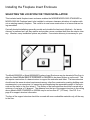
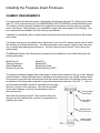
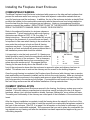
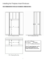
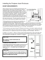
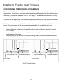
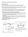
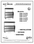
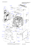
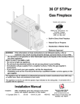
FIREPLACE INSERT ENCLOSURE
INSTALLATION INSTRUCTIONS
ENCLOSURE MODEL 90566400 FOR INSERT MODEL 5660NA
And
ENCLOSURE MODEL 90566000 FOR INSERT MODEL 5660 STANDARD
KEEP THESE INSTRUCTIONS FOR FUTURE USE
These products have been tested and listed to the standards UL127-2009 and ULC-S610-M87
Morsø US LLC
1011 Hwy. 52 West
Portland, TN 37148
TEL: (615) 323 0561
Report # 192-S-22-2/192-S-22b-2
INSTALLER: Leave this manual with the appliance.
CONSUMER: Retain this manual for future reference.
Installing the Fireplace Insert Enclosure
PRODUCT SAFETY
THESE FIREPLACE INSERT ENCLOSURES ARE A LISTED COMPONENT FOR AND ARE
INTENDED FOR USE WITH THE MORSØ MODELS 5660 STANDARD AND 5660NA WOODBURNING FIREPLACE INSERTS ONLY. DO NOT USE OTHER PRODUCTS NOT SPECIFIED OR
LISTED FOR USE WITH THESE ENCLOSURES.
WARNING:
IF THESE ENCLOSURES AND FIREPLACE INSERTS ARE NOT PROPERLY IN- STALLED, A
HOUSE FIRE MAY RESULT. TO REDUCE THE RISK OF FIRE, FOLLOW THE IN- STALLATION
INSTRUCTIONS EXACTLY. DO NOT ALLOW MAKESHIFT COMPROMISES TO ENDANGER
PROPERTY AND PERSONAL SAFETY.
CONTACT LOCAL BUILDING OR FIRE OFFICIALS ABOUT RESTRICTIONS AND
INSTALLATION INSPECTION REQUIREMENTS IN YOUR AREA.
IT IS A GOOD IDEA TO REVIEW YOUR PLANS WITH THEM BEFORE BEGINNING THE
INSTAL- LATION. ASK YOUR MORSØ AUTHORIZED DEALER FOR HELP WITH LOCAL
OFFICIALS IF NEEDED.
WHEN INSTALLLED IN THESE FIREPLACE INSERT ENCLOSURES IN THE UNITED
STATES, THE MORSØ MODELS 5660 STANDARD AND 5660NA FIREPLACE INSERTS
MUST ONLY BE CONNECTED TO ONE OF THE SPECIFIC CHIMNEYS LISTED ON PAGE 4
OF THIS MANUAL.
DO NOT CONNECT THIS UNIT TO A CHIMNEY FLUE SERVING ANOTHER APPLIANCE.
PLEASE READ THIS ENTIRE MANUAL BEFORE YOU INSTALL AND USE THE FIREPLAC INSERT ENCLOSURE AND MORSØ MODEL 5660 STANDARD OR 5660NA FIREPLACE
INSERT. FAILURE TO FOLLOW INSTRUCTIONS MAY RESULT IN PROPERTY DAMAGE,
BODILY IN- JURY OR EVEN DEATH.
FOR FURTHER INFORMATION, REFER TO THE NATIONAL FIRE PROTECTION
ASSOCIATION ANSI/NFPA 211 STANDARD FOR CHIMNEYS, FIREPLACES, VENTS AND
SOLID FUEL BURN- ING APPLIANCES.
REFER TO THE MORSØ MODEL 5660 STANDARD OR 5660NA OPERATING INSTRUCTIONS
FOR INFORMATION ON THE PROPER USE AND MAINTENANCE OF THE FIREPLACE
INSERT.
WARNING:
THIS FIREPLACE INSERT IS NOT A FIREPLACE. BUILDING A FIRE IN THE EN- CLOSURE
WITHOUT THE MORSØ MODEL 5660 STANDARD OR 5660NA INSTALLED IS PRO- HIBITED
AND MAY RESULT IN PROPERTY DAMAGE, BODILY INJURY OR EVEN DEATH.
2
Installing the Fireplace Insert Enclosure
SELECTING THE LOCATION FOR YOUR INSTALLATION
This insulated metal fireplace insert enclosure enables the MORSØ MODEL 5660 STANDARD or
MODEL 5660 NA Fireplace Insert to be installed in minimum–clearance situations in locations without an existing masonry fireplace. This could be in new home construction or in homes that are being remodeled.
Centrally located installations generally provide and circulate the heat most effectively. An interior
chimney is preferred as it will stay warmer and provide a more consistent draft than an exterior chimney. However, many installation options are possible. If an exterior chimney is necessary for your
The Model 90566000 or Model 90566400 Fireplace Insert Enclosure may be elevated off the floor to
allow the Insert Model 5660 STANDARD or 5660NA to be placed higher up on the wall. This
will require construction of a base structure to support the enclosure and insert. The base structure
should meet the same structural requirements as any other floor construction meeting building code
requirements in your area since it is supporting and transferring the appreciable weight of the enclosure and the Insert to the floor below it. The surface of the base structure should be covered with a
minimum of one layer of ¾ plywood. The distance from the top of the support structure to the ceiling
above Models 5660 STANDARD or 5660NA may be no less than 67” (1701mm). See FIG. 5 on
page 8 for support structure information.
The face of the support structure should be covered with non-combustible materials only, all the way
to the floor.
3
Installing the Fireplace Insert Enclosure
CHIMNEY REQUIREMENTS
For proper draft and best performance, the chimney should extend at least 15‟ (4.6m) and not more
than 35‟ (10.6m) above the level of the MORSØ Model 5660 STANDARD or Model 5660NA hearth.
The chimney must be properly installed and supported in accordance with the chimney manufacturer‟s instructions. The enclosure is not intended to support the entire weight of the chimney. Support components are available from the chimney manufacturer.
If possible, an installation with a straight vertical chimney will provide the best draft and will be easiest to clean.
If a straight chimney is not possible due to obstructions, up to four 30° elbows may be used to offset
the chimney around the obstructions. The elbows must be used in pairs in order to return the chimney to vertical after passing the obstruction. The first offset must be at least 8‟ (2.5m) above the
Insert hearth.
The Morsø Fireplace Insert Enclosures are approved for installation in the united States with the
following chimneys:
Metal Fab, Inc.
Security Chimneys
Selkirk Metalbest
Simpson-Dura-Vent
Model TG
Model ASHT
Model Ultra-Temp
Model Dura-Plus (SDP)
The chimney installation begins with a base plate or anchor plate mounted to the top of the Fireplace
Insert Enclosure. Before the base plate is installed on the enclosure top, the flexible stainless steel
flue connector (provided with the enclosure) that will connect the Insert to the chimney system must
be attached to the base plate using the four provided sheet metal fasteners. See FIG. 1. Next, insert the anchor plate/flex connector assembly down through
the hole in the top of the enclosure. Use the four provided
sheet metal fasteners to secure the base/anchor plate to
the enclosure top.
Chimney Base/
Anchor Plate
Next slide the stainless steel 45° slip connector elbow all
the way onto the stainless flex connector in preparation for
installing the Insert.
Sheet Metal
Fasteners
Stainless Steel
Flex Connector
Stainless Steel
45° Slip Elbow
FIG. 1
4
Installing the Fireplace Insert Enclosure
COMBUSTIBLE FRAMING
The Morsø Fireplace Insert Enclosure is designed with spacers on the side and back surfaces that
prevent the enclosure walls from coming in contact with adjacent combustible materials that are
used for framing around the enclosure. In addition, the top of the enclosure includes a standoff that
prohibits the header for the combustible construction above the enclosure from being installed too
close the heat from the Insert, enclosure top and chimney. Under no circumstances should the
spacers or standoff be modified. REDUCTIONS TO ANY OF THE REQUIRED CLEARANCES MAY
RESULT IN PROPERTY DAMAGE, BODILY INJURY OR EVEN DEATH.
Refer to the adjacent illustration for minimum clearance
requirements. Typical framing along with rough framing
dimensions are shown in FIGS. 2, 3 & 4 on page 7 of
these instructions. The actual framing details will vary depending on the placement of your enclosure and insert. It
is important to take care when framing to be sure that the
area under the enclosure is level and that all framing
members are plumb. Forcing the enclosure into a opening that is not level and plumb will cause problems later in
the installation process and should be avoided.
MINIMUM CLEARANCE TO COMBUSTIBLE
MATERIALS
It is important to note that only nominal 2 X 4 framing maA
10”
254mm
terials should be used to frame the area directly above the
B
2”
51mm
standoff on the front of the enclosure. This is necessary
C
3”
76mm
to prevent combustible framing from encroaching in the
D
67”
1702mm
space above the enclosure top. We suggest that the
E
29 1/4”
743mm
framing for the area directly above the standoff on the
front of the enclosure be done after the enclosure is secured in place and chimney has been installed. This allows room to work on the chimney and for access for the building inspector.
Once the rough framing is completed, the Fireplace Insert Enclosure (with chimney base or anchor
plate and flexible vent connector installed) can be slid into the rough opening. Make any last adjustments to center the enclosure in the opening and secure in place with at least four nails using the
pilot holes provide in the enclosure front flanges. Countersink the nail heads until they are flush with
the front flange surfaces as this will facilitate installation of facing materials later.
CHIMNEY INSTALLATION
With the Insert Fireplace Insert Enclosure secured to the framing, the chimney system may now be
installed. Follow the chimney manufacturer„s instructions exactly including the use of all support
hardware, elbows, joist, attic and insulation shields, firestops, flashing kits, storm collars and caps.
The safety and functionality of the chimney are critical parts of the installation of the enclosure and
Insert.
After the chimney installation is complete, install the framing above the standoff on the front of the
enclosure. This would be a good time to install the required non-combustible facing base material to
the front of the enclosure. See FIG. 6 on page 8 for information on the limits for placement of combustible and non-combustible materials. We recommend that you wait to place any combustible facing materials on any framing until after the installation has been inspected and approved by your local building inspector.
5
ELECTRICAL CONNECTIONS
If you are installing the Model 5660 NA with the optional blower, you must have electrical power connected to the single outlet provided on the side of Enclosure Model 95066400. Refer to the National
electrical Code, ANSI/NFPA 70 and other local code requirements. Use a licensed electrician. The
electrical specifications are 120 VAC, 60Hz, less than 1 amp.
OUTSIDE AIR
If the Outside Air Kit is to be installed, remove the Outside Air Cover Plate from the rear of the enclosure. This will allow the outside air duct to pass through the rear wall of the Fireplace Insert Enclosure.
VENTILATION AIR
The chase or cavity in which the enclosure is installed must be ventilated with air from outside of the
chase. A minimum of 24 square inches (154.8 square cm) of opening must be provided in the chase
wall no more than 24 inches (609 mm) from the floor of the chase. The opening may be located in
the floor of the chase between the enclosure and the walls of the chase. The opening may incorporate an architectural grate or grill as long as the 24 square inch opening is maintained.
WARNING
DO NOT PACK REQUIRED AIR SPACES WITH
INSULATION OR OTHER MATERIALS
INLET DUCTS FOR COMBUSTION AIR ARE NOT TO
TERMINATE IN ATTIC SPACES
6
Installing the Fireplace Insert Enclosure
RECOMMENDED ROUGH FRAMING DIMENSIONS
C
B
A
FIG. 2 Framing Front View
FIG. 3 Framing Side View
A = 67” (1702mm)
B = 39 3/4”
(1010mm)
C = 25 1/2” (648mm) Minimum
B
C
Note: These dimension are for
both Model 90566000 and
Model 90566400 Enclosures
FIG. 4 Framing Plan View
7
Installing the Fireplace Insert Enclosure
MINIMUM CLEARANCES TO ADJACENT COMBUSTIBLE MATERIALS
Combustible / Non-Combustible Material Limits
E = 39 3/4” (1010mm) F = 67” (1702mm)
G = 28 3/4” (730mm) J = 29 1/4” (742mm)
Ceiling
Model 5660
21 3/8” (543 mm)
16 3/8” (416mm)
H
K
Model 5660NA
26 1/8 “ (664)
11 5/8” (295)
E
D
Non-Combustible
Materials Only
J
D = 67”
(1702mm)
Minimum
F
G
H
Top of enclosure
support structure
when enclosure is
elevated off floor
K
FIG. 5
FIG. 6
FIG. 7
8
Installing the Fireplace Insert Enclosure
HEARTH REQUIREMENTS
When using the Insert in the Fireplace Insert Enclosure, the L = 39 3/4” (1010mm) Min.
hearth protection requirements are different than when inM = 16” (405 mm) Min. USA
stalling the Insert in an existing masonry fireplace. The en- N = 8” (203mm) Min.
closure has been designed to elevate the insert to the minimum distance above the combustible floor where no thermal
floor protection is required. However, unless the Fireplace
Insert Enclosure will be installed on a completely noncombustible surface such as unpainted concrete over earth,
N
spark and ember floor protection must be provided in front of
the insert and enclosure. This will protect the combustible
floor in front of the load door from spilled coals or embers.
N
M
L
The floor protector can be made from any completely nonFIG. 8
combustible material such as galvanized steel or noncombustible tile backer board. These materials may be covered with decorative non-combustible
materials such as ceramic tile. Other non-combustible materials may be used if there are no gaps or
joints between pieces that would allow coals or embers to reach the combustible floor underneath.
Floor protectors meeting the requirements of UL-1618 Type 1 are acceptable.
The floor protector must extend at least 8” (203mm) from the sides of the firebox opening making the
minimum total width of the floor protector 39 3/4“ (1010mm). In addition, the floor protector must extend a minimum of 16” (406mm) in front of the door opening in the United States. See FIG. 8.
In addition, a 3” X 39 3/4 “ (76mm X 1010 mm) sheet metal spark protector strip must be laid under
the junction between the front of the enclosure and the floor protector to prevent coals or embers
from reaching the combustible floor. See FIG. 7 on page 8.
CAUTION
12” (305mm)
Max. Depth
ONLY INSTALL HEARTH EXTENSION AS
ILLUSTRATED.
COMBUSTIBLE MANTEL
A combustible mantel and any associated trim may be mounted
to the wall above the Insert. The mantel (or trim) must be a
minimum of 24 1/4” (616mm) above the top flange on the
Insert. See FIG. 9. The mantel may not be deeper than
12” (305mm).
CAUTION
DO NOT PLACE INSULATION OR OTHER MATERIAL IN
REQUIRED CLEARANCE SPACES SURROUNDING THE
INSERT OR INSERT ENCLOSURE.
9
29 1/4”
(742mm)
FIG 9
Installing the Fireplace Insert Enclosure
CUSTOMIZING THE FINISHED APPEARANCE
The facing of the Fireplace Insert Enclosure may be finished to give a variety of different aesthetic
appearances. However, only non-combustible materials may be applied to the face inside the specified limits for combustible materials. See FIG. 6 on page 8. Outside the combustible limits, the any
surface finish may be used.
For a smooth wall appearance, non-combustible tile backer board may be used as a base for plaster
allowing a seamless transition beyond the combustible limits to traditional wallboard.
For tile, veneer brick or stone, the finish material may be applied over non-combustible tile backer
board. The requirements for the facing material applied inside the combustible limits are:
•
•
•
•
The material must be non-combustible.
The total thickness, including non-combustible backer board and adhesive should not exceed
13/16” (20mm).
Facing materials should not encroach into the front opening in the enclosure in order to allow
proper insertion of the Insert .
Combustible trim at the transition to combustible facing material must not protrude into the room
more than ¾” (19mm) from the facing material.
13/16” (20mm) Max.
Non-Combustible Tile
Backer Board
Insert Flange
13/16” (20mm) Max.
Non-Combustible Tile
Backer Board
Combustible Wallboard
or Tile Backer Board
Insert Flange
Non-CombustibleTile
FIG. 10 Facing Options
10
Combustible Wallboard
or Metal Lath
Plaster Skim Coat
Installing the Insert into the Enclosure
Prepare the Insert
Refer to the Morsø Installation and Operating Instructions for either Model 5660 NA Standard or
5669 NA with New Blower for instructions on how to prepare the insert for installation.
Follow the Blower Installation instructions on page 14 if you are installing the Insert with the optional
blower. Plug the blower power cord into the electrical outlet in the side of the enclosure. Route the
power cord between the insert stand and the enclosure side.
In order to connect the chimney to the insert it is necessary to remove the baffle and firebox liners.
It is not necessary to completely disassemble the insert. Do not remove the cast iron flue collar.
The instructions in the Morsø Insert manual will show you how to do this starting on page 6.
Install the Insert into the Fireplace Insert Enclosure
1. Using a helper or stove lifter, place the insert on the platform inside the enclosure. Push the insert back into the enclosure opening until the insert flange contacts the facing material. Check to
be sure the insert is centered in the enclosure opening.
2. Adjust the leveling screws until the face plate is level and plumb or aligned with any joints in the
facing material.
3. Reach up through the flue opening and pull down on the stainless steel 45° slip connector elbow
using the handle provided in the elbow. Make sure the connector elbow is full engaged in the
insert flue flange. See FIG. 11.
4. Bend the two tabs over to secure the connector elbow. See FIG. 12.
5. Replace the baffle using the reverse order for removal.
6. Replace the stones (firebrick).
7. Replace the door
Chimney Base/
Anchor Plate
Stainless Steel
Flex Connector
Stainless Steel
45° Slip Elbow
Flue Flange
FIG.12 Bending Flue Tabs
FIG.11 Cutaway View Showing Flue Connection
11
V1.US
12