1
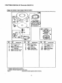
SE/AR_ Owner's Manual
C OMPANION I
5000 Watt
A-C Generator
Model No.
580.327112
CAUTION:
Before using this
product, read this manual and
follow all Safety Rules and
Operating Instructions.
HOURS:
SEARS,
Part No. B3051 .Draft 0 (7/23/98)
ROEBUCK
and
CO.,
Hoffman
Mon.-
Fri. 8 a.m. to 5 p.m. (CST)
Estates,
IL 60179
U.S.A.
WARRANTY ...............................
2
TROUBLESHOOTING .......................
13
SAFETY RULES ............................
3
WIRING DIAGRAM .........................
15
ASSEMBLY ................................
4
REPLACEMENT PARTS ..................
16-22
EMISSIONS WARRANTY
24-25
OPERATION .........................
t.y_3_
PRODUCT SPECIFICATIONS ..........
MAINTENANCE
STORAGE -..;
''
{'__i'
"_.":.":.":',
._., ._. ,'T_:',.
.:: .:-::-:-:::-:'
::":":_
L'iMi'TED ONE YEAR
_J
" ,.10
.................
HOW TO ORDER PARTS ............
BACK PAGE
:_i 'Jl'O.:li
.... _!!i:i;.12
WARRANTY
FOR COMPANION GENERATORS
SEARS warrants tO the Original purcl_aser that the alternator and engine for its portable generator will
be free from defects in materials or workmanship for the items and period set forth below from the
date of original purchase. This warranty is not transferable.
CONSUMER*
COMMERCIAL*
Alternator
Engine
1 year
1 year
90 Days
90 Days
"NOTE: For the purpose of this warranty "Consumer Use" means personal residential householdand
emergency use by original purchaser, not to be used as a primary source of power. "Commercial Use"
means all other uses, including rental, construction, commercial, and income producing purposes. Once
a generator has experienced commercial use, it shall thereafter be considered a commercial use
generator for the purpose of this warranty.
During said warranty period, SEARS will, at its option, repair or replace any part which, upon
examination by SEARS, is found to be defective under normal use and service**. Starting batteries
are not warranted by SEARS. All transportation costs under warranty, including return to the factory if
necessary, are to be borne by the purchaser and prepaid by him. This warranty does not cover
normal maintenance and service and does not apply to a generator set, alternator or engine, or parts
which have been subjected to improper or unauthorized installation or alteration, misuse, negligence,
accident, overloading, overspeeding, improper maintenance, repair or storage so as, in SEARS's
judgment, to adversely affect its performance and reliability.
** NORMAL WEAR: As with all mechanical devices, engines need periodic parts service and
replacement to perform well. This warranty will not cover repair when normal use has exhausted the
life of a part or engine.
THERE IS NO OTHER EXPRESS WARRANTY. SEARS HEREBY DISCLAIMS ANY AND ALL
IMPLIED WARRANTIES, INCLUDING BUT NOT LIMITED TO THOSE OF MERCHANTABILITY AND
FITNESS FOR A PARTICULAR PURPOSE TO THE EXTENT PERMITTED BY LAW. THE
DURATION OF ANY IMPLIED WARRANTIES WHICH CANNOT BE DISCLAIMED IS LIMITED TO
THE TIME PERIOD AS SPECIFIED IN THE EXPRESS WARRANTY. LIABILITY FOR
CONSEQUENTIAL, INCIDENTAL, OR SPECIAL DAMAGES UNDER ANY AND ALL WARRANTIES
IS EXCLUDED. Some provinces do not allow limitations on how long an implied warranty lasts, or
the exclusion or limitation of incidental or consequential damages, so the abovelimitations or
exclusions may not apply to you. This warranty gives you specific legal rights and you may also have
other rights, which vary from state to state.
For service, see your nearest SEARS authorized warranty service facility. Warranty service can be
performed only by a SEARS authorized service facility. This warranty will not apply to service at any
other facility. At the time of requesting warranty service, evidence of original purchase date must be
)resented.
SEARS,
ROEBUCK
and
CO.,
DI817WA,
2
Hoffman
Estates,
IL 60179
U.S.A.
CAUTION: Always disconnect spark plug
wire and place the wire where it cannot
contact the spark plug. To prevent
accidental starting when setting up,
transporting, adjusting or making repairs
to your Generator.
A
DANGER: This generator is designed for
outdoor use only. Do not use this
generator inside any building or
enclosure including the generator
compartment of a recreational vehicle
(RV). Fire or an explosion may result. No
user performed modifications, including
venting of exhaust and/or cooling
ventilation, will eliminate the danger.
Also, allow at least two feet of clearance
on all sides of the generator even while
operating the unit outdoors.
•
Gasoline is highly FLAMMABLE and itsvapors are
EXPLOSIVE. Do not permit smoking,open flames,
sparks or heat in the vicinity while handling gasoline.
Avoid spillinggasoline on a hot engine. Comply with
all laws regulatingstorage and handlingof gasoline.
•
Never add fuel while unit is running.
•
Do not overfillthe fuel tank. Always allow room for
fuel expansion. If tank is overfilled,fuel can overflow
onto a hot engine and cause FIRE or an EXPLOSION.
•
Never store generator with fuel in tank where gasoline vapors might reach an open flame or spark or
pilot light (as on a furnace, water heater or clothes
dryer). FIRE or an EXPLOSION might result.
•
Generator exhaust gases contain DEADLY carbon
monoxidegas. Operate this equipment only in the
open air where adequate ventilation is available.
•
The engine-generator requires an adequate flow of
coolingair for its continued proper operation. Never
operate the unit inside any room or enclosure where
the free flow of cooling air into and out of the unit
might be obstructed.Allow at least2 feet of clearance
on all sides of generator, even while operatingunit outdoors,or you coulddamage the unit.
•
Never start, or stop, the engine-generator with electrical loads connected to receptacles with the connected devices tumed ON. Start the engine and let it stabilize before connectingelectrical loads. Disconnect
all electrical loads before shuttingdown the generator.
•
Do not insert any object through coolingslots of the
engine-generator.
•
Never operate generator (a) in rain; (b) in any
enclosed compartment; (c) if connected electrical
devices overheat; (d) if electrical output is lost; (e) if
engine or generatorsparks; (f) if flames or smoke are
observed while unit is running;(g) if unitvibrates
excessively.
CAUTION: Before using this product,
read this manual and follow all Safety
Rules and Operating Instructions.
•
The generator produces dangerously high voltage
that can cause extremely hazardous electrical shock.
Avoid contact with bare wires, terminals, etc. Never
permit any unqualified person to operate or service
the generator.
•
Never handle any kind of electrical cord or device
while standing in water, while barefoot or while hands
or feet are wet.
•
The National Electric Code requires the frame and
external electrically conductive parts of generator be
properlyconnected to an approved earth ground.
Local electrical codes may also require proper
groundingof the generator. Consult with a local
electricianfor grounding requirements in your area.
•
Use a ground fault circuit interrupter in any damp or
highlyconductivearea (such as metal decking or
steel work).
•
Do not use any worn, bare, frayed or otherwise damaged electrical cord sets with the generator.
•
Operate generator only on level surfaces and where
it will not be exposed to excessive moisture,dirt, dust
or corrosivevapors.
Note: If you equipthe engine with a sparkarrestormuffler,
the spark arrestormustbe maintainedin effectiveworking
order bythe owner/operator.
In the State of Califomiaa spark arrestoris requiredby law
(Section4442 of the CaliforniaPublicResourcesCode).
Other states may have similarlaws. Federal lawsapply on
federal lands.The sparkarrestorpart numberfor this unitis
pin 34479A.
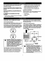
A
LOOK FOR THIS SYMBOL TO POINT OUT
IMPORTANT SAFETY PRECAUTIONS. IT
MEANS "ATTENTION!!! BECOME
ALERT!!! YOUR SAFETY IS INVOLVED."
Your A(3 generator requiressome assembly and is ready
for use after it has been properly serviced with the recommended oil and fuel.
If you have any problems with the assembly of your
generator, please call the generator helpline at 1-800222-3136
Important: Any attempt to run the engine before it has
been serviced with the recommended oil will resultin an
engine failure.
Carefully open the top flaps of the shippingcarton.
•
•
Cut down comers at one end of carton from top to
bottom and lay that side of carton down fiat.
Remove all packing material, carton fillers,etc.
•
Remove the generator from the shippingcarton.
CARTON
CONTENTS
Check all contents. If any parts are missing or damaged,
call the Generator Helpline at 1-800-222-3136.
TO REMOVE THE GENERATOR FROM
CARTON
•
The main unit
•
Owner's manual
•
•
Engine oil
Set the carton on a rigidflat surface with =THIS SIDE
UP" arrows pointing upward.
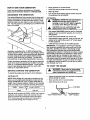
CORD SETS AND CONNECTOR
PLUGS
120 Volt Duplex Receptacle
Use only high quality, well-insulated, extension cords with
the generator's 120-volt duplex electrical receptacles.
Each receptacle is protected against overload by a pushto-reset circuitbreaker. Use each receptacle to operate
120 volts, single phase 60 Hz, A C electrical loads requiring up to 2400 watts (2.4 kW) at 20 amps of current.
Keep extension cords as short as possible, preferably
less than 15 feet long to prevent voltage drop and possible overheating of wires.
120/240 Volt, 20 AMP Receptacle
This receptacle is a NEMA L14-20R and is protected by a
push-to-reset circuit breaker. A NEMA L14-20P mating
connector plug is required to use this receptacle receptacle. Connect a suitable 4-wire cord set to the plug and to
the desired load. The cord set should be rated for 250
volts at 30 amps.
Ire Cord Set
(Neutral)
A
CAUTION! Although each receptacle is
rated for 120 volts at 20 amps (2400 watts
or 2.4 kW), the generator is rated for a
total of 5000 watts. Powering loads that
exceed the wattage capacity of the
generator can damage it or cause serious
injuries. The total of loads with 120 volts
powered through these receptacles
should not exceed 20 amps.
Check the ratings of all extension cords before you use
them. Extensioncord sets used should be rated 125 volts
at 20 ac amps or greater for most electrical devices.
Some devices, however, may not require this type of
extension cord. Check the owner's manuals of those
devices for the manufacturer's recommendations.
X (Hot)
Y (Hot)
1201240 VOLTS PLUG
A
(Green)
CAUTION! Although this receptacle is
rated for 240 volts at 20 amps (4800 watts
or 4.8 kwh, the generator is rated for a
total of 5000 watts (5.0 kW). Powering
loads that exceed the wattage capacity of
the generator can damage it or cause
serious injuries. Loads with 240 volts
powered through this receptacle should
not exceed 20 amps.
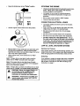
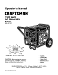
KNOW YOUR GENERATOR
Read the owner's manual and safety rules before operating your generator. Compare the illustrationswith your
Generator to familiarize yourself with the locationsof vadous controls and adjustments.
Fuel Tank
Muffler
Air Cleaner
Oil Fill Cap
120/240-Volt AC, 20 AMP
Locking Receptacle
/
120-Volt AC, 20 AMP
Duplex Receptacle
Oil Drain Plug
Circuit Breakers
120 Volt, 20 AMP, Duplex Receptacles -- May be used
to supply electrical power for the operation of 120 volts at
20 amps ac, single phase, 60 Hz, AC electrical lighting,
appliance, tool and motor loads.
120/240 Volt, 20 AMP, Locking Receptacle -- May be
used to supply electrical power for the operationof 120
and/or 240 volts at 20 amps AC, single phase, 60 Hz, AC
electrical lighting, appliance, tool and motor loads.
Air Cleaner -- Filters intake air as it is drawn through the
engine.
Choke Lever-
Used when starting a cold engine.
Circuit Breakers (AC) -- Each receptacle is provided
with a circuit breaker to protectthe generator against
electrical overload. Breakers are "pushto reset" type.
Fuel Tank -- Tank holds 5 U.S. gallons of unleaded
gasoline.
Muffler -- Muffler lowers engine noise.
Oil Drain Plug -- Drain engine oil here.
Oil Fill Cap -- Fill engine with oil here.
HOW TO USE YOUR GENERATOR
If you have any problemsoperating your Generator,
please call the Generator helpline at 1-800-222o3136.
GROUNDING
THE GENERATOR.
The National Electrical Code requires that the frame and
extemal electricallyconductiveparts of this generator be
properly connected to an approved earth ground. Local
electrical codes may also require proper groundingof the
unit. For that purpose, a groundinglug is provided on the
base of the cradle.
THE
Clean area around oil fill and remove oil fillcap
•
Wipe cap dean.
•
Pour oil into oil fill opening until oil reaches the point
of overflowing. Do not overfill!
•
Clean area around fuel fill cap, remove cap.
•
Add unleaded regular gasoline, slowlyto fuel tank. Be
careful not to overfill.Allow about 1/4" of tank space
for fuel expansion.
•
Install fuel cap and wipe up any spilled gasoline.
WARNING: Never start or stop engine
with electrical devices plugged into the
panel receptacles and turned on.
GENERATOR
_
CAUTION: Do not overfill the fuel tank.
Always leave room for expansion.
TO START THE ENGINE
Unplug all electrical loads from generator receptacles
before starting the engine.
NOTE: When adding oil to the engine crankcase in the
future, use only high quality detergent oil rated with API
service classificationSF or SG or higher rated SAE 30
weight. Use no special additives. Select the oil'sviscosity
grade according to your expected operating temperature.
32°F
A
Use regular UNLEADED gasoline with the Generator
engine. Do not use premium gasoline. Do not mix oil
with gasoline.
Add Engine Oil
-<-----
WARNING NEVER fill fuel tank indoors.
NEVER fill fuel tank when engine is
running or hot. DO NOT light a cigarette
or smoke when filling the fuel tank.
•
To operate the engine you will need to do the following:
colder
A
IMPORTANT: It is importantto prevent gum deposits
from forming in essential fuel system parts such as the
carburetor, fuel filter, fuel hose or tank during storage.
Also, experience indicatesthat alcohol-blendedfuels
(called gasohol, ethanol or methanol) can attract moisture
which leads to separation and formation of acids during
storage. Acidic gas can damage the fuel system of an
engine while in storage. To avoid engine problems, the
fuel system should be emptied before storage of 30 days
or longer. See "Storage"on page 12. Never use engine
or carburetor cleaner productsin the fuel tank or permanent damage may occur.
Proper groundingof generator will help prevent electrical
shock in the event of a ground fault condition in the generator or in connected electrical devices. Proper grounding also helps dissipate static electricity,which often
buildsup in ungrounded devices.
STARTING
Place generator on a level surface.
•
Add Gasoline
Generally, connecting a No. 12 AWG (American Wire
Gauge) stranded copper wire to the grounding lug and to
an earth-driven copper or brass grounding rod (electrode)
provides adequate protection against electrical shock.
However, local codes may vary widely. Consult with a
• local electrician for grounding requirements in your area.
BEFORE
•
•
,
Make sure the unit is in a level position.
Open the fuel shut--offvalve.
I
|
warmer
J..d.._
Fuel Tank
I
5W30
SAE 30
Turn Clockwise to
"OFF" Position
Although multi-viscosity oils (5W30, 10W30, etc.) improve
starting in cold weather, these multi-viscosity oils will
result in increased oil consumptionwhen used above
32°F. Check your engine oil level more frequently to
avoid possibledamage from runninglow on oil.
6
I
I
•
Move the choke lever to the "Choke"
I
STOPPING
position.
RUN
THE ENGINE
•
Unplug all electrical loads from generator panel receptacles. Never start or stop engine with electrical
devices plugged in and turned on.
•
Let engine run at no-load for several minutesto
stabilize the internal temperatures of engine and
generator.
°
°
Move engine control switch to "Off" Position.
Close the fuel shut-off valve
CONNECTING
t÷t
Set the engine controlswitch to the On position.
ELECTRICAL
•
Let engine stabilize and warm up for a few minutes
after starting.
•
Plug in and turn on the desired 120 and/or 240 volts,
single phase, 60 Hertz, A C electrical loads.
•
Do not connect 240 volts to the 120 volt duplex
receptacles
•
Do not connect 3-phase loads to the receptacles.
•
Do not connect any 50Hz loads to the receptacles.
•
DO NOT OVERLOAD THE GENERATOR. Add up
the rated watts (or amps) of all loads to be connected
at one time. This total should not be greater than the
rated wattage/amperage capacity of the generator.
See Don't Overload the Generator on Page 9.
LOW OIL LEVEL SHUTDOWN
•
•
If the system senses a low oil level during operation,the
engine shuts down. If the engine shuts down by itself and
it has enough gasoline in the fuel tank, check oil level.
When engine starts, move choke lever to "Run"
position.
Restarting
Note: If engine fails to start after 3 pulls, move the
choke lever to "RUN" and pull starter rope again.
If you attempt to restart the engine after such a shutdown
and have not corrected the engine oil level, the engine
will not start. Check the oil and refill accordingto the
instructionson page 7.
Note: If the engine fails to start after three (3) pulls,
check for proper oil level in crankcase. Unit is equipped
with a low oil shutdown system.
Note: If engine fires, but does not continue to run, move
choke lever to "Choke" and repeat starting instructions.
CAUTION!
engine indoors
in enclosed Never
poorly run
ventilated
areas. or
Engine exhaust contains carbon
monoxide, an odorless and deadly gas.
,_
WARNING! Temperature of muffler and
nearby areas may exceed 150°F (65°C).
Avoid these areas.
SYSTEM
Sensing Low Pressure
Manual Start: Grasp starter grip and pull slowly until
you feel some resistance. Then pull cord out with
rapid full arm stroke. Let rope retum slowly. Do not let
rope "snapback" against starter.
,_
LOADS
7
DON'T
OVERLOAD
THE
GENERATOR
..
Overloading a generator in excess of its rated wattage
capacity can result in damage to the generator and to
connected electrical devices. Observe the following, to
prevent overloading the unit:
,
Add up the total wattage of all electrical devices to be
connected at one time. This total should NOT be
greater than the generator's wattage capacity.
*
The rated wattage of lights can be taken from light
bulbs. The rated wattage of tools, appliances and
motors can usually be found on a data plate or decal
affixed to the device.
•
If the appliance, tool or motor does not give wattage,
multiply volts times ampere rating to determine watts
(volts x amps = watts).
WATTAGE
Electrical
REFERENCE
Some electric motors, such as inductiontypes,
require about two and a half times more watts of
power for startingthan for running. This surge of
power lasts only a few seconds when starting such
motors. Make sure you allow for this high starting
wattage when selecting electrical devices to connect
to your generator. First, figure the watts needed to
start the largest motor. Add to that figure the running
watts of all other connected loads.
The Wattage Reference Guide below is provided to
assist you in determininghow many items your generator
can operate at one time.
GUIDE
Device
Running
Watts
Electrical
Device
Running
Watts
Impact Wrench ................................................
500
*Air Conditioner
(12,000
Btu) .......................
1700
Battery Charger
(20 amp) ..............................
500
*Jet Pump ......................................................
Belt Sander (3") ...........................................
1000
Lawn Mower .................................................
Chain Saw ....................................................
1200
Light Bulb .......................................................
100
Microwave
700
Circular
Saw (6-12/") ........................
800 to 1000
800
1200
Oven ............................................
Coffee Maker ...............................................
1000
*Milk Cooler ..................................................
*Compressor
(1 HP) ....................................
2000
Oil Burner on Furnace ...................................
*Compressor
(3/4 HP) .................................
1800
Oil Fired Space Heater (140,000
*Compressor
(1/2 HP) .................................
1400
Oil Fired Space Heater (85,000
Btu) ............. 225
Curling Iron ....................................................
700
Oil Fired Space Heater (30,000
Btu) ............. 150
*Freezer
.........................................................
500
*Paint Sprayer, Airless (1/3 HP) ....................
600
Disc Sander (9") ...........................................
1200
Paint Sprayer, Airless (handheld) ..................
150
Edge Trimmer ................................................
500
1100
300
Btu) ........... 400
Radio ....................................................
50 to 200
Electric Nail Gun ..........................................
1200
*Refrigerator ...................................................
600
Electric Range (one element) ......................
1500
Slow Cooker ...................................................
200
Electric Skillet ...............................................
1250
*Submersible
Pump (1-1/2 HP) .................... 2800
*Furnace
1200
*Submersible
Pump (1 HP) ..........................
2000
Hair Dryer .....................................................
1200
*Submersible
Pump (1/2 HP) .......................
1500
Hand Drill (1") ..............................................
1100
Sump Pump ..................................................
Fan (1/3 HP) .................................
Hand Drill (1/2") ................................
750 to 1000
*Table Saw (10") .............................
600
1750 to 2000
Hand Drill (3/8") .............................................
500
Television ............................................
200 to 500
Hand Drill (1/4") .............................................
250
Weed Trimmer ...............................................
Hedge Trimmer ..............................................
450
* Allow 2-1/2 times the listed watts for starting
these devices.
500
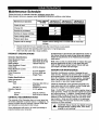
Maintenance Schedule
Follow the hourly or calendar intervals, whichever occurs first.
More frequent service is required when operating in adverse conditions noted below.
Every 5 Hours
or Ually
Maintenance Operation
Check oil level
25 Hours or
Every Season
50 Hours or
Every Season
100 Hours or
Every Season
X
Change oil_:
Service air pre-cleaner
Service air cleaner cartridge
Clean cooling system
X
Replace spark plug
X
Prepare unit for storage
Prepare unit for storage if it s to remain idle for more than
30 days
Change oil after first 5 hours of operationthen after every 25 hours or every season.
"
Change oil sooner when operating under heavy load or in high temperatures.
**
Clean more often under dirty or dusty conditions.
PRODUCT
SPECIFICATIONS
Generator Specifications
Rated Maximum Power .........
Surge Power .........
.......
Rated Voltage ...............
Rated Maximum Current
5000 Watts (5.0 kW)
6250 Watts (6.25 kW)
120/240 Volts AC
at 240 volts .................
Rated Maximum Current
20.8 AC Amperes
at 120 Volts ................
Rated Frequency ............
Phase .....................
41.7 AC Amperes
60 Hz at 3600 rpm
Single Phase
Engine Specifications
Rated Horsepower ...........
Spark Plug
Type: ................
Set Gap To: ...........
Gasoline Capacity ............
Oil
Summer .............
Winter ..............
GENERAL
10 at 3600 rpm
Champion RC14YC or
Equivalent
0.030inch (0.76mm)
5 U.S. gallons
SAE 30 (10W-30)
SAE 5W-20 or 5W-30
RECOMMENDATIONS
The warranty of the Generator does not cover items that
have been subjected to operator abuse or negligence. To
receive full value from the warranty, operator must maintain Generator as instructed in this manual.
Some adjustments will need to be made periodically to
properly maintain your Generator.
All adjustments in the Service and Adjustmentssection of
this manual should be made at least once each season.
Follow the requirements in the "Maintenance Schedule"
chart above.
Note: Once a year you should clean or replace the spark
plug and replace the air filter. A new spark plug and
clean air filter assure proper fuel-air mixture and help
your engine run better and last longer.
GENERATOR
MAINTENANCE
Generator maintenance consists of keeping the unit
clean and dry. Operate and store the unit in a clean dry
environmentwhere it will not be exposed to excessive
dust, dirt, moisture or any corrosivevapors. Cooling air
slots in the generator must not become clogged with
snow, leaves, or any other foreign material.
Check the cleanlinessof the generator frequently and
clean when dust, dirt, oil, moisture or other foreign substances are visible on its exterior surface.
Note: We DO NOT recommend using a garden hose to
clean generator. Water can enter the engine fuel system
and cause problems. In addition, if water enters the generator through cooling air slots, some of the water will be
retained in voids and cracks of the rotor and stator winding insulation. Water and dirt buildup on the generator
internal windingswill eventually decrease the insulation
resistance of these windings.
A
!
AUTION:theNever
Insert any
tool I
through
air cooling
slots,object
even or
if the
engine is not running.
Toclean.theGenerator•
....
Use a damp clotht0 Wipeexterior surfaces Clean.
•
A soft, bristle brush may be used to loosen caked on
dirt, oil, etc.
•
A vacuum cleaner may be used to pick up loose dirt
and debris.
" SERVICE AIR
.... CLEANER"'
_
Your engine will not run properly and may be damaged if
you run it using a dirtyair cleaner.
Clean or replace the foam pre-cleaner every 25 hours of
operation. Service cartridgeevery 100 hours of operation
or once a year, whichever comes first. Clean or replace
more often if operating under dusty or dirty conditions.
Replacements are available at your local Sears
Authorized Service Center.
Low pressure air (not to exceed 25 psi) may be used
to blow away dirt. Inspect cooling air slots and openings on the generator. These openings must be kept
clean and unobstructed.
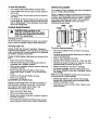
ENGINE MAINTENANCE
A
DANGER: When working on the
generator ALWAYS disconnect spark
plug wire from spark plug and keep it
away from spark plug.
Checking Oil Level
Oil level should be checked prior to each use or at least
every 5 hours of operation. Keep oil level maintained.
Changing Engine Oil
Change oil after first 5 hours of operation. Change oil
every 25 hours thereafter. If you are using your generator
under extremely dirty or dusty conditions, or in extremely
hot weather, change oil more often.
To
service foam pre-cleaner:
•
The cover is attached to the air cleaner housing by
two screws.
•
Carefully remove air cleaner assembly from inside of
cover and disassemble.
Change oil while engine is still warm from running, as follows:
•
Wash in liquid detergent and water.
•
•
Clean area around oil drain plug.
Remove oil drain plug and oil fill plug and drain 0il
completely into a suitable container.
•
•
Squeeze (don't twist) pre-cleaner in a clean, dry cloth.
Saturate pre-cleaner in engine oil. Squeeze in a clean
absorbent cloth to remove all excess oil.
•
When oil has completely drained, Install oil drain plug
and tighten securely.
•
Fill oil sump with recommended oil. (See "Before
Starting the Engine" on page 7 for oil recommendations)
Change the spark plug every 100 hours of operation or
once each year, whichever comes first. This will help
your engine to start easier and run better. See
"Specifications" for proper spark plug.
Clean area around spark plug.
•
Remove and inspect spark plug.
•
Replace spark plug if electrodes are pitted, burnedor
porcelain is cracked.
•
Check electrode gap with wire feeler gauge and set
spark plug gap to 0.030 inch (0.76ram) if necessary.
Replace pre-cleaner if very dirty or damaged.
To service cartridge, clean by tapping gently on a
flat surface. Replace if very dirty or damaged. Do not
oil cartridge.
Note: Do not use petroleumsolventssuch as kerosene,
or pressurized air to clean cartridge.
• Install the oil fill plug and tighten securely.
• Wipe up any spilled oil.
CLEAN/REPLACE SPARK PLUG
•
•
•
10
•
Reassemble retainer on pre-cleaner and cartridge
(screen side of pre-cleaner toward cartridge pleats).
Install this assembly in cover.
•
Insert tabs on cover into slots in base. Tighten cover
screws securely.
KEEP ENGINE AND PARTSCLEAN
With a brush or cloth, remove debris from debris guard or
rotatingscreen daily or more often if needed to prevent
engine damage caused by overheating. Do not clean with
a forceful spray of water because water could contaminate the fuel system.
Keep governor linkage, springs, and controlsfree of
debris. Debris or chaff may clog the air cooling system,
especially after prolonged operation. Remove blower
housing and clean area shown to prevent overheating
and engine damage.
CLEAN
OUT
DEBRIS
AND
CHAFF
GENERAL
• Run engine until engine stops from lack of fuel.
CHANGE OIL
The generator should be started at least once every
seven days and allowed to run at least 30 minutes. If this
cannot be done and you must store the unitfor more
than 30 days, use the following informationas a guide to
prepare it for storage.
LONG TERM STORAGE
A
While engine is still warm, drain oil from crankcase. Refill
with recommended grade.
OIL CYLINDER BORE
•
INSTRUCTIONS
WARNING: NEVER store engine with fuel
in tank indoors or in enclosed, poorly
ventilated areas where fumes may reach
an open flame, spark or pilot light as on a
furnace, water heater, clothes dryer or
other gas appliance.
Remove spark plug and pour about 1/2 ounce (15ml)
of engine oil into the cylinder. Cover spark plug hole
with rag. Crank slowlyto distributeoil.
IA
CAUTION'
Av°id spray
fr°mslowly.
spark plug
hole
when cranking
engine
•
Install spark plug. Do not connect spark piug wire.
GENERATOR:
It is importantto prevent gum depositsfrom formingin
essential fuel system parts such as the carburetor,fuel
filter, fuel hose or tank during storage. Also, experience
indicates that alcohol-blended fuels (called gasohol,
ethanol or methanol) can attract moisture which leads to
separation and formation of acids duringstorage. Acidic
gas can damage the fuel system of an engine while in
storage.
•
Clean the generator as outlined on Page 10 ("To
Clean the Generator").
•
Check that cooling air slots and openings on generator are open and unobstructed.
•
Do not store gasoline from one season to another.
To avoid engine problems, the fuel system shouldbe
emptied before storage of 30 days or longer. Follow
these instructions:
•
Replace your gasoline can if your can starts to rust.
Rust and/or dirt in your gasoline will cause problems.
•
If possible, store your unit indoors and cover it to give
protection from dust and dirt. BE SURE TO EMPTY
THE FUEL TANK.
PROTECT
A
•
I
OTHER STORAGE TIPS:
FUEL SYSTEM
Cover your unit with a suitable protective cover that
does not retain moisture.
WARNING: Drain fuel into approved
container outdoors, away from open
flame. Be sure engine is cool. Do not
smoke.
•
Store generator in clean, dry area.
I A
Remove all gasoline from the fuel tank to prevent gum
deposits from forming on these parts and causing
possible malfunction of engine.
I]
while
engine and exhaust area are warm.
DANGER:NEVERcoveryourGenerator
i
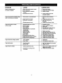
PROBLEM
Engineisrunning,butno
ACoutputisavailable.
Engineruns goodat no-loadbut "bogs
down"whenloadsare connected
CORRECTION
CAUSE
1.Oneof thecircuitbreakers isopen.
2.Faultin generator.
3.Poorconnection
or defective
cordseL
4.connecteddeviceisbad.
1. Resetcircuitbreaker.
2. ContactSearsServiceFacility.
3. Checkandrepair.
1.Shortcircuitina connectedload.
1. Disconnect
shortedelectrical
load.
2. ContactSearsServiceFacility.
3. See=Don_Overloadthe
Generator"
4. ContactSearsServiceFacility.
2.Enginespeedis tooslow.
3.Generator
isoverloaded.
4.Shortedgeneratorcircuit.
Enginewillnot start; or starts
and runs rough.
1.Run/StopSwitchset to STOP.
2.Dirty aircleaner
3.Outof gasoline.
4.Stalegasoline.
5.Sparkplug wirenot connected
to sparkplug.
6.Badspark plug.
7.Waterin gasoline.
8.overchoking.
9.Lowoillevel
10.Excessivelyrichfuel mixture.
11.Intakevalvestuck open or closed.
12.Enginehaslost compression.
4. Connectanotherdevicethat
is in good condition.
1.
2.
3.
4.
5.
6.
7.
8.
9.
10.
11.
12.
Setswitchto RUN.
Cleanor replaceair cleaner.
RIIfuel tank.
Draingas tank;fill withfresh fuel.
Connectwireto spark plug.
Replacespark plug.
Draingastank;fill withfresh fuel.
Openchokefully andcrankengine.
RII crankcase
to properlevel.
ContactSearsServiceFacility.
ContactSearsServiceFacility.
ContactSearsServiceFacility.
Engineshuts downduringoperation
1.Outof gasoline.
2iow oil level.
1. Fillfueltank.
2. Fillcrankcase
to properlevel.
Enginelackspower.
1.Loadis too high.
2.Dirtyair filter.
1. See =Don'tOverloadthe Generator"
2. Replaceair filter.
Engine=hunts"or falters.
1.Chokeis openedtoo soon.
1. Movechoketo halfwaypositionuntil
engineruns smoothly.
.
ContactSearsServiceFacility.
2.Carburetoris runningtoo rich
or too lean.
]2
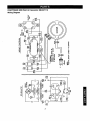
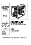
CRAFTSMAN
5000 Watt AC Generator 580.327112
Wiring Diagram
r__L_
_d
I_
_/
i
Ii
n,'o
o
_glll
II II
_________J
÷
,_ r U L_-_
cJ
<{
o
13
I
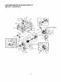
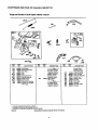
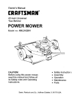
CRAFTSMAN
5000 Watt AC Generator 580,327112
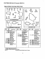
Main Unit -- Exploded View
44 _
66
59
• X " (STOP SVITCH
900
51
38=
55
tO,,
13
15
35
14
II
49
2
25
21
-36
TO • A •
26
22
14
TERMINAL)
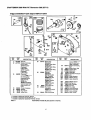
CRAFTSMAN
Main UnitITEM
900
5000 Watt AC Generator
580.327112
Parts List
PART NO.
91011
Q_.
1
2
4
5
91020B
143-53621
86292
1
1
1
6
7
8
10
11
12
75475
70642
22129
38150
93585J
66365G
4
2
8
4
1
1
13
14
15
16
19
91844
65791
47480
81917
86308C
1
1
1
1
4
20
21
22264
66849
4
2
22
86494
1
23
68759
1
24
94396B
1
25
95600
1
26
91825
1
27
28
67451
23365
1
4
29
30
51715
74908
4
4
31
26850
2
32
84242
2
33
86307
4
34
67022
1
35
36
52858
22769
6
1
DESCRIPTION
ENGINE, Briggs &
Stratton 10 Hp
ASSEMBLY, Cradle
WIRE, Ground
CAPSCREW, #10 Self
Driller
SCREW, M4-0.7 x 10ram
MOUNT, Vibration
WASHER, M8 Lock
WASHER, No. 8 Flat
ASSEMBLY, Stator
HOUSING, Engine
Adapter
ASSEMBLY, Rotor
BEARING, Ball
BOLT, Rotor 5/16"-24 x 7"
PIN, M4 x 10 Roll
BOLT, Stator M6-1.00 x
130ram
WASHER, No. 8 Lock
SCREW, M5- .80 x 16ram
Taptite
SCREW, M6 x 16mm
Wing
RECEPTACLE, 120Volts
AC, 20AMP
BREAKER, Circuit20AMP
PANEL, Control Sheet
Metal
ASSEM, Brush & Bridge
Rectifier
WASHER, Flat (Special)
WASHER, No.8
Shakeproof
NUT, M4-0.7 Hex
SCREW, M5- 0.80 x
10ram
WASHER, Shakeproof 1/4"
GROMMET, Rear Bearing
Carrier
CAPSCREW, Hx Hd.5116" x 3/4"
GROMMET, Bearing
Carrier
NUT, M8-1.25 Hex
WASHER, No. 10
Shakeproof
ITEM
37
38
PAFITNO.
22145
68867
QTY.
2
1
39
76222
2
40
41
48031C
83465
2
4
44
78831B
4
46
47
48
49
50
51
52
53
54
55
90878
82857
25244
66825C
77374
78299
80270
77395
78951
56892
1
2
2
1
1
1
1
4
1
2
56
88977
1
57
58
91841
91842
1
1
59
32713
2
60
61
22471 ....
23365
2
1
62
63
64
B3050
98247
94396A
1
1
1
65
66
92982
93826
1
1
DESCRIPTION
WASHER, M8 Flat
OUTLET, 120/240 Volt Twistlock
SCREW, Pan Head-M8 x
40ram
CLAMP, 1/4" Hose
GROMMET, Mounting
Tank
CAPSCW., Hx Hd.-M61.0 x 60mm
CAP, Fuel Tank
MOUNT, Vibration
NUT, 5/16" - 18 Hex
BEARING, Rear Carder
TANK, Fuel
BUSHING, Plastic Tank
VALVE, Plastic Tank
NUT, M6 Hex Lock
SHIELD, Heat
SCREW, Crimptite #10-24
x 3/8"
SWITCH, Low Oil ShutDown (LOS)
GASKET
WIRE, Low Oil ShutDown
SCREW, No. 10-32 x 3/4"
Taptite
NUT, No. 8-32
WASHER, No. 8
Shakeproof
DECAL, Panel Cradle
DECAL, Control Panel
BREAKER, Circuit 15
AMP
DECAL, Danger
DECAL, Operating
Instructions
Parts Not Illusbated
B3051
1
Owner'sManual
B3061
2
2007_EngineOil
Optional Accessories Not Illustrated
09-32684
Wheel I_t
O9-32688
Cord Wrap I_t
O9-32686
120/240V 20A Rug
]5
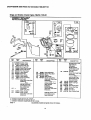
CRAFTSMAN
5000 Watt AC Generator
580.327112
Briggs and Stratton 4 Cycle Engine 19G412-1129-E1
z
7
3O6
13
552
5
10
I 1058 OWNER'S
REF.
NO.
PART
NO.
495631
MANUAL
J[ 1019 LABEL
REF.
NO.
DESCRIPTION
Cylinder Assembly
(Includes OIL GARD®
Cover)
2
3
5
7
8
495657
*391085
214347
_272163
495736
9
10
11
*27803
94621
280225
11A
231900
Bushing
Seal-Oil
Head-Cylinder
Gasket-Cylinder Hd.
Breather Assembly
(Used After Code Date
95010100).
Gasket-Breather
Scfew-Sem
Tube-Breather
(Used After Code Date
95010100).
Tube-Breather
(Used Before Code
Date 94111100).
KIT
PART
NO.
I 9r REQUIRES SPECIAL TOOLS TO INSTALL.
SEE REPAIR
DESCRIPTION
13
94565
13A
94733
14
93723
15
33
94239
390419
Screw-Cylinder Head
(3-9/16" Long)
Stud-Cylinder Head
Used in Position # 5 &
#6.
Screw-Cylinder Head
(3" Long)
Plug-Oil Drain
Valve-Exhaust
34
261055
(Indudes Fief. 42)
Valve-Intake
35
65906
36
26828
40
41
42
306
307
308
221596
292260
494553
496797
94386
225055
Spring--Valve
(Intake)
Spring-Valve
(Exhaust)
Retainer-Valve
Retainer-Valve
Keeper-Valve
Shield--Cylinder
Screw-Sell' Tapping
Cover-Cylinder Head
INSTRUCTION
REF.
NO.
337
354A
383
529
552
635
869
871
MANUAL.
PART
NO.
496018
94726
89838
281367
DESCRIPTION
Plug-Spark
Nut-Hex.
Wrench-Spark Plug
Grommet
(Used Before Code
Date 94111100).
491986 Bushing--Gov. Crank
66538 Boot-Spark Plug
211661 Seat-Valve
261961 Bushing-Guide
(Exhaust)
1019
1058
491181
272848
Note
231218 BushingGuide
(Intake)
Label Kit
Owner's Manual
, Included in Gasket Set-Part No. 497070.
• Included in Carburetor Kit-See Rel. No. 121.
4, Included in Carburetor Gasket Set-Part No. 497069.
0432-2
Assemblies include all parts shown in frames.
]5
25
CRAFTSMAN
5000 Watt AC Generator 580.327112
Briggsand Stratton 4 Cycle Engine19G412-1129-E1
26
219
_:_186
12
3
f If'_\\
230
592
REF.
NO.
3
12
16
PART
NO.
*391086
*271701
DESCRIPTION
Seal-Oil
Gasket-Crankcase
(.015" Thick)
,27876 GasketCrankcase
(.005" Thick)
,27877 GasketCrankcase
(.009" Thick)
495832 Crankshaft
Note
REF.
NO.
25
PART
NO.
391673
18
19
21
22
496984
295964
66768
93585
Bushing
Plug-Oil Fill
Screw-Sem
REF.
NO.
Piston Assy.
(Standard)
391674 Piston Assy.
(.010" O.S.)
391675 Piston Assy.
(.02o-o.s.)
26
393881
391676 Piston Assy.
(.030" O.S.)
Ring Set
(Standard)
299743 Ring Set
(Std.. Chrome)
393882 Ring Set
For "13ruing
Gear
Retaining Device.
Order Part No.
94388 Key.
495790 Crankshaft
Used on Type No(s).
0068, 0129, 0131,
0169.
Cover-Crankcase
DESCRIPTION
(.OlO-O.S.)
393883 Ring Set
(.020" O.S.)
393884 Ring Set
(.030"O.S.)
27
28
68546 Lock-Piston Pin
295840 Pin-Piston
(Standard)
295841 Pin-Piston
29
390401
(.005"O.S.)
Rod-Connecting
* Included in Gasket Set-Part No. 497070.
• Included in Carburetor Kit-See Ref. No. 121.
€ Included in Carburetor Gasket Set-Part No. 497069.
0432-3
Assemblies include all parts shown in frames.
17
30
PART
NO.
DESCRIPTION
Note
390773 Rod-Conn.
(.020" Undersize)
222113 Dipper-Connecting
Rod
32
45
46
84
186
202
219
220
227
94670
260933
211689
9'1488
67218
263049
497037
221551
496254
Screw-Conn. Rod
Tappet-Valve
Gear-Cam
23O
232
562
592
614
616
623
624
741
94742
26302O
92613
231082
93306
496818
231520
497207
262479
WasHer-Thrust
Plug-Pipe
Connector-Fuel Line
Link
Gear--Governor
Washer-Thrust
Lever-Governor
Spring-Link
Bolt-Carriage
Nut-Hex.
Pin-Cotter
Crank-Governc¢
•Screw-Shoulder
Lever-Linkage
Gear-'13ming
CRAFTSMAN
5000 Watt AC Generator
580.327112
Briggs and Stratton 4 Cycle Engine 19G412-1129-E1
REQUIRES SPECIAL TOOLS
TO INSTALL.
SEE REPAIR
INSTRUCTION
MANUAL.
95
987
52
REF.
NO.
PART
NO.
51 e,,272708
52 ,272707
53
94778
93 t281346
95
e94098
98
495800
104 t231789
105 D231935
106 e231856
108
224666
116
494383
123
94616
125
497844
127
130
131
*
•
.
Gasket-Intake
Gasket-Intake
Stud-Carb. Mtg.
Bushing-Shaft
Screw-Round Head
Screw-Idle Adjust
Pin-Float Hinge
Valve-Needle
Seat-Inlet
Valve-Choke
Valve-Needle
Screw-Torx®Hex.
Carburetor
(Used After Code Date
94083100)o
Note
497164 Carburetor
(Used Before Code
Dale 94090100).
•
Plug-Welch
(Sold in Kit Only)
224539 Valve-Throttle
497846 Shaft-Throttle
(Used After Code Date
94083100).
Included
Included
Included
0432-4
REEF.
NO.
DESCRIPTION
PART
NO.
DESCRIPTION
REF.
NO.
PART
NO.
DESCRIPTION
497198 Nozzle-Carb.
147
133
494381
137 o,281165
138 e+281164
141
497160
142 e497564
o497472
Roat-C_,buretor
Gasket-Float Bowl
Washer
Shaft-Choke
Nozzle-Carburetor
(Used Afler Code Date
94062300).
Note
497848 Nozzle-Carb.
164
186A
(High Altitude)
Include(s):
281164 Washer
(Used After Code Date
94062300).
e497197 Nozzle-Carb.
(Used Before Code
Date 94062400).
in Gasket Set-Part
No. 497070.
in Carburetor Kit-See Ref. No. 121.
in Carburetor Gasket Set-Part
No. 497069.
Assemblies include all parts shown in frames.
]8
618
634
955
965
975
987
(High Altitude)
Include(s):
281164 Washer
(Used Before Code
Date 94062400).
Jet-Pilot
(Used After Code Date
94072400).
Note
e231794 Jet-Pilot
214170
(Used Before Code
Date 94072500).
Manifold-Intake
493496
Elbow-Fuel Pipe
e262803 Spring
•2.81168 Seal-Choke Shaft
94642 Screw-Bowl Mtg.
94010 Nut-Hex.
494379 Bowl-Float
e281166 Seal-Throttle Shaft
CRAFTSMAN
5000 Watt AC Generator 580.327112
Briggs and Stratton 4 Cycle Engine 19G412-1129-E1
63
@1
REF.
NO.
*
•
•
PART
NO.
55
393576
56
57
58
295871
490179
65884
59
60
490653
490652
REF.
NO.
DESCRIPTION
PART
NO.
DESCRIPTION
Housing-Rewind
Starter
Pulley-Starter
Swing-Rewind Starter
Rope-Starter
63
64
260414
230543
65
66
94128
399671
Screw-Sem
Clutch-StaRer
(63"Long)
67
68
394897
63770
Housing-Clutch
Bali-Starter Clutch
Insert-Starter Handle
Grip-Starter Rope
REF.
NO.
70
Spring-Ratchet
Adopter-Ratchet
Spr_j
71
373
608
655
1018
Included in Gasket Set-Part No. 497070.
Included in Carburetor Kit-See Ref. No. 121.
Included in Carburetor Gasket Set-Part No. 497069.
0432-5
Assemblies
include
all parts shown
]9
in frames.
PART
NO.
DESCRIPTION
298799
Ratchet-Rewind
Starter
394506 Washer-Retainer
92987 Nut-Hex.
390391 Starter-Rewind
222598
490617
Anchor-Spring
Spacer
CRAFTSMAN
5000 Watt AC Generator 580.327112
Briggsand Stratton4 Cycle Engine 19G412-1129-E1
201
°
17sAi
209
209A
•
_271
269_'__
_
268
RER
NO.
PART
NO.
75A
98A
165
201
201A
209
209A
222
232A
258
268
495659
493280
94692
263051
262970
263054
260723
497076
262959
94620
65616
DESCRIPTION
Kit-Washer
Swing-Speed Adj.
Nut-Wing
Link
Link
Spring--Governor
Spdng-Govemor
Plate-Control
Spring-Link
Screw-_elf Tapping
Casing-Control Wire
(72" Long)
REF.
NO.
PART
NO.
DESCRIPTION
REF.
NO.
Note
If Longer Casing is
Required, Specify
Length in Inches; if
Shorter Casing is
Needed, Cut to
Required Length.
26633 W'_e-Control
269
(78" Long)
Note /
If Longer Wire is
Required. Specify
Length in Inches; if
. Included in Gasket Set-Part No. 497070.
• Included in Carburetor Kit-See Ref. No. 121.
. Included in Carburetor Gasket Set-Part No. 497069.
0432-6
Assemblies
include
all parts shown in frames.
2O
PART
NO.
27O
DESCRIPTION
Shorter Wire is
270
271
333
334
353
354
356
520
851
985
63426
290568
492341
94731
92791
90576
491391
93722
493880
396525
Needed, Cut to
Required Length.
Locknut-Casing
Lever-Control
Armature-Magneto
Screw-.Hex.
Washer-I.,ock
Nut-Hex.
Wire--Stop
Terminal
Terminal-Cable
Insulator
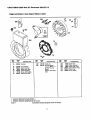
CRAFTSMAN
5000 Watt AC Generator 580,327112
Briggs and Stratton 4 CycleEngine19G412-1129-E1
24
\
_305
423
23
304
75
_
REF
NO
PART
NO
23
298260
Flywheel
24
37
38
222698
222475
94811
Key-Flywheel
Guard-Flywheel
Screw-Hex
Head
73
74
75
224874
93758
224061
Screen-Rotating
Screw-Self
Tapping
Washer-Flywheel
Included
• Included
_, Included
0432-7
DESCRIPTION
RER
NO
2OO
3O4
PART
NO
221760
491596
73
DESCRIPT_N
Guide-Air
Housing-Blower
Note
491592 HousingBlower
Used on Type No(s).
0169,
REF
NO
305
363
423
575
726
727
in Gasket Set-Part No. 497070.
in Carburetor Kit-See Ref. No. 121.
in Carburetor Gasket Set-Part No. 497069.
Assemblies include all parts shown in frames.
21
PART
NO
94786
19203
94625
396691
392134
395405
DESCRIPTION
Screw-Hex
Puller-Rywheel
Screw-Hex Head
Switch-Rotary Stop
Gear-Ring
Cover-Starter
CRAFTSMAN
5000 Watt AC Generator 580.327112
Briggs and Stratton 4 Cycle Engine 19G412-1129-E1
843
969
529A_
258 _1_
163
445
RER
NO.
PART
NO.
53A
94706
81 " 222263
163 *272706
258
94620
300
391370
346
445
467
.
•
93705
496077
280715
DESCRIPTION
Screw--Sem
Lock-Muffler Screw
Gasket-Air Cleaner
Screw-Self Tapping
Muffler-Exhaust
REF.
NO.
PART
NO.
529A
613
642
843
864
883
966
281368
94042
281357
280149
497140
*272309
497669
Screw-Sem
Rlter-Air
Knob
159
642
REF.
NO.
DESCRIPTION
Grommet
Screw-Muffler
Cover-Air Cleaner
Sleeve-Lever
Adapter-Muffler
Gasket-Exhaust
Base-Air Cleaner
969
994
(Used After Code Date
95010100),
Induded in Gasket Set-Part No. 497070.
Included in Carburetor Kit-See Ref. No. 121.
Induded in Carburetor Gasket Seb-Part No. 497069.
0432-8
Assemblies
include
all parts shown
22
in frames.
PART
NO.
DESCRIPTION
Note
496247 Base-Air
Cleaner
(Used Before Code
Date 95010200).
94777 Screw-Air Cleaner
391913 Arrester-Spark
CRAFTSMAN
5000 Watt AC Generator
580.327112
Briggsand Stratton 4 Cycle Engine19G412-1129-E1
G
978
982
957
_P
601
959
387
188
REF.
NO.
116
187
PART
NO.
280203
393815
_,_
REF.
NO.
DESCRIPTION
Seal-O-Ring
Line-Fuel
(11" Long, Cut to Suit)
Note
296004 Line-Fuel
187A
188
240
346
353
354
385
497029
94627
394358
93705
92791
90576
94789
(28" Long, Cut to Suit)
Line-Fuel
Screw-Sere
Filter-Fuel
Screw-Sere
Lockwasher
Nut-Hex.
Screw-Hex. Head
188
PART
NO.
REF.
NO.
DESCRIPTION
387
601
729
918
496257
93053
223528
497547
Pump-Fuel
Clamp-Hose
Clip-Wire
Line
948
956
398661
493337
Harness-Wiring
Tank-Fuel
957
958
959
493988
399517
495664
Cap-Fuel Tank
Valve-Shut-Off
Bracket-Fuel Tank
Include(s):
94733 Stud-Cyl. Hd,
94726 Nut-Hex.
960
961
978
979
980
982
982A
983
984
* Included in Gasket Set-Part No. 497070.
o Included in Carburetor Kit-See Ref. No. 121.
_, Included in Carburetor Gasket Set-Part No. 497069.
0432-9
Assemblies
include
all aarts
23
shown
in frames.
PART
NO.
DESCRIPTION
492990
94095
_271736
494807
398182
94657
94658
Bracket-Fuel Tank
Screw-Hex. Head
Gasket
Cover-OIL GARD®
OIL GARD® Kit
Screw-Hex. Head
Screw-Hex. Head
398660
223773
Light-Indicator
Bracket-Light
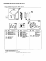
CRAFTSMAN
5000 Watt AC Generator
580.327112
Briggs and Stratton 4 Cycle Engine 19G412-1129-E1
ii
127
138
106
987
95
93
3
978
e
(D
137
6
1!5
14_7
634
142_
cD 618
121 CARBURETOR
O138
O137
977 CARBURETOR
RER
NO.
PART
NO.
883
KIT
358 GASKET
GASKET SET
RER
NO.
DESCRIPTION
3
,391086
Seal-Oil
7
9
12
.272163
.27803
.271701
Gasket--Cylinder Hd.
Gasket-Breather
Gasket-Crankcase
(.015" Thick)
.27876 GasketCrankcase
PART
NO.
127
•
137 e.281165
138 e.281164
142 o497564
93
95
e281348
o94098
Bushing-Shaft
Screw-Round Head
104
105
106
121
'e231789
e231935
0231856
497849
(Used Before Code
Date 94062400).
Rug-Welch
(Sold in Kit Only)
Gasket-Roar Bowl
Washer
Nozzle-Carburetor
(Used After Code Date
94062300).
Note
497848 NozzJe-Carb.
(High A)'Jtude)
Include(s):
281164 Washer
(.oo9-Thk:k)
Gasket-Intake
Gasket-Intake
Pin-FloatHinge
Valve-Needle
Seat-inlet
Carburetor Kit
(Used After Code Date
94062300).
Assemblies
Include
(High Altitude)
Include(s):
281164 Washer
(Used Before Code
147
Date 94062400).
1,497472 Jet-Pilot
(Used After Code Date
94072400).
Note
e231794 Jet-Pilot
{Used After Code Date
94062300).
*272706
497070
o282803
e281168
e497197 Nozzle-Cart).
(Used Before Code
Date 94062400).
883
977
978
987
*272309
487069
*271736
e2.81166
all parts shown
24
in frames.
DESCRIPTION
497198 Nozzle-Carb.
163
358
618
634
. Included in Gasket Set-Part No. 497070.
• Included in Carburetor Kit-See Ref. No. 121.
• Included in Carburetor Gasket Set-Part No. 497069.
0432-12
PART
NO.
_.
Note
497166 Carburetor Kit
(.005" Thick)
.27877 GasketCrankcase
51 e,272708
52 .272707
RER
NO.
DESCR IPTION
SET
(Used Before Code
Date 94072500).
Gasket-Air Cleaner
Gasket Set
Spring-Choke Return
Seal-Choke Shaft
Gasket-Exhaust
Carburetor Gasket Set
Gasket-Oil Switch
Seal-Throttle Shaft
25
For California
residents
only when seeking service in California.
California Emission Control Warranty Statement
Your Warranty Rights and Obligations
The California Air Resources Board ("CARB") and Sears Roebuck and Co., USA, are pleased to explain the
Emission Control System Warranty on your 1995 and later lawn and garden equipment engine. In California
new utility and lawn and garden equipment engines must be designed, built and equipped to meet the State's
stringent anti-smog standards. Sears must warrant the emission control system on your lawn and garden
equipment engine for the periods of time listed below provided there has been no abuse, neglect, or improper
maintenance of your lawn and garden equipment engine.
Your emission control system includes parts such as the carburetor and the ignition system.
Where a warrantable condition exists, Sears will repair your lawn and garden equipment engine at no cost to
you. Expenses covered under under warranty include diagnosis, parts, and labor.
Manufacturer's
Warranty
Coverage
The 1995 and later utility and lawn and garden equipment engines are warranted for two years. If any emission related part on your engine (as listed below) is defective, the part will be repaired or replaced by Sears.
Owner's Warranty
Responsibilities
As the lawn and garden equipment engine owner, you are responsible for the performance of the required
maintenance listed in your owners manual. Sears recommends that you retain all receipts covering maintenance on your lawn and garden equipment engine, but Sears cannot deny warranty solely due for the lack of
receipts or for your failure to ensure the performance of all scheduled maintenance.
As the lawn and garden equipment engine owner, you should be aware that Sears may deny you warranty
coverage if your lawn and garden equipment engine or a part of it has failed due to abuse, neglect, improper
maintenance, unapproved modifications, or the use of parts not made or approved by the original equipment
manufacturer.
You are responsible for presenting your lawn and garden equipment engine to a Sears authorized repair center as soon as a problem exists. Warranty repairs should be completed in a reasonable amount of time, not to
exceed 30 days.
If you have any questions regarding your warranty rights and responsibilities, you should contact your nearest
authorized service center or call Sears at 1-800-473-7247.
Warranty Commencement Date
The warranty period begins on the date the lawn and garden equipment engine is delivered.
Length of Coverage
Sears warrants to the initial owner and each subsequent purchaser that the engine is free from defects in
materials and workmanship which cause the failure of a warranted part for a period of two years.
26
What is Covered
Repair or Replacement
of Parts
• Repair or replacement of any warranted part will be performed at no charge to the owner at an approved Sears servicing
center.
• If you have any questions regarding your warranty rights and responsibilities, your should contact your nearest authorized service center or call Sears at 1-800-473-7247.
Warranty
Period
Any warranted part which is not scheduled for replacement as required maintenance, or which is scheduled only for regular inspection to the effect of =repair or replace as necessary" shall be warranted for 2 years. Any warranted part which is
scheduled for replacement as required maintenance shall be warranted for the period of time up to the first scheduled
replacement point for that part.
Diagnosis
The owner shall not be charged for diagnostic labor which leads to the determination that t warranted part is defective if
the diagnostic work is performed at an approved Sears servicing center.
Consequential
Damages
Sears may be liable for damages to other engine components caused by the failure of a warranted part still under warranty.
What is Not Covered
All failures caused by abuse, neglect, or improper maintenance are not covered.
Add-on
or Modified
Parts
The use of add-on or modified parts can be grounds for disallowing a warranty claim. Sears is not liable to cover failures
of warranted parts caused by the use of add-on or modified parts:
How to File a Claim
If you have any questions regarding your warranty rights and responsibilities, you should contact your nearest authorized
service center or call Sears at 1-800-473-7247.
Where to Get Warranty
Service
Warranty services or repairs shall be provided at all Sears authorized service centers.
Maintenance,
Replacement
and Repair of Emission
Related
Parts
Any Sears approved replacement part used in the performance of any warranty maintenance or repair on emission related
parts will be provided without charge to the owner if the part it under warranty.
Emission
Control
Warranty
Parts List
1. Carburetor Assembly
2. Ignition System
a.
Spark Plug, covered up to maintenance
b.
Ignition Module
schedule,
3. Crankcase Breather Tube
4. Exhaust Manifold
27
For in-home major brand repair service:
Call 24 hours a day, 7 days a week
1-800-4-MY-HOM
E_"(1-800-469-4663)
Para pedir servicio de reparaci6n a domicilio - 1-800-676-5811
In Canada for all your service and parts needs call
- 1-800-665-4455
Au Canada pour tout le service ou les pi_ces
For the repair or replacement
parts you need:
Call 7 am - 7 pm, 7 days a week
1-800-366-PART
(1-800-366-7278)
Para ordenar piezas con entrega a domicilio - 1-800-659-7084
For the location of a Sears Parts and Repair Center in your area:
Call 24 hoursa day, 7 days a week
1-800-488-1222
For information on purchasing a Sears Maintenance Agreement
or to inquire about an existing Agreement:
Call 9 am-
5 pm, Monday-Saturday
1-800-827-6655
S£ :IS
HomeCentraF
The ServiceSideof Sears"