1
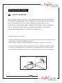
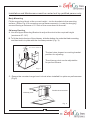
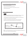
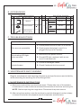
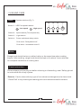
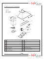
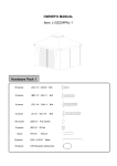
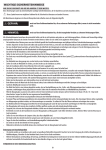
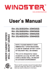
WALL HOOD
www.windsterhood.com
OPERATION
MANUAL
RA-1430C / RA-1490C
Please read and save this guide through before using your range hood
Store the guide away in a safe place so that you will know where it is
when you want to refer to it
Table of contents
A. Important safety Instructions
---------------------------- P.1
B. Safety notes ------------------------------------------------------ P.3
C. Tools and materials required ---------------------------------- P.6
D. L E D l i g h t r e p l a c e m e n t
E. Accessories
- - - - - - - - - - - - - - - - - - - - - - - - - - - - - - - P.6
------------------------------------------------- P.7
F. Troubleshooting -------------------------------------------------- P.7
G. Maintenance and cleaning------------------------------------------ P.7
H. M a i n t e n a n c e I n s t r u c t i o n
- - - - - - - - - - - - - - - - - - - - - - - - - - - - - - P.7
I.
Use and care ------------------------------------------------ P.8
J
Parts layout diagram -------------------------------------------- P.9
K. Circuit diagram ----------------------------------------------- P.10
L. Specifications -------------------------------------------------------- P.11
M. D i a g r a m s - - - - - - - - - - - - - - - - - - - - - - - - - - - - - - - - - - - - - - - - - - - - - - - - P.11
WARNING
Due to sharp edge, please wear " Safety Workman Gloves"
for installation, cleaning, light bulb changing and
dismantling to reduce the risk of any bodily injuries.
Safety Workman Gloves
A. IMPORTANT SAFETY INSTRUCTIONS
Read and Save These Instructions
1. Make sure the power is off before installing, wiring or maintenance.
2. Please keep the range hood clean.
3. To get the best performance, the vertical clearance between the cook- top
and the range hood should range from 28” to 32”. (Fig.1)
28”-32”
Fig.1 : Optimum range hood height
Ducting method
A. This range hood must be flued to external air space either through the roof
(fig.2 ) or through the wall (fig.3)
Fig. 2
Fig. 3
Ducting through the wall
Ducting through the roof
B. Obstruction of exhaust will cause
a. Uneven fan speed.
b. Could cause possible vibration.
CAUTION - To reduce the risk of fire and to properly exhaust air, be sure to duct
air outside. Do not vent exhaust air into spaces within walls, ceilings, attics,
crawl spaces or garages.
WARNING - To reduce the risk of fire or electric shock, do not use this fan with
any solid- state speed control device.
1
WARNING - To reduce the risk of fire, electric shock, or injury,
observe the following:
A. Use this unit only in the manner intended by the manufacturer. If you have
questions, contact the manufacturer.
B. Before servicing or cleaning the unit, switch the power for service panel and
lock panel, to prevent power from being switched on accidentally. When the
service is disconnecting, it cannot be locked, fasten a prominent warning
device, such as a tag, to the service panel.
C. Installation work and electrical wiring must be done by a qualified person(s) in
accordance with all applicable and standard codes, including fire-rated
construction.
D. Sufficient air is needed for proper combustion and exhausting of gases
through the flue(chimney) of fuel burning equipment to prevent back drafting.
Follow the heating equipment manufacturer's guideline and safety standards
such as those published by the National Fire Protection Association (NFPA),
the American Society for Heating, Refrigeration and Air Conditioning
Engineers(ASHRAE),and the local code authorities.
E. When cutting or drilling into wall or ceiling, do not damage electrical wiring
and other hidden utilities.
F. Ducted fans must always be vented to the outdoors.
CAUTION - For general ventilating use only. Do not use to exhaust hazardous
or explosive materials and vapours.
WARNING - To reduce the risk of a range top grease fire:
A. Clean ventilating fans frequently. Grease should not be allowed to accumulate
on fan or filters.
B. Always turn hood on when cooking at high heat or when cooking flaming foods.
C. Never leave surface units unattended at high settings.
Boilovers cause smoke and greasy spillovers, that may ignite and spread
if hood is used. Heat oils slowly on low or medium settings.
D. Don't leave your range unattended when cooking.
E. Use proper pan size. Always use cookware appropriate for the size of the
surface element.
2
WARNING- To reduce the risk of injury in the event of a range top grease fire,
observe the following:
A. SMOTHER FLAMES with a close- fitting lid, cookie sheet, or metal tray,
then turn off the burner. Be careful to prevent burns. If the flames do not
go out immediately, EVACUATE AND CALL THE FIRE DEPARTMENT.
B. NEVER PICK UP A FLAMING PAN - You may be burned.
C. DO NOT USE WATER including wet dishcloths or towels- a violent steam
explosion will result.
D. USE AN EXTINGUISHER ONLY IF:
1. You know you have a CLASS ABC extinguisher, and you already know
how to operate it.
2. The fire is small and contained in the area where it started.
3. The fire department is being called.
4. You can fight the fire with your back against the exit.
WARNING - To reduce the risk of fire, use only metal duct work.
B. SAFETY NOTES
1. All electrical work must be done in accordance with local and/or national
electrical code as applicable for safety. This product must be grounded, if you
are unfamiliar with methods of installing electrical wiring, secure the services
of a qualified electrician.
2. Turn off power at service entrance before installing, wiring, or servicing this
product. (120 volt for range hood. 220 volt for electric range if any)
3. Turn off power to avoid risk of fire, electric shock, or injury for cleaning or
maintenance such as lubrication.
4. Fireplaces, gas furnaces, water heaters, require proper flow of combustion
air and exhaust. Make sure this flow is not altered when using any exhaust fan.
5. Please read specification label on product for further information and
requirements.
6. Please wear "Safety Gloves" for installation, cleaning, light bulb changing and
dismantling to reduce the risk of any injuries.
NOTE : Exhaust air should not be discharged into any chimney or flue, which may carry
combustible products from other sources. In addition, exhaust air should not be
discharged into a wall cavity or into the roof space.
3
Wiring to Power Supply
SAFETY WARNING
RISK OF ELECTRICAL SHOCK. THIS RANGE HOOD MUST BE PROPERLY
GROUNDED. MAKE SURE THIS IS DONE BY SPECIALIZED ELECTRICIAN
IN ACCORDANCE WITH ALL APPLICABLE NATIONAL AND LOCAL
ELECTRICAL CODES. BEFORE CONNECTING WIRES, SWITCH POWER
OFF AT SERVICE PANEL AND LOCK SERVICE PANEL TO PREVENT
POWER FROM BEING SWITCHED ON ACCIDENTALLY.
Connect the electrical wires.
- Connect three wires (black, white and green) to house wires and cap with wire
connectors. Connect according to color :
black to black, white to white, and green to green as shown on Figure A.
- If necessary to hide the electrical wire connections, push wires back into the
wiring box. Access the wire connections underneath the hood. Make sure
wires do not slip between motor or any moving parts to prevent any damage.
Figure.A
Wire Connector
4
Installation and Maintenance must be carried out by qualified person only
Body Mounting
Fit the range hood body at the correct height , via the brackets to the mounting
surface. (Refer Fig.4 for mounting screw measurements). Locate the hanging
screw allowing a distance of 0.2 inch of the screw head to the wall.
Chimney Ducting
A. Use the Upper Mounting Bracket to adjust the duct to the required height
(maximum 27-1/6”)
B. To fit the duct to the top of the chimney, slide the bottom lip under the black mounting
and then lock in to place with the 4 screws provided. (Fig. 4)
7-
2/5
4/5
"
1-17/25 "
7-
"
The two holes depend on cowling bracket
position for adjusting.
Adjust it
flexibly to
fit the cabinet.
12-1/4 "
The chimney duct can be adjustable
for perfect fitment.
Fig. 4
C. Ensure the mounted range hood is level when installed for optimum performance.
(Fig.5)
Flexible hose included
Chimney duct
Fig. 5
5
C. TOOLS AND MATERIALS REQUIRED
◆ One common screwdriver.
◆ Plier (for opening electrical knockout).
◆ Electrical wire and supplies to comply with local cords.
◆ Electrical power drill.
D. REPLACEMENT LED LIGHT
Note:
Before replacing LED light ensure the unit is switched off, when you want to
change the LED light, please always wear working gloves. (Fig.6)
1. Using suitable tool (small slotted screw driver) gently pry off the LED light set.
2. Taking off the wire connecter with LED light set.
3. Replace a new LED light set and reconnect the wire to the connector.
4. Before push back the original LED light position, test the LED light.
LED driver:
Model: HP1500-36
input: 100~240vdc
output: 3.6vdc=1500maH
LED light: 1W
Model: HP-15A
Fig. 6
NOTE : For LED light replacement, you may not find the appropriate LED lights from
market, please contact with distributor(s)/dealer(s).
6
E. ACCESSORIES
Spare Parts Contents
Item
Part
Spare Parts Contents
Description
Spec. Q'ty Item
Manual
1
Part
Description
Spec. Q'ty
OPERATION
RA-1430C
Please read and save this guide through before using your range hood
Store the guide away in a safe place so that you will know where it is
when you want to refer to it
2
Round Collar
6" 7" 1
3
Duct CoverMounting Bracket
1
4
Screws Package
MANUAL
1
Screws
Ø4x32 6
Screws
Ø4x8
Plastic Screws 1/4"
8
6
F. TROUBLESHOOTINGS
Symptom
Correction
A. Check power source to see if it is normal.
Fan are not operatable.
Illuminating LED light
does not work
B. Check power inlet plug to see if it is
plugged firmly into it's socket.
A. Disconnect the power source.
B. Check LED light, replace it with a new
one if it is burned out.
A. Check for damaged vanes.
Hood vibrates.
B. Check if exhaust duct is secured.
G. MAINTENANCE AND CLEANING
Regular maintenance and cleaning will ensure good performance and reliability,
while extending the working-life of the Range hood.
H. MAINTENANCE INSTRUCTION
A. Maintenance should be important than repair. Please take care of the needed
maintenance in order to secure and extend the excellent functions and using life.
NOTE : Before repairing the range hood. Disconnect the power source.
B. After using the machine, wipe the machine by neutral detergent in order to keep
it clean and maintain the appearance with brightness and sanitation.
7
I. USE AND CARE
Note:
Operate switches (Fig.7)
④
Switch 1 : LED Fan speed indicator.
3
- Low speed
1
- High speed
③
②
①
8
Switch 2 : Speed switch (Three speed fan)
Fig.7
Switch 3 : Light switch
Switch 4 : Power switch and delay switch.
Push once : Delayed shut off.
Push twice : Immediate shut off.
Note:
Range hood should be turn on either before or the same time when cooking
begins. After cooking, range hood should be kept on for about 3 more minutes
for complete ventilation of cooking odor.
Care Instruction:
Please always pull the plug out before cleaning or dismantling, wear 'Safety gloves'
to reduce the risk of any injuries.
Exterior: Can be clean with any type of non-abrasive detergent and a clean cloth.
"Green Pad" or any metal type cleaning pad is not recommended for exterior.
8
J. PARTS LAYOUT DIAGRAM
4
Model:
RA-14 3 0C
RA-1490C
6
5
8
1
7
2
10
9
11
15
13
3
12
14
1.
Duct cover-Mounting bracket
2.
Duct cover
10. Capacitor support
3.
Plastic plate
11. LED driver
4.
Hood-Mounting bracket
12. Capacitor
5.
Rubber stand
13. Squirrel cage
6.
Hood casing
14. Aluminum filter
7.
LED Light
15. 6”/7” round collar
8.
Control board
16.
9.
9
Processor board
K. CIRCUIT DIAGRAM
Fig.8
Details the internal electrical circuit of this range hood unit.
Any faults with this unit should only be attended to by a
qualified technician.
White
Yellow
Orange
Red
Brown
Black
Yellow
Capacitor
Brown
White
Blue
Gray
Red
Motor
Yellow
Brown
White
Blue
Gray
Red
Motor
Brown
Black
LED driver
Black
LED light
Red
Black
Power
White
Ground
Fig.8 RA-14 Series Electrical Schematic Diagram
10
L. SPECIFICATIONS
RA-1 430 C /RA-1490C
Specifications
Body Dimension (WxDxH)
(W)29-3/4” 35- 3 /4" x ( D ) 24 - 1 / 8 " x ( H )12- 3 / 16 "
Low- 630 ± 50 R.P.M. /High- 1670 ± 50 R.P.M.
Revolutions
Consumption - Motor
1 42 W
Consumption - Lamp
1 W * 2 / 3.6 Vdc / 1500 maH
Rotation
Squirrel Cage
Diameter Exhausting Duct
6" / 7" Round Outlets
120V / 60 Hz
Voltage
Appearance Treatment
Brushed Stainless Steel
* Specifications subject to change without prior notice.
M. DIAGRAMS
MODEL : RA-1430C / RA-1490C
7-7
/8”
24-1/8”
/8”
18”
-5
10
-1/
8”
4”
-3/ /4”
9
2 -3
35
11
29-3/4”
24-1/8”
24
18”
1-3/4”
38-3/8”
27-5/8”
12-3/16”
35-3/4”
Limited Warranty
Windster Hoods Inc. warrants this product against defects in material or
wo rkmanship as fol lows:
1) Labor: For a period o f one (1 ) year from the date o f purchase, if th is p roduct
is determined to be defective, Windster wi ll repair or replace the product, at i ts
option, at no charge. After the warranty period, you must pay for all labor
charges. During the “ labor” war ranty period there wil l be no charge for labo r.
2) Parts: In addition, Windster will supply, at no charge, new or rebuilt
replacements in exchange for defective parts for a period of two (2) years.
After the warran ty per iod, you must pay for al l parts costs. Du ring the “parts”
warranty period, there will be no charge for parts
You must carry-in o r mai l-in your product du ring the warran ty period. Th is war ranty
only applies to products purchased and serviced in the United States or Canada.
What Is Not Covered By These Warranties:
1) Conditions and damages resulting from any of the following:
?
Improper installation, delivery, or maintenance.
?
Any repair, modification, alteration or adjustment not authorized by the
manufacturer or an authorized service dealers.
?
Misuse, abuse, accidents, or unreasonable use.
?
Incorrect electric current, voltage or supply.
?
Improper setting of any control.
?
Improper chemical cleaning.
2) Light Bulbs
3) Products purchased for commercial or industrial use (such as in a hotel, office,
restaurant, or other business)
4) Damage due to earthquake, flood, storm, etc.
Defective Products:
All products will be inspected, tested, and carefully packed by the manufacturer
before shipping to customers. Products that are damaged during transit can only be
exchanged for the same product, under the condition that the customer must get a
RMA (Return Merchandise Authorization) from Windster. When products are
received defective, you must notify us within the 3 business days of receiving the
package. Replacement products are only shipped when the RMA is issued. NO
EXCEPTIONS.
Return Policy
Windster offers only the best and highest quality products. If you are not satisfied
with your purchase, please contact us within 3 business days of product arrival to
obtain a Return Merchandise Authorization (RMA). Returns sent without a RMA will
not be accepted. There will be a 25% re-stocking fee for every returned items.
Shipping fee will also be deducted from the original purchase price. When returning a
package, please include a copy of your purchase receipt. Use the original shipping
box and packing materials and completely remove or cover the original shipping label.
Make sure that products are in brand new condition, uninstalled, un-drilled, and
contain everything that came with the package as when you first received it. If any
parts or manuals are missing, we have the right not to accept the return.
We suggest that you use a traceable and reputable carrier of your choice to ship your
return. Your credit or refund will be processed within 10-14 business days from the
date we receive your return.
FAX:626-350-1254