1
The Electric Helicopter Beginner's
Guide v17
Toshiyasu Morita
The Electric Helicopter Beginner's Guide v17
Toshiyasu Morita
Mark Pearson
Copyright © 2000-2006 Toshiyasu Morita
Copyright © 2005-2006 Mark Pearson
Table of Contents
Preface ..................................................................................................................xiii
1. Things You Should Know ......................................................................................1
1.1. Helicopters require a SIGNIFICANT TIME COMMITMENT ............................1
1.2. Repairs are expensive ................................................................................1
1.3. Hovering is difficult to learn .........................................................................1
1.4. Airplane experience may not help ................................................................1
2. Types of R/C Helicopters .......................................................................................2
2.1. Single rotor helicopters with fewer than four channels ...................................2
2.2. Coaxial helicopters with two to four channels ...............................................2
2.3. Multirotor helicopters with four channels ......................................................2
2.4. Four to six channel single rotor ....................................................................2
2.5. Summary of skills .......................................................................................2
3. First Helicopter Selection Guide .............................................................................4
3.1. Things to consider when selecting your first helicopter ..................................4
3.1.1. Recommended first heli choices .......................................................5
3.1.2. Recommended second heli choices ..................................................5
3.2. Clones .......................................................................................................5
3.2.1. Design problems .............................................................................6
3.2.2. Cheap plastic used for critical parts ..................................................6
3.2.3. Low quality electronics .....................................................................6
3.2.4. Nonstandard electronics ..................................................................7
3.2.5. Sloppy tolerances on molded and/or CNC milled parts .......................7
3.3. Classification of helis used in this guide .......................................................7
3.4. Overview of selected machines ...................................................................7
3.4.1. Lite Machines Corona ......................................................................8
3.4.2. Ikarus Fixed Pitch Piccolos (Fun or ECO) ..........................................8
3.4.3. Ikarus Collective Pitch Piccolos (CP upgrade/Pro) .............................8
3.4.4. Ikarus ECO Lite ...............................................................................9
3.4.5. Ikarus ECO 8 ..................................................................................9
3.4.6. Ikarus ECO 16 ................................................................................9
3.4.7. Ikarus Viper 70/MS Composit Stinger 3 ........................................... 10
3.4.8. Ikarus Viper 90/MS Composit Stinger 6 ........................................... 10
3.4.9. Feda Skylark/Century Hummingbird/GWS Dragonfly ....................... 10
3.4.10. JR Voyager E .............................................................................. 10
3.4.11. Kyosho Concept EP - discontinued? ............................................. 11
3.4.12. Mikado Logo 10 ........................................................................... 11
3.4.13. Mikado Logo 20 ........................................................................... 11
3.4.14. MS Composit Hornet FP .............................................................. 11
3.4.15. MS Composit Hornet CP .............................................................. 12
3.4.16. MS Composit Hornet II ................................................................. 12
3.4.17. Maxir SE ..................................................................................... 12
3.4.18. Robbe Spirit L-8/Eolo R22 ............................................................ 13
3.4.19. Quick Quick EP 10 ...................................................................... 13
3.4.20. Quick Quick EP 16 ...................................................................... 13
3.4.21. Zoom 400/Shogun 400/Zap 400 ................................................... 13
3.4.22. Align T-Rex 450X ........................................................................ 14
3.4.23. Align T-Rex 450XL HDE/CDE ....................................................... 14
3.4.24. ARK X-400 .................................................................................. 14
3.4.25. Hirobo XRB SR (Sky Robo) .......................................................... 15
3.5. Summary of helicopter sizes ..................................................................... 15
4. Recommended Configurations ............................................................................. 17
iv
The Electric Helicopter Beginner's Guide
v17
4.1. Beginner configurations ............................................................................ 17
4.1.1. Corona - brushed configuration ...................................................... 17
4.1.2. Corona - brushless configuration .................................................... 17
4.1.3. FP Piccolo - brushed + Piccoboard ................................................. 17
4.1.4. FP Piccolo - brushed - separates .................................................... 18
4.1.5. FP Piccolo - brushless - separates .................................................. 18
4.1.6. GWS Dragonfly - brushed - separates ............................................. 18
4.2. Intermediate configurations ....................................................................... 18
4.2.1. CP Piccolo or Pro - brushless - separates ....................................... 18
4.2.2. T-Rex 450XL ................................................................................. 19
4.2.3. Zoom 400 ..................................................................................... 19
4.2.4. Logo 10 - brushless ....................................................................... 19
4.2.5. ECO 8 - brushed ........................................................................... 20
4.2.6. ECO 8 - brushless ......................................................................... 20
5. Brushless Motor Upgrade Paths ........................................................................... 21
5.1. Corona upgrade paths .............................................................................. 21
5.1.1. Corona motors usable in an ECO 8 ................................................ 21
5.1.2. Corona motors usable in a Eolo ...................................................... 22
5.1.3. Corona motor usable in a Voyager E .............................................. 22
5.2. Piccolo upgrade paths .............................................................................. 22
6. Helicopter Parts Selection .................................................................................... 24
6.1. Control system ......................................................................................... 24
6.1.1. Receiver ....................................................................................... 24
6.1.2. Antenna ........................................................................................ 24
6.1.3. Gyros ........................................................................................... 24
6.1.4. FMA Copilot .................................................................................. 28
6.1.5. Revo mixing .................................................................................. 28
6.2. Servos ..................................................................................................... 28
6.2.1. Swashplate (cyclic) servos ............................................................. 28
6.2.2. Tail (rudder) servo ......................................................................... 29
6.3. Batteries and related items ....................................................................... 30
6.3.1. Batteries ....................................................................................... 30
6.3.2. Battery connectors ......................................................................... 32
6.3.3. BEC (battery eliminator circuit) ....................................................... 33
6.3.4. Wire ............................................................................................. 35
6.3.5. LiPo battery monitor ...................................................................... 36
6.3.6. Battery mounting strap ................................................................... 36
6.4. Motors and related items .......................................................................... 36
6.4.1. Motor ............................................................................................ 36
6.4.2. Pinion ........................................................................................... 44
6.4.3. Motor connectors ........................................................................... 44
6.4.4. Main motor ESC ............................................................................ 44
6.4.5. Tail motor ESC .............................................................................. 47
6.5. Other ....................................................................................................... 48
6.5.1. Modifications ................................................................................. 48
7. Support Equipment ............................................................................................. 50
7.1. Hand tools ............................................................................................... 50
7.1.1. Screw/hex/nut drivers .................................................................... 50
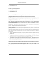
7.1.2. Ball link pliers ................................................................................ 50
7.1.3. Submini needle nose pliers ............................................................ 50
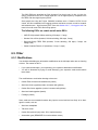
7.2. Helicopter tools ........................................................................................ 51
7.2.1. Pitch gauge ................................................................................... 51
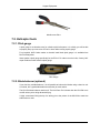
7.2.2. Blade balancer (optional) ............................................................... 51
7.2.3. Paddle pitch gauge (optional) ......................................................... 52
7.2.4. Prop balancer (optional) ................................................................. 52
7.2.5. Tachometer ................................................................................... 52
7.3. Adhesives ................................................................................................ 53
v
The Electric Helicopter Beginner's Guide
v17
7.3.1. CA Glue ........................................................................................ 53
7.3.2. CA accelerator .............................................................................. 53
7.3.3. CA debonder ................................................................................. 54
7.3.4. Epoxy ........................................................................................... 54
7.4. Charging equipment ................................................................................. 54
7.4.1. Battery chargers ............................................................................ 54
7.4.2. Battery charging containers ............................................................ 56
7.4.3. Power supplies .............................................................................. 56
7.4.4. Field battery (optional) ................................................................... 56
7.4.5. Field battery charger (optional) ....................................................... 58
7.4.6. Portable generator (optional) .......................................................... 58
7.5. Electronic instruments .............................................................................. 58
7.5.1. Digital voltmeter ............................................................................ 58
7.5.2. Wattmeter ..................................................................................... 59
8. Simulators .......................................................................................................... 60
8.1. FMS ........................................................................................................ 60
8.2. Piccofly with Game Commander ............................................................... 61
8.3. Easyfly .................................................................................................... 62
8.4. Aerofly Professional ................................................................................. 62
8.5. Aerofly Professional Deluxe ...................................................................... 63
8.6. Realflight G2 w/USB Interlink .................................................................... 64
8.7. Realflight G3 w/USB Interlink .................................................................... 65
8.8. Reflex XTR simulator w/USB interface ....................................................... 66
8.9. ClearView ................................................................................................ 68
8.10. PreFlight ................................................................................................ 68
8.11. PhoenixRC ............................................................................................ 69
8.12. Helicopter simulator for the Mac .............................................................. 70
8.13. Summary ............................................................................................... 70
8.14. Simulator practice ................................................................................... 71
9. Transmitters ....................................................................................................... 72
9.1. Suitable helicopter transmitters ................................................................. 72
9.2. Special transmitter notes .......................................................................... 74
9.2.1. Hitec Eclipse 7 with 90 CCPM ........................................................ 74
9.2.2. Hitec Eclipse 7 and yaw rate gyros ................................................. 75
9.2.3. Hitec Eclipse 7 bug ........................................................................ 75
9.2.4. Hitec Optic 6 problems ................................................................... 75
9.2.5. Futaba 7C bug .............................................................................. 75
9.2.6. JR 10X Airplane ............................................................................ 75
9.3. Transmitter tray ........................................................................................ 75
9.4. Transmitter hand position ......................................................................... 75
9.5. Transmitter manuals ................................................................................. 76
10. Helicopter Construction ..................................................................................... 77
10.1. General tips for all helicopters ................................................................. 77
10.1.1. Building ....................................................................................... 77
10.1.2. Threadlock .................................................................................. 77
10.1.3. Gear lubrication ........................................................................... 77
10.1.4. Frame assembly .......................................................................... 77
10.1.5. Stripped threads .......................................................................... 77
10.1.6. Breaking-in motors ...................................................................... 78
10.1.7. Carbon dust ................................................................................ 78
10.1.8. Capacitors ................................................................................... 78
10.1.9. Motor diode ................................................................................. 79
10.1.10. Ball links ................................................................................... 79
10.1.11. Motor shaft ................................................................................ 79
10.1.12. Brushless motor wires ................................................................ 79
10.1.13. Canopy painting ......................................................................... 80
10.1.14. Tail servo .................................................................................. 80
vi
The Electric Helicopter Beginner's Guide
v17
10.1.15. Mounting component ................................................................. 80
10.1.16. Ball in swashplate ...................................................................... 80
10.1.17. Removing CA glued joints .......................................................... 80
10.2. Specific tips for LMH Corona only ............................................................ 80
10.3. Specific tips for all Piccolo (Fun/ECO/CP upgrade/Pro) ............................. 81
10.4. Specific tips for fixed pitch Piccolo (ECO/Fun) only ................................... 82
10.5. Specific tips for collective pitch Piccolo (CP upgrade/Pro) only .................. 82
10.6. Specific tips for the MS Composit Hornet II .............................................. 82
10.7. Specific tips for Ikarus ECO 8/16 only ...................................................... 84
10.8. Specific tips for Logo 10 only ................................................................... 87
11. Helicopter Electronics Mounting/Wiring ............................................................... 89
11.1. Channel assignments ............................................................................. 89
11.1.1. Futaba/Hitec transmitters ............................................................. 89
11.1.2. JR transmitters ............................................................................ 89
11.1.3. Multiplex transmitters ................................................................... 90
11.1.4. Airtronics/Sanwa transmitters ....................................................... 90
11.2. Component placement ............................................................................ 91
11.3. Wire routing ........................................................................................... 92
11.4. Soldering technique ................................................................................ 92
12. Post-Construction/ARF Checklist ....................................................................... 95
13. Helicopter and Transmitter Setup ....................................................................... 96
13.1. Center of gravity setup ............................................................................ 96
13.1.1. Fore/aft center of gravity balancing ............................................... 96
13.2. Swashplate setup ................................................................................... 96
13.2.1. Swashplate type setup ................................................................. 96
13.2.2. Swashplate servo setup (CP heli only) .......................................... 97
13.2.3. Pitch curve setup (CP heli only) .................................................... 98
13.2.4. Cyclic setup (CP heli only) ............................................................ 99
13.2.5. Cyclic setup (FP heli only) .......................................................... 101
13.2.6. Transmitter exponential setup for cyclic ....................................... 102
13.3. Main rotor setup - part 1 ........................................................................ 102
13.3.1. Main rotor blade balancing using the KSJ-528 blade balancer ...... 102
13.3.2. Blade grip tension adjustment ..................................................... 103
13.3.3. Flybar paddle setup ................................................................... 104
13.4. Main motor setup ................................................................................. 104
13.4.1. Transmitter throttle reverse setup ............................................... 104
13.4.2. ESC programming ..................................................................... 104
13.4.3. Transmitter throttle setup ........................................................... 106
13.4.4. Transmitter throttle hold setup .................................................... 107
13.4.5. Transmitter throttle curve setup (FP heli only) .............................. 107
13.4.6. Transmitter throttle curve setup (CP heli only) ............................. 107
13.5. Tail rotor setup ..................................................................................... 109
13.5.1. Tail belt tension setup ................................................................ 109
13.5.2. Tail rotor pitch servo direction setup ............................................ 109
13.5.3. Tail rotor pitch servo centering .................................................... 110
13.5.4. Gyro setup - variable pitch tail rotor ............................................. 110
13.5.5. Gyro setup - fixed pitch tail rotor ................................................. 114
13.5.6. Transmitter tail setup - both fixed and variable pitch ..................... 116
13.6. Main rotor setup - part 2 ........................................................................ 116
13.6.1. Blade tracking - CP helicopters ................................................... 116
13.6.2. Blade tracking - FP helicopters ................................................... 117
14. R/C Heli Rules and Tips .................................................................................. 119
14.1. The proper way to carry a heli ............................................................... 119
14.2. Avoid pointing the transmitter antenna at the helicopter .......................... 119
14.3. The blades are traveling at high velocity! ................................................ 119
14.4. Always disconnect the battery when working on the helicopter ................ 120
14.5. Liability insurance ................................................................................. 120
vii
The Electric Helicopter Beginner's Guide
v17
15. Learning to Fly an R/C Helicopter ..................................................................... 121
15.1. The skills required ................................................................................ 121
15.2. Making the learning process easier ........................................................ 121
15.2.1. Hover no higher than eye level ................................................... 121
15.2.2. Paint your canopy a bright color or leave it white ......................... 121
15.2.3. Use white blades ....................................................................... 122
15.2.4. Use a heading hold gyro. ........................................................... 122
15.3. Minimize downtime; maximize practice time ........................................... 122
15.4. Divide the learning process into smaller, easier steps ............................. 122
16. Hovering Technique ........................................................................................ 124
17. Helicopter Power-On/Power-Off Procedure ....................................................... 125
17.1. Helicopter power-on procedure ............................................................. 125
17.2. Helicopter power-off procedure ............................................................. 126
17.3. Safety notes ......................................................................................... 126
18. Tail-In Hovering .............................................................................................. 127
18.1. Preparation .......................................................................................... 127
18.2. Tail-in hovering - Phase 1 ..................................................................... 127
18.3. Tail-in hovering - Phase 2 ..................................................................... 129
19. Side-In and Nose-In Hovering Orientations ....................................................... 131
19.1. To translate into a left side-in hover ....................................................... 131
19.2. To turn into a left side-in hover .............................................................. 131
20. Orientation Exercises ...................................................................................... 132
20.1. Introduction .......................................................................................... 132
20.2. Inverted T ............................................................................................ 132
20.3. 90 degree yaw ..................................................................................... 132
20.4. 180 degree yaw .................................................................................... 132
20.5. 45 degree nose-in orientations .............................................................. 133
21. Forward and Backward Flight ........................................................................... 134
21.1. Using idle-up mode ............................................................................... 134
21.2. Entering and exiting fast forward flight ................................................... 134
21.3. Banked forward turns ............................................................................ 134
21.4. Backwards flight ................................................................................... 135
21.5. Banked backwards turns ....................................................................... 135
22. Forwards and Backwards Exercises ................................................................. 137
22.1. Figure eights ........................................................................................ 137
22.2. Backwards remote half circles ............................................................... 137
22.3. Backwards remote full circles ................................................................ 137
22.4. Backwards tail-in figure-eight ................................................................ 137
22.5. Backwards nose-in figure-eight ............................................................. 137
23. Advanced Exercises ........................................................................................ 138
23.1. Single pirouette .................................................................................... 138
23.2. Multiple slow pirouettes ......................................................................... 138
23.3. Pirouetting remote circles ...................................................................... 138
23.4. Pirouetting figure eights ........................................................................ 138
24. Tweaking Helicopter Twitchiness ..................................................................... 140
24.1. Reduce the headspeed (CP helis only) .................................................. 140
24.2. Reduce the swashplate mixing .............................................................. 140
24.3. Increase exponential on aileron/elevator ................................................ 140
24.4. Add flybar weights ................................................................................ 140
25. Your First Major Crash .................................................................................... 141
26. Troubleshooting Common Problems ................................................................. 142
26.1. Vibration problems ............................................................................... 142
26.1.1. Excessive vibration (entire heli) .................................................. 142
26.1.2. Excessive vibration (tail only) ..................................................... 143
26.2. Tail control problems ............................................................................ 144
26.2.1. Tail keeps spinning and will not stop with HH gyro ....................... 144
26.2.2. Tail jerks around when spooling up with HH gyro ......................... 145
viii
The Electric Helicopter Beginner's Guide
v17
26.2.3. Tail wags (hunts) constantly with HH gyro ................................... 145
26.2.4. Tail swings 30-90 degrees abruptly then corrects itself ................. 146
26.2.5. Tail servo responds in one direction only ..................................... 147
26.2.6. Tail drifts as battery discharges .................................................. 147
26.2.7. Tail motor runs at low throttle ..................................................... 147
26.2.8. Tail servo creeps or does not recenter ........................................ 147
26.2.9. Tail servo travel is unequal ......................................................... 147
26.2.10. Tail motor has insufficient tail thrust .......................................... 147
26.2.11. Tail servo travel is not settable using Transmitter EPA with heading
hold gyro .............................................................................................. 147
26.2.12. Tail servo moves in the wrong direction with a heading hold gyro. Reversing the transmitter rudder channel has no effect. ............................... 147
26.2.13. Tail drifts during flight with heading hold gyro ............................. 148
26.3. Throttle/ESC problems .......................................................................... 148
26.3.1. Motor ESC will not arm, or motor runs at zero throttle .................. 148
26.3.2. Lost throttle control .................................................................... 148
26.3.3. Motor does not start turning till about 40% throttle ........................ 148
26.3.4. Motor surges with governor mode ............................................... 149
26.4. Swashplate problems ........................................................................... 149
26.4.1. Cyclic servos wiggle around when motor is running ..................... 149
26.4.2. eCCPM swashplate does not move correctly. .............................. 149
26.5. Glitching .............................................................................................. 149
26.6. Other problems .................................................................................... 150
26.6.1. Heli twitches randomly in roll/pitch/yaw ....................................... 150
26.6.2. Short flight times and/or not enough power .................................. 150
26.6.3. Slight tilt to the right (or left) ........................................................ 150
26.6.4. Unstable hover or wobbling ........................................................ 150
26.6.5. The blade tracking becomes worse at higher head speeds. .......... 150
27. Electric Helicopter and Parts Vendors ............................................................... 152
28. Frequently Asked Questions ............................................................................ 159
28.1. General questions ................................................................................ 159
28.1.1. How much does it cost? ............................................................. 159
28.1.2. How high will an R/C helicopter fly? ............................................ 159
28.1.3. How long will an R/C helicopter fly? ............................................ 159
28.1.4. How fast will a helicopter go? ..................................................... 160
28.1.5. What is the best helicopter? ....................................................... 160
28.1.6. Which helicopter should I buy? ................................................... 160
28.1.7. Should I buy an ARF helicopter? ................................................ 160
28.1.8. How does an R/C helicopter fly inverted? .................................... 160
28.1.9. Why does a CP helicopter handle wind better than an FP helicopter?
............................................................................................................. 160
28.2. Transmitters ......................................................................................... 160
28.2.1. What is the difference between an airplane transmitter and a helicopter
transmitter? .......................................................................................... 160
28.2.2. Can you give me your transmitter settings for helicopter X? .......... 161
28.2.3. Which receivers are compatible with my Walkera transmitter? ...... 161
28.2.4. Which transmitters are compatible with my Walkera receiver? ...... 161
28.2.5. Which transmitters are compatible with my E-flight Blade CP receiver?
............................................................................................................. 162
28.2.6. What is the difference between FM, PPM, and PCM? .................. 162
28.2.7. Can I use a JR/Graupner/Futaba/Robbe PCM reciever with my JR/
Graupner/Futaba/Robbe transmitter in PCM mode? ................................ 162
28.2.8. Can I use a crystal from manufacturer X in my receiver from manufacturer Y? ................................................................................................ 162
28.2.9. Can I use a single-conversion crystal in my dual-conversion receiver?
............................................................................................................. 162
28.2.10. Can I change the transmitter channel by changing the transmitter
ix
The Electric Helicopter Beginner's Guide
v17
crystal? ................................................................................................ 163
28.2.11. Why are channel 20 and/or channel 21 not recommended for use or
banned at my flying field? ...................................................................... 163
28.2.12. Can I use brand X servos with brand Y receivers? ..................... 163
28.2.13. When should I move from an FP helicopter to a CP helicopter? .. 163
28.3. Helicopter parts selection ...................................................................... 164
28.3.1. Do my servos need to be of identical type for eCCPM? ................ 164
28.3.2. How does the Castle Creations Phoenix ESC governor mode work? 164
28.4. Gyros .................................................................................................. 164
28.4.1. Can I hover without a gyro? ........................................................ 164
28.4.2. Is a heading hold gyro worth the cost? ........................................ 164
28.4.3. If I put a gyro on each swashplate servo, will the heli hover by itself?
............................................................................................................. 164
28.5. Helicopter setup ................................................................................... 164
28.5.1. How do I set the collective pitch of the main blades? .................... 164
29. Helicopter Myths ............................................................................................. 165
29.1. Expo is bad because it slows cyclic response ......................................... 165
29.2. Heading hold gyros are bad .................................................................. 165
29.3. Shorter flybar increases cyclic response ................................................ 165
29.4. Rate gyros do not need revo mixing ....................................................... 165
30. Technical Appendix ......................................................................................... 166
30.1. How helicopters work ............................................................................ 166
30.1.1. From the user to the transmitter .................................................. 166
30.1.2. Inside the transmitter ................................................................. 167
30.1.3. From the transmitter to the lower swashplate ............................... 167
30.1.4. From the upper swashplate to the rotor head ............................... 169
30.1.5. The rotorhead ............................................................................ 171
30.1.6. Basic helicopter aerodynamics ................................................... 171
30.1.7. How gyros work ......................................................................... 172
30.1.8. GY-series gyro technical info ...................................................... 175
30.1.9. Yaw-rate gyro technical info ....................................................... 178
30.1.10. How ESCs work ....................................................................... 179
30.1.11. How batteries work .................................................................. 181
30.1.12. How motors work ..................................................................... 181
30.2. Motor selection guide ............................................................................ 186
30.2.1. Electrical characteristics ............................................................. 186
30.2.2. Physical characteristics .............................................................. 187
30.2.3. Other characteristics .................................................................. 189
30.3. Motor selection table ............................................................................ 190
30.4. Pinion selection guide ........................................................................... 199
30.4.1. Pitch to module conversion ........................................................ 199
30.4.2. Common pitch equivalents ......................................................... 199
30.4.3. Shaft sizes ................................................................................ 200
30.4.4. Pinion notes .............................................................................. 200
30.5. Pinion selection tables .......................................................................... 201
30.6. Servo selection guide ........................................................................... 204
30.6.1. Electrical characteristics ............................................................. 204
30.6.2. Physical characteristics .............................................................. 205
30.7. Electronics modification guide ............................................................... 206
30.7.1. Adding a brushless motor to a brushed 3-in-1 controller ............... 206
30.7.2. Adding a heading hold gyro to a brushed 3-in-1 controller ............ 207
30.7.3. Brushed tail motor to brushless conversion ................................. 207
30.8. Battery info .......................................................................................... 207
30.8.1. Battery terminology primer ......................................................... 207
30.8.2. Battery pack series/parallel rating ............................................... 207
30.8.3. Battery capacity rating ............................................................... 208
30.8.4. Internal resistance/discharge rate ............................................... 208
x
The Electric Helicopter Beginner's Guide
v17
30.9. Battery care and maintenance ............................................................... 208
30.9.1. Nickel-cadmium (NiCad) batteries ............................................... 208
30.9.2. Nickel-metal-hydride (NiMH) batteries ......................................... 209
30.9.3. Lithium-Polymer (LiPo) batteries ................................................. 209
30.9.4. NiCad/NiMH/LiPo Battery disposal .............................................. 209
30.9.5. Solderless power tube (SPT) battery packs ................................. 210
30.10. Maintenance and crash repair ............................................................. 210
30.10.1. Brushed motors w/carbon brushes ............................................ 210
30.10.2. Main rotor shaft bearings .......................................................... 210
30.10.3. Tail rotor shaft bearings ............................................................ 210
30.10.4. Tail belt tension ....................................................................... 210
30.10.5. Battery retaining o-rings ........................................................... 210
30.10.6. Main rotor blades ..................................................................... 211
30.10.7. Ball links ................................................................................. 211
30.10.8. Servo wear .............................................................................. 211
30.10.9. Ball bearings ........................................................................... 211
30.10.10. Corona specific maintenance .................................................. 211
30.10.11. Piccolo specific maintenance .................................................. 211
30.10.12. ECO 8/16 specific maintenance .............................................. 212
30.11. Useful equations ................................................................................. 212
30.11.1. Calculating headspeed ............................................................. 212
30.11.2. Estimating power consumption ................................................. 213
31. Glossary ......................................................................................................... 214
xi
List of Tables
2.1. Helicopter types .................................................................................................2
3.1. Helicopter size summary sorted by AUW .............................................................5
3.2. Helicopter size summary sorted by AUW ........................................................... 15
5.1. Piccolo Upgrade Motors .................................................................................... 22
6.1. Wire size recommended by current capacity ...................................................... 35
13.1. Swashplate type setup .................................................................................... 97
13.2. Recommended headspeeds .......................................................................... 108
28.1. Beginners setup cost breakdown ................................................................... 159
30.1. Mode 1 stick assignments ............................................................................. 166
30.2. Mode 2 stick assignments ............................................................................. 166
30.3. Mode 3 stick assignments ............................................................................. 166
30.4. Mode 4 stick assignments ............................................................................. 167
30.5. Heatsinks ..................................................................................................... 188
30.6. Motor quality ................................................................................................ 190
30.7. Motors sorted by weight ................................................................................ 190
30.8. Pinions 2mm bore 0.5 module ....................................................................... 201
30.9. Pinions 2.3mm bore 0.5 module .................................................................... 202
30.10. Pinions 3mm bore 0.5 module ..................................................................... 202
30.11. Pinions 3.17mm bore 0.5 module ................................................................ 202
30.12. Pinions 5mm bore 0.5 module ..................................................................... 203
30.13. Pinions 5mm bore 0.7 module ..................................................................... 203
30.14. Pinions 5mm bore 1.0 module ..................................................................... 204
xii
Preface
by Toshiyasu Morita (TMorita on the Ezone and Ikarus BBS) and Mark Pearson (MRP on the
Ezone and HeliSpot BBS)
Copyright (C) 2002-2006 Toshiyasu Morita. Portions copyright (C) 2005-2006 Mark Pearson.
All trademarks are the property of their respective owners. Text by Toshiyasu Morita & Mark
Pearson. All photographs and screen captures by Mark Pearson unless otherwise credited.
This work is licensed under the Creative Commons Attribution-NoDerivs-NonCommercial License. To view a copy of this license, visit creativecommons.org/licenses/by-nd-nc or send a
letter to: Creative Commons, 559 Nathan Abbott Way,Stanford,Ca 94305 USA
The latest version of the EHBG is available from ehbg.rchomepage.com.
Many thanks to all the people on the Ezone forums and the Ikarus BBS who have posted many
helpful messages - many of these tips were taken from these excellent discussion forums!
This was originally a "Heli FAQ" suggested by Fred Bronk, but it grew into much more than a
FAQ - so now it's called the Electric Helicopter Beginner's Guide.
This guide assumes some prior R/C experience, such as R/C planes or cars. Therefore, it
doesn't explain terms such as "servo" or the correct orientation for servo plugs, etc. If you need
these questions answered, I recommend asking in the "Beginner Training Area" on RC Groups
.
Be sure to check Chapter 31, Glossary if you encounter terms which you don't know, such as
swashplate, collective pitch, etc.
Note
Use this information at your own risk! I make no guarantees as to the validity of
any of this information! If in doubt, double-check!
xiii
Chapter 1. Things You Should Know
1.1. Helicopters require a SIGNIFICANT TIME COMMITMENT
R/C helicopters are not dynamically stable, and they require constant stick input. It's very similar to balancing a marble on a sheet of glass by radio control. In addition to this, the glass can
be rotated which then rotates all the directions.
Therefore, it takes a lot of time to develop a good sense of balance and orientation. You will
learn much faster if you can dedicate at least a half-hour a day to practicing on a flight simulator.
In addition, helicopters require significant amounts of time to build and isolate/fix various problems like vibration, tail wag, and other problems that will develop.
If you like building and tinkering with things for hours, and enjoy the challenge and satisfaction
of learning difficult skills, then this is a great hobby for you.
If you don't like building and tinkering with things for hours and are easily frustrated by learning
difficult skills, then you may want to consider another hobby.
1.2. Repairs are expensive
Helicopters crash, and they are somewhat expensive to fix
Some helicopters are more durable than others, and some are much cheaper to fix - these are
good trainers. But, you cannot expect to learn to fly without spending some money for repairs.
Be sure to allocate some money for repairs.
1.3. Hovering is difficult to learn
Eventually, something will "click" inside your head, and you will "get it". For some people, this
occurs all of a sudden and everything makes sense. For other people it seems to be a more
gradual process.
Basically, helicopters suck horribly. Then you get your first hover, and it's an incredible headrush, and you're psyched for a whole week, and you're hooked. :)
1.4. Airplane experience may not help
Many people find that R/C airplane experience does not necessarily help when learning to fly
R/C helicopters.
In particular, the normal airplane instinct to throttle down and pull back elevator when losing
orientation will result in a crash when applied to a helicopter.
Also, airplanes do not need much rudder when turning, which is very different from a helicopter. A helicopter requires much more tail management than an airplane.
1
Chapter 2. Types of R/C Helicopters
There are four basic types of R/C helicopters:
1.
Single rotor helicopters with fewer than four channels
2.
Coaxial helicopters with two to four channels
3.
Multirotor helicopters with four channels
4.
Single rotor helicopters with four or more channels
2.1. Single rotor helicopters with fewer than four channels
This category includes helicopters such as the Nikko Skywatcher.
You cannot learn to hover properly on this type of helicopter, because it lacks the fore/aft cyclic
control. Also, the forward flight skills you learn on this helicopter will not transfer over to other
types of helicopters because you will not learn proper tail control.
2.2. Coaxial helicopters with two to four channels
This category includes such helicopters as the Hirobo XRB, the E-flight Blade CX, the Bladerunner II and the GPL Wild Wheels.
This type of helicopter has electronic stabilization circuitry, so you will not develop proper hovering skills. They also do not perform banked turns, so you will not develop forward flight turning skills. You can develop orientation skill with this type of helicopter, though.
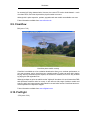
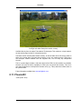
2.3. Multirotor helicopters with four channels
This category includes helicopters such as the X-UFO and Draganflyer.
This type of helicopter is inherently stable, so you will not develop proper hovering skills. They
also do not perform banked turns, so you will not develop forward flight turning skills. You can
develop orientation skill with this type of helicopter, though.
2.4. Four to six channel single rotor
This type of helicopter has all of the basic controls, so you can learn hovering, orientation, and
forward flight skills.
The information in the EHBG is mainly relevant to this category of R/C helicopters.
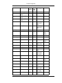
2.5. Summary of skills
Different types of R/C helicopters wil allow you to learn different skills.
Table 2.1. Helicopter types
2
Types of R/C Helicopters
Visual orientation
Hovering
skills
Forward flight
skills
Single rotor with <4 channels
no
no
no
Coaxial with 2-4 channels
yes
no
no
Multirotor with 4 channels
yes
no
no
Single rotor with >4 channels
yes
yes
yes
3
Chapter 3. First Helicopter Selection Guide
3.1. Things to consider when selecting your first helicopter
•
Durability
•
Price of replacement parts
•
Availability of replacement parts
•
Size
The reason for this is: when you are learning to hover, you will crash. This is a given. Everyone
crashes. When you crash, you do not want to spend a fortune repairing the helicopter, because everyone has limited funds. When you crash, you do not want to wait forever for replacement parts, because every day you spend waiting for a part is a day you are not flying the
helicopter, and learning something.
Size is very important, because larger helis are more stable and easier to hover. They have
more inertia, so they move slower and they give more warning of their intent. Micro helis are
more difficult to hover because they are very skittish and wander off in a new direction with
very little warning of their intent. Larger helis are not any easier to fly, though.
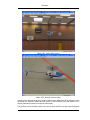
If you live in an area like Seattle where it rains almost continuously for nine months of each
year, I would recommend a fixed-pitch Piccolo. Otherwise the Lite Machines Corona is the best
electric trainer available today. The Corona is very stable and acts like a much larger helicopter, so it is nearly ideal for learning hovering.
To make a plane analogy, the Corona is basically the Slow Stick of R/C helicopters. It has a
simple fixed-pitch rotor design which is very durable, and usually receives very little damage (if
any) in most beginner crashes.
You may be tempted to buy an aerobatic 3D helicopter for your first helicopter. This is a bad
idea, because aerobatic helicopters are usually much less stable. They are usually designed
with a high center of gravity and very sensitive controls so they can roll and flip faster for aerobatic moves.
Think of this plane analogy: if your were an R/C airplane beginner, should you buy a hotliner
for your first plane?
Be sure to purchase your helicopter from a shop that carries a full line of replacement parts
and can ship replacement parts quickly. When you are learning to hover it's virtually guaranteed that you will crash a few times, and when you do you will want replacement parts ASAP.
Any R/C helicopter for which you cannot buy replacement parts is not properly repairable, and
is basically a paperweight.
Also, lithium-polymer batteries are fragile and easily damaged in helicopter crashes. For this
reason, we do not recommend using lipo batteries on your first helicopter. Some helicopter are
not flyable using NiCad and NiMH batteries, and require lipo batteries, and therefore these
helicopters are not recommended for beginners.
Also, GET A SIMULATOR. Even a free simulator such as FMS will save you at least 100 dollars or so in replacement parts when learning hovering.
The Walkera helicopters are not recommended for beginner helicopters because the electronics are of very poor quality. Various problems which have been reported include:
4
First Helicopter Selection Guide
•
Transmitters and receivers have very short range and/or interference problems
•
Servos jitter and/or have centering problems
These problems will make learning hovering much more difficult.
3.1.1. Recommended first heli choices
•
Corona (very durable, easier to hover, inexpensive)
•
Logo 10 (durable, easier to hover, expensive)
•
ECO Piccolo / Piccolo Fun (very durable, hard to hover, inexpensive)
•
Century Hummingbird, GWS Dragonfly, Skylark and exact clones (durable, hard to hover,
inexpensive)
•
Voyager E (durable, easier to hover, expensive)
•
Hirobo XRB SR (durable, simple to hover, expensive, limited )
3.1.2. Recommended second heli choices
These are not recommended for your first helicopter, but would be good for your second helicopter.
•
Hornet FP/CP (fragile)
•
ECO Lite/8/16 (somewhat fragile)
•
Logo 16/20 (expensive)
•
Joker / Joker CX (expensive)
•
Century Hummingbird Elite FP/CP (high headspeed)
•
Century Hummingbird v3 (fragile)
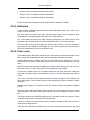
3.2. Clones
Some of the helicopters today are either nearly exact copies of other helicopters, or have
nearly exact copies of some major pieces.
Table 3.1. Helicopter size summary sorted by AUW
Original
Clone
Feda Dragonfly/GWS Dragonfly/Century Hummingbird V1/V2
Hornet II
Smartech Skylark, Smartech Aerohawk, Evoflight Sabre, Esky Honey
Bee Mark 2, Venom Night Ranger II,
Walkera Dragonfly #4
Eflight Blade CP (cloned head), E-sky
Honey Bee CP (cloned head), E-sky
Honey Bee King (cloned head), Venom
5
First Helicopter Selection Guide
Original
Clone
Night Ranger 3D (cloned head),
Walkera Dragonfly 22D and 22E
Zoom 400/Zap 400/Shogun v1
Revo CP, Walkera Dragonfly 35
Zoom 400/Zap 400/Shogun v2
Walkera Dragonfly 36
T-rex 450XL
Walkera Dragonfly 39
Quick Japan EP8
Quick Worldwide Little Quickie 8
Quick Japan 16
Quick Worldwide Sweet 16
Many of the Chinese clones are attractive to beginners due to their low cost, however, they often have many problems. The problems most often seen in Chinese clones are:
3.2.1. Design problems
Some Chinese clones are direct or nearly-direct clones of other helicopters, but with a few
changes (probably to avoid patent issues).
Sometimes these small changes cause serious problems, such as the Eflight Blade CP/Esky
Honey Bee CP problems with abrupt bouncing problems in flight. Search the RCgroups Micro
Helis forum for "sticky collective" or "yoyo" for more information.
3.2.2. Cheap plastic used for critical parts
The Chinese clones typically use cheap plastic for the main rotor hub, main blade grips,
frames and other critical parts. The better helicopters use glass-reinforced plastic (GRP) for
these parts which minimizes crash damage.
3.2.3. Low quality electronics
Many of the Chinese clones have problems with:
3.2.3.1. Transmitters and receivers
Transmitters and receivers which have limited range and/or severe interference problems
(Walkera helicopters)
•
www.rcgroups.com/forums/showthread.php?t=421883
•
www.rcgroups.com/forums/showthread.php?t=389062
•
www.rcgroups.com/forums/showthread.php?t=371046
•
www.rcgroups.com/forums/showthread.php?t=359992
•
www.rcgroups.com/forums/showthread.php?t=359402
3.2.3.2. Servos
Servos which jitter or have poor centering, or fail after the first few flights (Walkera helicopters)
•
www.rcgroups.com/forums/showthread.php?t=437059
•
www.rcgroups.com/forums/showthread.php?t=421680
6
First Helicopter Selection Guide
•
www.rcgroups.com/forums/showthread.php?t=412295
•
www.rcgroups.com/forums/showthread.php?t=384344
•
www.rcgroups.com/forums/showthread.php?t=381433
•
www.rcgroups.com/forums/showthread.php?t=393943
3.2.3.3. Low quality transmitter joysticks
The potentiometers in many low quality transmitters are not accurate and will cause the heli to
jump around.
•
www.rcgroups.com/forums/showthread.php?t=459902
3.2.4. Nonstandard electronics
The Walkera transmitters and receivers are not compatible with standard negative and positive
shift equipment from other manufacturer such as JR, Futaba, Hitec, Airtronics, etc.
3.2.5. Sloppy tolerances on molded and/or CNC milled parts
People have complained about Quick Heli kits (not to be confused with Quick Japan or Quick
UK) having manufacturing problems.
•
www.runryder.com/helicopter/t194374p1
•
www.runryder.com/helicopter/t154779p1
•
www.runryder.com/helicopter/t195107p1
Also seen on Walkera helicopters:
•
www.rcgroups.com/forums/showthread.php?t=401657
3.3. Classification of helis used in this guide
•
Living room flyer: These helis are flyable in small indoor areas and also outdoors when
completely calm. They are typically fixed pitch helis using wide blades which are efficient at
low headspeeds, and weigh up to about 350 grams.
•
Gym flyer: These helis are flyable in larger indoor areas, and also outdoors when relatively
calm. They are typically collective pitch helis up to about 600 grams.
•
Backyard flyer: These helis reqire a small outdoor field and are flyable in mild winds up to
about 8 km/h (5 mph). Not flyable indoors!
•
Large field flyer: These helis require a larger outdoor field and are flyable in winds up to
about 16 km/h (10 mph. Not flyable indoors!
3.4. Overview of selected machines
7
First Helicopter Selection Guide
3.4.1. Lite Machines Corona
•
A very good trainer
•
Moderately inexpensive (retail about $180-$199)
•
Very durable
•
Manufacturer is in the US. Parts availability is very good.
•
1250-1500 grams AUW, 610mm rotor diameter, 6-8 cells
•
large, moderate headspeed, easy to learn hovering - not indoors in small venues (gym ok)
•
Backyard flyer, maybe in gyms
3.4.2. Ikarus Fixed Pitch Piccolos (Fun or ECO)
•
Trainer, but harder to learn (probably 50% harder than Corona)
•
Inexpensive (Fun retail ~$90, ECO retail ~$140)
•
Fairly durable but landing gear is flimsy; requires reinforcement for beginners.
•
Manufacturer in Germany. Parts availability is good.
•
280 grams AUW, 500mm main rotor diameter, 6-8 cells
•
Small, low headspeed, hard to learn hovering, but can be flown indoors
•
Living room/Gym flyer
The main differences between an ECO Piccolo and a Fun Piccolo are:
•
The ECO Piccolo includes six ball bearings for the rotor head, the main shaft, and the tail
shaft. The Fun Piccolo includes bushings instead.
•
The ECO Piccolo has CF main and tail rotor shafts. The Fun Piccolo has steel main and tail
rotor shafts. The steel shafts run smoother than the CF shafts but they are somewhat heavier.
•
The ECO Piccolo includes tail motor connectors. The Fun Piccolo includes with no tail motor connectors, and the tail motor wires must be soldered directly to the Piccoboard or the
ESC wires.
•
The ECO Piccolo has a very lightweight tail boom. The Fun Piccolo has a slightly heavier
tail boom
3.4.3. Ikarus Collective Pitch Piccolos (CP upgrade/Pro)
•
Medium to advanced flyers
•
Inexpensive (CP upgrade ~$99, Pro retail ~$199)
•
Fairly durable except for balsa main rotor blades (68213) pitch arm base(68211) and landing gear.
8
First Helicopter Selection Guide
•
Manufacturer in Germany. Parts availability is good.
•
330 grams AUW,540mm rotor diameter, 8-9 AAA cells
•
Small, high headspeed. hard to learn hovering
•
Gym flyer
3.4.4. Ikarus ECO Lite
•
Only for experienced pilots - only does forward flight
•
Inexpensive (retail about $140)
•
Somewhat fragile, same weakness as ECO 8.
•
Manufacturer in Germany. Parts availability spotty,
•
1150 grams AUW, 760mm rotor diameter, 6-8 SubC cells
•
Doesn't hover. Forward flight only.
•
Backyard flyer.
3.4.5. Ikarus ECO 8
•
Duration flying/slope soaring/moderate aerobatics capable
•
Moderately inexpensive (retail about $180)
•
Somewhat fragile - stock (non-hardened) main rotor shaft, feathering shaft and tail rotor
shafts bend easily, frame and landing gear not very strong
•
Manufacturer in Germany. Parts availability spotty, up to 4 weeks wait time for some parts.
•
1300-1500 grams AUW, 1060mm rotor diameter, 6-12 SubC cells
•
Large, high headspeed, easy to learn hovering
•
Backyard flyer
3.4.6. Ikarus ECO 16
•
Moderate to serious aerobatics capable
•
Moderately inexpensive(retail about $250)
•
Somewhat fragile- a little more than ECO 8 because using the same parts for heavier helicopter
•
Manufacturer in Germany. Parts availability spotty, up to 4 weeks wait time for some parts.
•
2000 grams AUW, 1200mm rotor diameter, 12-20 SubC cells
•
Large,high headspeed, easy to learn hovering
•
Large field flyer
9
First Helicopter Selection Guide
3.4.7. Ikarus Viper 70/MS Composit Stinger 3
•
Moderate to serious aerobatics capable
•
Moderately inexpensive (retail ahout $250)
•
About average durability
•
Manufacturer in Germany
•
700-900 grams AUW, 750mm rotor diameter, 3-5s lipo
•
Small, high headspeed, difficult to learn hovering
•
Backyard flyer
3.4.8. Ikarus Viper 90/MS Composit Stinger 6
•
Moderate to serious aerobatics capable
•
Moderate (retail ahout $300)
•
About average durability
•
Manufacturer in Germany
•
1000-1200 grams AUW, 900mm rotor diameter, 3-5s lipo
•
Medium, high headspeed, hard to learn hovering
•
Backyard flyer
3.4.9. Feda Skylark/Century Hummingbird/GWS Dragonfly
•
Trainer, but harder to learn (probably 50% harder than Corona)
•
Inexpensive - $80 for bare heli kit
•
Fairly durable, but rotor blades are stiffer? than Piccolo and are more easily destroyed.
•
Manufacturer in Taiwan?. Parts availability is good.
•
280 grams AUW, 8 AAA cells
•
Small, low headspeed, hard to learn hovering, but can be flown indoors
•
Living room, Gym flyer
3.4.10. JR Voyager E
•
Trainer/light aerobatics capable
•
Expensive (retail about $400 incl. motor, cannot buy without motor)
•
About average durability
•
Manufacturer in Japan. Parts availability very good.
10
First Helicopter Selection Guide
•
1500 grams AUW, 965mm rotor diameter, 7 SubC cells
•
Large, high headspeed, easy to learn hovering
•
Backyard flyer
3.4.11. Kyosho Concept EP - discontinued?
•
Trainer/light aerobatics
•
Expensive (retail about $380 incl motor, cannot buy without motor)
•
About average durability
•
Manufacturer in Japan. Parts availability ?
•
1500 grams AUW , 912mm rotor diameter, 7 SubC cells
•
Large, high headspeed. Has weak power due to high disc loading. Flapping head version is
very prone to boom strikes.
•
Backyard flyer
3.4.12. Mikado Logo 10
•
Trainer/moderate aerobatics capable
•
Expensive (retail about $340)
•
About average durability
•
Manufacturer in Germany. Parts availability okay.
•
~2500 grams AUW, 1150mm rotor diameter, 10-14 SubC cells
•
Large, high headspeed, easy to learn hovering. Outdoors only
•
Large field flyer
3.4.13. Mikado Logo 20
•
Serious aerobatics capable
•
Expensive (retail about $470)
•
About average durability
•
Manufacturer in Germany. Parts availability okay.
•
>3000 grams AUW, 1340mm rotor diameter, 20-24 SubC cells
•
Large, high headspeed, easy to learn hovering. Outdoors only
•
Large field flyer
3.4.14. MS Composit Hornet FP
11
First Helicopter Selection Guide
•
Moderate aerobatics capable
•
Inexpensive (retail about $150)
•
Fragile
•
Manufacturer in Czech Republic. Parts availability okay.
•
280 grams AUW, 490mm rotor diameter, AAA 7-8 cells
•
Small, low headspeed, hard to learn hovering,- but can be flown indoors
•
Gym flyer
3.4.15. MS Composit Hornet CP
•
Moderate to serious aerobatics capable
•
Inexpensive (retail about $200)
•
Fairly
•
Manufacturer in Germany. Parts availability okay.
•
280 grams AUW, 490mm rotor diameter, 7-8 AAA cells
•
Small, high headspeed, hard to learn hovering,- but can be flown indoors
•
Gym flyer
3.4.16. MS Composit Hornet II
•
Moderate to serious aerobatics capable
•
Inexpensive (retail about $250)
•
Fragile, but more durable than Hornet FP/CP
•
Manufacturer in Germany. Parts availability okay.
•
330 grams AUW, 560mm rotor diameter, 7-8 AAA cells
•
Small, high headspeed, hard to learn hovering,- but can be flown indoors
•
Gym flyer
3.4.17. Maxir SE
•
Moderate to serious aerobatics capable
•
Inexpensive (retail about $240)
•
About average durability
•
Manufacturer in Czech Republic. Not many dealers.
•
350-420 grams AUW, 620mm rotor diameter, 3S LiPo
•
Small, high headspeed, hard to learn hovering
12
First Helicopter Selection Guide
•
Gym flyer
3.4.18. Robbe Spirit L-8/Eolo R22
•
Moderate aerobatics capable
•
Expensive (retail about $300)
•
About average durability
•
Manufacturer in Germany?, parts availability okay
•
1280g AUW, 810mm rotor diameter, 8 SubC cells
•
Large, high headspeed, easy to learn hovering, outdoors only
•
Backyard flyer
3.4.19. Quick Quick EP 10
•
Moderate aerobatics capable
•
Inexpensive (retail about $250)
•
About average durability
•
Manufacturer in USA. Parts availability good?
•
??? grams AUW, 880-950mm rotor diameter, 10-14 SubC cells
•
Large, high headspeed, easy to learn hovering, outdoors only
•
Backyard flyer
3.4.20. Quick Quick EP 16
•
Moderate to advanced aerobatics capable
•
Expensive (retail about $400)
•
About average durability.
•
Manufacturer in USA. Parts availability good?.
•
??? grams AUW, 1060-1080mm rotor diameter, 16-24 SubC cells
•
Large, high headspeed, easy to learn hovering, outdoors only.
•
Backyard flyer
3.4.21. Zoom 400/Shogun 400/Zap 400
•
Moderate to advanced aerobatics capable
•
Inexpensive (retail about $200)
13
First Helicopter Selection Guide
•
About average durability.
•
Manufacturer in Taiwan. Parts availability good.
•
500 grams AUW, 635mm rotor diameter, 3s1p lipos
•
Small, high headspeed, moderate to learn hovering
•
Gym flyer, Backyard flyer
3.4.22. Align T-Rex 450X
•
Moderate to advanced aerobatics capable
•
Inexpensive (retail about $160)
•
About average durability.
•
Manufacturer in Taiwan. Parts availability good.
•
650 grams AUW, 640mm rotor diameter, 3s1p lipos
•
Small , high headspeed, moderate to learn hovering
•
Gym flyer, Backyard flyer
3.4.23. Align T-Rex 450XL HDE/CDE
(Note: HDE version is mechanical mixing; CDE is eCCPM)
•
Moderate to advanced aerobatics capable
•
Inexpensive (retail about $200)
•
About average durability, low priced replacement parts
•
Manufacturer in Taiwan. Parts availability good
•
620-670 grams AUW, 640mm rotor diameter, 3s1p lipos
•
Small , high headspeed, moderate to learn hovering
•
Gym flyer, Backyard flyer
3.4.24. ARK X-400
•
Moderate to advanced aerobatics capable
•
Inexpensive (retail about $200)
•
About average durability.
•
Manufacturer in ?. Parts availability fair
•
580-620 grams AUW, 588mm rotor diameter, 3s1p lipos
•
Small , high headspeed, moderate to learn hovering
14
First Helicopter Selection Guide
•
Gym flyer, Backyard flyer
3.4.25. Hirobo XRB SR (Sky Robo)
•
A good trainer for beginners learning to hover
•
Expensive (~$300)
•
Fairly durable except for foam rotor blades. (Parts 0301001 and 0301002)
•
Manufacturer in Japan. Parts availability is good.
•
195 grams AUW,350 mm rotor diameter, 2s LiPo cells
•
Small, low headspeed. Perfect to learn hovering orientations. Not suitable to learn FFF.
•
Living room flyer
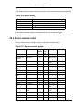
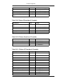
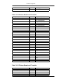
3.5. Summary of helicopter sizes
This table summarizes the main size parameters of the helicopters in the preceeding section.
AUW (All up weight) is in grams, Rotor Diameter is in mm and the Cell count indicates the
"standard" configuration assumed by the manufacturer. Many people are using LiPo packs instead of the original NiCd or NiMh packs, but for the purposes of this table, the original recommendation has been retained.
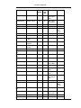
Table 3.2. Helicopter size summary sorted by AUW
Name
AUW
Rotor Dia.
Cells
Hirobo XRB SR (Sky Robo)
195
350
2S Lipo
Ikarus Piccolo FP (Fun)
280
500
6-8 AAA
Century Hummingbird FP
280
508
7-8 SubC
MS Composit Hornet FP
280
490
7-8 AAA
MS Composit Hornet CP
280
490
7-8 AAA
MS Composit Hornet II
330
560
7-8 AAA
Ikarus Piccolo CP
330
540
8-9 AAA
350-420
620
3S LiPo
Zoom 400/Shogun 400/Zap 400
500
635
3S Lipo
ARK X-400
580
588
3S Lipo
Align T-Rex 450X
650
640
3S Lipo
620-670
640
3S Lipo
Ikarus Viper 70/MS Composit Stinger 3
~900
750
3S1P lipo
Ikarus Viper 90/MS Composit Stinger 6
Maxir SE
Align T-Rex 450XL HDE/CDE
~1000
900
3S2P lipo
Ikarus Eco Lite
1150
760
6-8 AAA
Robbe Eolo R22
1280
810
8 SubC
LiteMachines Corona
1250-1500
610
6-8 SubC
Ikarus Eco 8
1300-1500
1060
6-12 SubC
15
First Helicopter Selection Guide
Name
AUW
Rotor Dia.
Cells
JR Voyager E
1500
965
7 SubC
Ikarus Eco 16
2000
1200
12-20 SubC
Century Swift
~2400
1160?
6S lipo
Mikado Logo 10
2500
1150
10-14 SubC
Mikado Logo 14
2700
1300
14-16cells/5
-6S4P lipo
Mikado Logo 16
2700
1250
16-20cells/6
S4P lipo
Mikado Logo 20
3000+
1340
20-24 SubC
Mikado Logo 24 Bionic
3800
1370-1500
24-28 cells/
8S4P lipo
Quick Japan EP 10
???
880-950
10-14 SubC
Quick Japan EP 16
???
16
1060-1080 16-24 SubC
Chapter 4. Recommended Configurations
These are configurations for beginners, and therefore we tend to recommend inexpensive and
mild setups rather than excessively "hot" 3-D setups.
Warning
Do not run R/C car-type "Speed 540" brushed motors (Atomic Force, Fusion 7,
etc) on more than 8 cells. Most R/C car motors are not designed for more than 8
cells, and running them with more cells will kill the motor after only a few flights.
4.1. Beginner configurations
4.1.1. Corona - brushed configuration
•
Kyosho Atomic Force brushed motor w/stock pinion
•
Castle Creations Pegasus 35H or 35P main ESC (older Pegasus 35 has too high LVC)
•
2 Hitec HS-85MGs for cyclic
•
1 Hitec HS-81 for tail
•
Futaba GY240 HH gyro
•
4 channel receiver
•
7 or 8 cell CP2400 or RC2400 battery pack
4.1.2. Corona - brushless configuration
•
Mega Motors 16/15/3 brushless motor w/stock pinion
•
Castle Creations Phoenix 45 main ESC
•
2 Hitec HS-85MGs for cyclic
•
1 Hitec HS-81 for tail
•
Futaba GY240 HH gyro
•
4 channel receiver
•
7 or 8 cell CP2400 or RC2400 battery pack
4.1.3. FP Piccolo - brushed + Piccoboard
•
Stock Speed 295/310 motor
•
Piccoboard or Piccoboard Plus
•
2 HS-55s for cyclic
•
GWS or Berg 4-channel receiver
17
Recommended Configurations
•
7 cell NiCad or 8 cell NiMH battery pack
4.1.4. FP Piccolo - brushed - separates
•
Stock Speed 295/310 motor
•
1 Castle Creations Pixie-7P main ESC
•
High frequency tail ESC
•
2 HS-55s for cyclic
•
Futaba GY240 or CSM LW200 HH gyro
•
GWS or Berg 4-channel receiver
•
7 cell NiCad or 8 cell NiMH battery pack
4.1.5. FP Piccolo - brushless - separates
•
Hacker B20-36S brushless motor w/8 tooth pinion
•
Castle Creations Phoenix 10 main ESC
•
High frequency tail ESC
•
2 HS-55s for cyclic
•
Futaba GY240 or CSM LW200 HH gyro
•
GWS or Berg 4-channel receiver
•
7 cell NiCad or 8 cell NiMH battery pack
4.1.6. GWS Dragonfly - brushed - separates
•
Stock motor
•
GWS ICS-100E main motor ESC
•
High frequency tail ESC
•
2 HS-55s for cyclic
•
Futaba GY240 HH gyro
•
GWS 4-channel receiver
•
8 cell NiMH battery pack
4.2. Intermediate configurations
4.2.1. CP Piccolo or Pro - brushless - separates
•
Hacker B20-31S brushless motor w/8 tooth pinion (for power) or
18
Recommended Configurations
•
Hacker B20-36S brushless motor w/10 tooth pinion (for duration)
•
Castle Creations Phoenix 10 main ESC
•
Pixie-7P or ICS-50E tail ESC
•
2 HS-50s (or HS-55s) for cyclic
•
Futaba GY401 or CSM LW200 HH gyro
•
GWS 6-channel receiver
•
8 cell NiCad or NiMH battery pack
4.2.2. T-Rex 450XL
•
Mega Motors ACn 16/15/3 w/13 tooth pinion
•
Castle Creations Phoenix 35 main ESC
•
3 HS-56s or HS-65s for cyclic
•
1 Futaba HS9650 for tail
•
Futaba GY-240 or GY-401 gyro
•
Hitec Electron 6 receiver
•
3S1P 2100 maH battery pack
4.2.3. Zoom 400
•
Hacker B20-18L with 8T pinion
•
Castle Creations Phoenix 35 main ESC
•
3 HS-55s or HS-56s for cyclic
•
1 HS-55 for tail
•
Futaba GY-240 or GY-401 gyro
•
Hitec Electron 6 receiver
•
3S1P 1320 maH battery pack
4.2.4. Logo 10 - brushless
•
Kontronik FUN 600-18 w/15 tooth pinion
•
Schulze Future 18.46K + UBEC or SBEC
•
3 JR DS3421 or DS368 or DS3728 for cyclic
•
HS-5245MG for tail
•
Futaba GY240 or GY401 HH gyro
•
6 channel receiver
19
Recommended Configurations
•
12 cell NiCad battery pack
4.2.5. ECO 8 - brushed
•
Kyosho Magnetic Mayhem Reverse brushed motor
•
Castle Creations Pegasus 35
•
3 HS-85MGs for cyclic
•
HS-81 for tail
•
Futaba GY240 or GY401 HH gyro
•
6 channel receiver
•
8 cell NiCad battery pack (The MMR can run with 10 cells also)
4.2.6. ECO 8 - brushless
•
Hacker B50-18S or Mega Motor 22/20/3H motor
•
Schulze Future 12.46e (8 cells)
•
Schulze Future 18.46K + UBEC or SBEC (10 cells)
•
3 HS-85MGs for cyclic
•
HS-81 for tail
•
Futaba GY240 or GY401 HH gyro
•
6 channel receiver
•
10 cell NiCad battery pack (will fly on 8 cells brushless, but much better with 10 cells)
20
Chapter 5. Brushless Motor Upgrade Paths
You may want to choose a brushless motor which is usable in both your first fixed pitch helicopter and your second collective pitch helicopter. This is a little tricky but definitely possible if
you plan wisely.
In the following section, 10-12T means 10 tooth to 12 tooth pinion. The lower tooth pinions are
for duration, and the higher ones are for power.
5.1. Corona upgrade paths
There are three possible upgrade paths from the Corona: the ECO 8, the Eolo, and the Voyager E. All of these helicopters can use 3.17mm shaft motors in approximately the same Kv
range as the Corona.
5.1.1. Corona motors usable in an ECO 8
This requires choosing a 3.17mm shaft motor with a Kv of about 2400-2600. This results in a
mild motor for the Corona, which becomes a power motor when moved to the ECO 8 on 10
cells. If you desire to use a Corona motor which will become a duration ECO 8 motor, then you
will need a motor with a lower Kv (about 2200-2400) and use a larger tooth pinion on the
Corona.
A motor with 3000 Kv is usable on an ECO 8 with 8 cells, but not really recommended for 10
cells.
5.1.1.1. Hacker C40-10L, Kv = 3000 rpm/V (powerful, but runs hot)
•
Corona: 11-12T/8 cells
•
ECO 8 : 10T/8 cells
5.1.1.2. Hacker C40-12L, Kv = 2500 rpm/V (powerful, but runs hot)
•
Corona: 12-13T/8 cells
•
ECO 8 : 12-14T/8 cells, 10-12T/10 cells)
5.1.1.3. Mega Motor 16/25/3, Kv = 1700 rpm/V (mild)
•
Corona: 18T/8 cells
•
ECO 8: 17T/8 cells, 14T/10 cells
5.1.1.4. Mega Motor 22/20/3HTDS, Kv = 1850 rpm/V (powerful)
•
Corona: 15T/8 cells
•
ECO 8 : 13-15T/10 cells
21
Brushless Motor Upgrade Paths
5.1.2. Corona motors usable in a Eolo
This requires choosing a 3.17mm shaft motor with a Kv of about 3300. This results in a power
motor for both the Corona and the Eolo. The Mega 16/15/3 is fairly mild for both Corona and
the Eolo.
5.1.2.1. Mega 16/15/3, Kv = 3000 rpm/V
•
Corona: 10T
•
Eolo : ?
5.1.2.2. Hacker C40-12S, Kv = 3500 rpm/V
•
Corona: 10T
•
Eolo : stock pinion
5.1.2.3. Hacker C40-9L, Kv = 3333 rpm/V
•
Corona: 10T
•
Eolo : stock pinion
The Hacker C40-12S is a little small for the Eolo and is probably not suitable for the Eolo in
warmer weather.
5.1.3. Corona motor usable in a Voyager E
This requires choosing a 3.17mm shaft motor with a Kv of about 3700. This results in a power
motor for both the Corona and the Voyager. You must be careful to limit the throttle on the
Corona because the maximum headspeed of 2000 will be exceeded if the throttle is not limited.
5.1.3.1. Hacker C40-8L, Kv = 3750
•
Corona : 10T
•
Voyager: stock pinion
5.2. Piccolo upgrade paths
The FP Piccolo requires a motor with a Kv of about 2500. There are two upgrade paths available: the Piccolo CP kit or the Piccolo Pro, which both require a motor with a Kv of about 3000.
The B20-31S and B20-18L have a Kv that's a little too high for an FP Piccolo so the flight time
will be short, but they will be powerful later in a CP Piccolo.
Table 5.1. Piccolo Upgrade Motors
22
Brushless Motor Upgrade Paths
Motor
Kv
FP Pinion
CP Pinion
B20-36S
2500
8T
10T
B20-31S
3000
8T
10T
B20-18L
3000
8T
8T
23
Chapter 6. Helicopter Parts Selection
6.1. Control system
6.1.1. Receiver
If you are using a gyro without remote sensitivity (like the GY240) on a fixed pitch heli, then
you only need a four channel receiver (channels 1-4).
If you are using a gyro with remote sensitivity (like the GY401) on a fixed pitch heli, then you
need a receiver which can receive channels 1-5.
If you are using a gyro without remote sensitivity (like the GY240) on a collective pitch heli,
then you need a receiver which can receive channels 1-4 and channel 6.
If you are using a gyro with remote sensitivity (like the GY401) on a collective pitch heli, then
you need a receiver which can receive channels 1-6.
See Section 11.1, “Channel assignments” for individual channel assignments for Futaba/JR
etc. transmitters.)
For a Piccolo you can use a Piccoboard instead. The Piccoboard is a tiny board with a yawrate gyro and two brushed ESCs, one for the main motor and one for the tail motor. The Piccoboard Plus is the same except it can be upgraded to heading hold with a heading hold module.
I haven't tried this, but people have mentioned the GY240 works better than the HH module.
Single conversion receivers will work fine for indoor microhelis, but are not recommended for
larger outdoor helis. The larger motors in larger helis will generate much more electrical interference which will overload a single conversion receiver and cause severe glitching. A large
helicopter which is out of control is very dangerous! Therefore, use a good quality dual conversion or PCM receiver for larger helis.
There have been many reports of some Berg 4/5/6 channel receivers manufactured after
November 2004 having serious range issues. If you purchase one of these, please be sure to
throughly test it before flying it in a heli.
6.1.2. Antenna
For indoor micro helis on 72 Mhz, the Azarr M72-I works well. This is a 0.3 gram antenna
which is designed for indoor use.
For outdoor helis, the Deans one-piece antenna works well. The two-piece is not recommended because the threaded coupler can vibrate loose and cause glitching during flight.
6.1.3. Gyros
See Chapter 31, Glossary for a definition of Yaw-Rate Gyro and Heading Hold Gyro .
See Section 30.1.7, “How gyros work” in Chapter 30, Technical Appendix for more information
on gyros.
The first question people invariably ask is: "Can I fly a helicopter without a gyro?" The answer
is basically no. The helicopter's tail would be too sensitive to random air currents. Before helicopter gyros were invented, the world endurance record for flying a model helicopter was 5.65
seconds by John Burkham in 1969 in the "Super Susie" model.
24
Helicopter Parts Selection
A heading hold gyro is highly recommended for beginners. There are four reasons for this:
•
A heading hold gyro is much easier to configure than a yaw rate gyro. The yaw rate gyro
requires the revo mix curve to be set up correctly before learning hovering, and this is tricky
to set up for beginners.
•
The heading hold gyro will "lock" the tail at one heading rather than just dampening random
tail movement. This is very good because you only need to learn two joystick axes initally
instead of three. This means you can learn the right joystick first, then learn the left joystick
later(for mode 2) instead of trying to learn both joysticks simultaneously. This makes learning hovering much, much, easier.
•
The revo mix (required for a yaw rate gyro) will not compensate for the battery voltage
dropping as the battery discharges. So, near the end of a flight, you will need to hold some
rudder to keep the heli from turning. This makes learning hovering more difficult.
•
A yaw rate gyro will require the revo mix to be changed every time the weight or headspeed
changes.
•
If you install a modification which changes the heli weight, you will need to readjust the
revo mix.
•
If you change the pinion to a different tooth count, you will need to adjust the revo mix.
•
If you have battery packs which are different weights, you will need to adjust the revo
mix between packs.
The differences between the GY240 and GY401 are:
•
The GY401 has a DS mode switch to enable a high-speed (200 hz) update for digital servos. The GY240 does not have a DS mode switch, but will still work with digital servos using the normal update rate (50 hz).
•
The GY401 has a limit adjustment so the tail servo travel can be electronically limited as
well as mechanically limited. The GY240 does not have a limit adjustment so the tail servo
travel can only be mechnically limited.
•
The GY401 has a remote gain lead (which plugs into a receiver channel) so the gyro gain
can be set from the transmitter. This lead MUST receive a valid transmitter signal and cannot be left unplugged. The GY240 has a gain adjustment on the gyro and does not support
remote gain.
•
The GY401 has a very fast pirouette rate. The GY240 has a very low pirouette rate.
25
Helicopter Parts Selection
Futaba GY240 gyro
The GY401 is a more advanced gyro with many adjustment options. It requires a dedicated
channel for sensitivity adjustment so it requires a radio with at least five channels. Also, the
sensitivity is a little tricky to set up properly.
I would recommend purchasing a GY401 unless you have a four-channel radio, in which case
you can only use the GY240.The GY240 also works slightly better than the GY401 on micro
helis with tail motors, such as the FP Piccolo and clone because the GY240 seems to handle
slow tail response better than the GY401.
Most heading hold gyros (other than the Futaba GY series) seem to have drifting problems.
This is caused by the gyro's expectation of the rudder "center stick" position being different
from the transmitter's center stick position. This can be very frustrating because the one click
of the subtrim can be the difference between the heli slowly turning left and the heli slowly turning right.
The Futaba GY series seems to calibrate the center stick position at power-up which eliminates the need to use rudder subtrim. Therefore I highly recommend the GY240 or GY401 for
beginners.
The inexpensive Hobbico gyro is NOT recommended for beginners. It is a yaw rate gyro, which
makes hovering difficult for beginners. Also, it is very fragile and there are many reports of it
breaking on the first heli crash from only 1.5 feet of altitude.
The Piccoboard used on the Piccolo is a single board with the following items:
•
Yaw rate gyro (expandable to heading hold on the Plus or Pro)
•
Revo mixer
•
Main motor ESC (brushed
•
Tail motor ESC (brushed)
•
BEC
The older versions of the Piccoboard had extremely fragile gyro sensors and are not recommended for beginners. Supposedly the recent ones are more durable. For more detailed information on the various versions of the Piccoboard, consult Paul Goelz's Piccolo site.
The newer Piccoboards can be upgraded to a Plus by installing a four pin header into the four
26
Helicopter Parts Selection
holes on the PCB.
Piccoboard Plus
The difference between the Piccoboard/Piccoboard Plus and the Pro is the Pro can handle a
larger main motor and the BEC capacity is doubled. My guess is the Piccoboard has about a
~7 amp ESC for the main motor, and the Piccoboard Plus has about a ~10 amp ESC for the
main motor.
The Piccoboard is not necessary for the Piccolo, and can be replaced by either:
•
A yaw rate gyro + two ESCs (w/BEC) (requires revo mixing on transmitter)
•
A yaw rate gyro + one ESC (w/BEC) + one TREC ESC w/mixing option (no revo mix required on transmitter for this configuration)
•
A heading hold gyro + two ESCs (w/BEC) + transmitter (no revo mix required on transmitter
for this configuration)
TREC ESC by Dionysus Designs
The TREC ESC by Dionysus Designs is a special ESC with built-in mixing options. It is a tail
motor ESC that can read the throttle signal and do its own revo mixing. It also has many other
features such as a 17 point throttle curve, low voltage monitor, etc. and weighs only six grams.
If you use two separate ESCs with their own BECs, don't forget to disable one of the BECs on
one of the ESCs otherwise they may "fight" each other and overheat causing a BEC failure. To
check for this, power up both ESCs (without motors attached) and see if the BECs of the ESCs
run hot.
The GWS PHA-01 mixer board is similar to the Piccoboard, except it is not upgradable to a
27
Helicopter Parts Selection
heading hold gyro. It is not really recommended for microhelis because it is very prone to overheating and will shut down abruptly when it overheats. It will also not re-arm until it cools down
which can take 10-15 minutes. If you must use one, be sure to mount it where it will get airflow
(NOT inside the cabinet on the side of the heli).
The Century CN2000-4 gyro+mixer board is also similar to the Piccoboard and is also not upgradable to a heading hold gyro.
The Century CNE052 mixer board is similar to a Piccoboard without a gyro (i.e. mixer + dual
ESC). You must use a separate gyro with this board.
All of these combo units (Piccoboards, PHA-01, CN2000-4, CNE052) are only usable on submicro and microhelis. They will not work on larger helis such as the Corona, ECO 8, Logo 10,
etc.
6.1.4. FMA Copilot
Some people have used the FMA copilot on their Corona heli. This is a device which will
"level" the helicopter for you if you release (center) the cyclic control. It will not work indoors
because it needs to see the horizon to work properly. It does not replace a gyro, so you will still
need a gyro.
The FMA copilot is nice, but really isn't really necessary unless you are having problems learning hovering. If you have a limited budget, then it is more important to buy a good heading hold
gyro than the FMA copilot.
Also, you will likely outgrow the FMA copilot after a few months and remove it whereas you will
not outgrow a good heading hold gyro. Therefore I recommend buying a good heading hold
gyro first, and purchasing an FMA copilot later if you become frustrated with learning hovering.
6.1.5. Revo mixing
If a transmitter without revo mixing capability is used with a yaw rate gyro, then some sort of
revo mixing capability is required on the heli. Some heli motor controllers such as the Piccoboard, TREC, and 3-in-1 boards include revo mixing capability.
Dionysus Designs also manufactures a separate revo mixing board which allows the use of
both brushed and brushless main and tail motor ESCs.
6.2. Servos
6.2.1. Swashplate (cyclic) servos
Torque, speed, and precision should be considered for swashplate servos.
Note
All servos controlling the swashplate MUST be the same type. Do not mix servo
types otherwise cyclic control will be erratic.
6.2.1.1. Corona/ECO 8/16 choices
The servo generally recommended for the Corona is the HS-85MG because these last longer
then the HS-81MG when abused by beginners.
28
Helicopter Parts Selection
The ECO 8/16 require a servo no taller than 1.1 inches, so this limits servo choices considerably.
•
JR 341 (0.22 secs/60 degrees, 32 oz-in)
•
JR 351 (0.22 secs/60 degrees, 32 oz-in)
•
HS-81 (0.11 secs/60 degrees, 36 oz-in)
•
HS-85MG/BB+ (0.16 secs/60 degrees, 42 oz-in)
•
GWS Micro 2BBMG (0.17 secs/60 degrees, 75 oz-in)
•
Futaba S3102 (0.22 secs/60 degrees, 63 oz-in)
•
Volz Micro-Maxx (0.16 secs/60 degrees, 55 oz-in)
•
Volz Micro-Maxx XP (0.16 secs/60 degrees, 66 oz-in)
•
JR DS368
•
Multiplex Mini Polo Digi 4 (0.10 sec/60 degrees, 39 oz/in)
6.2.1.2. Logo 10 choices
The Logo 10 uses servos from 1.1 inches to 1.3 inches tall, so it can use all the servos used in
the ECO 8/16 except the servos with less torque are not suitable. Probably 42 oz-in of torque
is a reasonable minimum requirement for a Logo 10.
•
HS-85MG/BB+ (0.16 secs/60 degrees, 42 oz-in)
•
JR 341 (0.23 secs/60 degrees, 42 oz-in)
•
JR DS368
•
Multiplex Micro BB?
6.2.1.3. Summary
I've been told the Volz servos are too deep to fit into the Logo 10 frame, so they are supposedly not usable for the Logo 10.
For the Piccolos, the most popular choices seem to be the Hitec HS-50 and the HS-55.
If you use ANY digital servos, see the BEC section for more info.
The HS-81s and HS-85BBs can be upgraded HS-81MGs and HS-85MGs by replacing the
plastic gears with the metal gears from the MG version, which are available at many places
(Servocity, etc).
6.2.2. Tail (rudder) servo
The tail servo for a helicopter needs to be very fast to respond quickly to small random tail
movements. The tail servo should have a specification of 0.12 sec / 60 degrees of travel or
better.
For the Corona, Logo 10, and ECO 8/16, some usable tail servos are:
29
Helicopter Parts Selection
•
Hitec HS-81
•
JR DS368 (do not use in DS mode, will burn out)
•
Volz Speed-Maxx XP (DS mode compat, will be released about Oct 2003)
•
Multiplex Micro BB Speed (DS mode compat)
•
Hitec HS-5245MG (DS mode compat)
•
Hobby Electonics HDS-577 (DS mode compat)
•
Multiplex Mini Polo digi 4 (DS mode compat)
The Multiplex Micro BB Speed is slightly larger than the HS-81/DS368 so some modification
may be required to use it.
For the Logo 10 or larger, the Futaba S9253 is very popular used with the GY401, although the
S9253 is rather heavy for the Logo 10.
Some servo mounts will allow you to use high-speed micro servos for the tail pitch servo, such
as the Precision Model Products tail servo mount for the ECO 8/16.
For micro helis such as the Hornet, Shogun, and T-rex which use tail servos, some usable tail
servos are:
•
Hitec HS-55
•
Hitec HS-56
•
Hobby Electronics HDS-877 (DS mode compat)
The Hitec HS-50 is not recommended for a tail servo because it has excessive slop in the
gears and may cause tail wag when used with a heading hold gyro.
The metal gear servos are not recommended for the tail because the metal gear servos wear
faster and have more backlash than plastic gear servos, which will result in less precise tail
control (with the exception of the Volz Speed-Maxx XP which is specifically designed for tail
pitch control)
The slower digital servos (such as the JR DS368, 0.21 sec/60 degrees) do not work well as a
tail servo unless the stock servo arms are replaced by extra-long servo arms (Du-bro, Servo
City, etc). This sacrifices some precision for extra speed.
JR does not recommend the DS3421 for tail gyros because the servo motor is too small to
handle the frequent movement required.
Gyros are sensitive to temperature changes. If you car is warm, the weather is cold and you
take your heli out of the car and immediately try to fly, the gyro will not work well. You should
allow a few minutes for the gyro temperature to settle before flying.
6.3. Batteries and related items
6.3.1. Batteries
Helicopters need batteries that can deliver high current. If you use cheap batteries, your helicopter will probably not fly well. The Sanyo CP2400 and RC2400s are the best choices for be30
Helicopter Parts Selection
ginners on nonmicro helis because they are reasonably priced and can discharge at high
rates. NiMH batteries are usually higher capacity but deliver less current than Nicad batteries,
so they are better suited for duration flying.
One exception is the Sanyo HR-SC which is a NiMH battery specially built for high current
drain which performs slightly better than the CP2400/RC2400 (HR-SCs must be used immediately after charging for best results).
NiMH batteries require about 5 charge/discharge cycles to reach full capacity. They work best
immediately after charging - if you allow them to sit and cool off they will not work as well. Both
Nicad and NiMH battery packs should be slow-charged on the first charge to ensure all cells in
the pack will reach a full charge.
If this is not done, the cells in the pack may be at different states of a charge and the pack may
never fully charge properly. If you notice a big drop in capacity in your battery packs after a few
months of use, this is probably due to the cells in the pack having different states of charge. If
this happens, you should try to "rebalance" the cells in the pack by slow charging them at a
constant current of C/20 for 24 hours. This will usually restore the pack to full capacity. This
should only be done for Nicad and NiMH packs, and not for other battery types such as Li-ion
or LiPoly. Your batteries will last much longer if you do not allow them to become too hot, because the primary cause of battery failure is the deterioration of the separator which is accelerated by higher temperatures. Therefore, you should allow your battery packs to cool a little
after use before charging them again.
The batteries known to work well are:
Corona / Logo 10/16/20 / ECO 8/16:
•
Sanyo CP1700SCR (NiCad 1700 maH, 5.5 milliohms)
•
Sanyo CP2400 (NiCad 2400 maH, 4.5 milliohms)
•
Sanyo RC2400 (NiCad 2400 maH, 3.2 milliohms)
•
Panasonic HHR300SCU (NiMH 3000 maH)
•
Panasonic RC-3300HV (NiMH 3300 maH, 5.0 milliohms)
•
Sanyo HR-SC (NiMH 2600 maH, 4.0 milliohms)
•
Gold Peak 3300 (NiMH 3300 maH)
•
Gold Peak 3700 (NiMH 3700 maH)
•
Thunder Power lithium-polymer batteries
•
FlightPower lithium-polymer batteries
•
Common Sense RC lithium-polymer batteries
Micro helis (Piccolo and clones, Hornet, etc but not T-rex or Zoom):
•
Sanyo HR-AAAU (NiMH 720 maH, 35 milliohms)
•
PowerEx AAA NiMH
•
HECELL AAA NiMH
•
Thunder Power lithium-polymer batteries
31
Helicopter Parts Selection
•
FlightPower lithium-polymer batteries
•
Common Sense RC lithium-polymer batteries
(milliohms is a measure of internal resistance; LOWER IS BETTER)
If you are buying batteries not on this list, then you should ask the manufacturer for the internal
resistance of the cells. If the batteries do not have an internal resistance as low as the cells on
this list, then it is probably not suitable for helicopter use.
If you intend to fly aerobatics, do NOT use commercial battery packs. Most of these packs use
a flat springy metal to connect the battery terminals and the springy metal will melt at high
(50-60+) currents. Be sure to use your own inline-soldered battery packs if you intend to do
hard aerobatics with your helicopter.
Lithium-polymer batteries are NOT recommended for helicopter beginners. They are fragile
and incur damage easily, and when they are damaged they can IGNITE up to ten minutes
later.
There was a story posted on RC Groups about a guy who crashed his plane powered by LiPos, and he put it in his SUV. Several minutes later someone told him his SUV was on fire. He
posted pictures of the totaled SUV, and the interior was completely burned.
NOTE: The 17mm-long N20 motor used on some micro helicopter tails (some Piccolo models,
all Hummingbirds, etc) will burn out quickly (5-20 mins) if the motor is run on 8 cells. Be sure to
use only 7 cell battery packs to extend the tail motor life.
6.3.2. Battery connectors
Heavy-duty battery connectors are recommended to minimize power loss.
The following connectors work well for the Corona/ECO/Logo:
•
4mm gold-plated Corally "bullet" connectors
•
Astroflight "Zero-Loss" 50 amp connectors
•
W.S. Deans Ultra connectors
•
W.S. Deans micro connectors (micro helis)
•
JST BEC connectors (micro helis)
If you use the 4mm bullet connectors, you may want to use one male and one female plug on
the battery otherwise you may plug in the ESC backwards, which will definitely damage it.
The Astroflight connectors are expensive but they are polarized and of extremely high quality
and highly recommended.
These connectors may have some problems:
•
Anderson's PowerPoles
•
Sermos Connectors
•
Tamiya connectors
32
Helicopter Parts Selection
The Tamiya connectors do not handle high current well. They will become very, very hot when
conducting large amounts of current. Unfortunately,these connectors are supplied with Corona
kits. It is highly recommended to replace these connectors.
JST connectors are only good up to about 6 amps burst, and should only be used for micro
helis under 400 grams. If used for larger helis such as a Zoom or T-rex, they will become very
hot.
Some people do use Powerpoles or Sermos with helis, but evidently some ESC manufacturers
are claiming these connectors have problems.
There has been a report of Schulze refusing to honor a controller warranty due to the usage of
Powerpole connectors.
Also, Rumrunner Hobbies' webpage states:
"Lehner/BK warrantee does NOT Warranty (and is not limited to):... If Sermos,
Powerpole, or Tamyia style connectors are used in the application."
Also mentioned:
"When connecting your new LMT controller to your batteries be sure to use
Deans style connectors or 4mm Gold connectors (gold connectors are for
racers only). Other connectors such as Sermos, Powerpole, and Tamiya connectors can NOT be used and WILL VOID your warrantee.
These style connectors have a tendency to arch (sic) and or spark as your
vehicle is in motion. They also have a much higher resistance factor. If the
connector does arch (sic) during operation of your vehicle it will short out the
motherboard and render your controller useless!"
6.3.3. BEC (battery eliminator circuit)
(See Chapter 31, Glossary for a definition of BEC)
If your heli uses up to 8 cells and uses only analog servos, then you can use the BEC which is
included on many ESCs such as the Schulze Future 12.46k and the Castle Creations Phoenix
35.
Some controllers can handle up to 10 cells with four servos, but 10 cells is very marginal for
most linear BECs, and the BEC will run very hot. I recommend using an external switching
BEC when running battery packs over 10 volts (more than 8 cells NiCD/NIMH, or more than 2s
LiPo).
If you are using any digital servos, then you will need to check the ESC's onboard BEC amperage rating. Most ESC BECs are rated for only 1 or 1.5 amps which is insufficient to run a digital
servo + 3 analog servos. One digital servo with three regular servos can easily draw well over
one amp, so if your ESC's built-in BEC is rated for only one amp, you will definitely need to use
an external BEC. If you overload the ESC's BEC in flight, it will overheat and shut down. You
will then lose control of the helicopter and it will crash.
To use an external BEC, you will need either a free servo/battery position on your receiver or a
Y-lead for the BEC's output power plug.
Currently there are several popular BECs. The first is the Kool Flight Systems Ultimate BEC,
also called the UBEC. This is a large 20 gram BEC which can deliver 3 amps continuous.
33
Helicopter Parts Selection
There are two models for 5 volt use, one for up to 29 cells and other for up to 36 cells.
The second is the Firmtronics SBEC. This is a very small and light (8 grams w/o switch) BEC
which can deliver up to 2.5 amps continuous and can work with up to 40 cells. Some people
have reported interference problems with the SBEC on 35 Mhz radio systems, however.
There are now two more choices, which are the Medusa Research "Potencia" 2 amp/6-25 cell
and 3.5 amp/10-33 cell BECs (12 grams). I have not seen any reports from people using these
on helicopters, however.
Dimension Engineering manufactures two BECs which are usable for helicopters: the ParkBEC and the DE-SW050. The ParkBEC is rated for 1.25 amps and 33 volts of input and includes a built-in Y-lead. The DE-SW050 is rated for 1 amp and 30 volts of input and requires
some extra soldering to use. Both the ParkBECs and the DE-SW050s can be wired in parallel
to increase the current capacity of the units.
The highest output BEC currently available is the R/C Model Works UberBEC. This BEC is
rated for 3.5 amps of otuput on 3S to 13S lipo. There have been no reports of this used in helicopters, however.
General recommendation
•
Helis using micro servos (HS-55/56 size): ParkBEC
•
Helis using mini servos (HS-81/85 size): SBEC
•
Helis using full-sized servos: UBEC
To use the ParkBEC with an ESC with a built-in BEC, the throttle wire should be plugged into
the ParkBEC header and not the receiver. This will automatically disable the ESC's built-in
BEC.
To use the ParkBEC with an ESC without a built-in BEC, then both the ParkBEC and ESC
must be plugged into the receiver (using a Y-lead if necessary). If the ESC is plugged into the
ParkBEC, then the ESC will not receiver 5 volt power and will not initialize.
To use an (non-ParkBEC) external BEC with an ESC which already has a BEC, then you will
need to disable the built-in BEC of the ESC. To do this, check if the ESC has one or two plugs
which plug into the receiver. If the ESC has two plugs (like the Schulze Future 12.46e), then
one of the plugs will have three wires and the other will have only two wires. The plug with only
two wires is the BEC plug. If you do not connect this plug to the receiver, then the ESC's onboard BEC will be disabled. If the ESC has only one plug (like the Castle Creations Phoenix
series) then the plug will have three wires and the middle wire should be red or orange.
Either pull this red wire out of the connector and tape it with electrical tape to prevent it from
touching other wires or use a servo extension with the red wire pulled out and taped. This will
disable the onboard BEC of this type of ESC.
Some people have reported the SBEC causes interference with 35 Mhz R/C systems. If you
have a 35 Mhz system, you should be careful of the SBEC.
As a beginner, you should use a 5 volt BEC and not a 6 volt BEC. The 6 volt BEC will provide
better holding power for the servos, but this will not be very noticeable unless you are performing extreme 3D aerobatics. Also, the 6 volt BEC will increase the wear on your servos and decrease the servo life.
34
Helicopter Parts Selection
6.3.4. Wire
(The Corona kit does not need extra wire if using the Fusion 35, Pegasus 35, or Phoenix 35
controller)
The motor and battery wires are especially important on an electric helicopter. If the ESC to
battery wire is too thin, then you may experience ESC shutdown problems when the motor is
spooling up or the wire may become very hot.
If the ESC to motor wire is too thin, then the motor may stutter while the helicopter is in flight.
The following table lists the recommended wire sizes for various currents:
Table 6.1. Wire size recommended by current capacity
Size
Current
12 gauge
41 amps
13 gauge
35 amps
14 gauge
32 amps
16 gauge
22 amps
18 gauge
16 amps
20 gauge
11 amps
22 gauge
7 amps
For an Corona, ECOs, and Logos, you will need good quality 12-14 gauge wire for the motor
and battery leads. This wire will work well:
•
Castle Creations W13RB (13 gauge)
•
Astroflight wire (13 gauge)
•
W.S. Dean's Ultra Wire (12 gauge)
•
Team Orion (12 gauge)
The 12 gauge is very heavy and only recommended for extreme flying and/or larger helicopters with high current draw (>30 amps). The 13 gauge wire should suffice for most types of
flying.
For the Piccolos and Hornets, you will need good quality 20-22 gauge wire for the motor and
battery leads. This wire will work well:
•
Castle Creations W20RB (20 gauge)
Sometimes wire is sold as "square mm cross-section" instead of AWG. Here is a quick table
for conversion:
•
1.5 sq. mm 15 AWG
•
2.5 sq. mm 13 AWG
•
4.0 sq. mm 11 AWG
35
Helicopter Parts Selection
6.3.5. LiPo battery monitor
If you are using a LiPo battery pack, you may want to use a LiPo battery monitor to avoid overdischarging and damaging your expensive battery.
There are several LiPo battery monitors:
•
The BattSignal by Jim Bourke Model Products weighs 4 grams and protects 2s to 6s LiPo
battery packs. It autodetects the number of cells in series and will provide an audible indication of the capacity left as the battery is discharged.
•
The HRPoly-X by Custom Idea weighs 3.9 grams and protects 2s to 4s LiPo battery packs.
It works similarly to the BattSignal and can also log the battery voltage for 42 minutes, and
the data can later be downloaded to a PC.
•
The Li-saver by New Creations R/C is not suitable for electric helicopters because it pulses
the main motor to indicate a low voltage condition.
•
The MicroScream is a $5 DIY low voltage monitor for 2s or 3s which was posted to the
RCgroups DIY electronics forum. Search the forum for more info.
6.3.6. Battery mounting strap
Some helicopters may need a velcro strap to hold the battery to the frame.
For micro helis, the 1/2 inch Velcro Get-A-Grip strap can be used, which is available in 8, 12,
and 18 inch sizes. The 8 inch size is most often used for micro helis, and is Office Depot item
#369220.
For larger helis such as the Logo 10, the 3/4 inch Velcro Get-A-Grip strap (also called Onewrap strap) works well. The 3/4" x 9' strap is Office Depot item #193464.
6.4. Motors and related items
6.4.1. Motor
For more details see Section 30.2, “Motor selection guide” and Section 30.3, “Motor selection
table” in the Chapter 30, Technical Appendix
6.4.1.1. Corona motors
Ideal Kv: 2700-3000 rpm/V - Main gear: 102T, 32 pitch
•
Graupner Speed 500 Race #6307 (brushed) mild
•
Kyosho Atomic Force (brushed) mild
•
Mega Motor ACn16/15/4 (brushless) mild
•
Mega Motor ACn16/15/3 (brushless) mild
•
Hacker C40-12S (brushless) powerful
•
Mega Motor ACn22/20/3HTDS (brushless, 8 cells/15T)
Note: The Mega Motor motors are very good for duration flights in the Corona. 10+ minute
flights are possible with some moderate wind.
36
Helicopter Parts Selection
Note: The Astroflight 020 has a high failure rate when used in the Corona.
6.4.1.2. FP Piccolo motors
Ideal Kv: 1800-2000 rpm/V - Main gear: 100T, 0.5 module
•
Astro Flight Astro 010 (brushless) mild
•
Team Orion Modified Elite (brushed) powerful
•
Hacker B20-36S (brushless) (8T pinion) powerful
•
Model Motors ACn1215/20 (brushless) powerful
Note: The Astro 010 is very good for long flights.
6.4.1.3. CP Piccolo main motors
Ideal Kv: 2700-3000 rpm/V - Main gear: 100T, 0.5 module
•
Hacker B20-36S (brushless) (10T pinion) mild
•
Astro Flight Astro 010/14T (brushless) mild
•
Team Orion Modified Elite (brushed) powerful
•
Astro Flight Astro 010/10T (brushless) powerful?
•
Hacker B20-31S (brushless) (8T pinion) powerful
•
Model Motors ACn1215/20 (brushless) powerful
•
Hacker B20-20L (brushless)
•
Hacker B20-18L (brushless) (8T pinion) powerful
Note: The B20-36S is good for duration flights.
The B20-18L is good for aerobatics.
6.4.1.4. Hummingbird FP/CP, GWS Dragonfly main motors
Century Hummingbird: 140T, 0.5 module
GWS Dragonfly: 120T, 0.5 module
Others: 0.5 module
•
HiMaxx 2015-4100
•
Model Motors ACn1215/16 (brushless)
The CP Piccolo is a similar weight and size, so all motors in the CP Piccolo section can be
used also. Multiply the recommended pinion size by the difference in gear ratio to compensate
(1.4 for the Hummingbird, 1.2 for the Dragonfly)
37
Helicopter Parts Selection
6.4.1.5. Piccolo, Dragonfly, Hummingbird tail motors
Main gear: 0.5 module
•
GWS EDF50-2 motor (brushed, can draw >2 amps)
•
Feigao 1208436L (brushless)(direct drive or geared use)
•
Feigao 1208430S (brushless)(geared use only!)
6.4.1.6. Hornet CP motors
Main gear: 135T, 0.4 module
•
HiMaxx HA3026-3600 (brushless)
•
Hacker B20-26S (brushless)
•
Model Motors ACn1215/16 (brushless)
•
Razor Micro Heli V2 (brushless)
6.4.1.7. Maxir SE motors
Main gear: ?T, 0.4 module
6.4.1.8. Zoom 400 motors
Main gear: 132T, 0.5 module
•
Himaxx HA2025-4200 (brushless)
•
Hacker B20-15L (brushless, 9-10T, 3S LiPo)
•
MiniAC 1215/20 (10T, 3S LiPo)
•
Eflight Park 400 4200 (8T, 3S LiPo)
•
Motor Max Motors 400DH (9T, 3S LiPo)
•
NeuMotors 1105/3Y (10T, 3S LiPo)
•
Do not use the Chili Pepper 3600 - it burns out
6.4.1.9. Align T-Rex 450X/450XL motors
Main gear: 150T, 0.5 module
•
Himax 2025-4200 (8T, 3S LiPo
•
Astro 020 4T (11-12T, 3S Lipo)
•
Mega 16/15/3 (13T, 3S Lipo)
•
Neumotor 1105/3Y (9T, ?S LiPo)
38
Helicopter Parts Selection
•
Lehner 1020/17 (11T, 3S LiPo)
•
Medusa Products MR-028-040-3400 (11T, 3S LiPo)
(Best low-cost choice is currently the Mega 16/15/3)
6.4.1.10. ARK X-400 motors
Main gear: 138T, 0.5 module
•
Mega 16/15/3 (?)
6.4.1.11. Voyager E motors
Pinion: ?
•
Hacker C40-10T (brushless)
•
Hacker C40-8L (brushless)
Note: The Astroflight 020 has a high failure rate when used in the Voyager E.
6.4.1.12. Robbe Eolo motors
Ideal Kv:
3.17mm shaft motors: 3000-3300 rpm/V
5.00mm shaft motors: 2700-3000 rpm/V
Pinion: 0.7 module
The available pinions are 14-18T for 3.17mm, shafts, and 19-22T for 5mm shafts.
•
Hacker C40-9L (brushless) (8 cells/18T)
•
Hacker C40-8L (brushless)
•
Mega 22/20/2 (brushless)
•
Kontronik Twist 3700 (brushless)
•
Aveox 27/39/1.5 (brushless)
•
Lehner 1930/6 (brushless)
6.4.1.13. ECO 8 motors
Aerobatic flight - ideal Kv:
3.17 mm shaft motors: 2300-2600 rpm/V
5.00 mm shaft motors: 1800-2000 rpm/V
Duration flight - ideal Kv:
39
Helicopter Parts Selection
3.17 mm shaft motors: 2100-2300 rpm/V
5.00 mm shaft motors: 1500-1800 rpm/V
Main gear: 180T 0.5 module
The ECO 8 has a 180T main gear, and the available pinions are 10T-17T for 3.17mm shafts,
and 13-24T for 5mm shafts
•
Magnetic Mayhem (brushed) mild
•
Mega 16/25/3 (brushless, 10 cells/13T) mild
•
Hacker C40-13L (brushless) mild, good for duration
•
Aveox 27/30/1.5 (brushless) ???
•
Mega 22/20/4 (brushless, 10 cells/19T) mild
•
Aveox 36/15/1.5 (brushless) ???
•
Ikarus X-250-4H (brushless) mild, discontinued
•
Hacker C40-14S (brushless, 8 cells/9-10T) mild
•
Hacker C40-12L (brushless, 8 cells/12-13T, 10 cells/10-11T)
•
Aveox 27/39/1.5 (brushless, 10 cells)
•
Aveox 36/15/1.5 (brushless, 10 cells)
•
Ikarus H8 (brushless, 8 cells 22-24T, 10 cells 21-24T, 12 cells 20-24T) ???
•
Hacker B50-22S (brushless, 10 cells/16T, 12 cells/13T)
•
Hacker B50-18S (brushless, 8 cells/14-19T, 10 cells/13-15T) powerful
•
Hacker B50-15L (brushless) powerful
•
Hacker C40-10L (brushless) powerful
•
Mega Motor ACn22/20/3H (brushless) powerful
•
Kontronik 500-19 (brushless) (8-10 cells, 13-15T) powerful
•
Hacker B50-13L (brushless) very powerful
•
Plettenberg Orbit 15-14 (brushless, 10 cells/24T) powerful
•
Lehner Basic 2400 XL (brushless) ???
•
Lehner Basic 2800 XL (brushless) ???
•
Hacker B50-11L (brushless) insanely powerful(requires very good matched batteries)
6.4.1.13.1. Best inexpensive motor for ECO 8
Mega Motor ACn22/20/3H
6.4.1.13.2. Best overall motors for ECO 8
Hacker B50-15L
40
Helicopter Parts Selection
Plettenberg Orbit 15-14 (10 cells/23-24T)
Note: The C50 motors will NOT fit in an ECO frame.
The smaller motors (C40, etc) may overheat in warm weather (70+F) so be careful.
6.4.1.14. ECO 16 motors
The ECO 16 has the same main gear and pinions as the ECO 8.
•
Mega 22/30/4 (brushless, 16 cells, 17-20T)
•
Ikarus H16 (brushless, 16 cells, 20-24T)
•
Plettenberg Orbit 20-16 (brushless, 16 cells, 22T)
•
Mega 22/30/3 (brushless, 16 cells, 13-15T)
6.4.1.15. Viper 70 motors
The ECO 16 has the same main gear and pinions as the ECO 8.
•
Mega RCn 400/15/5 (brushless, 3s lipo, 17T)
•
Mega ACn 16/15/4 (brushless, 3s lipo, 10-12T
6.4.1.16. Logo 10 motors
5.00 mm shaft motors: 1800-2000 rpm/V
Pinion: old models: 0.5 module, newer models: 0.7 module
The main gear is 200T, and the available pinions are 13-23T for 5mm shafts.
Pinion:0.5 module
•
Aveox 36/24/2 (brushless) ???
•
Kontronik Fun 600-15 (brushless) powerful
•
Hacker C50-15L (5s3p, 13T)(brushless) powerful
•
Mega ACn 22/30/3 (brushless) (5s3p, 13T)
•
Astro 040 (brushless) ???
•
Kontronik Fun 600-15 (brushless) (12 cells, 14-16T)
•
Aveox 36/24/2 (brushless)
•
Hacker C50-14L (brushless) (5s3p, 13T)
•
Hacker C50-13L (brushless) (12 cells, 14T, 14 cells, 13T)
•
Kontronik Fun 600-17 (brushless) (12 cells, 15-19T)
•
Kontronik Fun 600-18 (brushless) (12 cells, 14-18T)
41
Helicopter Parts Selection
•
Plettenberg Orbit 15-16 (brushless, 1070 rpm/V) ???
•
Plettenberg Orbit 15-14 (brushless, 12 cells, 17T) ???
•
Mega ACn 22/30/2 TDS (brushless) (6s3p, 10T)
•
Hacker B/C50-11L (brushless) super powerful (requires very good matched batteries)
Recommended:
•
Plettenberg Orbit 15-14 (12 cells/17-21T)
•
Plettenberg Orbit 15-16 (14 cells/17-21T)
•
Hacker C50-13L (12 cells/13-17T)
6.4.1.17. Logo 14 motors
5.00 mm shaft motors: ?
There are two main gears included with the Logo 14: 200T/0.5 module and 140T/0.7 module.
•
Hacker C50-13XL (5s4p, 11-13T)
•
Hacker C50-14XL (6s3p, 10-12T)
•
Hacker C50-15XL (7s3p, 10-11T)
•
Hacker C50-16XL (8s3p, 10T)
•
Hacker C50-17XL (8s3p, 10-11T)
•
Hacker C50-18XL (8s3p, 10-11T)
•
Hacker C50-19XL (8s2p, 10-11T)
•
Hacker C50-12XL (6s3P, 13T)
•
Hacker C50-11XL (5s4p, 13-14T)
•
Hacker C50-10XL (5s4p, 13T)
•
Plettenberg HP 300/30/A2 Heli (5s4p/15T)
6.4.1.18. Logo 20 motors
5.00 mm shaft motors: ?
138T main gear for the older model, 98T main gear for the newer model
6.4.1.19. Quick EP 10 motors
The main gear is 120T, and the available pinions are 10-14T for 5mm shafts.
•
Aveox 36/20/2 (brushless, 12 cells, 11-12T)
42
Helicopter Parts Selection
6.4.1.20. Quick Sweet 16 EP motors
The main gear is 120T, and the available pinions are 10-14T for 5mm shafts.
•
Aveox 36/38/3 (brushless, 20 cells, 12-13T)
6.4.1.21. Summary
If you choose a brushless motor, then an autorotation gear is highly recommended. Most
brushless motors have extremely high torque so when the motor spools down, the "braking" effect will be very strong. This will very likely break the main gear teeth if you do not have an
autorotation gear. The only exception to this is the Corona; the main gear on it is very tough
and can handle a brushless motor without an autorotation gear.
The older sensored Aveox motors (12xx and 14xx series) are only rated to 20,000 rpm, and
the JETI motors are only rated to 15,000 rpm. You must be careful not to exceed these rotational speeds otherwise the rotor may eject a magnet (i.e. "throw a magnet"). Therefore, I do
not recommend these motors for helicopter use. The better motors such as the newer Aveox,
MEGAs, Hackers are typically rated for 50k-70k rpm, which makes them a better choice for
helicopter applications.
The Model Motors 2814/10 is not recommended for an ECO 8. The motor seems to have problems with the rotor wobbling and touching the stator windings which burns out both the motor
and the ESC. There are also some reports that the magnets are not epoxied very well to the
rotor and may shift position. Also, these motors are not very efficient, and run very, very hot
when used in a helicopter.
Most of the HiMaxx motors are not very efficient and therefore are not very good for larger helicopters because they generate large amounts of heat. There was one report of an HB
3615-2100 used in an ECO 8, and it became "too hot to touch". The HiMaxx seems to work
okay in microhelis such as the Hornet CP and Zoom. The choice of a motor with a proper Kv
for a collective pitch helicopter is very important, because most motor ESCs are not efficient
when running at much less than 90% throttle. If you run an ESC continuously at low throttle,
the ESC will probably overheat. Therefore, you should select a motor + pinion combination that
will allow the motor ESC to run at 90-95% throttle for best efficiency.
Pole counts for motors are unfortunately difficult to find, and are necessary to program some
ESCs correctly. Here are the pole counts that I have managed to find:
•
2 pole: Hacker, Kontronik, Lehner, some Plettenberg
•
4 pole: Aveox, Neumotor, some Plettenberg
•
6 pole: Mega 16 and 22 series, some Plettenberg
Also
see
Tohru
Shimizu's
helicopter
www.dokidoki.ne.jp/home2/tohrus/motorindexE.html
brushless
motor
page
at:
Note
Check the length of your motor mounting screws before mounting!
If they go too deep into the motor they will short out a winding which will damage
the motor. Even worse, if you try to run a motor with a shorted winding, it will burn
out the ESC. So test the screw length by screwing it into the motor with your fin43
Helicopter Parts Selection
gers before mounting in the frame.
6.4.2. Pinion
For more details see Section 30.4, “Pinion selection guide” in Chapter 31, Glossary
Most helicopter manufacturers supply a range of pinions for their helicopters. You may require
pinions with more teeth for some reason. The most common reason is for running outrunner
motors which usually have a fairly low Kv and therefore require a pinion with a higher tooth
count.
Some helicopters use metric pinions, and some use English pinions.
The smaller brass press-on pinions (1 and 1.5mm) can be very difficult to remove from motors.
I do not recommend the GWS pinion puller for these - I have personally destroyed two GWS
pinion pullers trying to remove this type of pinion. The Maxx products pinion puller (ACC650) is
much sturdier than the GWS pinion puller. Also, many brass pinions can be pulled off motor
shafts by using heat since brass has a high coefficient of thermal expansion.
The best way to remove these brass pinions is to clamp the motor in a vise, then press a hot
blunt tip soldering iron on the end of the pinion (for maximum heat transfer), wait about four
seconds to allow the pinion to become hot and expand, then pry off the pinion using needle
nose pliers. Do not skip the soldering iron step, because otherwise you will pull the shaft out of
the motor.
The best way to install a brass pinion on a motor is to use a vise. Put the motor and pinion
between the jaws, and screw the vise shut to push the pinion onto the shaft. Be sure the back
end of the shaft is pressed against the jaw otherwise you may damage the motor bearings.
When selecting pinions, be sure to check your helicopter manufacturer's pinions first. The pinions from the helicopter manufacturer usually work best for most models.
6.4.3. Motor connectors
The standard connector for nonmicro helis is the 3.5mm bullet-style connector. These work
well for up to 70 amps and are supplied with Schulze controllers.
For the main motor of FP micro helicopters and for tail rotors of micro helicopters, the most
commonly used connector is the crimp pin from a D-sub connector. These are good up to
about 4 amps and are available from Jameco Electronics; the female pins are part #43369 and
the males are part #43377
For the main motor of CP micro helicopters there really is no standard. I personally use the MP
Jet 1.8mm gold connectors, which are available from Aircraft World.
6.4.4. Main motor ESC
(See Chapter 31, Glossary for a definition of ESC)
If you plan to use a brushed motor, you will need a brushed motor ESC. If you plan to use a
sensored brushless motor (like the X-250-4H) then you can use either a sensorless or
sensored brushless motor controller. For the sensorless brushless motor controller, the sensor
wires (connector) from the motor will not be connected to anything because the sensors are
not required by the controller.
The sensored brushless motors may need to be sent back to the motor factory to reverse the
44
Helicopter Parts Selection
motor direction if your rotor head is spinning in the wrong direction. Therefore, I recommend
avoiding sensored brushless motors unless you already know the timing is for the desired direction of rotation.
If you plan to use a sensorless brushless motor, you will need a sensorless brushless motor
controller. This motor type is not usable with a sensored brushless motor controller (such as
the older Schulze Booster-40b).
An ESC used for main motor control must have the following characteristics are required (or
must be programmable):
•
No brake. If the ESC has a brake, then the motor may strip the main gear when the throttle
is reduced.
•
No reverse. A helicopter rotor should never spin in reverse.
•
Slow start-up. If the ESC does not have a slow startup, the heli may spin when throttle is
applied, tip over, or strip the main gear.
•
No low voltage cutoff or programmable very low voltage cutoff. (As low as possible, must
be less than 0.7 volts/cell for Nicad/NiMH or less than 2.5 volts cell for LiPo.
Most airplane ESCs are not suitable for helicopters because they have low throttle resolution,
include a brake and have a fairly high low-voltage cutoff.
For the micro helis, the following are poular as main motor ESCs:
•
Pixie-7P (brushed ESC, 7 amp)
•
Schulze Future 11.20e (brushless, rather heavy)
•
Castle Creations Phoenix 10 (brushless, very light)
•
Piccoboard/Piccoboard Plus/Piccoboard Pro
•
GWS ICS-100E (brushed main motor ESC, 5 amp)
•
Cool Running H-12 (brushless, 12 amp)
•
Cool Running H-25 (brushless, 25 amp)
For the Corona, the following work:
•
Castle Creations Pegasus 35 (brushed)
•
Castle Creations Phoenix 35 (brushless)
•
Hacker Master 40-3P (brushless, do not use the BEC on this ESC because the ESC will
overheat on 3 servos?)
For the ECO 8/16, the following work:
•
Schulze Future 12.46k
•
Schulze Future 18.46k
•
Hacker Master 40-3P Heli
45
Helicopter Parts Selection
•
Kontronik Jazz 55-6-18
For the Logo 10, the following work:
•
Schulze Future 18.46K
•
Kontronik Jazz 55-6-18
Do not use the SMILE 40-6-18 in the Logo 10 - it tends to burn out!!!
The Hacker Masters seem to burn out in the Logo 10 as well due to ESD problems.
The JETI Micoprocessor (red label series) is not suitable for helis because the throttle control
is not smooth and is rather "steppy". The Advance (blue label series) is supposedly better, but
nobody I know has tried this.
Some ESCs have an optocoupler (usually called OPTO) instead of a BEC. The optocoupler
electrically isolates the ESC from the control signal which reduces the possibility of interference from the external BEC.
The Kontronik ESCs have a good soft start and governor mode for use on helicopters.
However, they do not have thermal overload protection.
The Schulze ESCs also have a good soft start and governor mode, and they do have thermal
overload protection.
The Castle Creations Phoenix works fine in the Piccolos and the Corona but does not work
well in the ECO 8/Logo 10 and larger helis. The current version of the firmware has a problem
in three areas:
•
The soft start doesn't work properly. It may kick your heli around 180 degrees and/or tip
your heli over.
•
The governor mode doesn't work properly with a heading hold gyro. The RPMs will go up
and down even when hovering, which makes the tail wag back and forth.
•
The controller seems to have less glitch filtering than other ESCs. When the Phoenix is
used in a heli, it requires a receiver which has a fail-safe mode or glitch filtering, such as a
PCM receiver or a Berg DSP receiver.
Therefore, the Phoenix is not suitable for larger helicopters until these firmware bugs are fixed.
If you are mounting the Phoenix ESC with double-stick tape, be sure to put the tape on the
BEC side and not the FET side. The FET side generates the most heat, so it needs to be exposed to free air.
46
Helicopter Parts Selection
Phoenix 35 ESC showing the BEC side
The FET side is the side with the regular pattern of identical chips. The BEC side has a random collection of chips. Do NOT use a switch between the battery and ESC. Most switches will
not handle the current and will become very hot. Also, if the battery is plugged into the helicopter, you should consider it live for basic safety reasons anyway.
6.4.5. Tail motor ESC
(See Chapter 31, Glossary for a definition of ESC)
You will only need a tail motor ESC if the heli has a tail motor, obviously.
For the tail motor ESC, two characteristics are important:
•
High throttle resolution (256 steps or more)
Many airplane ESCs have very low throttle resolution (typically 32 steps) because airplane
radios typically have a ratchet on the throttle stick which limits the throttle resolution anyway.
If a heading hold gyro is used with an ESC with low throttle resolution, the tail will "wag" as
the gyro tries to find the correct throttle position to hold the tail still.
If a yaw rate gyro is used with an ESC with low throttle resolution then the tail will creep left
or right because you will be unable to set the tail throttle to the perfect value with the revo
mix.
The GWS ICS-50E and probably other GWS ESCs are known to have only 16 steps of
throttle resolution
•
High switching rate (>50 khz) (for brushed motors)
Many micro helis use metal brushed tail motors. Theses are easily recognizable because
there are two types:
•
The popular "N20" style motors all use metal brushes.
•
The IPS-style motors with grey endbells use metal brushes.
These metal brushes are very fragile and are easily destroyed by the high current surges
generated by low switching rate ESCs. Therefore it is desirable to use a high switching frequency ESC to extend the operating life of the expensive tail motors.
The IPS-style motors with black endbells use carbon brushes which are less fragile, but
they will still last longer with a high switching frequency ESC. IPS motors (both grey and
black endbell) are rated for about 2 amps max current.
47
Helicopter Parts Selection
The GWS ESCs are described as "high frequency" but they're only 2.8 khz. It's high frequency compared to the 50 hz control signal but it is not high frequency compared to the
the TREC and other high frequency ESCs.
Some people are using the Feigao 1208436L brushless motor + Phoenix 10 ESC for tail
control, but this combination has wagging problems and does not work as well as a standard brushed motor + high frequency ESC. See also Section 30.1.7, “How gyros work” for
more info on tail motor ESCs and mixing options.
The following ESCs are usable as tail motor ESCs
•
JMP HF100 (brushed 100khz switching, 256 steps, 1.5 amp)
•
Schulze Slim-105He (brushed, 100 khz switching, 256 steps, 5 amp)
•
Dionysus Design TREC ESC (brushed, 78 khz switching, 256 steps, 5 amps, low
voltage LED)
•
Castle Creations Phoenix 10 (brushless, 10 amp, ? steps)
6.5. Other
6.5.1. Modifications
You should avoid adding any aftermarket modifications to the helicopter when are are learning
to hover. The reason for this is:
•
If you crash the helicopter, you may destroy your expensive aftermarket modifications
•
You will be distracted by trying to avoid destroying your expensive mods and therefore
learn slower
The modifications to avoid when learning to hover are:
•
Carbon Fiber frames/crutches/tailbooms (cracks)
•
Aluminum frame upgrades (bends, increases radio glitches)
•
Carbon fiber frame upgrades (cracks, increases radio glitches)
•
Aluminum head upgrades (bends)
•
Fuselage (cracks)
Some mods are recommended because they improve control and are less likely to be damaged in a crash, such as:
•
Aluminum swashplate
•
Tail servo mount
•
Carbon fiber pushrod (only costs ~$3 to replace anyway)
•
Autorotation gear (REQUIRED for most brushless motors)
48
Helicopter Parts Selection
•
Ball-in-swash modification (improves control)
but in general, a stock helicopter is recommended.
49
Chapter 7. Support Equipment
7.1. Hand tools
7.1.1. Screw/hex/nut drivers
The best screw/hex/nut drivers for helicopter assembly and repair are probably the ones made
by Wiha in Germany. The tool tips are made of hardened tool steel and the handles are made
of very high quality plastic.
www.wihatools.com stocks the entire line of inch and metric tools, and they stock both sets
and individual tools.
7.1.2. Ball link pliers
Ball link pliers are highly recommended for non-micro helicopters because ball links are very
difficult to remove properly without ball link pliers. You do not need a ball link plier for micro
helicopters.
Ball Link Pliers
Both JR and Century make nice ball link pliers.
Be very careful when removing ball links on plastic balls (such as the ECO 8/16 stock swashplate) with ball link pliers. You can scratch deep grooves in the plastic balls if you fail to center
the ball in the jaws before squeezing.
7.1.3. Submini needle nose pliers
You need an extremely small pair of needle nose pliers to properly loosen the ball links on micro helicopters.
Xcelite makes a very good 4" sub-mini needle nose pliers, and it costs about $15. It's available
from Jameco. www.jameco.com part #217891
50
Support Equipment
Needle-nose Pliers
7.2. Helicopter tools
7.2.1. Pitch gauge
A pitch gauge is an absolute must for collective pitch helicopters. It is unlikely you will be able
to properly setup your non-micro CP heli to hover without using a pitch gauge.
For microhelis, MJP Carbon makes a microheli main blade pitch gauge. It is available from
DeeTee Enterprises.
Ikarus makes a pitch gauge specifically for the ECO 8. For other non-micro helis, Century Helicopter Products makes a decent pitch gauge.
Pitch Gauge
7.2.2. Blade balancer (optional)
If you don't buy a blade balancer, it is still possible to balance the blades using a dowel or other method, but a good blade balancer makes the job much easier.
The KSJ-528 blade balancer works well. The Koll Rotor Pro is better than the KSJ-528 but is
overkill unless you're doing advanced flying.
I highly recommend CAing the tip of a sewing pin to the pointer of the KSJ-528 to make the
scale easier to read.
51
Support Equipment
Kyosho Blade Balance
7.2.3. Paddle pitch gauge (optional)
This is very handy for ensuring your paddles are completely flat relative to each other. For nonmicro helicopters, the KSJ-624 paddle gauge works well.
KSJ paddle pitch gauge set
7.2.4. Prop balancer (optional)
In order to balance the rotor head, you need a prop balancer. The Du-bro "Tru-spin prop balancer" works well because you can hang the rotor head over the edge of a table when balancing
he rotor head.
7.2.5. Tachometer
There are about three tachometers in wide use for helicopters.
The first is the Anderson Hobby tachometer. This is fairly cheap about $35) and works well on
the ECO/Logo, but it does NOT work on micro helis such as the Piccolo CP! It also drains batteries quickly even when not turned on, so I recommend removing the battery when not in use.
The second is the X-cell optical tachometer. This is expensive(about $150) but works with almost any helicopter. It only reads to 1990 rpm, so it may not be suitable for micro helicopters
which typically need 2000+ rpm of headspeed.
The third is the Tera tachometer distributed by Thunder Tiger. This is a very nice digital tachometer specifically for helicopters which will clip onto the tail boom for hands-free measuring of
52
Support Equipment
the headspeed.
There are other tachometers, including:
•
Magnum mini-tach. Price is about $35.
•
Hangar 9 micro digital tach
•
Thunder Tiger 2642 mini tachometer
Tachometer
For some reason, Quantum Models www.quantummodels.com stocks more tachometers than
any other online store I've seen.
The shadow of the rotor blade should fall on the tachometer sensor for best results. Therefore,
the tachometer should be under the rotating plane of blades.
It is a good idea to build a stand for the tachometer or to tie it to a tent stake so you can stand
a safe distance away from the rotor blades and read the tachometer display.
Tachometers will not work indoors with fluorescent lighting, because fluorescent lights flicker at
50 or 60 Hz which interferes with detecting the main rotor blade shadow. You must use either
incandescent lighting or natural sunlight.
7.3. Adhesives
7.3.1. CA Glue
CA glue is Cyanoacrylyte glue, which is a type of instant glue. There are usually three different
types of CA glue: thin, medium, and thick viscosity.
CA glue works best when fresh, and gradually loses its adhesive properties as it ages. It is
best to either discard old CA after a few months or store it in refrigeration to preserve its adhesive properties.
7.3.2. CA accelerator
CA accelerator will instantly harden CA glue, and is recommended when extremely strong
structural repairs are required.
53
Support Equipment
7.3.3. CA debonder
CA debonder is usually acetone with a jelling agent so it will cling to surfaces.
Some types of fingernail polish remover contain acetone, and sometimes a fluid works better
because you can soak the entire part in acetone.
CA debonder usually does not work instantly, and requires at least a few minutes to weaken
the CA sufficiently to allow the parts to be separated.
7.3.4. Epoxy
Two-part epoxies are often useful for making repairs.
There are many different types of expoxies, with many different curing times. As a general rule,
the fastest setting epoxies are the weakest, and the slowest setting epoxies are the strongest.
For example, J-B Weld requires 4-6 hours to set and is one of the strongest epoxies.
You should avoid creating bubbles in the epoxy when mixing the resin and the hardener, because the bubbles will weaken the epoxy significantly. A stirring motion to mix the epoxy is
very bad because it tends to produce bubbles. A smoothing motion (similar to the motion used
to level cement with a trowel) works much better.
7.4. Charging equipment
7.4.1. Battery chargers
See also Section 30.9, “Battery care and maintenance” for important information about batteries.
There are many nice chargers on the market.
Here are the features I recommend you look for:
•
For micros: able to charge at 500 ma - 1.5 amps
•
For nonmicros: Able to charge at 3.5 to 5 amps
•
Delta-peak charge termination (for NiCad/NiMH)
•
Some type of false peak rejection capability (Sometimes called soft-start, peak delay, etc.)
(for NiCad/NiMH)
The soft-start/false peak rejection capability is especially important for Nicad and NiMH charging. Helicopters tend to discharge cells rather deeply, and when these cells are charged, the
charger may often "false peak detect". This occurs because the cell chemistry is unstable
when deeply discharged and the cell voltage will fluctuate randomly until the cell chemistry stabilizes.
A charger with soft-start or false peak rejection will not require restarting the charging cycle
multiple times in the first 5-10 minutes of charging a deeply discharged battery pack.
The chargers which are known to fit these criteria are:
•
Maha MH-C777 Plus II (surface charge, Nicad, NiMH, Li-ion)
•
Great Planes Triton (peak delay, NiCad, NiMH, Li-ion, Pb)
54
Support Equipment
•
Great Planes Triton Jr (peak delay, NiCad, NiMH, Li-ion, Pb)
•
Great Planes Triton 2 (peak delay, NiCad, NiMH, Li-ion, Pb)
•
Hitec CG-330 (false peak reject, NiCad)
•
Hitec CG-335 (false peak reject, NiCad)
•
Hitec CG-335 Pro (false peak reject, NiCad, NiMH)
•
Hitec CG-340 (false peak reject, NiCad, NiMH)
•
Robbe Infinity II (false peak reject, NiCad, NiMH)
•
Schulze ISL 6-330d (false peak reject, NiCad, NiMH, Li-ion,Pb)
•
Orbit Microlader (soft-start, NiCad, NiMH, Li-ion, Pb)
•
Orbit Microlader Pro (soft-start, NiCad, NiMH, Li-ion, Pb)
•
Orbit Pocketlader (soft-start, NiCad, NiMH, Li-ion, Pb)
The best value in chargers in this list is the Great Planes Triton. It has almost the same features as the high-end Orbit Microlader at about 1/3rd of the price.
Before buying a charger, make sure it can charge the number of cells in your pack! Some
chargers can only handle up to 10 or 12 cells, which is insufficient for a Logo 16/20 or ECO 16.
This may be important if you're planning on buying a larger helicopter eventually.
Lipo batteries can ignite if overcharged, or become bloated and damaged if overdischarged.
Therefore, it is highly recommended to equalize or "balance" the charge in the cells in the pack
either before charging or during charging.
Standalone lipo balancers work in different ways. Some willd discharge all cells to a preset
voltage, such as 2.75 volts. Some will equalize the cells in the pack by slightly discharging the
cells with extra charge. Some balancers work by working with a non-balancing charger to
provide a balanced charge. Some balancers support two or more of the above methods of balancing.
Some lipo balancers currently available are:
•
Orbit LiPoChecker (1s to 5s packs)
•
Orbit LiPoChecker pro (1s to 5s packs)
•
Schulze LiPoBal 8 (1s to 8s packs)
•
Schulze LiPoBal 14 (1s to 14s packs)
•
Astro "Blinky" battery balancer (1s to 6s packs)
•
Thunder Power Smart Balancer TP205 (2s to 5s packs)
•
Thunder Power Lipo Balancer TP210 (2s to 10s packs)
•
Electrifly Equinox lipo cell balancer (2s to 5s packs)
A lipo balance charger will individually charge the cells in a lipo pack to insure no cells are
overcharged.
55
Support Equipment
Some balance chargers currently available are:
•
Schulze LiPoCard (1s to 4s packs, 3.85 amps max)
•
Thunder Power High Power Charger (1s to 10s packs, ? amps max, requires optional balancer for balance charging)
•
Commonsense R/C balancing charger PB-14 (1s to 4s packs cells, 2 amps max)
Note
There is no standard connector for lipo balancing, so you will need to buy balance
connectors which are compatible with your balancer or balance charger, and
solder these connectors onto your lipo packs.
7.4.2. Battery charging containers
LiPo batteries can ignite and/or explode while charging. Therefore, you should charge LiPo
batteries in a metal container (such as a military surplus ammo box) or ceramic container
(such as a Battery Bunker).
7.4.3. Power supplies
Most battery charges will require a 12 volt power supply for use at home. Here are some 12
volt power supplies which are suitable:
•
Samlex America SPS-1206 12 volt 5.5 amp power supply
•
Samlex America SEC-1212 12 volt 10 amp power supply
•
Samlex America SEC-1223 12 volt 23 amp power supply
•
Alinco DM-330MVT 12 volt 30 amp power supply
•
Maplin XM22Y 13.8 volt 5 amp power supply
•
Maplin XM21X 13.8 volt 7 amp power supply
•
Maplin XM19V 13.8 volt 10 amp power supply
•
Pro Peak 20 amp power supply
A 5 amp power supply is suitable for charging most micro heli batteries. The 12 to 30 amp
power supplies are suitable for charging most larger batteries.
A fully charged car battery at rest has a voltage of about 12.6 volts but when the car is running
the battery voltage rises to 13.8v because the generator/alternator is running. So therefore all
battery chargers designed to work off a car battery will handle 12v to 13.8v of input without
problems.
This type of power supply is available from Ham radio suppliers such as
www.hamradiooutlet.com . The Pro Peak power supply is available from R/C model outlets
such as www.hobbypeople.net
7.4.4. Field battery (optional)
56
Support Equipment
If you must go to a flying field in order to fly, then you will probably need a field battery. It is not
recommended to charge larger batteries from your car's battery because automotive batteries
are not designed to be discharged on a regular basis.
7.4.4.1. Calculating field battery capacity
The steps to calculate the required field battery capacity are:
1.
Calculate the number of watt-hours required per charge
The number of watt-hours required per charge is the voltage of the battery multipled by
the amp-hour capacity of the battery.
For example, a ten-cell 2400 maH battery pack has:
(1.2v per cell) x (10 cells) x (2.4 amp-hours) = 28.8 watt-hours of capacity
2.
Multiply by the number of charges
If you want to charge a battery of this size about six times every trip to this field, this will
require:
6 * 28.8 = 172.8 watt-hours of capacity
3.
Add fudge factor for charger inefficiency
Battery chargers are not perfect at charging batteries (due to switching power supply and
other losses), so add about 20% to account for this.
In this case, this would be:
172.8 watt-hours * 1.2 = 207.36 watt-hours of capacity
4.
Add extra capacity to avoid completely discharging field battery
Lead-acid batteries will last longer if you do not completely discharge them at every use.
Therefore I recommend adding at least 20% to your expected required capacity to avoid
fully discharging the field battery.
If you anticipate flying extremely frequently (more than twice a week) then you should add
at least 50% to your required capacity.
In this case, this would be:
207.36 * 1.2 = 248 watt-hours of capacity
7.4.4.1. Choosing a field battery
The most common type of field battery is some type of deep-cycle lead-acid battery, due to its
low cost and availability. For field battery capacities up to 240 watt-hours, a car "jumpstart"
package is a very convenient source of power. One suitable package is the Vector Manufacturing VEC012 jumpstart system. This retails for $50 and includes a 12 volt 19 amp-hour sealed
lead-acid battery and a built-in AC charger.
For field battery capacities up to 1440 watt-hours, a marine-style deep-cycle battery is a good
57
Support Equipment
solution. These typically cost between $50 and $120 and are available in sizes from 40 amphours to 120 amp-hours. Be sure to use a deep-cycle battery as regular lead-acid batteries are
not designed for discharge on a regular basis. For field battery capacity up to 2880 watt-hours,
the lowest cost solution is to use two 6 volt golf car batteries. These typically cost about $140
for a pair and are rated at 6 volts and 220 amp-hours. The Exide E3600 is one readily available battery of this type.
Note: the higher capacity batteries can weigh up to 70 pounds. For example, Exide E3600
weighs 62 pounds. If anticipate problems moving batteries of this weight, then you may choose
to use multiple smaller batteries instead.
I do not recommend connecting field batteries in parallel. If you accidentally connect the batteries incorrectly, it can result in an explosion which will spray sulfuric acid over a wide area. It is
safe to connect them in series, however, as a reversed battery will only result in less voltage at
the output.
7.4.5. Field battery charger (optional)
Most high-end battery chargers will also charge a lead-acid battery. Some examples of this are
the Great Planes Triton, the Schulzes, and the Orbits. The charge rate is usually limited to
about 5 amps on these chargers, so they will take a long time to charge high-capacity field batteries.
A better choice is to use a dedicated lead-acid battery charger. Be sure to select a good quality
battery charger which includes an automatic cutoff feature. These battery chargers will avoid
overcharging and "boiling" your battery and subsequently causing early battery failure.
Vector Manufacturing makes good battery chargers for this purpose. They use switching power
supplies, digital voltage readouts, and a multi-stage charging algorithm for faster charging. The
VEC1088 will charge at up to 12 amps, and the VEC1092 will charge at up to 35 amps.
7.4.6. Portable generator (optional)
If you fly larger helis, you may want to use a portable generator instead of a field battery and a
field battery charger.
Honda manufactures a line of very quiet generators which are ideal for use at flying fields. The
Honda EU1000i uses a four-stroke engine, is rated for 1000 watts of AC output, has a noise
level of only 53-59 dB and will run from 4-8 hours on a single tank. The older discontinued
Honda EX350 and EX650 are also good choices for a portable generator if you can find one.
These use two-stroke engines so oil will need to be mixed with the gasoline. These generators
output a square wave instead of a sine wave, so some equipment may not work well with it. Be
sure to test before you buy one.
Yamaha manufactures the EF1000iS which is rated for 1000 watts of output, and is also a very
quiet (47-57db) generator.
The 12 volt output of most portable generators is very weak, so the AC output should always
be used for charging batteries. Portable generators should be run at least 30 minutes a month
to keep the generator properly lubricated internally.
7.5. Electronic instruments
7.5.1. Digital voltmeter
A DVM is very useful for monitoring the voltage of the battery packs. If you are having trouble
58
Support Equipment
lifting off, then the first thing you should check is the battery voltage while the heli is powered
up.
Digital Multimeter
7.5.2. Wattmeter
A wattmeter is a device which is connected between the battery and ESC of a helicopter, and
measures the voltage, current, the instantaneous watts used, the cumulative battery capacity
used, and other parameters. This is very useful to check if the current draw is too high or the
battery voltage is dropping too low.
The original wattmeter is the Astroflight Super Whattmeter. This device can handle up to 60
volts and 70 amps of discharge.
A recently released wattmeter is the Medusa Products Power Analyzer II. This is available in
three different versions and is available with a USB interface for connection to a computer.
Another recent wattmeter is the RC Electronics "Watt's Up" power analyzer. This appears to be
similar to the Astroflight Whattmeter.
Note that a Wattmeter only measures AVERAGE current. This is a slight problem because it
does not measure the maximum current draw of a pulse-width modulated motor.
59
Chapter 8. Simulators
A simulator is highly recommended for helicopter beginners.
A typical well-trimmed helicopter will only hover in place for two or three seconds "hands-off"
before it starts to drift in a random direction. Therefore, a helicopter requires constant correction to hover in one spot. In addition, a drifting helicopter will gain speed much like a ball rolling
down a hill. If you are slow to move the stick to correct the drift, then you need more input to
arrest the drift, so it is best to arrest the unwanted motion quickly before it gains speed.
The hardest part of flying a helicopter is developing the "reflexes" to move the stick in the correct direction regardless of helicopter orientation and the "delicate touch" required to adjust the
helicopter movement without overcompensating. A simulator will help you develop these skills
quickly without spending a lot of money on replacement parts.
Here is a quick subjective review of some simulators, with links to get additional information:
8.1. FMS
Free! (score: 3/10)
FMS
FMS is okay for learning hovering in all orientations. The models move extremely slowly so
hovering is a little too easy. However, it does not seem to model forward flight correctly, so
when you are ready to practice forward flight, I would recommend finding a better simulator.
Futher information available from n.ethz.ch/student/mmoeller/fms.
You need to buy, or build an interface lead. There are several different designs for serial,
gamesport or USB connection. Many of the suppliers listed in Chapter 27, Electric Helicopter
and Parts Vendors sell them and a search on the web will produce a lot of suppliers, but here
60
Simulators
are a few to give you an idea of what is available:
•
(US) www.aero-model.com
•
(UK) www.rcworld.co.uk
•
(CA) www.rc-circuits.com
•
(UK) www.rc-electronics.co.uk
•
(US) www.milehighwings.com
•
(NZ) www.acehobby.co.nz USB cable
•
(US) www.heliguy.com has instructions on how to build your own cable.
8.2. Piccofly with Game Commander
~$80 (score: 7/10)
Piccofly - in the kitchen
Piccofly is excellent for learning to fly the FP Piccolo and clones. It doesn't model forward flight
well, but it simulates the "squirreliness" of hovering the fixed pitch micro helis very well.
It has a very nice "slow time" function which allows you to slow down the movement of the Piccolo so you can build your reflexes without getting too frustrated.
I would recommend starting off at about 70% time and gradually increasing the time until you
can hover at 100% time (real time).
61
Simulators
Futher information available from www.ipacs.de.
8.3. Easyfly
~$80(score: 4/10)
Easyfly
The quality of Easyflight's helicopter flight model is a little better than FMS, but not by much.
The helis move faster, which is good, but forward flight doesn't feel right because there isn't
any translational lift. Okay for learning hovering, but not forward flight.
This is often bundled with Piccofly. Add-on aircraft and scenery packs are available.
Futher information is available from: www.ipacs.de.
8.4. Aerofly Professional
$130 to $200 (score: 5/10)
62
Simulators
Aerofly Pro
The helicopter flight model is a little bit better than Easyfly but it still doesn't feel quite right.
There's still not enough translational lift, but at least it won't let you loop the heli with 5ft of altitude without negative collective like Easyfly does. Good for learning hovering, but not forward
flight.
Add-on aircraft and scenery packs are available.
Futher information is available from www.ipacs.de.
8.5. Aerofly Professional Deluxe
- $130 to $200 (score: 8/10)
This is a major update to the Aerofly engine. This version can handle photo-realistic scenery,
and has very good lighting and shadow effects. However the underlying physics model for helicopters is not quite as good as that in Reflex XTR, and there are not so many adjustable parameters as in Reflex. This is a very competent simulator, but perhaps lacks the ultimate flexibility offered by Reflex XTR.
Add-on aircraft and scenery packs are available.
63
Simulators
Aerofly Pro Deluxe (Screen capture by Dongle)
Aerofly Pro Deluxe (Screen capture by Dongle)
Futher information is available from www.aerofly.com/dehome.html.
8.6. Realflight G2 w/USB Interlink
64
Simulators
~$200 (score: 8/10)
Realflight G2
Realflight G2 has a pretty good helicopter flight model, and is a good simulator for learning
non-micro helicopter skills. The helicopter flight model is one of the best of all the flight sims
mentioned here, and it will probably be good enough to practice 3D aerobatics.
I would recommend practicing hovering on the Impala model initially, then later when you acquire proficiency I would recommend buying the Add-ons 3 and practicing with the Raptor 30
model.
For some reason, many of the models in Realflight do NOT have the heading hold function enabled nor the revo mixing set up correctly. This means the helicopter will continually rotate and
be difficult to hover. If you have this problem, you should select "Copy Model" and enable the
heading hold gyro and also edit the radio to turn off the revo mixing. Add-on aircraft and
scenery packs are available.
Futher information available from www.realflight.com.
8.7. Realflight G3 w/USB Interlink
~$200 (score: 8/10)
65
Simulators
RealFlight G3 (Screen capture by LanternMaker)
Realflight G3 is recently released, the flight models have been improved even further, so this
remains an excellent all-round simulator. The user can choose between computer-generated
scenery or panoramic photographs. If you wish to move through the scenes you can use the
computer-generated scenes. The existing G2 add-ons also work with G3.
This is an excellent all-round simulator, but it is expensive.
Futher information available from www.realflight.com.
8.8. Reflex XTR simulator w/USB interface
~$190 (score: 9/10)
66
Simulators
Reflex XTR - Indoor flying Corona
Reflex XTR - Realistic Corona model
People have mentioned the physics model in Reflex seems better than RFG2; however I have
not tested this. However, Reflex does not include a USB controller (only USB interface for a
regular transmitter) and does not support network play.
The previous version of Reflex (version 4) is not as pretty as RFG2, but has a good reputation
67
Simulators
for accurate heli flying characteristics. However, the newer XTR version looks fantastic - much
nicer than RFG2, and it has improved the physics model even more.
Although this is quite expensive, updates, upgrades and new models are available at no cost.
Futher information available from www.reflex-sim.de.
8.9. ClearView
$30 (score: 7/10)
ClearView photo-realistic scenery
ClearView is available as a free evaluation download to allow you to evaluate performance on
your own computer, and to check that your controller and/or Tx cable can work with it before
buying. After the evaluation period expires, the software is disabled, but can be fully enabled
by paying the $30 registration fee.
Although perhaps not quite as realistic as the "high-end" simulators it is much better than FMS
and represents excellent value for money. It also offers a wide range of add-on models and
scenery, and it can import scenery and models for several other formats. ClearView has an excellent reputation for responsive support.
Futher information available from www.rcflightsim.com.
8.10. PreFlight
~$70 (score: 5/10)
68
Simulators
PreFlight with Albert Park photo-realistic scenery
Available directly from the maker Trancedental Technologies. This requires a unique transmitter lead, which plugs into the PC microphone socket.
The latest version includes photo-realistic scenery, an aircraft editor and a full scenery editor to
allow you to create either your own photo scenery or your own cartoon scenery. There are a
few helicopter models available from the supplier's site, but not really any independent
sources.
This is a good budget simulator, with better physics that FMS, but less models are available.
However you have the built-in capability to create your own aircraft and scenery. This sim is
now often bundled as a model-specific simulator now (e.g. T-Rex) and these models seem to
be quite accurate.
Futher information available from www.preflightsim.com.
8.11. PhoenixRC
~$140 (score: 9/10)
69
Simulators
Phoenix RC simulator
This new simulator offers excellent physics and very impressive graphics. The models supplied
have been configured with the help of recognised helicopter experts, and behave in a very
realistic way.
The simulator comes with a proprietary USB dongle/transmitter lead, like most other high-end
sims. This software is created in the UK, so the price is especially competitive for the UK and
European markets.
Futher information available from www.phoenix-sim.com.
8.12. Helicopter simulator for the Mac
Almost all the simulators are available only for Windows, but this one is a helicopter simulator
built specifically for Mac OS X.
Futher information available from www.alphamacsoftware.com.
8.13. Summary
Basically, Realflight G2/G3, Aerofly Pro Deluxe, Reflex XTR and PhoenixRC are the only one
which seems to simulate helicopters properly. All other sims seem to model helicopters as a
special type of airplane, which does not produce the correct flight characteristics.
The incorrect translational lift model actually affects hovering as well, because real (light) helicopters tend to bob up and down when there is a slight wind. This is because the wind has the
same effect as forward flight - it makes the heli generate extra lift.
So, in Aerofly Professional, if you turn on wind, your heli doesn't bob up and down properly - it
just slides around horizontally, which is incorrect. Realflight G2 and G3 models translational lift
70
Simulators
correctly, and the heli will gently bob up and down as the wind gusts. They also seems to model the "rotor wash" effect where the main rotor blades become less efficient when they enter
their own rotor wash.
Therefore, if you learn to hover completely in FMS, Easyfly, or Piccofly, you will not learn how
to properly use the collective to compensate for the effect of wind making your heli bob up and
down. This can be learned later on a real heli, but it will require some adjustment time.
Most simulators have wind turned off by default, which makes hovering unrealistically easy. In
order to accurately simulate being outside, you should turn on a little bit of gusty wind (maybe
3 mph or so).
When learning to hover, don't worry too much about finding a simulator which has (say) the
Corona. Just learn to hover on the helicopter trainer model supplied with your flight simulator.
Imagine that you don't know how to drive a car and you plan to buy a Honda eventually. Do
you really need to practice on a Honda so you can drive the Honda when you buy it? The basic
driving skill is pretty much the same for all cars, with the exception of small driving differences
and control placement.
Helicopters are pretty much the same way. Some helicopters are smaller and therefore more
twitchy and difficult to fly, but the basic skill in flying a helicopter is the same across all models.
One nice feature of Realflight G2 & G3 is the network play, which allows you to fly and chat
with other people using Realflight on the Internet. This helps to alleviate the tedium of hovering
practice.(ClearView has recently added this feature too.)
Reflex seems to be more processor-intensive than RFG2. There is at least one report that
RFG2 runs faster on a P3/500 than Reflex. If you have a machine under 1 Ghz then RFG2
may run better on your machine.
Both RFG2 and Reflex require fairly good video cards to run well. I would recommend at least
a GeForce 3, although people have run RFG2 on as low as a Riva TNT (probably with most effects disabled).
The Simulators Forum on RC Groups is a great source of information, and will give you the
latest information on new versions.
A huge number of additional aircraft, scenery and utilities for most of the main simulators can
be found at www.rc-sim.de .
8.14. Simulator practice
You should practice on the simulator as though it were a real R/C helicopter. You should practice each hovering orientation in the simulator before trying it outside on a real R/C helicopter.
This will greatly minimize your heli repair costs.
Many beginners do not consider the simulator to be a serious tool. They will play the simulator
as though it were a videogame and try the latest aerobatic moves. These people often have
very high heli repair costs because they do not understand the importance of a simulator as a
serious training tool.
71
Chapter 9. Transmitters
9.1. Suitable helicopter transmitters
You can fly some helicopter with a simple four-channel radio, but you will be limited to the following helicopters:
•
Piccolo FP and clone with any Piccoboard
•
Hummingbird with onboard mixer board with any gyro
•
Corona with heading hold gyro with no remote gain (e.g. GY240)
•
ECO 8 with mechanical mixing with any gyro
(deprecated - not recommended due to sluggish response)
Ideally, you want a better radio with at least six channels and some or all of the following features:
•
No throttle detents ("notches")
Most airplane versions of radios have "clickers" which will only allow a fixed number of
throttle positions instead of a completely linear throttle position. This is very annoying when
flying helis because the perfect throttle position for hovering is usually between two throttle
click positions so you wind up fiddling with the throttle and bobbing up and down. Airplanestyle radios can be converted to remove the notches by "flipping over" the metal arm which
touches the joystick detents, but it's nicer if the radio is already configured for a helicopter.
•
Exponential
This will allow you to make the helicopter cyclic less sensitive around the center, which will
help you learn hovering more quickly. After you develop a delicate touch, you may want to
reduce the amount of exponential.
•
5 point throttle/pitch curves (or better)
When flying a collective pitch helicopter, you will want a constant headspeed from a little
below hovering up to full throttle. This is difficult to do with a three-point throttle pitch curve,
and a five point curve is better.
•
Throttle hold switch
This is a basic safety feature. It will prevent the helicopter from spooling up if a gust of wind
pushes your shirt over the throttle stick or you accidentally bump it with your hand.
•
90 and 120 CCPM swashplate support
(See Chapter 31, Glossary for a definition of CCPM)
Most helicopter nowadays use 90 or 120 CCPM swashplate modes. If your transmitter
does not support these modes, then you will not be able to fly them.
•
Idle-up support
(See Chapter 31, Glossary for a definition of Idle-up Mode )
72
Transmitters
Idle-up allows you to change the throttle curve of the helicopter. This is highly desirable for
collective pitch helicopters because it allows you to maintain a constant headspeed at all
throttle positions in (idle-up mode) after spooling up (in normal mode). This makes a collective pitch helicopter more responsive to the throttle stick and nicer to fly.
Currently, the best price/performance in helicopter radios is the Futaba 7CH (FF7 in Europe).
This radio has all of the above features except 5 point throttle/pitch curves and can be purchased for about $170 (without receiver/servos) at various vendors on the Internet (e.g. Servo
City and Bruckner Hobbies).
"Futaba 6XHS is similar to the 7CH but has fewer model memories and fewer swashplate
types, and will work fine for modelers on a tight budget. The older Futaba 6XH is not recommended because it does not support exponential, swashplate types, and swashplate mixing
settings.
The Hitec Optic 6 can also be used, but this transmitter is only available in an airplane configuration, so the throttle will have detents and the idle-up and throttle hold switches will be in a
nonstandard location.
The Futaba 9CH is also good. This radio can be purchased for about $300 (without receiver/servos) on the Internet.
Other good choices which are moderately priced (<$500) include:
•
JR 9303 Heli
•
JR XP6102 Heli
•
JR XP8103 Heli (XP3810 in Europe)
•
Hitec Eclipse 7 Heli (can do 90 CCPM with programmable mixes -explained in Section 9.2.1, “Hitec Eclipse 7 with 90 CCPM”)
•
Airtronics RD6000 Super Heli (do not buy the SPORT model because the SPORT model
has no swash mode)
•
Airtronics RD8000 Heli
•
Multiplex Cockpit MM
•
Multiplex Royal EVO 9
These radios are very nice but are also very expensive:
•
JR 10X Heli
•
Futaba 9ZH
•
Futaba 14MZ
•
Multiplex EVO 9
•
Multiplex EVO 12
•
Multiplex Profi 4000
73
Transmitters
9.2. Special transmitter notes
9.2.1. Hitec Eclipse 7 with 90 CCPM
This is not supported directly by the transmitter, and must be done using programmable mixes.
This was taken from the Ikarus Forums:
Quick guide on how to set up your Hitec Eclipse 7 for the ECO 8 using the stock 90 deg swash
without the need for mechanical mixing.
First thing you need to do is set up your RX like this;
•
Channel 1 - Aileron. Left servo on swashplate.
•
Channel 2 - Elevator. Rear servo on swashplate.
•
Channel 3 - Throttle. Goes to the ESC.
•
Channel 4 - Rudder. Tail servo.
•
Channel 6 - Pitch. Right servo on swashplate.
Now we move to the TX. Use the manual to set yourself up a 180 degree swashplate helicopter.
OK, here is where we actually get the swash to work correctly. If you turn you RX and TX on
(engine disconnected please) and increase and decrease the throttle you will see that the
swashplate tilts back and forth. This is not desired behavior. What we need to do is get those
pitch movements working on the servo on the back (Channel 2).
To do this we are going to use one of the Programmable Mixers on the TX. To do this we have
to enter "Programming Mode", it is done like this;1.
Make sure your ECO's battery is disconnected and your TX is on (and your ECO is selected)
2.
Hit the first two buttons at the same time on the bottom left (Edit up and down, not Engine
lock cut). The TX should now have something like EPA 100% on it.
3.
Hit the Edit up button (First button on the left) 6 times until you see PMX1 inh (stands for
Programmable Mixer 1 Inhibit).
4.
Hit the Active/Inhibit button (Last button on the Right) the display will change and have a
lot of junk on it.
5.
Select the Master Channel by hitting the Cursor Right button (4th button).
6.
Set the Master Channel to 6 by hitting the Data Increase button 5 times (5th Button).
7.
Select the Slave Channel by hitting the Cursor Right button (4th button).
8.
Set the Slave Channel to 2 by hitting the Data Increase button once (5th Button).
9.
Select the Mix Ratio by hitting the Cursor Right button (4th button).
10. Select the Mix Ratio to 70% by hitting the Data Decrease button 30 times (6th Button, and
74
Transmitters
you can just hold it down, you don't really need to do it 30 times).
11. Turn on the mixer by switching the top right switch toward you. The screen should now
look like this;12. You're done!! Exit from Programming mode (first two buttons at the same time on the bottom left) hook up your ECO (engine disconnected still) and move the throttle, the swash
should now move up and down smoothly.
Some quick notes that may come in handy;•
You may need to reverse some servos.
•
Pitch and throttle curves must be setup now to complete the setup
9.2.2. Hitec Eclipse 7 and yaw rate gyros
The Eclipse 7 revo mixing seems to be based on the throttle curve, not the stick position.
Therefore when flying a CP heli with a yaw rate gyro, you will need to configure a programmable mix to mix the pitch channel into the rudder channel.
9.2.3. Hitec Eclipse 7 bug
Some of the older Eclipse 7s have a firmware where if you pull the throttle down all the way,
the throttle will go to 100% instead. This is very dangerous - if you are buying a used Eclipse 7
beware of this bug.
9.2.4. Hitec Optic 6 problems
Some people have reported problems with model memory 1 and/or random switching between
mode 1 and mode 2 stick configurations. See this thread for more info: http://www.rcgroups.com/forums/showthread.php?t=492204
9.2.5. Futaba 7C bug
People have reported that setting the throttle timer to operate at part throttle will erase the
channel 1 endpoint settings and set the right endpoint to zero.
9.2.6. JR 10X Airplane
The JR 10X Airplane does not support helicopter modes and is not recommended for flying
helicopters.
9.3. Transmitter tray
A transmitter tray can help your helicopter flying skills. It holds the transmitter at a natural
angle which allows better control of the joysticks. Petal Manufacturing makes nice transmitter
tray which works with most transmitter models.
9.4. Transmitter hand position
There are two basic ways of controlling the transmitter joysticks: either thumb and forefinger
(sometimes called "pinch"), or thumb only.
If you have no prior R/C aircraft experience, then the preferred way to control the joysticks is
75
Transmitters
by the thumb and forefinger method. This method allows the most precise stick control and
sensitivity.
For the thumb and forefinger method, make the letter "O" with your thumb and forefinger and
lightly pinch the tip of the joystick with the thumb and forefinger. The ball of the thumb rests on
the corner of the controller for support and the tip of the pinkie lightly touches the side of the
controller. You will need to place the controller on a table (or use a transmitter tray) to use this
method because it will be difficult to support the controller while moving the joysticks. It may
help to lengthen the transmitter sticks for better sensitivity when using the thumb and forefinger
method.
The alternate method of controlling the joysticks is the thumb-only method. This method may
be easier for people who have videogame playing experience because the hand position is
similar to a Playstation joystick. In this method. the pad of the thumb is placed on top of the tip
of the joystick, and the other fingers curl under the controller and hold it.
9.5. Transmitter manuals
Many manuals are available for download:
•
Futaba transmitter manuals are available at: www.futaba-rc.com
•
JR Propo transmitter manuals are available at www.horizonhobby.com
•
Hitec transmitter manuals are available www.hitecrcd.com
•
Airtronics/Sanwa manuals are available at www.airtronics.net
•
Multiplex transmitter manuals are available at www.multipexusa.com
76
Chapter 10. Helicopter Construction
10.1. General tips for all helicopters
10.1.1. Building
Do not rush building the helicopter. Take your time and be very careful with everything, and
make sure everything moves smoothly. If all moving linkages do not move smoothly, then the
helicopter may have vibration problems later which will make hovering very difficult. A few extra hours spent making sure linkages move smoothly will pay off later when you shorten your
hovering learning time by a few months.
10.1.2. Threadlock
Only use threadlock on metal-to-metal areas. Do not use threadlock on:
•
metal-to-plastic areas
•
plastic-to-plastic areas
•
setscrews (will become nearly impossible to remove)
•
bearings
Blue threadlock is temporary, for stuff which may require disassembly later (after a crash, etc).
Red threadlock is permanent, for stuff which will never be disassembled.
Example:
•
Blue threadlock for the tail blade grip screw
•
Red threadlock for the swashplate ball screws
To disassemble loctited parts, apply heat of over 100C/212F. This should soften the loctite
enough to remove the parts.
10.1.3. Gear lubrication
Do not lubricate any exposed gears. This will only make the gears sticky and pick up grit,
which will cause premature gear wear. It is okay to grease gears in enclosed gearboxes such
as the Corona tail gears. When using lubrication, be sure to use a grease which will not soften
plastic, such as a silicon or lithium grease. Tri-flow synthetic grease (available at most bike
shops) also works very well.
10.1.4. Frame assembly
When assembling a plastic frame with metal screws (e.g. ECO 8/16 and Logo 10) be sure to
use a jeweler's screwdriver or a Wiha with a small handle to assemble the frame. If you use a
large-handled screwdriver you will not be able to feel when the screw is fully inserted and you
will probably strip the hole in the plastic frame.
10.1.5. Stripped threads
77
Helicopter Construction
If you strip a plastic screw or setscrew hole, then you can fix it by squirting a small bit of CA into the screw hole and letting it dry to give the screw additional friction. But, it's better not to
strip it in the first place.
10.1.6. Breaking-in motors
If you are using a brushed motor with carbon brushes, then you should "break-in" the motor
before your first flight. This break-in procedure allow maximum contact of the brushes with the
commutator. This will allow the motor to run at maximum efficiency and extend motor life.
Break-in is not required for these motor type:
•
Metal brushed motors. This includes motors such as the Team Orion Elite Micro Modified
motor.
•
Micro heli tail motors. This includes both the gray and black endbell GWS IPS-style motors,
and the N20 style motors.
•
Brushless motors. Brushless motors do not have brushes and therefore require no breakin.
There are at least two ways to do this:
•
Dry method: Run the motor for two hours at 1/4 throttle.
•
Wet method: Run the motor for 10-15 minutes in a glass of water.
Be sure to disassemble the motor afterwards and throughly dry everything, otherwise parts
may rust. Don't use this method on motors which are assembled using bent metal tabs (such
as the Piccolo motors) because the metal tab may break off when disassembling or reassembling the motor.
Be careful with the carbon dust. It can get into your lungs and cause severe breathing difficulty,
especially if you're asthmatic.
Be sure to blow the carbon dust out OUTSIDE with some compressed air and don't get the
carbon dust into your lungs.
10.1.7. Carbon dust
Beware of carbon fiber dust. It is classified as a hazardous material and can cause severe
breathing difficulty, especially if you are asthmatic.
Warning
DO NOT CUT CARBON FIBER INDOORS. ALWAYS CUT CARBON FIBER OUTSIDE.
10.1.8. Capacitors
If you are using a brushed motor, be sure to solder three capacitors to the motor: one between
the positive terminal and negative terminal, one between the postive terminal and case, and
one between the negative terminal and case. This will reduce the amount of interference gen78
Helicopter Construction
erated by the brushed motor.
10.1.9. Motor diode
If you are using a brushed motor, it may come with a diode which you may need to attach to
the motor. The diode looks like a black barrel with a grey stripe on one side, and two leads
coming out each end.
This diode prevents ESC damage by shunting the spikes of reverse current generated when
the brushed motor rotates. So, you put the diode on the power terminals of the brushed motor.
The end with the silver band goes on the postive terminal of the motor, and the end with no
band goes on the negative terminal of the motor.
10.1.10. Ball links
Your ball links must move freely, but not be loose. If your ball links are too tight, you can put
the ball link on the ball and gently squeeze around the edge of the ball link with a pair of slipjoint or ball-link pliers.
If your ball links are too loose, then they can be tightened by removing them from the ball then
squeezing them gently across the face of the ball link with a pair of slip-join or ball-link pliers.
10.1.11. Motor shaft
For motors with 3.17mm shafts or larger: If your motor output shaft does not have a "flat" on
the shaft, the pinion may spin around on the shaft because the setscrew can't grip the shaft. To
put a flat on the shaft you need a Dremel with a diamond grinding tip, some masking tape, and
a plastic bag.
•
Cut off about eight pieces of masking tape about 3 inches long. Take four of the pieces and
make a # pattern across the front of the motor so the # will slightly overlap the shaft. Take
the remaining four pieces and make another # across the front about 45 degrees offset
from the previous tape, making sure it slightly overlaps the shaft again. This should completely cover the front bearing and will prevent metal bits from falling in.
•
Put the motor in the plastic bag, then punch a hole in the plastic with the motor shaft so the
motor shaft sticks out the bottom. Tie the back end of the plastic bag. This will prevent metal shavings from falling into the motor and destroying it.
•
Grind a flat on the shaft using a Dremel with a diamond bit. Hold the Dremel so the metal
bits are ejected AWAY from the front bearing of the motor.
•
Use some masking tape and wrap it around the shaft a few times to collect the loose metal
bits sticking to the shaft.
•
Remove motor from plastic bag, being careful not to get any metal shavings into the motor.
•
Remove remaining masking tape from the motor.
10.1.12. Brushless motor wires
If the wires between the ESC and brushless motor are too long, then shorten the wires from
the ESC, not the motor wires. The brushless motor wires are usually enamel-coated copper
wires from the stator windings and are difficult to solder if cut.
79
Helicopter Construction
10.1.13. Canopy painting
Do not paint the canopy a dark color. You will need to focus on the canopy while learning to
hover, so be sure to paint it a bright color or leave it white.
Also, some kind of decals are recommended to make it easier to see the orientation of the canopy at long distances.
10.1.14. Tail servo
Do not use rubber servo grommets when mounting the tail servo because this will cause tail
wag when used with a heading hold gyro.
10.1.15. Mounting component
For micro helis: you can mount a gyro or tail servo on the tailboom by using either a cable clip
or cable tie mounting plate. If you use a cable tie mounting plate, you may need to use two
tiewraps to secure the mounting plate to the tail boom and/or use some hot glue to prevent the
mounting plate from sliding on the tail boom.
10.1.16. Ball in swashplate
For FP micro helicopters: many micro helicopters do not include a swiveling ball in the swashplate to minimize slop. This makes the helicopter very difficult to hover.
There are upgrade kits which allow you to install a ball-in-swash on most micro helicopters.
These are highly recommended. Like90 sells one, so does Pierre Hollister. See links section
for URLs.
For even better control, you should put a small piece of fuel tubing above and below the
swashplate ball to prevent the swashplate from moving up and down.
10.1.17. Removing CA glued joints
If you need to weaken the CA glue to remove a part, you can use acetone. Most regular fingernail polish removers contains acetone but the odorless types do not contain acetone and will
not work. You will need to soak the glue in acetone for a while which will weaken the glue, then
you should be able to remove the part.
10.2. Specific tips for LMH Corona only
•
Many Corona kits seem to have missing parts. If you are missing a part and you bought the
kit directly from Lite Machines, call them and explain your situation. If you bought from a retailer and not Lite Machines, then talk to your retailer about the missing parts. You may
want to finish most of the model before reporting missing parts so you don't need to call
multiple times.
•
The general consensus on the Ezone regarding the Fusion-7 motor is it's not very good.
People have reported the motor dying after as few as 5-10 flights. The Kyosho Atomic
Force seems to be the best alternative brushed motor. It is available from Tower Hobbies.
•
Make sure there is enough room between the two cyclic servos for the servo arms to rotate
freely without hitting the other servo. If the servo arm rubs against the other servo, your
front/back cyclic control will be sluggish and hovering will be very difficult.
•
The manual recommends using one 4 dot blade grip and one 6 dot blade grip, but the heli
is more stable and easier to hover if you use two 4 dot blade grips because the headspeed
80
Helicopter Construction
is higher. Later on if you want more lift you can switch one of the blade grips to a 6 dot
blade grip.
•
If you are at a high elevation, you may not get enough lift using two 4 dot blade grips,
however. In this case, you should use the manual-recommended grips.
•
The labels on the main rotor blades seem to be attached using the world's stickiest adhesive. The residue from the adhesive can be easily removed using WD-40 or Goo Gone.
Warning
DO NOT USE ACETONE. ACETONE WILL MAKE THE BLADES BRITTLE.
THE BLADES MAY SHATTER WHEN THEY HIT AN OBJECT.
•
The Fusion 35 controller on the LMH Corona is a relabeled Castle Creations Pegasus 35.
•
The Fusion 35/Pegasus 35 seems to have trouble arming on many transmitters. If you turn
on the transmitter, then turn on the Corona and do not hear two beeps, then you are having
this problem. To fix this problem, you need to set a lower endpoint for the throttle channel
on your transmitter. For a Futaba 9C, go to Menu->End Point->THR and set it to 125/125.
•
Many people make "tail boom protector" for the Corona to protect the tail boom from boom
strikes. This is usually foam wrapped around the tail boom or a strip of 1/4 thick balsa or
3/8 dowel tie wrapped to the tail to prevent the rotor blades from denting/bending the tail
boom. Other people use a "rotor deflector" which is a piece of wood or angle aluminum
mounted on the tail to deflect the rotor blade.
•
The feathering plate should be parallel to the swashplate. If these are not parallel, then you
may need to loosen the main shaft and slide the main shaft down a little bit until the two are
properly parallel.
•
The newer Corona tail gearboxes appear to be much more fragile than the older ones. One
option is to use an aftermarket tail gearbox such as the Ballistic Technology or Chopper-1
gearbox.
10.3. Specific tips for all Piccolo (Fun/ECO/CP upgrade/Pro)
•
The stock plastic motor pinion may slip on the motor shaft. We recommend using CA to
glue the motor pinion onto the motor shaft to prevent this from occuring.
•
Drill a hole through the landing skid (67361) so the struts (67378) will go all the way
through the skid. This will make the landing skid much stronger. If you don't do this, then
the nipple on the landing skid will probably break off in a hard landing.
•
When building the landing skids (67361), use thick CA instead of the thin CA included in
the kit. The thin CA runs all over the place and is difficult to get in the right place. Also, CA
the rear skid struts into the frame FIRST. Then CA the front skids into the frame and make
sure they almost align with the rear skid struts. If you don't do this the landing skids will
probably be crooked.
•
Do not use CA to glue in the tail boom. This usually works too well. When you crash, it will
be almost impossible to remove all the tail boom bits and you will have to drill out the remaining pieces. It is much better to put a few layers of CA on the ends of the tail boom and
let this dry thoroughly, then friction-fit the tailboom into the body and the tail rotor assembly.
•
The landing skids may pop off the frame in even mild landings. You can reinforce the landing gear by CAing a length of CF rod across the front and rear landing gear skids about a
81
Helicopter Construction
half-inch (1.25cm) below the chassis (67360). This absorbs most of the landing stress that
would normally pop the landing skid struts off the frame.
•
The Piccolo tends to lose the bearings on the hub (67566) on hard crashes. You may want
to purchase an aftermarket aluminum hub or carefully thick CA the bearings to the stock
hub to avoid losing the bearings. Beware when purchasing an aluminum hub; some of them
appear to be made from soft aluminum and will bend easily. I do not recommend J's aluminum hubs for this reason. The Precision Model Products hubs are of much better quality.
10.4. Specific tips for fixed pitch Piccolo (ECO/Fun) only
•
The stock Piccolo FP has excessive play in the control mechanism. Specifically, the swashplate wobbles around too much. There are two mods which are required to fix this: the ballin-swash mod and the Chris Rigoleth antirotation strap. These will make your initial hover
attempts somewhat easier.
•
The older FP Piccolo kits had a anti-rotation link (67366) with only a single hinge rather
than the newer double hinges. If you receive a one of these single hinge anti-rotation links,
they do not work well, and I recommend you replace it with a newer double-hinge one.
10.5. Specific tips for collective pitch Piccolo (CP upgrade/
Pro) only
•
The pitch case (68211) will usually be too tight on the main rotor shaft (68203). This will
cause drag on the motor. To fix this, put a 3mm drill bit into Dremel, then put the pitch case
onto the drill bit, then run the Dremel at low speed for about five minutes. Hold the pitch
case very gently to prevent it from spinning around. After this, lubricate the inside of the
pitch case with some graphite to further reduce friction.
•
The M2x6 screw which holds in the pitch bellcranks (68212) will usually rub against the flybar control levers (68209). To fix this problem, put the M2x6 screws into a drill and hold the
head of the screw against a metal file to shave down the screw head. This will prevent the
screw head from rubbing against the flybar control lever.
•
Some CP upgrade kits include an older style flybar (68208) which is not very good. The
older style flybar is completely smooth and does not have the grooves stamped into the flybar to prevent the control arms (68209) and flybar paddle (67371) from slipping. If you have
one of these flybars, you should replace it, because it will be almost impossible to prevent
the control arms from slipping on the older flybar even if you roughen the flybar.
•
The Piccolo CP/Pro head has some cyclic interaction. For example, when you apply forward cyclic, it tends to go forward and left, and back tends to go back and right. Therefore,
you will need to use aileron/elevator and elevator/aileron mixing to compensate for this
problem.
10.6. Specific tips for the MS Composit Hornet II
This is a very difficult kit to build. There are many tiny nearly invisible parts, so please be careful not to lose any parts! There are some parts which are too tight on the Hornet II. This is an
explanation of the "enlarging the hole" trick used in many of the following Hornet II steps:
•
Put a 2mm drill bit on a drill
82
Helicopter Construction
•
Slide the part onto the drill bit
•
Hold the part with your fingers
•
Turn on the drill at low speed
•
Using your fingers, Move the part in a circular motion so the drill bit will touch the sides of
the hole to widen it slightly.
There are a few steps which involve CAing together two smooth plastic parts or a plastic part
and a carbon fiber part. The CA will not adhere well to smooth parts, so you should roughen
the areas to be glued with 400 grit sandpaper for better adhesion.
Making CA joints
Step 1 - Main Body Assembly:
The joint between the frame base (E402) and the frame support (E403) will be much
stronger if you use 400 grit sandpaper to roughen the area underneath the frame support
so the CA will stick better.
Step 2 - Tail Rotor:
Do not force the bearings onto the tail drive shaft (E417). If you try to force the bearings
onto the shaft, the shaft may split. It is much better to use some 400 grit sandpaper to
sand down the shaft slightly so the bearings will slide on.
Step 2 - Tail Rotor:
The pinion (E118) and the gear (E028) which are supposed to fit on the ends of the tail
drive shaft (E417) have holes which are too small and the gears will get stuck halfway onto
the shaft. Please use the "enlarging hole" trick so the pinion can be slid onto the shaft
without becoming stuck. If you widen the hole too much, then the gear/pinion may slip. You
can fix this by smearing some thin CA into the crack between the pinion and shaft AFTER
you have put the gear/pinion on the shaft.
Step 2 - Tail Rotor:
The bell crank (E026) will not pivot smoothly on the tail gearbox (E425). There are multiple
problems which must be fixed for this bell crank to pivot smoothly:
•
The bell crank is too tight on the tail gearbox. You will need to do three things to fix this
problem:
i.
Polish the pivot pin with some extra-fine sandpaper (800 grit or better)
ii.
Use the "enlarging hole" trick on the bellcrank pivot hole to enlarge it slightly.
iii.
Use the "enlarging hole" trick on the bellcrank hole for the slider cage CP (E091).
Be very careful enlarging this hole because it doesn't need to be enlarged much.
•
There are bits of flashing left on the tail gearbox (E425) in two places which rub against
the bellcrank. These look like small circles. Use some masking tape to protect the bearings from the plastic dust, then use a small needle file to remove the flashing so the
bellcrank (E026) pivots smoothly.
•
Use powdered graphite to lubricate the bellcrank pivot hole before using CA on the
plastic retainer (E027).
Step 2 - Tail Rotor:
The holes in the tail hub (E431) are not tapped very well. Screw in a stainless steel M2
83
Helicopter Construction
screw into both holes of the hub to clean up the threads before inserting the M2x8 bolts
(E058).
Step 3 - Rotor Head Assembly:
At this point you will have six bearings: four 2x6x2.5 and two 2x6x2. Be sure to use the
2x6x2.5 for the main blade grips! The bearings look very similar!
Step 4 - Rotor Head Assembly:
Squirt some powdered graphite through the flybar hole in the stabilizer lever (E072) to reduce friction and allow the flybar to rotate smoothly.
Step 4 - Rotor Head Assembly:
Be sure to tighten the grub screw(E083) just enough so you can see a tiny gap between
the stabilizer lever (E072) and the stabilizer bed (E073) on both sides. This will ensure the
stabilizer lever pivots freely without rubbing against the stabilizer bed.
Step 5 - Rotor Head - Completion:
The ball link diagram labeled "2x" is incorrect. The diagram shows two short ball links connected by a bolt. The ball link labeled E021 should be a LONG ball link, not a short ball
link.
Step 6 - Helicopter Construction:
There are two places in this step (4 and 14) where it calls the E419 the "Vertical Fin Holder". This is incorrect. It should read "Horizontal Fin Holder". There is no vertical fin holder.
Step 6 - Helicopter Construction:
If you glue the vertical fin to the tail boom, it will be difficult to remove when replacing the
tail boom. I recommend drilling four 2mm holes in the vertical tail fin and using two nylon
tiewraps to secure the tail fin to the tail boom without using CA.
Step 7 - RC Installation:
I recommend putting a piece of 1/8" or 3mm plywood underneath the front servo mount to
give extra clearance to the servo arm. Additionally you should trim the same amount off
the ball link to compensate for the raised servo.
10.7. Specific tips for Ikarus ECO 8/16 only
If the ECO 8/16 is built strictly by the manual, you will create a helicopter which has extremely
tight linkages and will have severe vibration problems and will be difficult to hover. Please follow these tips so your ECO 8/16 will fly well.
•
It is possible make the ECO more durable and crash-resistant by "doubling up" the sideframes. To do this, buy another set of sideframes, and epoxy each set together - don't forget to rough up the mating surfaces of the sideframes with 200 grit sandpaper first for better epoxy adhesion. You will need to replace the M2x8 with M2x10 screws, and also replace the M2x30 screws with two extra-long M2 bolts or two M2 threaded rods because the
M2x30s will be too short to reach through the tail boom mounts. The double frames will add
about 41 grams to your AUW and reduce your flight times by about 30 seconds, but the
frame will be much stiffer for better control and also survive most crashes.
•
The stock ECO 8 landing gear is a bit narrow and makes landing difficult for beginners. You
may want to replace it with the ECO 16 landing gear (67916 + 67917) or the ECO 8/16 extra wide landing gear (67822).
The ECO 16 landing gear is about 1 inch longer and two inches wider than the stock ECO
8 landing gear. This landing gear will need slight modifications to work on the ECO 8 because it is designed to hold two battery packs.
84
Helicopter Construction
The ECO 8/16 training gear is about 1 inch longer and 3.25 inches wider than the stock
ECO 8 landing gear. This can hold either one or two battery packs and requires no modification.
Both the ECO 16 landing gear and the ECO 8/16 training gear use the ECO 16 skids
(67917) which are wider in diameter.
•
The control balls on the plastic swashplate (67701) have been known to break off on extremely hard crashes. You may want to upgrade to the aluminum swashplate (67707) immediately. Also, the aluminum swashplate can be configured to support 120 CCPM which
offers better control than 90 CCPM.
•
The stock main rotor shaft (67535), the stock feathering shaft (67509), and the stock tail rotor shaft (67550) are very soft and bend easily in minor crashes.
If this happens, I highly recommend replacing them with the hardened versions: 67940,
67942, and 67941 respectively.
•
I don't recommend using the mechanical mixer, because electronic mixing works much better than the mechanical mixer. If you do choose to use the mechanical mixer anyway, you
will need fairly strong servos because the mechanical mixer needs a lot of force to move it
around. Probably HS-81s are not adequate for mechanical mixing - you need at least HS85BBs.
•
The stock wooden main rotor blades are fairly durable and are very good for beginners because they will survive minor crashes. I would recommend using the stock wooden main rotor blades for as long as possible - definitely while learning hovering in all orientations.
•
Pg 6: The tail drive belt pulley (67702) may wobble because the hole is not drilled exactly in
the center of the pulley. This usually does not cause problems, but in some cases the hole
is very out of center, and the tail belt may slap against the tail boom as it spins up or while
it's flying. In this case, it is advisable to replace the tail belt pulley with a new one that is
hopefully better, or replace both pulleys with the Voyager E rear belt pulleys (060860), or
replace both with aftermarket aluminum pulleys ( PMP ATPS).
•
Pg 6 and 13: It is best to prethread the setscrews (67574) into the plastic pulleys (67702)
before mounting the pulley onto the shaft. This will reduce the chance of stripping the
setscrew hole. You should use a small nutdriver (Wiha #263 or similar) to tighten the
setscrews.
If you accidentally strip the hole, you can repair the hole by using the CA trick mentioned in
the general construction tips section.
•
Pg 8: If the aluminum skids (67563) are difficult to fit into the undercarriage cross member
(67562) try using a hairdryer to heat the cross member until it softens slightly, then slide in
the aluminum skids.
•
Pg 9: When building the pitch compensator, the manual does not mention the arm (67591)
has a TAPERED hole for the pin. If you try to force the pin through the narrow hole instead
of the wide one, this may cause damage to the arm.
•
Pg 9: The two collective pitch compensator arms (67591) will rub against each other on a
stock ECO, which is bad. You should put an M2 washer between each arm (67591) and the
hub (67590) to increase the spacing between the arms.
•
Pg 10: The flybar seesaw (67610) usually does not seesaw smoothly on the rotor center
unit (67639). This flybar seesaw needs to move very smoothly on its pivots otherwise this
will cause vibrations when hovering.
85
Helicopter Construction
To fix this problem, take some extra-fine steel wool (#000) and spread it with your fingers to
make a very thin mesh. This mesh should be about 1 inch by 1 inch and be mostly air with
about 50 or 60 strands of steel wool running through it.
Remove the flybar seesaw, then put the steel wool mesh on top of the pivot, then mash the
seesaw on top of it so the steel wool is trapped between the pivot and the seesaw. The
seesaw should snap on with moderate pressure; if you need too much pressure then your
steel wool mesh is too thick.
Now wiggle the seesaw up and down about 10 times, then remove the steel wool and
check if the seesaw pivots smoothly. If it still does not pivot smoothly, then repeat this process. Do not repeat more than twice because this will wear out the pivot. For the final finish,
apply some powdered graphite onto the pivot. After this, the seesaw should move very
smoothly.
•
Pg 10: The flybar (67609) usually does not rotate smoothly in the flybar seesaw (67610).
You MUST make the flybar seesaw rotate smoothly in the flybar seesaw otherwise the heli
will be very difficult to hover. You will need to push the flybar through the flybar seesaw repeatedly (like playing a violin) for about 5 minutes until the rod slides smoothly through the
flybar seesaw. This will make the heli much more stable and easier to hover.
•
Pg 11/update: (Advanced) You can give make a free tail pitch slider upgrade by installing a
brass ball on the outer slide ring (67643). You must do this modification BEFORE the
needle bearing (67644) is installed inside the outer slide ring. Cut off the plastic ball from
the outer slide ring, then drill a 1.5 mm hole where it was. Take an M2x8 screw and a brass
ball, and screw it into the 1.5 mm hole. Look inside the outer slide ring and check how
much of the screw protrudes inside. Remove the screw and trim it to size, then CA the
screw and brass ball into the outer slide ring.
•
Pg 12: The diagram does not show this, but you will need to bend the top of the 93mm ball
link very slightly (maybe 5-10 degrees) to ensure it does not rub against the flybar when the
swashplate is at the bottom of its travel. Check to make sure the ball link does not rub
against the flybar seesaw (67610) when the swashplate is moved up and down. If the ball
link rubs against the flybar seesaw, then reduce the angle of the bend. This bend slightly increases the usable negative pitch range.
•
Pg 13: The tail rotor shaft (67550) is asymmetrical and one notch is closer to one end than
the other. The shaft end with the notch FARTHER from the end should slide into the pulley
(67702), not the blade grip hub (67549).
•
Pg 13: The tail blade grips (67542) should controlled by the leading edge of the blade, and
not the trailing edge. If the tail blade pitch is controlled by the trailing edge, the tail may
wag. Double-check and make sure the Ikarus logo on the tail blades is visible from the right
side of the heli, and the control ball for the tail blade grips is on the leading edge of the
blade.
•
Pg 13: There is a serious problem on this page. In some versions of the English manual,
the instructions do not mention using threadlock on the screw holding the tail blade grip
(67603) to the tail hub (67549). The German version of the manual correctly tells you to use
threadlock on this screw. If you fail to do this your tail rotor grip may fall apart in flight causing the heli to pirouette out of control. Do not skip the threadlock on this screw! Also, if you
disassemble and reassemble the tail rotor later, don't forget to reapply fresh threadlock on
this screw!!
•
Also, be sure the screw tail blade grip is left slightly loose so it can rotate freely on the ball
bearing and screw. If the tail blade grip is screwed too tightly to the tail rotor hub, then the
tail may "wag" because the mechanics may bind and gyro will have trouble controlling the
tail blade pitch.
86
Helicopter Construction
You should check the play in the tail blade after installing the tail blades. There should be
approximately 12 mm (half inch) of play in the tail blades. If you have significantly less or
more play, then you should remove the tail blade and readjust this screw.
•
Pg 13: The M2x6 screw (67561) should not be screwed too tightly into the short ballend
(67564) on the tail. If the screws are too tight,then the tail pitch lever will not move smoothly
around the middle of its range because the ballends will not be free to flex outwards. To adjust this screw properly, screw it in completely, then reverse it approximately one-eighth
turn. This should be about right but you should check the pitch lever movement to verify it
moves smoothly.
•
Pg 13: The pitch lever (67541) must move VERY freely on the tail housing (67548). On an
unmodified ECO this is very sticky, which will make the tail "wag" with a heading hold gyro!
To fix the stickiness problem, rub the post where the pitch lever mounts with some extra
fine steel wool to remove the grooves left from the molding process. Next, apply some
powdered graphite to the post and to the inside of the pitch lever and mount the pitch lever.
Wiggle the pitch lever a few dozen times to spread the graphite. The pitch lever should now
move very smoothly.
•
Pp 16-21: Don't use servo grommets to mount the servos to the frame. Instead, cut a 4mm
length of very small fuel tubing and slide this onto the M2 screw. When this tubing is compressed, it will fatten out and fill the gap between the servo and screw.
•
Pp 16-21: If you are using the aluminum swashplate with 120 CCPM, mount one servo in
front and two in the back at the 12 o'clock, 4 o'clock, and 8 o'clock positions. This is easier
to mount than two servos in front and one in back. You will need to fiddle with the transmitter swashplate setting to swap the front and back with this servo configuration (SWASH
AFR on the Futaba 9C).
Note: This servo arrangement will not work with a frame brace (because the front servo will
hit the frame brace) nor will it work with a stock Hacker B50 heatsink (because the heatsink
will hit the frame brace). The Hacker B50 heatsink will require about a 1.25" section of it removed so it doesn't interfere with the front servo.
•
Pg 22: The suggested component placement will work if your gyro requires mounting on a
vertical surface but does not work well if using a gyro which requires mounting on a horizontal surface such as a Futaba GY240 or GY401. If using these gyros, then mount the
gyro on top of the tail boom support behind the shaft (instead of the receiver) and mount
the receiver upside down under the tail boom support (where the frame is angled). This
component placement keeps the ESC far away from the receiver and gyro and prevents radio glitching problems.
10.8. Specific tips for Logo 10 only
•
See www.logoheli.com for excellent construction tips
•
Some Logo 10 kits are missing parts and/or including the wrong sized ball links. If your kit
has this problem, you should contact the retailer who sold you the kit and explain your
problem.
•
Many Logo 10 owners have reported the tail belt builds up static electricity in the tail boom.
This can cause glitching and/or ESC failure. Extreme care must be taken with component
placement.
•
The Logo 10 stock plastic swashplate has been known to separate in flight. This leads to
loss of control and probably a crash. You may want to immediately upgrade to the alumin87
Helicopter Construction
um swashplate to avoid this situation.
•
The Logo 10 tail wire guides are not very good. They are not adjustable and the pushrod
tends to bind in them. I recommend replacing these guides with an adjustable set, such as
the K&S 529 "Special Control Rod Guide Set".
88
Chapter 11. Helicopter Electronics Mounting/Wiring
11.1. Channel assignments
Note
The channel assignments are determined by the transmitter, not the receiver. For
example, when using a Futaba transmitter with a JR negative shift receiver, you
must use the Futaba channel assignments.
11.1.1. Futaba/Hitec transmitters
If you have only two servos controlling your swashplate (with either non-CCPM or any CCPM)
then the channel assignments are:
•
channel 1: left/right (roll) servo
•
channel 2: front/back (pitch) servo
•
channel 3: throttle (ESC)
•
channel 4: gyro control (tail servo or tail ESC plugs into gyro)
•
channel 5: gyro sensitivity (optional)
•
channel 6: collective pitch servo (for CP helicopters such as Shogun)
If you have three servos controlling your swashplate (either non-CCPM or any CCPM) then the
channel assignments are:
•
channel 1: right (roll) servo
•
channel 2: front/back (pitch) servo
•
channel 3: throttle (ESC)
•
channel 4: gyro control (tail servo or tail ESC plugs into gyro)
•
channel 5: gyro sensitivity (optional)
•
channel 6: left (roll) servo
11.1.2. JR transmitters
If you have two servos controlling your swashplate (either non-CCPM or any CCPM) then the
channel assignments are:
•
channel 1: throttle (ESC)
•
channel 2: left/right (roll) servo
•
channel 3: front/back (pitch) servo
•
channel 4: gyro control (tail servo or tail ESC plugs into gyro)
89
Helicopter Electronics Mounting/Wiring
•
channel 5: gyro sensitivity (optional)
•
channel 6: collective pitch servo (for CP helicopters such as Shogun)
If you have three servos controlling your swashplate (either non-CCPM or any CCPM) then the
channel assignments are:
•
channel 1: throttle (ESC)
•
channel 2: right (roll) servo
•
channel 3: front/back (pitch) servo
•
channel 4: gyro control (tail servo or tail ESC plugs into gyro)
•
channel 5: gyro sensitivity (optional)
•
channel 6: left (roll) servo
11.1.3. Multiplex transmitters
The Multiplex Evo transmitters can also use the Futaba or JR channel assignments instead of
the Multiplex channel assignments.
If you have three servos controlling your swashplate (must be CCPM) then the channel assignments are:
•
channel 1: right (roll) servo
•
channel 2: front/back (pitch) servo
•
channel 3: gyro control (tail servo or tail ESC plugs into gyro)
•
channel 4: left (roll) servo
•
channel 5: throttle
•
channel 6: gyro sensitivity (optional)
11.1.4. Airtronics/Sanwa transmitters
If you have only two servos controlling your swashplate (either non-CCPM or any CCPM) then
the channel assignments are:
•
channel 1: front/back (pitch) servo
•
channel 2: left/right (roll) servo
•
channel 3: throttle
•
channel 4: gyro control (tail servo or tail ESC plugs into gyro)
•
channel 5: gyro sensitivity
•
channel 6: collective pitch servo (for CP helis such as a Shogun)
90
Helicopter Electronics Mounting/Wiring
If you have three servos controlling your swashplate (must be CCPM) then the channel assignments are:
•
channel 1: front/back (pitch) servo
•
channel 2: right (roll) servo
•
channel 3: throttle
•
channel 4: gyro control (tail servo or tail ESC plugs into gyro)
•
channel 5: gyro sensitivity
•
channel 6: left (roll) servo
11.2. Component placement
•
Mount the ESC close to the main motor and the battery. The battery-to-ESC and ESCto-motor wires carry high power switched current and will radiate interference, so keep
these wires as short as possible. Do not shorten the wires from the motor, because motor
wires are difficult to solder after cutting. Shorten the wires from the ESC which go to the
motor instead.
•
If you are using a brushed motor, the motor itself will be the main source of RFI. Pragmatically speaking, you want to keep your radio and gyro as far away from the brushed motor as
possible. This will eliminate and/or reduce the number of radio glitches.
•
If you are using a brushless motor, the ESC for the motor will be the main source of RFI.
So, it is desirable to locate the radio and gyro as far away from the ESC as possible. On a
Corona/ECO 8/Logo 10, I would recommend at least two inches of spacing between the
ESC and the gyro/receiver.
•
Switching BECs are also a source of electrical noise. A switching BEC should be placed
close to the ESC and away from the gyro and receiver.
•
Most gyros (GY240/GY401) require mounting on a horizontal surface, but some gyros
(Ikarus Profi, CSM LW200, GWS PG-03) require mounting on a vertical surface. Be sure to
check your gyro's documentation to see how it should be mounted on your heli!
•
Make sure your gyro is mounted firmly to the frame and/or to a gyro mount which is firmly
attached to the frame. Be sure to use the manufacturer-supplied double-sided foam tape or
equivalent to attach the gyro to the frame or gyro mount. The double-sided foam absorbs
high-frequency vibration which will cause a heading hold gyro to drift, so the tape is VERY
important. DO NOT USE VELCRO to mount the gyro! Do not put a nylon tiewrap, velcro
wrap, or other strap around the gyro and frame. This strap will transmit vibrations from the
frame to the gyro case. Also, the strap will compress the mounting foam, which will prevent
the foam from absorbing vibration.
If a heading hold gyro is not FIRMLY mounted, then this problem will cause tail wag. This
will occur because the gyro will be wobbling and will not sense the correct angular position,
and will overshoot when trying to return the tail to the "correct" position.
•
Do not shorten any radio/servo/gyro wires until you have flown a flight or two and have
checked for glitching. You may need to move some components farther apart on the frame
to eliminate glitching, and if you have shortened the wires this will be difficult.
91
Helicopter Electronics Mounting/Wiring
11.3. Wire routing
•
Ensure all electronic components which are sensitive to electrical noise (gyro and receiver)
are placed away from the components which generate electrical noise (motor and speed
controller).
•
Try to route wires to/from electrically noisy components (ESC power, motor, and control
wires, also all switching BEC wires) away from other wires. A good strategy is to route the
noisy wires on either the left or right side of the heli, and all other wires on the other side.
Do not coil excess wire. These coils of wire will act as an antenna and will amplify the generated or received electrical noise. Bundle the wire in an S-pattern instead.
•
Do not cut the receiver antenna wire to shorten it, because this will detune the antenna and
significantly shorten the receiver range. If you need a shorter antenna, use the proper
Dean's antenna, Azarr antenna, or other antenna tuned to your frequency band instead.
•
Place the antenna or antenna wire at least 1 inch (2.54 cm) away from any carbon fiber or
metal frame parts.
•
Ensure the expensive electronic components (such as the gyro and speed control) are located where they will not be easily damaged in a crash.
•
Ensure all wires are securely fastened, especially the wires from the gyro. Dangling wires
may cause tail wag problems.
•
Put a strip of tape over the receiver crystal to ensure it will not vibrate in flight (which may
cause glitching) or fall out of the receiver.
11.4. Soldering technique
Good solder joints are extremely important for an electric helicopter. Electric helicopters require extremely large amounts of current for even simple acts such as basic hovering.
If the battery and motor connections are not soldered correctly, then the motor may not receive
enough current and the helicopter may lack power to fly properly.
The basic steps to forming a good solder joint are:
•
Select the correct size soldering iron for the application
If you are soldering small wires (about 20 gauge) then you should use about a 20 watt soldering iron. If you are soldering battery packs or larger (12-18 gauge) wires then you need
at least a 40 watt soldering iron with a thick tip to have sufficient heat to solder properly.
The Weller SP40L costs less than 20 dollars and is a very good soldering iron for soldering
thicker wires.
•
Use the correct solder
You need ROSIN core solder for soldering electrical connections. Do not use acid core
solder, because this solder is for applications such as plumbing and the acid will cause corrode the wires and connectors.
•
Use the correct size heat shrink tubing (if necessary)
Heat shrink tubing generally shrinks by 50%, so you will need tubing which is no larger than
twice the size of the wire and/or connector in order to ensure a snug fit.
•
Allow the soldering iron/gun to warm up
92
Helicopter Electronics Mounting/Wiring
It requires approximately 750 degrees Fahrenheit to melt solder. If you try to solder before
the iron/gun is fully heated, then the solder will not melt properly. If the soldering gun does
not heat up properly and/or takes too long to heat, then the screws holding the tip have
probably loosened, so not enough current is flowing to the tip. Disconnect the soldering
iron, wait for it to cool, then tighten the tip.
•
Slide heatshrink tubing onto the wire (if required)
In some circumstances you cannot slide the heatshink onto the wire(s) after soldering, so
you should slide the heatshink tubing onto the wire first.
Make sure that you slide the heatshink tubing far enough away from the soldering area so it
will not shrink prematurely from the soldering heat.
•
Clean the surfaces to be soldered if necessary
If you are soldering batteries together you will need to clean the surfaces with some sandpaper before soldering. This is not required for gold- or zinc-plated connectors or circuit
boards which are already coated with solder, or for wires which have recently been
stripped.
•
Twist the wire conductors tightly together
If they conductors of the wire are loosely twisted then they will not heat properly and it will
be very difficult to solder them. If you apply a little extra twist just before soldering, they will
be much easier to solder.
•
Coat ("tin") the mating surfaces with solder (do not solder them together yet). If soldering
wire to a gold-plated bullet connector or an Astroflight Zero-Loss connector, then do not tin
the connector.
This involves three steps:
1.
Touch the soldering iron to the surface to heat it
2.
Wait a few seconds to allow the surface to become hot
3.
Touch the solder to the surface and let the solder melt
A common mistake is to apply the solder directly to the soldering iron/gun tip. This is not
the correct way to solder and will create a hole in the soldering iron/gun tip after a while.
The solder should be touched to the surface to be tinned. If it does not melt, then the surface is not hot enough.
•
Touch the parts together then heat with a soldering iron
This step is much easier if you clamp one of the parts with a small table vise to keep it from
moving, and hold the other part with a wooden clothespin to avoid burning your fingers.
Alternatively, you can drill a hole in a block of wood to hold bullet or Zero Loss connectors
while soldering.
When the the soldering iron is touched to the solder it should melt and merge with the
solder on the other surface. After the solder has completely melted, remove the soldering
iron tip and let the solder cool. Be sure not to move the parts while the solder is cooling.
•
Visually inspect the soldering joint
The solder joint should be smooth and shiny after the solder cools. If the solder joint looks
93
Helicopter Electronics Mounting/Wiring
dull and grainy, then the solder joint is bad and it should be reheated to let the solder flow
properly. You may need to apply a little fresh solder so the fresh rosin will allow the solder
to flow freely.
•
Shrink the heatshrink tubing
Heatshink tubing is best shrunk with a hairdryer on a high heat setting. Allow the hairdryer
to warm up, then hold the heatshrink tubing in the hot air stream., Be sure to rotate the
tubing so it heats evenly and shrinks without creasing.
•
Be sure to WASH YOUR HANDS after soldering
Most commercial solder is 60% tin and 40% lead. Lead is harmful to your body and causes
lead poisoning which prevents calcium, iron, zinc and other minerals from being properly
used by your body. Be sure to wash your hands after soldering before eating!!!
Lead-free solder is becoming much more widely available. If you have the choice you
should use this type.
94
Chapter 12. Post-Construction/ARF Checklist
These items should be double-checked before you attempt to fly your new helicopter. These
items should be checked for both helicopters you have built yourself, and also for prebuilt ARF
kits.
1.
The main rotor blades should be mounted for the correct rotor head rotation. For most
helicopters this is clockwise. For the Corona this is counterclockwise.
2.
The tail rotor blades should be mounted for the correct rotation. Turn the main gear by
hand so the main rotor blades are rotating in the correct direction, and the tail rotor blades
should be rotating in the correct direction also. If the tail rotor blades are rotating in the
wrong direction:
3.
i.
Make sure the tail blades are not mounted backwards.
ii.
If the heli uses a belt-driven tail, then ensure the tail belt is twisted in the correct direction.
iii.
If the heli uses a gear driven tail, then ensure the the tail drive gears is meshing at the
correct point on the main gear.
Check the meshing of all gears, and ensure they are not too tight. If your gears (including
bevel gears and motor pinions) are meshing together too tightly, you will lose a lot of
power and your flights will be very short.
Make sure that the gear teeth only mesh together by about 3/4 of a tooth. This can be
easily set by putting a plastic bag between the gears and squeezing the gears together,
then removing the bag. You can check the mesh by holding one gear and rotating the other. If the gear mesh is correct, there should be some free play. This will allow the gears to
transfer power more efficiently.
4.
If using a tail belt drive, make sure it's not too loose nor too tight.
5.
The flybar paddles should be an equal distance from the main rotor hub. You may need to
loosen the flybar and slide it in or out to ensure the flybar paddles are an equal distance
from the head. If using flybar weights, they should also be an equal distance from the rotor
hub.
6.
The flybar paddles should be parallel to each other. If you have the KSJ-624 paddle
gauge set, then you should use these to align the paddles. (Not applicable to the Corona.)
7.
The flybar should tilt very smoothly and easily. If you blow on the flybar paddle, the flybar
should tilt. If the rotor head is built absolutely perfectly, then the flybar paddle should tilt
down, then bounce and come back up. You should be able to keep the flybar paddle
bouncing by blowing on it with the right timing.
If the flybar does not tilt easily, then you will have very little cyclic control, which is dangerous. This problem must be fixed before you attempt to fly the model. To fix this, you may
need to:
i.
Loosen some ball links using a pair of pliers or ball link sizing tool
ii.
Lubricate the flybar pivot with powdered graphite
95
Chapter 13. Helicopter and Transmitter Setup
Please disconnect the motor from the ESC when performing setup steps which do not require
the main rotors to spin. If the disconnected ESC wires might touch each other when disconnected then you should wrap electrical tape around the connectors to prevent the ESC from
being shorted.
Note
This section is very sequence-dependent, and you MUST perform the steps in this
order.
13.1. Center of gravity setup
13.1.1. Fore/aft center of gravity balancing
The lengthwise CG of a helicopter should be at its main rotor shaft or slightly forward. Otherwise, the heli will have a tendency to drift forwards or backwards.
To check this, first install the heli's batteries. Rotate the main rotor so the blades are perpendicular to the body. Hold the main rotor blade grip closet to you and raise the heli up to eye
level. Locate a wall corner or door jamb, and rotate the heli so you can see the vertical line of
the wall corner behind the helicopter.
Now try to align the main shaft with the vertical line. If the main shaft aligns perfectly with the
line, then no adjustment is necessary. If the nose is light, then you will need to pull the battery
pack forward. If the nose is heavy, then pull the battery pack backwards. Repeat until you find
the correct battery position to balance the heli correctly.
If you use a tail servo mount on the ECO, the battery pack will need to be shifted forward quite
a bit to adjust the CG properly. If you do this, you will need to put a rubber band over the two
front side frame pegs to support the battery pack.
If you use 8 cells on a Corona, the heli will be very nose-heavy. You will need to push the battery backwards as far as possible, and possibly add a little tail weight.
Note
Note: Do not add weight to adjust the left/right CG of the helicopter. This can be
adjusted using the transmitter left/right cyclic trim later.
Note
If the CG is too far backwards and you have already pulled the battery as far forward as possible, then you may need to modify the frame to allow the battey to be
mounted further forward. Avoid adding weight to the nose because a large amount
of weight will be required to counteract the leverage of the tail.
13.2. Swashplate setup
13.2.1. Swashplate type setup
96
Helicopter and Transmitter Setup
If your transmitter supports swashplate types, then configure your swashplate type according
to the following chart. If your transmitter is not listed, consult your transmitter manual for the
swashplate type.
Table 13.1. Swashplate type setup
m
CCPM
90
CCPM
120
CCPM
Futaba 7C
H-1
HE3
HR3
Futaba 9C
SWH1
SWH4
SR-3
Hitec Optic 6
NOR
n/s
120
Hitec Eclipse 7
NOR
90
120
n/s
90
120
NOR
CP4F
CP3F
Multiplex Evo
Airtronics/Sanwa
Notes
Ignore 4th servo for SWH4
Note
You MUST set the swashplate type FIRST before any other settings because setting the swashplate type will erase the model memory on many transmitters.
Note
The 90 or 120 CCPM servo diagram in your transmitter manual may not match
your model's servo layout. Your model may have one servo in front but the manual
may have one servo in back, or vice versa. This will be fixed later in a later step by
reversing the fore/aft cyclic mixing in the swashplate mixing menu.
13.2.2. Swashplate servo setup (CP heli only)
Note
This setup only applies for CP helicopters. Skip this section for FP helicopters.
Note
For this step, disconnect the motor wires from the ESC. This will prevent the motor
from accidentally spinning. Do not rely on the Throttle Hold function.
Turn on the transmitter then power up the helicopter.
Remove any transmitter trim from the cyclic controls.
13.2.2.1. Swashplate servo reversing
Move the throttle stick up and down. When you move the throttle stick up, the swashplate
should move up. When you move the throttle down, the swashplate should move down.
Some helicopters may be designed so the swashplate moves in the opposite direction. If your
97
Helicopter and Transmitter Setup
helicopter's directions say this is correct, please use this instead.
If some servos are not moving in the correct direction, then reverse the servo direction in the
transmitter until all servos move correctly.
13.2.2.2. Swashplate servo centering
First, move the throttle stick to the center of its range. The servo horns should be perfectly horizontal when the throttle stick is in this position. If the servo horn is not horizontal, then remove
the servo horn from the servo and rotate it before reinstalling it. It may help to rotate the servo
horn 180 degrees before reinstalling, because the servo horn will only install at fixed angles.
After you have mechanically leveled the servo horn, you can electrically fine-tune the servo
arm position by using the transmitter subtrim feature. This will allow you to change the servo
rotation in very small increments. Second, adjust the linkages which link the swashplate to the
servos so the swashplate is in the center of its travel range when the throttle stick is centered.
13.2.2.3. Swashplate leveling
Once the servo centering has been set, the swashplate should be:
•
In the middle of its travel range
•
Perfectly perpendicular to the main shaft.
There should be no tilt to the left/right or forwards/backwards.
If the swashplate is not perfectly level, then remove and adjust the length of the linkages from
the servos to the swashplate until the swashplate is perfectly level when the cyclic servos are
centered.
13.2.3. Pitch curve setup (CP heli only)
Place the pitch gauge on the helicopter main rotor blades following the pitch gauge directions.
Go to the pitch curve menu on your transmitter.
13.2.3.1. Normal mode setup
13.2.3.1.1. Setting the first pitch curve point
Lower the throttle stick to zero throttle and adjust the first point on the pitch curve. You should
see the main blade pitch change. Leave the throttle stick in this position to set the first pitch
curve point.
If you are planning to fly in calm conditions, set the first point on the pitch curve so the pitch
gauge reads zero degrees of pitch.
If you anticipate flying in slightly windy conditions, set the first point on the pitch curve so the
pitch gauge reads -2 degrees of pitch.
13.2.3.1.2. Setting the last pitch curve point
Raise the throttle stick to full throttle and adjust the last point on the pitch curve. You should
see the main blade pitch change. leave the throttle stick in this position to set the last pitch
curve point.
98
Helicopter and Transmitter Setup
For microhelis, set the last point on the pitch curve so the pitch gauge reads 12 degrees. If the
helicopter is not a micro, set the last point on the pitch curve so the pitch gauge reads 10 degrees.
13.2.3.1.3. Setting the middle pitch curve points
Set the pitch curve to be a straight line between the first and last points by setting the value of
the middle points.
Note
Some micro helis may need about 10 degrees of pitch to hover. If you do not have
enough pitch to hover, then increase the last pitch curve point to 15 degrees and
adjust the middle points.
Note
If you do not have enough pitch range to set the first and last pitch curves points
properly, then you may need to enter the swashplate mixing menu and increase
the pitch mixing value.
13.2.3.2. Setting all pitch curve points
Copy the pitch curve values used in the normal mode pitch curve to the idle-up 1 pitch curve,
and the throttle hold pitch curve (if the throttle hold has its own pitch curve).
13.2.4. Cyclic setup (CP heli only)
Note
This setup only applies for CP helicopters. Skip this section for FP helicopters.
Note
The collective pitch setup (swashplate servo reversing) must be completed before
cyclic setup, otherwise the servos will not move correctly.
13.2.4.1. For transmitter mode 2 (US and Europe)
Move the RIGHT transmitter stick up and down. This should move the swashplate forwards
and backwards.
Move the RIGHT transmitter stick left and right. This should move the swashplate left and right.
13.2.4.2. For transmitter mode 1 (Asia and Europe)
Move the LEFT transmitter stick up and down. This should move the swashplate forwards and
backwards.
Move the RIGHT transmitter stick left and right. This should move the swashplate left and right.
13.2.4.3. Correcting swashplate tilt (JR/Futaba/Hitec)
99
Helicopter and Transmitter Setup
If you are using a swashplate mode and if any of these swashplate movements are reversed,
then go to the swashplate mixing menu (SWASH AFR on a Futaba 9C) and change the aileron
or elevator mixing percentage from positive to negative or negative to positive until the swashplate moves correctly.
If you are not using a swashplate mode and if any of these swashplate movements are wrong,
then reverse the appropriate servo to correct the swashplate movement.
When the sticks are centered, the swashplate should be level. The easiest way to check this is
by holding the helicopter at eye level, then looking at a bookcase behind it.
Align the main shaft with the edge of the bookshelf, then raise/lower the helicopter until the
swashplate is at the same level as one of the shelves. You should be able to easily tell if the
swashplate is perfectly level or not.
13.2.4.4. Correcting swashplate tilt (Mutiplex Evo)
If the fore/aft swashplate movement is not correct, then go back to the swashplate type
(geometry) menu and add a negative to the swashplate type, e.g. if the value was "120"
change it to "-120".
If the left/right swashplate movement is not correct, then you will need to swap the servo channels by swapping the servo plugs in the receiver.
If you swap the left/right servo plugs, then you will need to go back to Section 13.2.2,
“Swashplate servo setup (CP heli only)” to check the servo reversing and level the swashplate
again.
13.2.4.5. Correcting swashplate tilt (Airtronics/Sanwa)
If the fore/aft swashplate movement is not correct, then go back to the swashplate type
(geometry) menu and look at the swashplate type. If the last letter is a F, change it to an B,
and vice versa. For example, CP3F would be changed to CP3B, etc.
If the left/right swashplate movement is not correct, then you will need to swap the servo channels by swapping the servo plugs in the receiver.
If you swap the left/right servo plugs, then you will need to go back to Section 13.2.2,
“Swashplate servo setup (CP heli only)” to check the servo reversing and level the swashplate
again.
13.2.4.6. Check for cyclic/collective pitch interaction (eCCPM only)
Move the throttle stick to the lowest position.
Now watch the swashplate carefully and apply left/right cyclic, then fore/aft cyclic, then test
with both together.
Now move the throttle stick to the highest position. Watch the swashplate carefully and apply
the same cyclic test again.
The swashplate should only change tilt and should not move up or down when the fore/aft cyclic and left/right cyclics are moved.
If the swashplate moves up and down, then you should move the ball link outward one hole on
the swashplate servos.
If you are already at the outermost hole on the servo horn, then this can be fixed in one of two
100
Helicopter and Transmitter Setup
ways:
•
Replace the servo horn with a longer version
•
Decrease the aileron and elevator mixing on the swashplate mixing menu. This will decrease your cyclic control, so this should be a last resort fix for this problem.
13.2.4.7. Check for binding
Perform the cyclic/collective pitch test again, and check for servo binding. If the servo is reaching the mechanical limit of movement and emitting a buzzing sound, then it is binding.
You will need to fix this binding because the servo will draw a large amount of power when it is
binding, which can overload the BEC and the BEC may shut down. This will cause a loss of
heli control and probably a crash.
To solve the servo binding, you will need to enter the swashplate mixing menu and reduce the
aileron and elevator mixing to eliminate the servo binding. Ensure the aileron and elevator mixing is equal after reducing the mixing values.
13.2.5. Cyclic setup (FP heli only)
Note
This setup only applies for FP helicopters. Skip this section for CP helicopters.
13.2.5.1. For transmitter mode 2 (US and Europe)
Move the RIGHT transmitter stick up and down. This should move the swashplate forwards
and backwards.
Move the RIGHT transmitter stick left and right. This should move the swashplate left and right.
13.2.5.2. For transmitter mode 1 (Asia and Europe)
Move the LEFT transmitter stick up and down. This should move the swashplate forwards and
backwards.
Move the RIGHT transmitter stick left and right. This should move the swashplate left and right.
13.2.5.3. Correcting the swashplate tilt
If any of these swashplate movements are reversed, then reverse the servo so the swashplate
moves correctly.
When the sticks are centered, the swashplate should be level.
The easiest way to check this is by holding the helicopter at eye level, then looking at a bookcase behind it. Align the main shaft with the edge of the bookshelf, then raise/lower the helicopter until the swashplate is at the same level as one of the shelves. You should be able to
easily tell if the swashplate is perfectly level or not.
13.2.5.4. Check for binding
Move the fore/aft and left/right cyclic to all extremes simultaneously, and check for servo bind101
Helicopter and Transmitter Setup
ing. If the servo is reaching the mechanical limit of movement and emitting a buzzing sound,
then it is binding. You will need to fix this binding because the servo will draw a large amount
of power when it is binding, which can overload the BEC and the BEC may shut down. This will
cause a loss of heli control and probably a crash.
If you are using a transmitter with swashplate support, then you will need to enter the swashplate mixing menu and reduce the aileron and elevator mixing to eliminate the servo binding.
Ensure the aileron and elevator mixing is equal after reducing the mixing values.
If you are using a transmitter without swashplate support, then you will need to reduce the for/
aft and left/right servo endpoints to eliminate the servo binding. Be sure the servo travel is the
same after reducing the values.
13.2.6. Transmitter exponential setup for cyclic
The transmitter expo function can be used to decrease cyclic sensitivity when the cyclic stick is
near the center (without decreasing total servo travel). This will allow you to make smaller cyclic corrections and avoid "overcontrolling" the helicopter.
For Futaba/Hitec transmitters, a negative value decreases cyclic sensitivity. A value of -20 to 40 is recommended.
For JR/Graupner/Multiplex/Airtronics/Sanwa transmitters, a positive value will decrease cyclic
sensitivity. A value of 20 to 40 is recommended.
Note
If you increase the collective pitch range, you will need to add more expo to retain
the same effect.
13.3. Main rotor setup - part 1
13.3.1. Main rotor blade balancing using the KSJ-528 blade balancer
It is important to balance the main rotor blades because this reduces vibration. Reduced vibration will make hovering easier, increase the flight time because less power will be wasted, and
will reduce gyro drift and allow the gyro to function more efficiently.
There are multiple ways to balance the blades, but this method works best for me so far. It
minimizes the amount of tape used and we avoid disrupting the airflow where the blades generate the most lift by putting most of the tape near the bolt holes and the CG.
Be sure to use ELECTRICAL tape to balance the blades. Regular transparent tape is not
heavy enough. Electrical tape weighs about 0.1 gram per 2.5cm (1 inch).
13.3.1.1. Step one: Matching the CG
1.
Remove the blade holder posts from the balancing tray of the KSJ-528.
2.
Make sure the balancing tray balances evenly when nothing is on the tray. If necessary,
use the setscrews to balance the tray.
3.
Place one blade in the KSJ-528 tray and delicately shift the blade left or right across the
balancing tray until the blade balances.
102
Helicopter and Transmitter Setup
4.
Mark the balance point with a felt tip pen. The balance point is the point where the center
line on the balance beam touches the leading edge of the blade tip.
5.
Repeat for the other blade.
6.
Stack the rotor blades, then insert a bolt through the hole to align the blades perfectly.
Check if the CG of the blades match within 1/16th of an inch (1.5mm).
7.
If the CGs are close enough, go to Step two: Matching weight
8.
Determine which blade has CG farthest away from the mounting bolt hole.
9.
Move the CG of the blade closer to the bolt hole by placing placing 1-2 inches of electrical
tape on the underside of the blade next to the leading edge near the bolt hole.
10. Measure the CG on this blade again and mark the new CG location.
11. Go to step 6
13.3.1.2. Step two: Matching the weight
1.
Determine which blade holder posts fit your blades, then mount them on the balancing
tray.
2.
Make sure the balancing tray balances evenly when nothing is on the tray. If necessary,
use the setscrews to balance the tray.
3.
Mount the blades on the blade holder posts and make sure both blades balance and are
perfectly horizontal.
4.
If the blades do not balance, put a small strip of electrical tape on the underside of the
lighter blade at the CG point next to the leading edge of the blade.
5.
Add or remove tape on the lighter blade at the CG point until the blades balance.
13.3.1.3. Step three: Optimizing tape usage (optional)
1.
If you applied tape to only one blade or less than seven inches of tape were used in steps
one and two, you can skip this step.
2.
If one blade has a large amount of tape near the bolt hole and the other blade also has a
large amount of tape on the CG, then you should definitely perform this step.
3.
On the blade with tape near the bolt hole, remove all the tape.
4.
On the blade with tape at the CG, remove the tape and discard half of the tape. Reapply
the other half of the tape to the blade but at a point halfway between the CG and the tip.
5.
Go back to Step One: Matching the CG and rebalance. The blades should require less
tape to balance this time.
13.3.2. Blade grip tension adjustment
103
Helicopter and Transmitter Setup
1.
Loosen the main blade grip bolts so the main blades move freely.
2.
Hold the helicopter so the right side or left side is facing down.
3.
Turn the main rotor hub so the blades are parallel to the ground.
4.
Tighten the blade grip bolts just enough so the blades won't droop much when the heli is
lightly shaken. If you overtighten the main blade grip bolts, then the main rotor blades will
not straighten out at full headspeed and this will cause vibration.
If you have too many boom strikes later, you can tighten the blade grip bolts after running
up the heli to full headspeed to ensure the blades have straightened out.
13.3.3. Flybar paddle setup
This step is not necessary for the Corona since it is already performed by the instructions in
the construction manual. The tilt of the flybar paddles should match the tilt of the swashplate.
This is done by adjusting one flybar paddle at a time.
1.
First, make sure the flybar paddles are parallel to each other. This can be done using the
KSJ-624 paddle gauge or just by visual inspection. If the paddles are not parallel to each
other then loosen the paddle mounting screw or setscrew and twist the paddle and retighten the screw.
If you use the KSJ-624 paddle gauge on a micro heli, the weight of the paddle gauge will
twist the paddle and change the pitch by a few degrees. To avoid this, hold the heli so the
flybar is perpendicular to the ground and then sight along the edge of the paddle gauge
down to the ground. This will prevent the weight of the gauge from twisting the paddle.
2.
Next, rotate the main rotor so the main rotor blades are aligned with the body, e.g. one
points forward and the other points backwards.
3.
Pick one flybar paddle, and lower it slightly so it almost obscures the swashplate. Now
align the outer edge of the flybar paddle with the top of the swashplate. It should be level
with the top of the swashplate. If the paddle is tilted relative to the swashplate, then this
should be fixed by shortening or lengthening the linkages between the swashplate and the
flybar paddles
4.
Now rotate the rotor head 90 degrees so the flybar paddles are aligned with the body.
Check the same paddle against the top of the swashplate again. It should still be aligned.
5.
Repeat the last two steps for the other flybar paddle and make sure it is aligned with the
top of the swashplate at two different angles 90 degrees apart.
13.4. Main motor setup
13.4.1. Transmitter throttle reverse setup
If you have a Futaba transmitter and a Castle Creations or Schulze ESC, then you will need to
reverse the throttle for this step. The throttle reverse may be necessary for other transmitter
and controller combinations as well.
13.4.2. ESC programming
104
Helicopter and Transmitter Setup
Note
Be sure to remove the motor pinion when programming the ESC! This will ensure
the main rotor will not spin accidentally.
If you are using a programmable ESC which uses the transmitter to set the ESC options and
you have previously set a throttle curve for this model, then you may need to reset the throttle
curve to default (e.g. linear from 0 to 100%) to program the ESC otherwise the ESC may not
be able to recognize the low-middle-high stick positions.
13.4.2.1. Castle Creations ESC parameters for the MAIN motor
•
Cutoff Voltage: as low as possible so the heli will not fall out of the sky. If you are using lithium polymer batteries, you will need to be careful not to drain the batteries beyond the recommended minimum voltage.
•
Current Limiting: insensitive
•
Brake: disabled - so we don't strip the main gear when the motor spools down.
•
Throttle Type:
•
For FP helis: fixed endpoint
•
For CP helis: If you are learning hovering (and are planning to fly in normal mode) then
you must use the fixed endpoint mode. Otherwise, if you plan to use the idle-up mode,
you should use try the low governor mode first, and if there is not enough headspeed,
try the high governor mode.
•
Timing Advance: depends on motor, choose standard if unknown
•
Cutoff: soft
•
Soft start:
FP helis: fast start (soft start has problems when used with FP helis on some firmware versions)
CP helis: softest start
•
PWM Switching Rate: for coreless (non-cogging) motors, set to the highest switching frequency; for other motors, set to a lower frequency.
Note
Do NOT use autocalibrate mode. This mode only works properly if the throttle is
moved to full throttle to set the high throttle endpoint position. This cannot be
safely done on a helicopter because the helicopter will climb very rapidly.
13.4.2.2. Castle Creations ESC parameters for the TAIL motor
If you have a tail motor ESC, then it will require programming as well. You should temporarily
plug the tail motor ESC into the throttle channel on the receiver to program it.
For the Castle Creations ESCs used as the TAIL motor ESC, the following parameters should
be used:
105
Helicopter and Transmitter Setup
•
Cutoff Voltage: as low as possible so the heli will not fall out of the sky. If you are using lithium polymer batteries, you will need to be careful not to drain the batteries beyond the recommended minimum voltage.
•
Current Limiting: insensitive
•
Brake: disabled - so we don't strip the main gear when the motor spools down.
•
Throttle Type: fixed endpoint
•
Timing Advance: depends on motor, choose standard if unknown
•
Cutoff: soft
•
Soft start: Choose fast start
•
PWM Switching Rate: depends on motor, but 11 khz is fine for most tail motors
13.4.2.3. Schulze ESC parameters for MAIN motor
Note
0 = switch in LEFT position with label readable
1 = switch in RIGHT position with label readable
1. Switch 1: 0 - aircraft mode
2. Switch 2: 1 - helicopter mode
3. Switch 3:
FP helis: 0 - normal speed controller
CP helis: 1 - governor mode
4. Switch 4: 0 - high rpm mode
5. Switch 5: 1 - soft timing
6. Switch 6: Set to 1 (19 khz) for coreless (non-cogging) motors; for other motors, set to 0
(9khz)
For other ESCs, set the parameters using the above parameters as a general guide.
If you have a programmable ESC which is programmed using beeps then you should carefully
watch the tail servo when the ESC beeps. If your tail servo wiggles every time the ESC beeps,
then your gyro or gyro wires are too close to the ESC.
13.4.3. Transmitter throttle setup
1.
Remove the MAIN BLADES from the helicopter
2.
Secure the helicopter so it cannot move.
For a nonmicro heli, put a wooden beam or two-by-four through the skids and place a
brick or other heavy object on each end of the beam. For a micro heli, put a piece of wood
106
Helicopter and Transmitter Setup
through the skids and clamp the wood to a table on both sides. Also, make sure the tail rotor is away from any objects.
3.
Install a battery in your heli, then follow the ESC directions to arm the ESC. If your ESC
does not arm, then you may need to reverse or unreverse the throttle direction.
4.
Give just enough throttle on your transmitter to make the head spin a little.
5.
If your main rotor blades are spinning backwards, and
i.
If you have a brushed motor and a brushed motor controller, then you need to swap
the two motor wires.
If you have a diode (looks like a black barrel with a grey stripe around it, and two
wires at either end of the barrel) wired to your motor, then be sure to swap this also
because the grey band should be on the positive (red) wire to the motor. The capacitors (usually yellow discs with two leads) are not polarized and do not need to be
swapped.
ii.
If you have a sensored or sensorless brushless motor and a sensorless brushless
motor controller, then you should swap any two of the three motor wires.
iii.
If you have a sensored brushless motor and a sensored brushless motor controller,
then you should consult your motor manufacturer. This usually requires the motor to
be sent back to the factory to have the motor retimed.
13.4.4. Transmitter throttle hold setup
You should follow the transmitter manual directions to enable the throttle hold function on your
transmitter.
Throttle hold is very good because it prevents the heli from throttling up if you must work on
the heli while it's powered and something bumps the joysticks.
Note
The throttle hold mode may have its own pitch curve.
If this is the case, you will need to set this the same as your normal mode or idleup mode to ensure the heli does not "hop" when you hit throttle hold to spool down
the heli.
13.4.5. Transmitter throttle curve setup (FP heli only)
For a fixed pitch heli the throttle curve should be left as default - linear from 0 to 100%. It is not
necessary to check the headspeed because you are unlikely to exceed the maximum headspeed, as the heli will take off like a rocket if the headspeed is too high.
13.4.6. Transmitter throttle curve setup (CP heli only)
Note
This step should be performed outdoors for two reasons.
107
Helicopter and Transmitter Setup
The first reason is: tachometers do not work well with flourescent light because the
light flickers at high speed.
The second reason is: It is very difficult to dodge an out-of-control helicopter inside
a small room.
For this step you will need a tachometer. Borrow one from a friend if necessary.
First, set your normal mode throttle curve using these settings:
•
Five point throttle curve: 0-50-90-90-90
•
Three point throttle curve: 0-90-90
Second, determine the your desired headspeed using this table:
Table 13.2. Recommended headspeeds
Headspeed
CP micro heli
2000-2400 rpm
ECO 8
1400-1800 rpm
Other CP nonmicro heli
1600-2000 rpm
If you are a beginner, then use a headspeed at the lower end of the range. If you are experienced, then use a headspeed at the upper end of the range.
Third, immobilize your heli so it will not fly by weighting it. For a micro heli, you can put a small
ruler on top of the skids and weigh down the ruler with bricks on both ends. For a nonmicro,
you can use a larger piece of wood and cinder blocks. Be sure to use a heavy weight on both
ends. Make sure your landing skids will not separate from the helicopter frame.
Fourth, select the two-blade propeller mode on the tachometer. Next, place the tachometer underneath the helicopter so the sensor points upward and the rotor blades will pass over the
sensor. Make sure the flybar and flybar paddles do not pass over the sensor because this will
cause an incorrect headspeed reading.
Now follow the helicopter power-on procedure and arm the helicopter ESC. Be sure to stand a
reasonable distance away. Slowly spool up the helicopter using the throttle stick and watch the
tachometer reading. If the headspeed goes beyond the upper expected range, stop immediately, because the helicopter may throw a blade if the headspeed is too high.
If your headspeed is too high before you reach half stick (90% throttle), then you should use a
pinion with a lower tooth count. If you are already using the smallest tooth count pinion, then
you may need to lower the maximum throttle values to 85% or so to lower the headspeed
slightly. Do not use a maximum throttle value of less than 85% because this may overheat the
motor. See Section 30.1.10, “How ESCs work” for an explanation.
If your headspeed is still too low by the time you reach half stick (90% throttle) then you should
try a pinion with a higher tooth count.
After you have adjusted the headspeed properly, copy the maximum throttle value to all points
on the idle-up 1 throttle curve. If your maximum throttle value is still 90%, the idle-up 1 throttle
108
Helicopter and Transmitter Setup
curve should be:
•
Five point throttle curve: 90-90-90-90-90
•
Three point throttle curve: 90-90-90
13.5. Tail rotor setup
13.5.1. Tail belt tension setup
This only applies if your heli has a tail belt, obviously.
The tension of the tail belt should be set according to your flying style:
For beginners and light sport flying, the tail belt tension should be firm but not loose. This will
decrease friction and increase your flight time and tail belt life.
For aerobatic flying, the tail belt tension should be somewhat tighter. This will increase friction,
decrease flight time and tail belt life, but will prevent the tail from slipping during hard maneuvers.
13.5.2. Tail rotor pitch servo direction setup
Note
For this step, disconnect the motor wires from the ESC This will prevent the motor
from accidentally spinning.
Do not rely on the Throttle Hold function. The tail servo should be in the middle of its travel
range when the tail pitch lever is also in the middle of its travel range. If this is not true, then
adjust the linkages until the midpoints are matched.
13.5.2.1. For heading hold gyros
•
If you have an ECO 8, when you hold the heli and turn it, the heading hold gyro should
push the tail pitch lever lever to the BACK.
13.5.2.2. For all helis
•
If your tail rotor is on the right side of the boom and you push the rudder right, the tail
blades should increase in pitch.
•
If your tail rotor is on the left side of the boom and you push the transmitter rudder left, the
tail blades should increase in pitch.
The tail pitch control servo should be able to move the tail pitch control lever all the way from
one limit to the other with about 120-150 degrees of servo arm travel.
If the servo needs more than 150 degrees of travel to reach both limits of the pitch control
lever, then replace the servo arm with a longer one.
If the servo needs considerably less than 120 degrees of travel to reach bot limits of the pitch
109
Helicopter and Transmitter Setup
control lever, then move the servo arm linkage to a hole closer to the servo arm pivot then
check again.
You can fine-tune the amount of tail servo travel by using the LIMIT adjustment on the GY401.
13.5.3. Tail rotor pitch servo centering
Plug the tail servo directly into the rudder channel and bypass the gyro temporarily.
When the rudder stick is centered the servo horn on the tail servo should be very close to perpendicular to the servo body. If this is not the case, then loosen the servo horn screw and rotate the servo horn.
Be sure to restore the original wiring configuration after this step.
13.5.4. Gyro setup - variable pitch tail rotor
Heading Hold Gyro setup:
First, if you are using a heading hold gyro (such as the GY240 or GY401) you must make sure
your transmitter REVO MIXING option is disabled, because this option is only for non-heading
hold gyros.
13.5.4.1. GY240 setup
13.5.4.1.1. Setting LIMIT
The GY240 servo travel limit cannot be set electronically, so the limit must be set mechanically.
1.
Set the GY240 AVCS switch to OFF temporarily
2.
Turn on the transmitter
3.
Disconnect the heli motor
4.
Plug in the heli battery
5.
Wait for the gyro to initialize
6.
Make sure the tail servo horn is perpendicular to the tail servo body.
7.
If the tail servo horn is not perpendicular, then remove the servo horn from the servo and
rotate it before reinstalling it. It may help to rotate the servo horn 180 degrees before reinstalling, because the servo horn will only install at fixed angles.
8.
Move the rudder stick to full left and then to full right
9.
Make sure the tail servo can push the tail pitch slider to the limits of its travel without binding.
10. If the tail servo cannot push the tail pitch slider through the full range of its travel, then you
may need to move the servo horn linkage outwards one hole.
11. If the tail servo binds at the full left or full right rudder stick position, then you may need to
move the servo horn linkage inwards one hole.
110
Helicopter and Transmitter Setup
12. You may need to drill a new hole in the servo horn for the best results.
There are three controls which require setup on the GY240.
13.5.4.1.2. Setting AVCS
Set to ON. AVCS is Futaba's name for "heading hold" and you want this enabled.
13.5.4.1.3. Setting DIR
1.
Turn on the transmitter.
2.
Disconnect the heli motor.
3.
Plug in the heli battery.
4.
Wait for the gyro to initialize.
5.
Turn the heli right about 20 degrees. If your tail rotor faces left(Corona) then the tail rotor
blades should increase in pitch. If your tail rotor faces right (ECO, Logo) then the tail rotor
blades should decrease in pitch.
6.
If the tail rotor blade pitch change is wrong, then flip the direction switch on the gyro, and
retest.
13.5.4.1.4. Setting GAIN
1.
For the Corona, the GY240 does not hold the tail well without high gain (because it's fixed
pitch) so set this to about 75%.
2.
Otherwise, set this to 50% to start. It can be adjusted later if the tail wags too much.
13.5.4.2. GY401 setup
There are five controls on the gyro and one on the transmitter which require setup on the
GY401.
13.5.4.2.1. Setting DS
This should be OFF unless you are using a S9253 S9250, S9450, etc. digital servo compatible
with a fast update rate. Not all digital servos are compatible with the GY401 DS mode!
13.5.4.2.2. Setting DIR
See the GY240 section on setting this switch.
13.5.4.2.3. Setting DELAY
The DELAY adjustment tells the gyro the expected speed of the tail servo. Low delay values
should be used for fast servos, and high delay values should be used for slower servos. If this
value is set too low, then the tail will wag a little after the heli is turned.
Set this to about 50 initially.
111
Helicopter and Transmitter Setup
If your tail servo is fast (<0.11 sec/60 degrees) set this to a lower value.
If your tail servo is slower or you are using a fixed pitch tail driven by a variable speed motor
(Piccolo Hummingbird, etc.) then set the DELAY to a higher value.
13.5.4.2.4. Setting LIMIT
This controls the amount of tail servo travel.
1.
Turn on the transmitter.
2.
Disconnect the heli motor.
3.
Plug in the heli battery.
4.
Wait for the gyro to initialize.
5.
After the gyro has initialized, make sure the tail servo is at the center of its travel range (90
degrees to servo body) and the tail pitch lever is at the center of its travel range as well
(90 degrees to tail boom).
6.
Turn off the AVCS mode temporarily at the transmitter.
7.
Use the rudder stick and give full left rudder and full right rudder. The tail servo should be
moving moving the tail pitch slider through its full range of motion.
8.
If the tail pitch slider is not moving far enough, then you will need to increase the LIMIT
control.
9.
If the tail pitch slider is moving too far and hitting the ends of travel and the tail servo is
emitting buzzing sounds, then decrease the LIMIT control.
10. It may be necessary to move the tail servo mount on the tail boom or adjust a ball link or
something else to ensure that:
i.
The tail servo can move the tail rotor pitch from minimum to maximum without binding
(e.g. without the tail servo making a buzzing sound).
ii.
The tail servo should be centered when the tail rotor pitch is at the middle of its range.
Be sure to reenable AVCS mode after setting the LIMIT control.
13.5.4.2.5. Setting SENSITIVITY
This is set at the transmitter on channel 5 for both Futaba/Hitec and JR radios.
If you have a transmitter with gyro support, then one of the transmitter toggle switches will
switch between two gyro sensitivity settings, and there will be a menu where you can choose
the two gyro settings associated with the two switch positions. In this case, set the down switch
setting to 50% normal (yaw-rate) mode and the up switch position to 50% heading hold mode.
If you do not have a transmitter with built-in gyro support, then you will use the landing gear
channel to control the gyro sensitivity. The two gear positions (up/down) will be used to select
two gyro sensitivity settings.
If you have a Futaba/Hitec (negative shift) radio without gyro support, then channel 5 settings
below 50% are non-heading hold mode sensitivity and settings above 50% are heading-hold
mode sensitivity. For the initial settings, set the down switch position to 25% travel and the up
switch position to 75% travel.
112
Helicopter and Transmitter Setup
If you have a JR (positive shift) radio, the settings are swapped, e.g. below 50% is heading
hold sensitivity and above 50% is non-heading hold sensitivity. For the intial settings, set the
down switch position to 75% travel and the up switch position to 25% travel.
After you have set the gyro settings, you should disconnect the motor wires and power up the
helicopter to check the gyro settings. If you power up the gyro in heading hold (AVCS) mode,
then the LED on the gyro will blink rapidly for a few seconds during initialization, then stay on.
When you switch to yaw rate mode, then the LED will turn off.
If you power up the gyro in yaw rate (NOR) mode, then the LED on the gyro will blink rapidly
for a few seconds during initialization, then blink slower. You cannot switch to heading hold
mode if you power up the gyro in yaw rate mode.
13.5.4.3. Non-Futaba heading hold gyro setup
You should follow your manufacturer's directions.
In addition, you should set the subtrim step size to the smallest increment possible so you can
get very fine control of the rudder neutral point so you can match the transmitter's rudder neutral point to the gyro's neutral point.
On the Futaba 9C, go to the TRIM menu and change the rudder step size from 4 to 1.
13.5.4.4. Yaw-rate gyro setup
If using a separate yaw rate gyro (not Piccoboard):
You need to enable the REVO MIXING feature on the transmitter and adjust the REVO MIX
curve to effect revo mix changes.
If using any Piccoboard WITHOUT the heading hold module:
You will need to adjust the REVO MIX dial on the Piccoboard to effect revo mix changes.
The revo mix controls the speed or pitch of the tail rotor relative to the throttle position. This is
required to counteract the torque generated by the main rotor blades so the heli does not yaw
while in flight.
You will need to adjust the revo mix so the heli does not yaw at all throttle positions.
The best way to do this is to buy a "lazy susan" type turntable that will allow the helicopter to
rotate freely while the helicopter is weighed down so it won't take off inadvertently.
(Rubbermaid appears to make one which is probably suitable)
Perform preflight checks, then slowly apply throttle.
The helicopter will start to yaw as you apply throttle.
You will need to adjust the revo mix so the heli has no tendency to yaw as you slowly apply
throttle. It is normal for the tail to swing a little when changing the throttle, as long as the heli
does not continuously rotate while the throttle is not changing.
If the helicopter is rotating and you need to increase the thrust of the tail rotor to counteract the
rotation, then you should increase the revo mix at that throttle position or turn right the revo mix
dial on the Piccoboard.
If the heli is rotating and you need to decrease the push of the tail rotor to counteract the rotation, then you should decrease the revo mix at that throttle position or turn left the revo mix dial
113
Helicopter and Transmitter Setup
on the Piccoboard.
If you plan to use the idle-up mode, you will need to set the revo mix curves for both normal
and idle-up modes.
13.5.5. Gyro setup - fixed pitch tail rotor
Heading Hold Gyro setup:
First, if you are using a heading hold gyro (such as the GY240 or GY401) you must make sure
your transmitter REVO MIXING option is disabled, because this option is only for non-heading
hold gyros.
If you are using a Piccoboard with a heading hold module, you do not need to trim the helicopter properly without the heading hold module installed (e.g. as a yaw rate gyro). Just install
the heading hold module and it should work properly as a heading hold gyro. You may need to
adjust the gain however.
13.5.5.1. GY240 setup
There are three controls which require setup on the GY240.
13.5.5.1.1. Setting AVCS
Set to ON. AVCS is Futaba's name for "heading hold" and you want this enabled.
13.5.5.1.2. Setting DIR
1.
Disconnect the heli motor and position the heli so the nose is pointing towards you and the
tail is facing away from you.
2.
Turn on the transmitter.
3.
Plug in the heli battery.
4.
Wait for the gyro to initialize.
5.
Hold the heli firmly with the tail pointed away from you and arm the tail ESC by holding full
left rudder on the transmitter.
The tail motor should start. Rotate the heli left and right by about 30 degrees. If the tail
motor is pushing against the direction of rotation, then this is correct.
6.
If the tail motor is pushing in the same direction as the rotation, this is incorrect, and you
will need to toggle the DIR switch to fix the problem.
13.5.5.1.3. Setting GAIN
Set this to 50% to start. It can be decreased later if the tail wags too much, or increased if the
tail wanders too much.
13.5.5.1.4. GY401 setup
There are five controls on the gyro and one on the transmitter which require setup on the
GY401.
114
Helicopter and Transmitter Setup
13.5.5.1.5. Setting DS
This should be OFF. There are no tail ESCs which are compatible with the digital servo mode.
13.5.5.1.6. Setting DIR
See the GY240 section on setting this switch.
13.5.5.1.7. Setting DELAY
The DELAY adjustment tells the gyro the expected speed of the tail servo. Low delay values
should be used for fast servos, and high delay values should be used for slower servos. If this
value is set too low, then the tail will wag a little after the heli is turned.
The tail motor will behave like a very very slow tail servo so the delay should be set to a large
value. Set this to 100% initially.
13.5.5.1.8. Setting LIMIT
This controls the range of throttle for the tail ESC. Set this to 100%. If you set the limit too low
(less than about 90%) then you will have problems arming the tail ESC.
13.5.5.1.9. Setting SENSITIVITY
This is done at the transmitter on channel 5 for both Futaba and JR radios. If you have a newer
Futaba radio (like a 9C) this is already handled in the GYRO SENS menu. In this menu set the
mode to AVC and the sensitivity to about 50%.
If you have a Futaba/Hitec (negative shift) radio, channel 5 settings below 50% are nonheading hold mode sensitivity and settings above 50% are heading-hold mode sensitivity. Initially, set your channel 5 to about 75% travel.
If you have a JR (positive shift) radio, the settings are swapped, e.g. below 50% is heading
hold sensitivity and above 50% is non-heading hold sensitivity. Try setting your channel 5 to
about 25% travel.
13.5.5.1.10. Non-Futaba Heading Hold gyro setup
You should follow your manufacturer's directions.
In addition, you should set the subtrim step size to the smallest increment possible so you can
get very fine control of the rudder neutral point so you can match the transmitter's rudder neutral point to the gyro's neutral point. On the Futaba 9C, go to the TRIM menu and change the
rudder step size from 4 to 1.
13.5.5.2. Yaw-Rate Gyro setup
If using a separate yaw rate gyro (not Piccoboard):
You need need to enable the REVO MIXING feature on the transmitter and adjust the REVO
MIX curve to effect revo mix changes.
If using any Piccoboard WITHOUT the heading hold module or a 3-in-1 or 4-in-1 combo board:
You will need to adjust the REVO MIX dial on the board to effect revo mix changes.
The revo mix controls the speed or pitch of the tail rotor relative to the throttle position. This is
required to counteract the torque generated by the main rotor blades so the heli does not yaw
115
Helicopter and Transmitter Setup
while in flight.
You will need to adjust the revo mix so the heli does not yaw at all throttle positions.
The best way to do this is to buy a "lazy susan" type turntable that will allow the helicopter to
rotate freely while the helicopter is weighed down so it won't take off inadvertently.
(Rubbermaid appears to make one which is probably suitable)
Perform preflight checks, then slowly apply throttle. The helicopter will start to yaw as you apply throttle. You will need to adjust the revo mix so the heli has no tendency to yaw as you
slowly apply throttle. It is normal for the tail to swing a little when changing the throttle, as long
as the heli does not continuously rotate while the throttle is not changing.
If the helicopter is rotating and you need to increase the thrust of the tail rotor to counteract the
rotation, then you should increase the revo mix at that throttle position or turn right the revo mix
dial on the Piccoboard.
If the heli is rotating and you need to decrease the push of the tail rotor to counteract the rotation, then you should decrease the revo mix at that throttle position or turn left the revo mix dial
on the Piccoboard.
13.5.6. Transmitter tail setup - both fixed and variable pitch
Move the rudder and make sure the NOSE of the heli will move in the same direction you push
the rudder.
This means the when you push the rudder RIGHT, the tail should move LEFT and vice versa.
If the tail rotor is mounted on the LEFT side of the tail boom and it is a pusher configuration,
and you press the rudder RIGHT then the tail blades should DECREASE pitch.
If the tail rotor is mounted on the RIGHT side of the tail boom and it is a pusher configuration,
and you press the rudder RIGHT then the tail blades should INCREASE pitch.
For a fixed pitch tail, substitute the words "slow down" for "decrease pitch" and "speed up" for
"increase pitch".
If the tail moves in the wrong direction, then you should reverse the rudder channel on your
transmitter.
13.6. Main rotor setup - part 2
13.6.1. Blade tracking - CP helicopters
If the pitch of the blades is not the same, then one blade will generate more lift than the other
when hovering. This will cause vibration and steals power.
Note
If the flybar paddles are not parallel to each other, then it may be impossible to
track the main rotor blades properly. Ensure the flybar paddles are parallel to each
other before adjusting main blade tracking.
1.
Temporarily put a piece of bright colored tape on one of the rotor blades. This will cause
the blades to be unbalanced but don't worry about this for now. Just remember to remove
116
Helicopter and Transmitter Setup
the tape after tracking the blades. You need this tape to determine which blade is higher
or lower when checking the tracking.
2.
Get a 6 foot length of 1" x 4" board.
3.
Take the heli outside where the blades won't hit anything, and slide the board through the
landing gear on top of the landing skids then either stake down the board or put cinderblocks on it. The board will hold down the heli in case Something Really Bad Happens.
4.
Perform a preflight inspection and check everything.
5.
Turn on the transmitter.
6.
Connect the heli battery.
7.
Arm the helicopter and slowly increase the throttle to about 1/4.
8.
Walk a safe distance away, then get on your stomach, and apply throttle and look at the
rotor blades from exactly the side. If both rotor blades are spinning exactly in the same
plane and look like this: -o- then no adjustments are needed.
If both rotor blades are not tracking in the same plane and look like this: >o< then the
blades are not tracking properly and require adjustment.
An alternative way to check the tracking is to place a mirror on your feet, then tilt the mirror so you can see the blades while standing up. This is considerably safer since your face
will not be hit if the heli decides to throw a blade.
9.
Shut off the throttle and wait for the rotor blades to spin down.
10. Disconnect the heli battery.
11. If the blades did not track evenly, then increase the pitch of the low blade and/or decrease
the pitch of the high blade.
12. Go back to step 4 if necessary.
13.6.2. Blade tracking - FP helicopters
The Corona does not need blade tracking adjustments if you used two 4 degree blade grips.
The head mechanics are very stiff and fairly precise which simplifies setup considerably. If you
used one 4 degree and one 6 degree blade grip, you should follow the manual directions to set
blade tracking.
The Piccolo FP has a soft rotor head and therefore the tracking is frequently off. This is especially bad because bad tracking steals a lot of power in micro helicopters. To check the blade
tracking on a Piccolo, temporarily put a piece of bright colored tape on the leading edge of one
of the rotor blades. This will cause the blades to be unbalanced but don't worry about this for
now. Just remember to remove the tape after tracking the blades. You need this tape to determine which blade is higher or lower when checking the tracking.
Apply throttle and look at the rotor blades from exactly the side. If both rotor blades are spinning exactly in the same plane and look like this: -o- then no adjustments are needed.
If both rotor blades are not tracking in the same plane and look like this: >< then the blades are
not tracking properly and require adjustment.
117
Helicopter and Transmitter Setup
The tracking of the stock Piccolo FP blades can be adjusted by holding the blade firmly at the
root and twisting the blade at the widest point. Be sure not to twist the rotor head (67370). You
should increase the pitch on the low blade and decrease the pitch on the high blade until the
two blades track evenly.
118
Chapter 14. R/C Heli Rules and Tips
14.1. The proper way to carry a heli
The proper way to carry a heli is by the blade grip. The blade grip carries the weight of the heli
during flight and is designed to hold the weight of the heli.
You should hold the blade grip as if you were holding a flashlight. Your thumb should be on top
of the blade grip, and the fingers curled under.
You should avoid touching the blades, especially if they are woodies. The trailing edge of
wooden blades are made from soft balsa and will crumble very easily.
Also, be sure to keep your fingers away from the control linkages to avoid bending the control
rods and changing the tracking of the blades.
14.2. Avoid pointing the transmitter antenna at the helicopter
The signal received by the helicopter's receiver is weakest when the transmitter antenna is
pointing directly at it. This can cause glitches.
14.3. The blades are traveling at high velocity!
Warning
THE MAIN ROTOR BLADES ARE TRAVELING AT HIGH VELOCITY AND CAN
KILL OR MAIM YOU. BE VERY CAREFUL.
When I first stared flying helicopters, I read every single web page I could find on the Internet
regarding helicopters. One web page mentioned a story where a guy was flying his helicopter
in a park, and a little dog started chasing his helicopter around. The heli pilot asked the dog
owner to retrieve his dog, but the dog owner thought it was cute and wouldn't do it. When the
heli landed, the dog ran to the helicopter and lunged at it. The main rotor blades were still spinning at full speed and neatly chopped off the top of the dog's skull.
Also, there are stories about R/C helicopter rotor blades chopping off people's fingers. Don't
believe it? Let's do the math.
An ECO 8 has a rotor diameter of 41.7 inches. This means the rotor tips travel 41.7 * 3.14 or
130.9 inches in one revolution.
The rotor is spinning at about 1600 rpm. This means the rotor tips travel 130.9 * 1600 or
209,440 inches in a minute.
In one hour the rotor tips will travel 60 * 209,440 or 12,566,400 inches.
12,566,400 inches/hr = 1,047,200 feet/hr = 198.3 mph!!!
So, when an ECO 8 rotor blade is spinning at 1600 rpm, the blade tips are traveling at 198
mph. That's why helicopter rotor blades can slice off fingers and the top of skulls.
Warning
RESPECT THE SPINNING ROTOR BLADES.
119
R/C Heli Rules and Tips
14.4. Always disconnect the battery when working on the
helicopter
Warning
ALWAYS DISCONNECT THE BATTERY WHEN POSSIBLE IF WORKING ON
THE HELICOPTER. IF YOU MUST WORK ON A LIVE HELI, THEN DISCONNECT AT LEAST ONE OF THE MOTOR LEADS SO THE MAIN ROTOR/TAIL
ROTOR WILL NOT SPIN UP AND MAIM YOU.
If the main rotor or tail rotor spins up and maims or kills you, this will probably slow down your
helicopter learning process, so please try to avoid this.
See also:
•
www.runryder.com/helicopter/t136510p1
•
www.runryder.com/helicopter/t70830p1
•
www.runryder.com/helicopter/t98388p1
•
www.runryder.com/helicopter/t33625p1
•
www.runryder.com/helicopter/t12572p1
14.5. Liability insurance
A membership in your country's local R/C modeling club is highly recommended because it
provides insurance coverage in case you damage something. This is very useful if your heli
damages somebody's car, or injures someone.
In the USA a membership in the Academy of Model Aeronautics (AMA) provides insurance
coverage.
In the UK the British Model Flying Association (BMFA) provides this service.
120
Chapter 15. Learning to Fly an R/C Helicopter
15.1. The skills required
The skills required to fly a helicopter can be categorized into three broad areas:
•
Visual skills
•
Integration
•
Motor skills
Here is a more detailed explanation of the skills involved:
•
Orientation. You must be able to instantly determine the position, yaw, pitch, and roll, and
the acceleration in yaw, pitch, and roll while the helicopter is moving. (the roll, pitch yaw,
and deltas of each)
•
Movement. You must be able to track the velocity and acceleration of a helicopter relative
to the ground while tracking the orientation of the helicopter. (the x, y, z, and the deltas of
each)
•
Computation. Your brain must take these 12 data items of orientation and movement and
determine the correct direction and distance to move the two joysticks.
•
Motor skills. You need extremely fine motor skills to move the joysticks in small increments
to effect very small corrections to the helicopter's orientation and movement.
Unfortunately, it is difficult to develop these disparate skills independently, which results in a
steep learning curve.
15.2. Making the learning process easier
Here are some recommendations to make this learning process easier.
15.2.1. Hover no higher than eye level
This allows you to more easily determine the movement of the helicopter because the ground
provides a visual point of reference.
This also allows you to more easily determine the orientation of the helicopter. If the disc of the
rotor blades appear oval, then the helicopter is not level with your eyes.
Also, the helicopter will suffer less damage from a 5 ft crash than from a 30 ft crash. Some
helicopters (like the Corona) will probably incur no damage, and you can simply walk over and
set it upright and continue practicing.
You should be careful when flying outdoors if there are visually distracting items in the background such as trees, houses, etc. This "background clutter" can pull your eye's focus away
from the heli which can result in a crash. You should avoid hovering your heli in front of background clutter so concentrating is easier.
15.2.2. Paint your canopy a bright color or leave it white
121
Learning to Fly an R/C Helicopter
It looks really cool to paint your helicopter completely black; however it rapidly becomes less
cool when you realize you can't see the orientation of the helicopter beyond ten feet.A black
helicopter rapidly turns into a silhouette, and becomes very difficult to fly.
If painting, be sure to paint your canopy a bright color. Flourescent neon colors work well. A
two-tone color scheme where the left side is painted a different color than the right side helps
visual orientation considerably.
15.2.3. Use white blades
Black blades are cool, but they turn almost invisible when hovering. White blades are much
more visible.
15.2.4. Use a heading hold gyro.
This will free you from worrying about the yaw and rate of yaw of the helicopter, which leaves
you free to concentrate on the other ten orientation items.
15.3. Minimize downtime; maximize practice time
Several items fit into this category:
•
Practice on a durable heli (Corona)
•
Use training gear to minimize the chance of tipping over and damaging the rotor blades and
tailboom
•
Use a boom protector (dowels taped/tiewrapped to boom to reduce damage if main rotor
blades hit the boom)
•
Practice on the simulator. The helicopters in the simulator do not require a trip to a hobby
store or waiting for parts to arrive from an online store. They don't require finding a dealer
with parts in stock, or waiting for parts to arrive, or installing the replacement parts, or tedious detective work to identify the cause of vibration problems.
Simulators and heading hold gyros are probably the two biggest advances in the last five
years for reducing the learning curve of R/C helicopters.
•
Keep a supply of commonly damaged/lost crash parts. For the Corona, this would be: main
rotor blades, tailbooms, vertical tail fins, and Z links.
For other helicopters, this would include: main rotor blades, flybars, flybar paddles, spindle
shafts, main rotor shafts, tail booms, tail rotor blades, tail rotor shafts, vertical tail fins, and
landing gears.
•
Know your limits for each day. Your limits for each day will change depending on various
factors, including: how much sleep you've had, how tired or stressed you are, and other
variables.
Therefore, you should start your practice each day by performing very easy exercises to
warm up. This will allow you to gauge your limits for that day. If you are not flying well, then
you should hone your existing skills instead of trying to learn new skills. This will reduce
your probability of crashing.
15.4. Divide the learning process into smaller, easier steps
122
Learning to Fly an R/C Helicopter
The classical steps in learning to fly a heli are:
1.
Tail-in hovering
The first step to flying a helicopter is tail-in hovering. At this step, you are learning to remotely balance an unstable object using a joystick.
2.
Side-in hovering and tail-in hovering
When you reach the side-in and tail-in hovering step, the controls are no longer relative to
yourself, and you learn to balance the helicopter in different orientations.
3.
90/180/270 degree turns
When you reach the 90/180/270 degree turning step, you learn to follow the heli as it
changes orientation.
4.
Forward flight and figure eights
At this step, you learn to coordinate the throttle with your cyclic to enter/exit forward flight,
and also to coordinate the rudder to perform banked turns.
123
Chapter 16. Hovering Technique
Hovering a model helicopter is much like balancing a ball bearing on a sheet of glass. This is a
half-serious helicopter joke, but it's actually much more accurate than people realize. If you
place a ball bearing on a sheet of glass, and tilt the glass left, then the ball bearing will start to
roll left and accelerate faster and faster.
If you tilt the glass right until the glass is level , then the ball will stop accelerating but will keep
rolling at a constant speed. To stop the ball, you must tilt the glass right a little more until the
ball slows down, then level the sheet of glass as it slows down.
A model helicopter behaves the same way. If you apply a little left cyclic and center the stick,
the helicopter will tilt left and start to move left, and keep accelerating faster and faster. If you
apply a little right cyclic then center the stick to level the helicopter, it will become stop accelerating, but will keep moving left. In order to stop the helicopter, you need to apply enough right
cyclic so it will slow down and then level the helicopter as it slows down.
A common beginner problem is to overcorrect the movement and the helicopter will "pendulum" back and forth. This indicates you are either moving the cylic too far and/or holding it too
long before centering the stick.
For the section we will divide helicopters into two types:
•
Helicopters with rigidly held swashplates
Helicopters with rigidly held swashplates hold the swashplate by at least three points so it is
held rigidly in place. Helicopters such as the Hornet, Hummingbird Elite CP, ECO 8, Logo
10, etc are in this category.
These types of helicopters require small, delicate movements of the cyclic stick. Penduluming is usually the result of moving the stick too much.
•
Helicopters with "floating" swashplates
Helicopters with floating swashplates usually have a lot of slop in the control mechanism
due to the floating swashplate. Helicopters with floating swashplates include: ECO/Fun Piccolo, GWS Dragonfly, Century Hummingbird V3, etc.
These types of helicopters are less sensitive to cyclic stick movement and are more easily
controlled with larger, fast stick movements. These stick motions might be called a "twitch"
for lack of a better word. Penduluming is usually the result of holding the stick too long in
the pushed position.
124
Chapter 17. Helicopter Power-On/Power-Off Procedure
17.1. Helicopter power-on procedure
1.
First, if you are at a flying field, follow the appropriate procedures for reserving your transmitter channel. Depending on the field, this procedure may be similar to placing a pin on a
frequency board.
2.
Ensure your helicopter is not powered up, and carry it to the flying spot.
3.
Fully extend the transmitter antenna.
4.
Turn on the transmitter and wait for it to start transmitting.
5.
Make sure the throttle stick is fully down.
6.
Turn on the Throttle Hold switch.
7.
Make sure the transmitter is transmitting, then connect helicopter battery.
If you connect the helicopter battery without a transmitter signal, the ESC may go to full
throttle which may maim you and/or nearby people.
Be sure the transmitter antenna is at least 2 ft away from the receiver antenna when you
connect the helicopter battery. This will prevent the transmitter from overloading the receiver and causing glitching.
Make sure you do not bump the helicopter or the rudder stick while connecting the battery
because this can affect the gyro initialization.
8.
Wait for both the main motor ESC and the gyro to initialize. Do not touch the transmitter
sticks yet!
9.
If the helicopter uses a heading hold gyro with a tail motor ESC, then hold full left rudder
until the tail motor ESC initializes. After the tail motor ESC initializes, release the rudder
stick and allow the rudder stick to return to the middle position. The tail motor may spin at
this time. This is normal.
10. Perform a radio range check.
11. Walk to where you plan to stand.
12. Ensure the throttle stick is in the zero throttle position, and turn off the throttle hold.
13. If you have not mastered all hovering orientations yet, then you should leave the transmitter in normal mode and practice hovering in normal mode. This will reduce crash damage.
However, if you have mastered all hovering orientations and are ready for forward flight,
then you should fly in idle-up mode. To switch to idle-up mode:
i.
Raise the throttle stick to about 1/4 throttle
ii.
Switch to idle-up mode
The heli should have less than hovering pitch at this throttle position and should stay on
the ground. If the heli starts to lift off, then quickly hit throttle hold to stop the motor and fix
125
Helicopter Power-On/Power-Off Procedure
the throttle and pitch curves.
You should NEVER change flight modes (from normal to idle-up or the reverse) while the
heli is flying. Flight modes should only be changed while the heli is on the ground.
14. You are now ready to fly.
17.2. Helicopter power-off procedure
1.
Disconnect the helicopter battery
2.
Double-check and make sure the helicopter battery is disconnected then turn off the transmitter.
If you turn off the transmitter while the helicopter battery is still connected, the ESC may
go to full throttle which may maim or kill you and/or nearby people.
3.
Collapse the transmitter antenna.
17.3. Safety notes
1.
DO NOT CARRY A HELI WITH THE BATTERY CONNECTED! This is very dangerous! A
gust of wind can blow your shirt over the transmitter throttle or radio interference may
cause the motor to start spinning!
2.
Always disconnect the helicopter battery IMMEDIATELY after landing. Do not stand
around and chat with your friends while the helicopter battery is connected!
126
Chapter 18. Tail-In Hovering
The first helicopter orientation to learn is "tail-in" hovering. This is called tail-in because the tail
of the helicopter will be the closest to you.
18.1. Preparation
•
The most common helicopter "minor crash" is a boom strike. This occurs the helicopter
lands too hard and the main rotor blade strikes the tail boom. It is advisable to have at least
one extra tail boom on hand to avoiding waiting for parts.
•
You should have some practice time on a flight simulator. This will really reduce the number of crashes and save you A LOT of money.
•
You should have a training gear on your heli. The training gear prevents the heli from tipping over and damaging itself, and additionally makes the heli more stable by slowing the
cyclic response.
For a 1000-2000 gram heli, the best and cheapest training gear can be made from a small
hula-hoop and some 1/4 inch dowels. Do not use a dowel thicker than 1/4 inch, because
the 1/4 inch dowels will break in a hard landing and absorb some of the impact.
i.
Put the dowel across the diameter of the hula-hoop, and cut the dowel so it's about 1
inch longer than the diameter.
ii.
Cut another dowel the same length.
iii.
Use two tie-wraps to lash the two dowels together in an X pattern.
iv.
Use tie wraps to attach the X to the hula-hoop.
v.
Use tie-wraps or rubber bands to attach the X to the landing gear of your helicopter.
vi.
Make sure the hula-hoop is on the bottom, so it will slide along the floor on the hulahoop.
The CG may shift when you attach the training gear, so be sure to readjust the battery pack
to move the forward/aft CG back to the main rotor shaft.
18.2. Tail-in hovering - Phase 1
•
The objective for Phase 1 is to slide the helicopter around on the ground to start building
the hovering reflexes. We do not want to lift off yet. I recommend doing this for at least a
few battery packs.
You will be learning the "tail-in" orientation, which is the tail of the helicopter pointed towards you and the nose away from you.
Be sure to focus on the nose of the helicopter, and not the tail. If you focus on the tail, this
is very bad. You may want to stand slightly left or slightly right of the helicopter so you can
see the nose.
•
For a non-micro helicopter, find an empty flat space that is fairly level and is fairly clean (no
rocks or debris for the training gear to hit). You will need at least a 20 ft by 20 ft area for
this, although bigger is better.
127
Tail-In Hovering
An empty parking lot works well for this. Make sure there are no cars nearby to ensure you
won't hit them.
For a microheli, you probably want to find a hard level indoor surface, possibly an empty
garage or the kitchen. A 10 ft by 10 ft surface is probably necessary.
•
Make sure wind conditions are ideal.
If you are using a heading hold gyro, then you want as little wind as possible. The best
times for this are probably the first three hours of daylight or the last hour of daylight before
dusk.
If you are using a non-heading hold gyro, then you want a little bit of steady breeze (not
gusty) to help hold the helicopter tail steady because the helicopter will tend to turn when
moving around. You will also want a little bit of forward trim to compensate.
With either gyro type, make sure you point the heli nose into the wind so the tail fin will help
keep the heli straight.
•
Place the helicopter and training gear on the ground, with the nose of the helicopter pointed
away from you.
•
Preflight check the helicopter. Make sure all ball links are properly on the balls.
•
Perform the helicopter power-up procedure described in the previous section.
•
VERY, VERY SLOWLY apply enough power for the helicopter to become light on the skids.
*** DO NOT LIFT OFF *** If you accidentally lift off at this point, you will probably panic and
crash. So try not to lift off.
•
You should test the left/right cyclic and the fore/aft cyclic, and ensure the helicopter moves
in the correct direction. The helicopter should move equally well in all directions. If the
movement is not symmetric, e.g. the helicopter moves quickly left but very slowly right, then
this is a serious setup problem which should be fixed before proceeding.
When you push the rudder stick left, the heli should rotate counterclockwise. When you
push the rudder stick right, it should rotate clockwise. If these directions are reversed, then
you should fix the problem before continuing.
The rudder stick should control the NOSE of the helicopter and not the tail.
Some heading hold gyros will have a tendency to "drift" away from the direction they're supposed to hold. This has been reported with the CSM LW200 gyro. If this occurs, then use
the trim on the rudder to remove any drift.
•
The heli will start to wander around on its own. Use the cyclic control to keep the helicopter
within a 10 foot circle.
•
The helicopter may have a constant tendency to move in one direction, and you may need
to apply some trim to counteract this.
Note that it will be impossible to perfectly trim the helicopter at this stage since you are hovering in ground effect.
•
Always keep the tail of the helicopter pointed towards you. If you are using a heading hold
gyro, this should occur automatically. If you are using a yaw rate gyro, you will need to use
the rudder to maintain the tail position because the tail will tend to weathervane with the
heli movement.
•
Always fly the nose of the helicopter. This is very important. Do not fly the tail. Always fly
128
Tail-In Hovering
the nose of the helicopter. When you give left rudder, the nose should turn left, so always
look at the nose.
•
Try to avoid overcorrecting. Be sure to reread the "Hovering Technique" section if you have
problems with overcorrection.
•
If the helicopter starts to wander too far, reduce the throttle to let the helicopter settle and
stop moving. Don't "chop" the throttle - reduce the throttle smoothly. Later on when you are
actually hovering, chopping the throttle will cause the helicopter to crash. So, it's good to
not acquire this habit in the first place.
•
Focus your attention on the helicopter. Try to tune out any distractions, and don't hold a
conversation while learning to hover. Think only of the helicopter and its tilt and direction of
movement.
•
It may help to watch the disk of the main rotor blades because it will tell you if the helicopter
is level.
•
When your nerves become frazzled, take a break. Don't push yourself too hard, because
you may lose concentration and crash the helicopter.
•
When your batteries become weak, switch packs. Be sure to wait a little while between
flights to allow the motor to cool down. For maximum battery life, let the battery cool a little
(about 5 mins) before recharging.
•
For a non-micro helicopter, when you can hold the heli in a 10 foot circle, you are ready for
the next phase.
For a microheli, you should be able to hold the heli in a 3 foot circle.
18.3. Tail-in hovering - Phase 2
•
The objective for Phase 2 is to hover at 3-4 inches of altitude (2-3 inches for a micro). Do
not go any higher.
You will be in "ground effect" so the helicopter will be twitchier than normal. This is a little
awkward, but I highly recommend you practice this for at least a few battery packs to start
building the necessary reflexes.
•
Go back to the hovering area, preflight the helicopter, and perform range check/servo
movement checks.
•
If you are using a heading hold gyro, then make sure there is no wind or as little wind as
possible.
If you have a non-heading hold gyro, you will need a slight wind to help keep the tail
steady. If you try to hover a non-HH helicopter without wind, this will be very difficult because the helicopter will "weathervane" into the direction it's moving. This is very bad because you will need to try to keep the tail steady while simultaneously hovering the helicopter.
When hovering with wind, practice hovering with the nose of the helicopter facing INTO the
wind. When the heli is facing into the wind, the vertical tail fin will help keep the heli from
turning (yawing).
•
Perform the helicopter power-up sequence described in the previous section.
•
SLOWLY apply enough throttle to lift the helicopter to the desired altitude.
129
Tail-In Hovering
•
When the helicopter tilts, you will hear a scraping sound, because the edge of the hulahoop (or a ping-pong ball) will drag along the asphalt (or carpet). Pay attention to this
sound, because it indicates your helicopter is tilted.
•
Watch the disk of the main rotor blades as they spin. Try to keep the circle level, because
when the circle is level, your heli is level.
•
When the helicopter moves left, you should push the joystick right to halt the movement,
then when the helicopter has stopped moving you need to nudge the joystick left to level
the helicopter. Same for the other three directions.
So, to stop a heli from moving in direction x requires two small stick movements. This requires a while to learn properly.
•
The helicopter may have a constant tendency to move in one direction, and you may need
to apply some trim to counteract this.
Note that it will still be impossible to perfectly trim the helicopter at this stage since you are
hovering in ground effect.
•
Try to avoid "overcontrolling" the helicopter. You want to use small, delicate stick movements to gracefully correct the movement. It takes a while to develop this delicate, smooth
touch. Be patient with yourself.
•
Try to keep the helicopter within a 10 foot circle, and try to keep it level.
•
At some point, you will start to hover longer and longer periods without an edge of the training gear touching the pavement. This may require 5-10 battery charges or more.
•
When you become more comfortable with the controls, you should gradually increase the
altitude until you are hovering at about waist level (for micro helis) or eye level (for nonmicro helis)
•
Congrats. You're tail-in hovering. :)
•
When you can hold the heli within about a 5 ft circle, you should practice hovering with the
heli slightly to the left of you or slightly to the right of you (in about the 10 o'clock position
and 2 o'clock position) to prepare for the next section.
130
Chapter 19. Side-In and Nose-In Hovering Orientations
The next step after tail-in hovering is side-in hovering. There are two orientations for side-in
hovering: left-in and right-in hovering where the left side and the right side of the helicopter are
facing you,respectively.
You should make sure your tail-in hovering is fairly solid before attempting side-in hovering.
You will turn the heli back to the tail-in orientation if you start to lose control, so make sure your
tail-in hovering is very solid before attempting this.
Tail-in hovering is easiest if the learning process is divided into two steps:
•
Translating into side-in
•
Turning into side-in
Translating into side-in is easier than turning into side-in, and should be practiced first.
19.1. To translate into a left side-in hover
Assuming you are facing north, set the heli down about 15 ft in front of you and lift into a tail-in
hover. Now move the heli east about 15 ft. This is a 45 degree side-in hover. Once you are
comfortable with this hovering position, you should move the heli south about 15 ft so the heli
is 15 ft east of you.
Turn to face the heli.
Once you are comfortable with this, you should practice turning into a side-in hover.
19.2. To turn into a left side-in hover
Lift off into a tail-in hover, then use the rudder to turn the heli to a left side-in orientation. You
should turn very slowly to avoid losing orientation, and increase the turn rate as your proficiency improves.
Once you can hover both left-in and right-in hovering, you should increase practice more on
the weaker orientation to strengthen it. This is very important to avoid developing "handedness" in orientation. After left-in and right-in hovering, you might choose to learn nose-in hovering. Some people say this is "very difficult" but really it's just another orientation to learn. If
you've learned three orientations, you might as well learn the fourth before you go on to the
next part.
It's probably okay to remove the training gear after you are fairly comfortable with side-in hovering or nose-in hovering. The removal of the training gear will change the flight characteristics
of the helicopter and make it more sensitive to stick input, so this will require some mental adjustment. After you have removed the training gear, you should hover at about 3ft to eye level.
I would recommend spending at least two months learning each hovering orientation to ensure
you are very comfortable with each orientation. When you can hover entire packs with each
orientation and feel reasonably in control of the heli, you are probably ready to progress to the
next stage.
131
Chapter 20. Orientation Exercises
20.1. Introduction
"...what flyers need most is solid fundamentals."
—Jason Krause interview, Model Helicopter Technique #36
"I think you should really focus on the fundamentals.... A pilot should make
sure he is completely confident with all orientations of the machine before attempting any 3D maneuvers."
—Pete Niotis interview, Model Helicopter Technique #44
The foundation of your helicopter flying skills is good orientation. If you do not have good orientation skills, it will seriously hinder your ability to learn forward flight and advanced skills.
Also, probably the #1 reason for beginner helicopter crashes is losing orientation. If you can
follow the helicopter orientation as it moves, you will crash less often.
Here are some exercises to practice which will help you close the "orientation gaps" you may
have. You may want to practice these in a simulator first to become comfortable with them.
20.2. Inverted T
Start with helicopter hovering tail-in at a comfortable distance away from you. Do not turn
(yaw) the helicopter while performing this exercise.
1.
Move the helicopter right about 3ft, then back to the start location.
2.
Move the helicopter left about 3ft, then back to the start location.
3.
Move the helicopter away from you about 3ft, then back to the start location.
This exercise can also be performed starting at a side-in or nose-in orientation.
20.3. 90 degree yaw
While hovering, turn 90 degrees. Turn from either side-in to nose or tail in, and back. Try to
keep the helicopter stationary while turning.
There are four different variations on this exercise
•
Tail-in to left-in and then back
•
Tail-in to right-in and then back
•
Nose-in to left-in and then back
•
Nose-in to right-in and then back
20.4. 180 degree yaw
132
Orientation Exercises
While hovering, turn 180 degrees. Start with one side-in orientation and switch to the other
side-in orientation. Also, practice switching from tail-in to nose-in and back, and tail-in to nosein and back. Try to keep the helicopter stationary while turning.
There are two different variations on this exercise
•
Nose-in to tail-in and then back
•
Right-in to left-in and then back
20.5. 45 degree nose-in orientations
The straight nose-in orientation easy, but the angled nose-in orientations with the nose pointing 45 degrees left and right are more difficult, so this is good to practice.
133
Chapter 21. Forward and Backward Flight
21.1. Using idle-up mode
If you have been learning to hover in normal mode, you should now switch to using idle-up
mode for practicing forwards and backwards flight.
The idle-up mode will allow you to keep a constant headspeed regardless of the throttle stick
position, which will make the helicopter more responsive to the throttle stick. This is necessary
to perform proper banked turns during fast forward and backward flight.
Be sure to reread the Helicopter power-on procedure section to learn the proper procedure for
switching into idle-up mode.
21.2. Entering and exiting fast forward flight
Forward flight is a little tricky on helicopters. It requires simultaneous coordination of both the
throttle and cyclic to enter and exit forward flight smoothly.
To enter forward flight, it is necessary to tilt the heli forward (use forward cyclic) and simultaneously apply a little throttle. If you tilt the heli forward without applying throttle, the helicopter
will slide nose-first into the ground. This is because the thrust from the heli is being vectored at
an angle relative to the ground, and you lose some vertical lift because it's being converted to
horizontal thrust.
Once the helicopter starts moving, you will need to tilt the heli back a little and simultaneously
reduce throttle below hover. You will need to reduce the throttle because translational lift will
occur and you will now get extra lift. Exiting forward flight into a hover is the reverse process.
You will need to tilt the heli back (use back cyclic) to reduce forward motion, and simultaneously reduce throttle to prevent the heli from climbing up. After the forward motion has been
reduced, you will need to level the helicopter (use forward cyclic) and add throttle to transition
to a stable hover.
One way to practice forward flight is to pick two points a comfortable distance apart (maybe
five feet for a micro, ten or fifteen feet for a nonmicro) then practice flying back and forth
between those two points (stop into a hover at each point and turn 180 degrees).
21.3. Banked forward turns
Banked turns are also a little tricky, and require simultaneous coordination of the throttle and
cyclic.
The first phase of a banked turn is to apply left or right cyclic in the direction of the turn until the
desired bank angle is reached.
The second phase of a banked turn is to simultaneously apply a small amount of back cyclic
and rudder in the direction of the turn. The third phase is to straighten out after the turn. This
requires using forward cyclic to maintain forward motion and centering the rudder stick.
Be careful when making a turn in windy conditions. This is the main cause of beginner crashes
at this stage.
When you are flying into the wind, you will gain translational lift and the heli will rise, so you will
decrease throttle. As you perform the turn and are flying with the wind, you will all of a sudden
lose translational lift very abruptly and the heli will start to sink.
134
Forward and Backward Flight
With a fixed pitch heli, the throttle changes are not immmediate because the main rotor needs
to gain RPM. So, you will need to apply throttle early before you lose translational lift (about
halfway through the turn), otherwise the heli will lose some altitude when finishing the turn.
21.4. Backwards flight
"I always lead with the tail. As I watch the heli I'm keying off the tail, as far as I
know, and I steer along with the tail."
—Todd Bennett, Model Helicopter Technique #35
Backwards flight is tricky because it requires unlearning some of the reflexes learned for forward flight. You will need to fly backwards by concentrating on the tail of the helicopter (not the
nose!), and the controls to slow down and speed up are reversed.
You will need to be very careful about letting the tail tilt too low, because it will hit the ground
and flip the helicopter over.
If you don't have a good heading hold gyro by this point, I highly recommend you buy one now.
Backwards flight is much more difficult without heading hold because the tail will have a strong
tendency to weathervane suddenly and flip around, which can cause you to lose orientation
and crash.
If you have a horizontal fin on your tail boom, you will want to remove it, because the fin will
pull the tail up or down during backwards flight and make level flight difficult.
You may want to perform the "fly between two points" exercise mentioned in the forward flight
section in a backwards orientation to become comfortable with backwards flight.
21.5. Banked backwards turns
Banked backwards turns are tricky because the cyclic does not follow the rudder...it is the opposite of the rudder. This requires a bit of explanation.
For forwards flight, a left turn consists of left rudder with LEFT cyclic, because the left side of
the helicopter faces the inside of the loop.
For backwards flight, a left turn consists of left rudder with RIGHT cyclic, because the right side
of the helicopter faces the inside of the loop.
There are two turns in two orientations, which results in four backward turns:
•
Right turn where heli is tail-in relative to you (e.g. heli is traveling from your left to your right,
then makes a right turn towards you)
•
Left turn where heli is tail-in relative to you (e.g. heli is traveling from your right to your left,
then makes a left turn towards you)
•
Right turn where heli is nose-in relative to you (e.g. heli is traveling from your right to your
left, then makes a right turn away from you)
•
Left turn where heli is nose-in relative to you (e.g. heli is traveling from your left to your
right, then makes a left turn away from you)
The potential for crashing is pretty high, so I highly recommend practicing these in a simulator
before trying them on your heli. I recommend learning the tail-in turns before the nose-in turns
135
Forward and Backward Flight
because the tail-in turns are easier.
When performing backwards turns, there are three things you need to watch simultaneously:
•
The bank of the helicopter. If the helicopter banks too much then it will lose lift and slide into the ground.
•
The angle of the tail. If the tail sinks too low then your heli will dive into the ground.
•
The yaw rate. If you yaw too much, you will wind up merely performing pirouettes, and if
you yaw too little the turn will look sloppy.
136
Chapter 22. Forwards and Backwards Exercises
A "remote circle" in this section means flying in a circle not around yourself, but at some distance away.
22.1. Figure eights
This is a combination of the forward flight and banked turn skills.
This is a bit tricky on the Corona because it does not turn well when the main rotor is throttled
down, because the tail rotor is also throttled down. If you try to do turns when the tail is
throttled down, it will turn very slowly then snap into position when the helicopter enters forward flight.
To do proper figure eights on the Corona, you will need to throttle up slightly when entering
turns to ensure the tail has enough authority to turn the Corona, and throttle down slightly
when exiting the turn and entering the forward flight section.
Practice easy figure eights first where the heli turns tail-in at both ends of the figure eight.
Once you are comfortable with these, try the hard figure eights where the heli turns nose-in towards you. BE SURE to attempt the nose-in turns at a reasonable distance from yourself to
avoid hitting yourself with the helicopter!
For added complexity, try doing a pirouette or two in the middle of the forward flight section of
the figure-eight.
22.2. Backwards remote half circles
Fly in a circle, but fly only half of it backwards. So, you will need to perform two 180 degree pirouettes during the circle to change orientation. This is easier than a backwards full circle because you can learn the tail-in backwards turn first, which is easier.
For a clockwise circle, do the right half of it with a backwards orientation. For a counterclockwise circle, do the left half with a backwards orientation.
22.3. Backwards remote full circles
Fly in a full circle backwards. Try to keep the helicopter moving smoothly at a constant speed.
Be sure to practice both clockwise and counterclockwise circles.
22.4. Backwards tail-in figure-eight
Fly in a figure-eight backwards where the heli turns nose-in to you during the turn.
22.5. Backwards nose-in figure-eight
Fly in a figure-eight backwards where the heli turns nose-in to you during the turn.
137
Chapter 23. Advanced Exercises
23.1. Single pirouette
While hovering tail-in/side-in/nose-in, execute a full 360 degree yaw, and resume hovering. Be
sure to practice both clockwise and counterclockwise pirouettes to avoid developing "handedness".
23.2. Multiple slow pirouettes
These pirouettes should take about 16 seconds to complete a full 360 degree rotation. Try to
keep the helicopter stationary while performing the pirouettes. Be sure to practice both clockwise and counterclockwise pirouettes to avoid developing "handedness".
The slow pirouettes are particulary good for diagnosing your own orientation weaknesses because you will lose control of your slow pirouettes at your weakest orientations. You should
practice these weak orientations to improve them.
23.3. Pirouetting remote circles
This exercise should be performed at eye level, or slightly below.
There are four variations on this exercise:
a.
Clockwise pirouetting remote clockwise circles
b.
Counterclockwise pirouetting remote counterclockwise circles
c.
Clockwise pirouetting remote counterclockwise circles
d.
Counterclockwise pirouetting remote clockwise circles
The first two are easier because the pirouette goes with the travel direction, so they should be
mastered first.
For nonmicro helis, these should be done with about a 4 second pirouette in a 20-30 ft circle.
For micro helis, these should be done with about a 4 second pirouette in about a 10 ft circle.
When attempting this exercise, do not bank too much, because this increases the risk of hitting
the tail boom on the ground.
23.4. Pirouetting figure eights
There are four variations on this exercise:
a.
Clockwise pirouetting easy figure eights
b.
Clockwise pirouetting hard figure eights
c.
Counterclockwise pirouetting easy figure eights
138
Advanced Exercises
d.
Counterclockwise pirouetting hard figure eights
The "easy" figure eights are figure eights where the heli moves away from you at the ends of
the figure eight, and the "hard" figure eights are figure eights where the heli moves towards
you at the ends of the figure eight.
139
Chapter 24. Tweaking Helicopter Twitchiness
As a beginner, you may find that your helicopter is much too twitchy to comfortably learn hovering. Here are some tips to reduce the cyclic sensitivity and make hovering easier:
(Note that you can reverse any of these actions to increase the cyclic sensitivity for aerobatics
later when you're ready, e.g. increase headspeed, increase swashplate mixing, decrease exponential, lighten the flybar paddles, etc.)
24.1. Reduce the headspeed (CP helis only)
Reducing the headspeed is good for multiple reasons; it gives longer flight times, and reduces
damage if a crash occurs. Most non-micro helis are comfortably flyable down to about 1400
rpm of headspeed. Be sure to leave enough "climb-out" so you can correct a bad mistake.
24.2. Reduce the swashplate mixing
You can reduce the aileron/elevator mixing percentages in the swashplate mixing menu of
your transmitter to reduce the amount of cyclic throw. Probably 10-20% of the total is the most
you can safely reduce without losing too much cyclic control. Be sure to leave enough cyclic so
you can correct a bad mistake.
24.3. Increase exponential on aileron/elevator
This will decrease the cyclic sensitivity around the stick center while still giving you full movement at the periphery of stick movement. Don't forget that increasing exponential is a larger
negative number for Futaba/Hitec radios and a larger positive number for JR radios. For other
manufacturers please consult your owner's guide.
24.4. Add flybar weights
You can slide a shaft collar onto both sides of the flybar. The shaft collars can be slid in or out
from the head to adjust the cyclic sensitivity.
As the shaft collars are slid away from the head, this increases the inertia of the flybar and
makes the cyclic less sensitive. Make sure the shaft collars are at the same distance from the
center of the head to avoid unbalancing the flybar.
As you gain proficiency at hovering, you should gradually move the flybar weights inwards towards the head and eventually remove them. When you can hover without the flybar weights,
you are ready for forward flight.
140
Chapter 25. Your First Major Crash
"There are two kinds of helicopter pilots: those who have crashed, and those
who will crash."
—probably a paraphrasing of a motorcycle quote
Your first major crash is the hardest crash, psychologically. My informal guess is over 80% of
the people who "give up" on R/C helicopters do so after their first major crash.
However, everyone crashes. Even the best helicopter pilots such as Curtis Youngblood and
Alan Szabo have crashed in public, and have been recorded on tape.
If you can get past the first major crash, then your chance of succeeding is fairly good.
Your helicopter may look like a pretzel. However, most helicopter crashes look much worse
than they actually are. Also, if you have bought from a reputable dealer, than they will stock
every single part of the helicopter individually, and you should be able to buy every single replacement part.
If the replacement cost of the individual parts exceeds the cost of a new kit, then you should
buy a new kit and use the parts from the kit. This is rather rare, though.
141
Chapter 26. Troubleshooting Common Problems
26.1. Vibration problems
Heli vibration can be broadly categorized into two types:
•
Main rotor vibration
The main symptoms of this are landing gear vibrating, and the vertical tail fin vibrating left/
right.
•
Tail rotor vibration
The main symptom of this is the tail boom vibrating up/down at high speed.
If you follow these directions step-by-step, you should be able to solve most vibration problems.
The basic methodology is to keep removing parts from the helicopter until the vibration stops,
and when the vibration stops the last piece you removed was causing the vibration problem.
Note that some helicopter models are known to have problems. For example:
Many Hummingbird Elite CPs appear to have been shipped with warped plastic head blocks
(CNE205).
Early models of the Robbe Eolo were shipped with warped tail parts which caused tail vibration.
26.1.1. Excessive vibration (entire heli)
Checklist for main rotor vibration
•
Check the obvious
Check if main gear mesh is too tight.
Check if the main gear is missing teeth.
Check if the tail belt is too loose or too tight.
•
Check main blade tracking. Put a piece of marking tape on one blade and run up the motor.
Check if the blades are tracking properly. If the blades do not track properly, then see the
section on blade tracking.
•
Check if the blade grip bolts are too loose or too tight. Hold the helicopter so the right side
or left side is facing down, and see if the main rotor blades will stay horizontal to the
ground. If they just barely stay horizontal then this is just right.
•
Check main rotor blade CG and balance. Balance the main blades on a blade balancer and
ensure the CGs match and the blades balance. If the CG does not match or the blades do
not balance, then see the section on blade balancing.
•
Check if the feathering shaft is bent. Disassemble the main rotor hub and remove the feathering shaft. Check the feathering shaft using the directions given for the main shaft below.
142
Troubleshooting Common Problems
The Corona doesn't have a feathering shaft, and instead has an aluminum rod which holds
the subrotor on the rotor hub. This rod is very thin and has a tendency to bend after a few
crashes. You will notice this because the subrotor paddles will "droop down" and will not be
parallel to each other. This problem can be easily fixed by carefully bending the subrotor
paddles up to straighten the aluminum rod or bye replacing the aluminum rod.
•
Check if the rotor head is balanced. Reinstall the head and swashplate assembly but remove the main rotor blades. Connect the battery and slowly apply throttle. If the heli is vibrating then you should check if the flybar is straight and centered and balance the main rotor head using a Tru-spin prop balancer or equivalent.
•
Check if the main shaft is bent. A quick test for this is to remove the main rotor head,
swashplate and all the related linkages. Run up the motor without the head and hold a
screwdriver against the top of the shaft as the shaft turns. If you feel vibration while holding
the screwdriver against the turning shaft, then the shaft is obviously bent.
If you do not feel any obvious vibration, then the shaft may still be bent. To perform a more
precise test for bent shaft checking, first you need a perfectly flat surface, preferably a
sheet of glass. It isn't necessary to remove the glass cover from a frame; just use the entire
photo or award.
Second, take a new shaft and place it on the glass and tilt the surface slightly. Watch it roll
back and forth as you tilt the surface. The first thing you should notice is a straight shaft will
easily start rolling from a stopped position. You do not need to tilt the surface very much to
start it rolling. The second thing to notice is a straight shaft can be rolled at all speeds. If
you tilt it only slightly, it rolls very slowly. If you tilt it a lot, it rolls very quickly.
Now remove the new shaft and place the suspect shaft on the glass. Roll the suspect shaft
back and forth as you did the new shaft. If the suspect shaft requires more tilt to start rolling
than the new shaft, then it is bent. If the suspect shaft cannot be rolled as slowly as the new
shaft, then it is bent.
If you hold the surface to your eyes and roll the suspect shaft, then you may be able to see
gaps between the shaft and glass as the shaft rolls. If you can see these gaps, then the
shaft is obviously bent.
•
Check the main rotor bearings. Remove the main shaft bearings from the helicopter. Put
the main shaft through each bearing and spin it by hand. If the bearing does not rotate
smoothly or feels gritty, then replace it.
26.1.2. Excessive vibration (tail only)
Checklist for tail rotor vibration
•
Check tail rotor blade balance
Reinstall the main rotor shaft and main gear, but do not reinstall the head and swashplate
assembly. Remove the tail rotor blades and run up the helicopter. If the vibrations are gone,
then the tail blades need to be balanced or replaced.
•
Check the tail blade grip spacing
If the tail blade grip screw is not screwed in equally on both tail blade grips, then the tail
blade grips will not be the same distance from the center of rotation which will cause vibration.
143
Troubleshooting Common Problems
•
Check the tail rotor shaft
Remove the tail rotor shaft and follow the directions in the Bent Shaft Checking section.
•
Check the tail rotor bearings
Remove the tail shaft bearings from the helicopter. Put the tail shaft through each bearing
and spin it by hand. If the bearing does not rotate smoothly or feels gritty, then replace it.
•
Tail rotor hub balancing
If the vibrations remain, then the tail rotor shaft and hub need to be balanced. Put the entire
assembly on a Tru-spin prop balancer or equivalent for balancing.
If the tail is vibrating left/right (usually noticeable by looking at the vertical tail fin) then this is
usually caused by problems in the main rotor system, such as a bent main rotor shaft or unbalanced main rotor blades.
If the tail is vibrating up/down, then this is usually caused by problems in the tail rotor system,
such as a bent tail rotor shaft or damaged tail rotor blades.
•
On a Corona, the gear on the hollow TR shaft (56633) can become chipped, and it's very
hard to notice because the gear is inside the tail case. Try cleaning the old lithium grease
out of the tail case with a Q-tip and check for orange pieces of plastic in the old grease. If
you do find these plastic bits, then the TR shaft (56633) should be replaced.
•
Tail vibration can be caused by tail blade holders being too tight. Some helicopter upgrade
tail hubs promise "dual or triple ball bearings which remove all slop..." This is a bad idea.
Most variable-pitch tail rotors are designed as a flapping hinge rotor which require slop in
the tail blade holder.
If this slop is removed, then this destroys the ability of the flapping hinge to equalize the
thrust from both tail rotor blades. This causes high-speed vibrations which may weaken the
tail blade holder screw and eventually shear it.
For more information on flapping hinges, search the web for the phrase "delta three angle"
or go to the following URL: www.scotiabladerunners.ca/delta.htm
26.2. Tail control problems
26.2.1. Tail keeps spinning and will not stop with HH gyro
The gyro reverse switch probably needs to be reversed.
•
If the gyro reverse is correct:
When the tail moves left, the gyro will push it right until the turn is reversed.
When the tail moves right, the gyro will push it left until the turn is reversed.
•
If the gyro reverse is incorrect:
When the tail moves left, the gyro will push it left some more until the turn is reversed.
Since the gyro cannot reverse a left turn by pushing the tail left, the tail will keep spinning
left forever.
144
Troubleshooting Common Problems
When the tail moves right, the gyro will push it right until the turn is reversed. Since the gyro
can't reverse a right turn by pushing the tail right, the tail will keep spinning right forever.
26.2.2. Tail jerks around when spooling up with HH gyro
•
The gyro may be too close to the ESC. On a non-micro heli, the gyro should be at least four
inches away from the ESC.
•
Tail belt may be twisted around. Removing the tail rotor assembly from the tail boom and
make sure the tail drive belt isn't twisted.
26.2.3. Tail wags (hunts) constantly with HH gyro
Tail wag occurs because the heading hold gyro cannot precisely control the thrust of the tail rotor. This can be caused by several problems:
1.
Inconsistent tail rotor speed
If the tail rotor speed is not consistent, then the gyro will have difficulty controlling the tail
rotor thrust. This is unavoidable on fixed pitch helicopters to some extent. This may be
caused by:
•
Tail belt may be loose
•
Main gear or other gear may be missing a tooth
Visually inspect the teeth of all gears and ensure no teeth are missing.
2.
Tail rotor blade pitch resolution problem
For example, the heading hold gyro may want the tail blade pitch at 10.4 degrees. If there
is a problem, and the tail blade pitch can only be at 10.2 and 10.6 degrees, then the heading hold gyro will alternate the blade pitch between 10.2 and 10.6 degrees. This will cause
the tail to wag back and forth.
This tail rotor pitch problem may be caused by:
•
Excessive play in the tail rotor blade pitch control system.
A little play is acceptable in the control system, but you should strive to minimize the
play.
•
Tail rotor pitch slider may be sticking to the tail shaft
This is usually caused by a dirty tail rotor shaft and/or dirty pitch slider. The tail rotor
shaft can be wiped with a tissue, and the inside of the tail pitch slider can be cleaned
by using a cotton swab.
Do NOT use oil to lubricate the tail rotor shaft because it will attract dirt and become
sticky. Use powdered graphite instead.
•
Tail blade grip bearings may be dirty, damaged, or loctited to the screw.
•
Tail blade grip screw may be bent.
•
Tail servo has too much leverage on the tail pitch control lever.
145
Troubleshooting Common Problems
You can increase the effective resolution of the tail servo at the cost of decreasing the
travel speed which may reduce or eliminate the tail wag. To do this. you can move the
tail pitch linkage IN one hole on the tail servo arm or OUT one hole on the tail pitch
control lever.
•
Tail servo may not have enough resolution
This HS-50 servo, in particular, does not work very well with a heading hold gyro due
to the servo slop.
3.
Gyro or tail servo mounting problems
•
Gyro not mounted securely to frame. Use only the supplied gyro tape or 1/8"
(3mm)thick 3M foam tape. Do NOT use velcro!
•
Servo not mounted securely to the frame or tail boom mount.
Check for loose or stripped screws. Also, rubber servo grommets can cause wag when
used on tail servo mounts.
4.
ESC with poor governor mode
•
Some ESCs have a badly programmed governor mode, and the motor speed will fluctuate when the governor mode is enabled.
This occurs because the gyro will apply extra tail pitch which increases the load on the
motor, which causes it to slow down. The governor mode will apply more power to the
motor, which causes the motor speed (and tail rotor speed) to increases, which causes
the tail to overshoot the proper position. The same problem occurs when the tail pitch
is decreased, and the tail overshoots the correct position again.
Basically, the ESC governor mode and heading hold gyro can go into a vicious cycle
which causes the tail to wag. This is known to happen on Align ESCs and Castle Creations ESCs with older firmware versions.
5.
Other problems
•
Gyro gain too high. Smaller helis usually require lower gain settings.
•
Worn tail servo.
Metal geared servos tend to wear quickly when used for tail rotor pitch control.
•
Gyro gain too high. Smaller helis usually require lower gain settings.
•
Tail servo may be missing a tooth on a gear from previous crash damage.
•
Tail servo may not have enough torque to move the tail pitch lever smoothly.
•
Tail rotor may be too large (micro helis only)
This is a common problem when a GWS IPS motor with a 3x2 prop is used. Trimming
the propeller by a little may help.
26.2.4. Tail swings 30-90 degrees abruptly then corrects itself
•
This could be caused by radio glitches. See Section 26.5, “Glitching”.
146
Troubleshooting Common Problems
•
The one-way bearing in the autorotation hub may be loose.
26.2.5. Tail servo responds in one direction only
•
Tail servo responds properly when tail swings one direction but tail servo fails to respond in
other direction.
•
The gyro may be damaged.
26.2.6. Tail drifts as battery discharges
Tail holds fine at the beginning of a flight, but starts to drift as the battery discharges. This is
normal for a yaw rate gyro. Heading hold gyros do not have this problem.
26.2.7. Tail motor runs at low throttle
The heli tail runs even at low throttle when using a heading hold gyro and a tail motor. This is
normal. The heading hold gyro does not output zero throttle unless it receives a full left rudder
stick. This is why you need to hold full left rudder to initialize the tail ESC.
26.2.8. Tail servo creeps or does not recenter
Tail servo slowly moves in one direction (creeps) when heli is on the ground with heading hold
gyro. This is normal. Don't worry about it.
26.2.9. Tail servo travel is unequal
Tail servo travel is unequal on both sides of the neutral point with heading hold gyro. This is
normal. You should set the servo travel in the non-HH mode and the heading hold mode will
work automatically.
26.2.10. Tail motor has insufficient tail thrust
Helicopter has a tail motor, and has insufficient tail thrust to counter main rotor torque. Tail
prop may be mounted backwards. Examine the prop airfoil - the prop should be mounted so
the airfoil will gradually increase pitch as the air moves past the rotor.
26.2.11. Tail servo travel is not settable using Transmitter EPA with
heading hold gyro
This is correct. With a heading hold gyro, the transmitter EPA controls the pirouette rate. The
tail servo travel must be set using the LIMIT adjustment on the gyro. If the gyro does not have
this feature, then the tail servo travel cannot be set, and you must move the tail servo linkage
to a different servo horn hole to increase or decrease the linkage travel.
26.2.12. Tail servo moves in the wrong direction with a heading hold
gyro. Reversing the transmitter rudder channel has no effect.
The transmitter rudder channel reverse function does not change the servo rotation direction
with a heading hold gyro. It only changes the yaw direction command to the gyro.
The tail servo rotation direction can only be fixed by using the reverse switch on the gyro, or if
147
Troubleshooting Common Problems
the gyro has no reverse switch (such as the CSM LW200 gyro), it must be mounted upside
down.
See Section 30.1.7, “How gyros work” for more information.
26.2.13. Tail drifts during flight with heading hold gyro
This can be caused by three problems:
•
With non-Futaba gyros such as the CSM LW200 or Ikarus Profi gyro, the transmitter rudder
channel neutral point will need to be matched with the gyro's expectation of the neutral
point, because these gyros do not calibrate the neutral point when the gyro is powered up.
Use the transmitter subtrim to center the rudder channel. It may help to set the rudder
channel subtrim to a smaller increment.
•
With a Futaba gyro, this problem is usually caused by bumping and/or moving the helicopter while the gyro is initializing. Do not bump or move the helicopter when connecting
the helicopter battery.
•
Excessive vibration can cause a heading hold gyro to "drift" and slowly lose the correct position.
Also, the ESC will generate an electrical spike when the battery is connected, and if the gyro
wires are close to the ESC or motor, this will disrupt the gyro calibration of the rudder neutral
point. The solution is to route the gyro wires away from the ESC and motor wires.
26.3. Throttle/ESC problems
26.3.1. Motor ESC will not arm, or motor runs at zero throttle
•
You may need to reverse the throttle channel on the transmitter.
•
You may need to decrease the "zero throttle" endpoint to arm the ESC properly. This is a
common problem with the Castle Creations ESCs, but also happens occasionally with the
Schulze ESCs as well.
26.3.2. Lost throttle control
Lose throttle control on a fixed pitch helicopter and it becomes impossible to bring down (heli
flies away on its own).
This can happen if the heli ESC is set to "adjustable endpoint mode". When this mode is set,
the heli ESC will treat the lowest throttle position it sees as the zero throttle. However, this can
cause serious problems for a heli.
Imagine that your low throttle position is -100. A radio glitch occurs and the throttle ESC receives a fake -200 throttle position. Now, when your stick is at -100, this looks like mid-stick to
the ESC, and you will be unable to turn the main motor off.
26.3.3. Motor does not start turning till about 40% throttle
If you are using a Castle Creations controller, then the controller is probably in auto calibrating
throttle mode. This is not correct. See Chapter 13, Helicopter and Transmitter Setup for correct
ESC programming parameters.
148
Troubleshooting Common Problems
26.3.4. Motor surges with governor mode
If you are using a ramped throttle curve (0-50-85-85-85) or V-shaped throttle curve
(100-90-80-90-100) with a main motor ESC in governor mode, then the motor will be unable to
maintain a constant RPM and the headspeed will "surge".
You must use a horizontal throttle curve such as 90-90-90-90-90 in order for the governor
mode to work properly.
26.4. Swashplate problems
26.4.1. Cyclic servos wiggle around when motor is running
This is probably caused by radio interference. See Section 26.5, “Glitching”.
26.4.2. eCCPM swashplate does not move correctly.
Either the collective pitch works properly but the cyclic doesn't, or vice versa.
The collective pitch servo movement is configured using servo reversing, but the cyclic swashplate movement is configured using swashplate mixing.
For more information, see Chapter 13, Helicopter and Transmitter Setup.
26.5. Glitching
•
Check your component placement to ensure electrically noisy components are placed away
from eletrically sensitive components.
See also Section 11.2, “Component placement” for more info.
•
Check your wire routing to ensure wires to/from eletrically noisy components are placed
away from wires to/from eletrically sensitive components. See section 11.3 Wire routing for
more info.
See also Section 11.3, “Wire routing” for more info.
•
Replace the receiver crystal if it has been in a crash. Receiver crystals are fragile devices
which can be easily damaged.
•
Check for bad bearings. Bad bearings will generate electrical interference. See section
30.8.9 Ball bearings for more info.
See also Section 30.10.9, “Ball bearings” for more info.
•
Connect a wire from the metal or CF tail boom to the battery negative lead. The tail belt can
generate static electricity as it slaps the inside of the tail boom.
•
Connect a wire from the metal frame to the negative battery lead. The frame can generate
an electrical charge in some cases.
•
Wrap the ESC receiver wire through a ferrite ring several times to reduce ESC interference.
•
Try wrapping the receiver in aluminum foil temporarily. If the glitching stops, then the receiver is too close to an electrically noisy component.
•
If using a brushed motor, check the brushes and commutator. Worn brushes and/or a dirty
commutator can increase electrical noise generated by the motor.
149
Troubleshooting Common Problems
26.6. Other problems
26.6.1. Heli twitches randomly in roll/pitch/yaw
This is probably caused by radio interference. See Section 26.5, “Glitching”.
26.6.2. Short flight times and/or not enough power
•
For brushed motors: the commmutator may be dirty. See section on maintenance.
•
Pinion meshing may be too tight. The pinion should not be firmly fitted against the main
gear. The motor pinion should be able to wiggle just a tiny bit without turning the main gear.
•
Motor pinion may be slipping on motor shaft. If your motor pinion uses a setscrew, then
your motor should have a flat spot on the motor shaft so the setscrew will not slip on the
motor shaft.
If the motor shaft has no flat spot for the setscrew to bite, then you should make one with a
Dremel and a diamond cylinder point bit (#7123).
For the Piccolo using the stock motor (G280 or G310)and the plastic motor pinions, it may
be necessary to glue the plastic pinion onto the motor shaft to prevent it from slipping.
•
Woodies may be trashed:
Most larger wooden blades are made of a hardwood leading edge and a balsa trailing edge
all shrinkwrapped together.
On hard crashes, the balsa part can be severely damaged but the blade looks fine due to
the shrinkwrap holding the blade together.
If you look closely you may be able to see the breaks in the balsa. If you can see this, then
the blade should be replaced.
26.6.3. Slight tilt to the right (or left)
This is normal. The helicopter will tilt slightly due to the thrust of the tail rotor.
26.6.4. Unstable hover or wobbling
•
Your headspeed may be too low and you may be compensating for this by using more
main motor pitch which makes the heli motor bog down and the heli unstable.
•
Your rotor head may not be firmly attached to the main rotor shaft. This usually occurs
when the hole in the rotor head is reamed out after multiple hard crashes. If the rotor head
is not fitting snugly on the main rotor shaft, it should be replaced. This problem is seen on
MS Hornets. because the E044 pivot support is fragile.
26.6.5. The blade tracking becomes worse at higher head speeds.
•
On a CP Piccolo, this is usually caused by a broken pitch arm base (68211). Visually inspect the two thin "legs" which are between the arms and the tube. One of the legs may
have broken.
•
The feathering shaft may be bent. Disassemble the head and put the feathering shaft in a
150
Troubleshooting Common Problems
drill and spin it to check if the shaft is bent.
151
Chapter 27. Electric Helicopter and Parts Vendors
These are vendors which are mentioned frequently on various popular Internet discussion forums. I do not necessarily endorse any vendors on this list. For brevity, any e-heli vendors who
also stock servos/motors/etc. will not be listed again in the servos/motors/etc. section.
Lite Machines Corona and replacement parts
•
(US) www.litemachines.com
•
(US) www.roffeetvhobby.com
•
(DE) www.rc-city.de
Mikado Logo 10
•
(US) www.fxaeromodels.com
•
(US) www.cyberheli.com
•
(US) www.aero-model.com
•
(DE) www.rc-city.de
•
(HK) www.cyberheli.com
•
(DE) www.nennos-helishop.de
Ikarus ECO Piccolo and Piccolo Fun
•
(US) www.dreamhobbies.com
•
(US) www.fxaeromodels.com
•
(US) www.hobby-lobby.com
•
(DE) www.rc-city.de
•
(UK) www.modelhelicopters.co.uk
Ikarus ECO 8/16
•
(US) www.dreamhobbies.com
•
(US) www.fxaeromodels.com
•
(US) www.hobby-lobby.com
•
(US) www.cmehobbies.com
•
(DE) www.rc-city.de
152
Electric Helicopter and Parts Vendors
Viper 70/90
•
(US) www.fxaeromodels.com
•
(US) www.3dhobbyshop.com
MS Composit Hornet and Hornet II
•
(US) www.fxaeromodels.com
•
(US) www.edogfight.com
•
(US) www.aeromicro.com
•
(US) www.hobby-lobby.com
•
(UK) www.skylinemodels.co.uk
•
(DE) www.rc-city.de
Maxir SE
•
(CA) www.icare-rc.com
•
(US) www.elektrorc.com
•
(US) www.littleheli.com
Robbe Eolo R22
•
(US) www.rchover.com
•
(UK) www.rchelibits.co.uk
Quick EP 10 and Sweet 16
•
(US) www.quickheli.com
Feda Skylark/Century Hummingbird/GWS Dragonfly
•
(US) www.centuryheli.com
•
(US) www.gwsparts.com
•
(UK) www.sussex-model-centre.co.uk
•
(UK) www.centuryuk.co.uk
153
Electric Helicopter and Parts Vendors
Protech Zoom 400/Evoflight Shogun/Zap 400
•
(US) www.towerhobbies.com
•
(US) http://www.hobbypeople.net
•
(US) http://www.grandrc.com
•
(US) http://www.rchover.com
•
(US) http://www.modefosheli.com
Align T-rex 450X/450XL
•
(US) www.fxaeromodels.com
•
(US) www.grandrc.com
•
(US) www.rchover.com
•
(US) www.helidirect.com
•
(US) www.rcworldofplanes.net
•
(US) http://www.gwsparts.com
•
(US) www.modefosheli.com
ARK X-400
•
(US) www.deeeteeenterprises.com
•
(US) www.grandrc.com
•
(US) www.rchover.com
•
(US) www.helidirect.com
Motor vendors
•
(US) www.towerhobbies.com
•
(CA) www.icare-rc.com
•
(US) www.megamotorusa.com
•
(US) www.aveox.com
•
(UK) www.overlander.co.uk
•
(UK) www.puffinmodels.com
•
(US) www.hackerbrushless.com
154
Electric Helicopter and Parts Vendors
•
(US) www.medusaproducts.com
•
(JP) www.aircraft-world.com
•
Also check the RC Groups sponsor links
ESC vendors
•
(US) www.dionysusdesign.com
•
(US) www.castlecreations.com
•
(US) www.kontronikusa.com
•
(US) www.hackerbrushless.com
•
(DE) www.schulze-elektronik-gmbh.de
•
(CZ) www.mgm-compro.cz
Servo vendors
•
(US) www.servo-city.com
•
(US) www.bphobbies.com
•
(US) www.nesail.com
•
(US) www.towerhobbies.com
•
(US) www.horizonhobby.com
•
(US) www.shredair.com
•
(US) www.hobbyclub.com
•
(US) www.brucknerhobbies.com
•
(UK) www.inwoodmodels.co.uk
•
(UK) www.servoshop.co.uk
Batteries and related supplies
•
(US) www.dynamoelectrics.com
•
(US) www.batterystation.com
•
(US) www.eflightpacks.com
•
(US) www.nicdlady.com
•
(US) www.modelelectronicscorp.com
•
(US) www.cheapbatterypacks.com
155
Electric Helicopter and Parts Vendors
•
(US) www.battlepacks.com
•
(US) www.edogfight.com
•
(US) www.b-p-p.com
•
(ES) www.rcmaterial.com
•
(DE) www.orbitronic.de
•
(DE) www.schulze-elektronik-gmbh.de
BEC manufacturers
•
(US) www.koolflightsystems.com (UBEC)
•
(US) www.firmtronics.com (SBEC)
•
(ZM) www.medusaproducts.com (Potencia)
Main rotor blades
•
(US) www.carbonblades.com (FP microhelis)
•
(US) www.like90.com (FP & CP microhelis)
Carbon fiber tubes and rods
•
(US) www.cstsales.com
•
(US) www.acp-composites.com
•
(US) www.bphobbies.com
•
(US) www.airdyn.com
•
(UK) www.atsmayneline.com
Other suppliers
•
(US) www.microheli.com (Micro heli upgrades)
•
(US) www.sparrowproducts.com (Micro heli upgrades)
•
(US) www.ballistictechnology.com (Corona upgrades)
•
(US) www.chopper-1.org (Corona upgrades)
•
(US) darthdrk.4t.com (Canopies and fuselages)
•
(US) www.jameco.com (Connectors, etc)
•
(UK) www.maplin.co.uk (Connectors, LEDs etc.)
156
Electric Helicopter and Parts Vendors
•
(UK) www.modelfixings.co.uk (Bearings, screws etc.)
•
(US) www.geocities.com/pierrehollis/microheliparts1.htm (upgrades)
•
(US) www.heliworkz.com (Zoom upgrades)
•
(US) www.rjrcooltools.com (Wiha and other tools)
•
(JP) ks.jp.org (K&S aftermarket parts)
•
(DE) www.wes-technik.de (micro parts)
•
(DE) www.micro-heli.tuning.com (micro parts)
Hobby associations
•
www.ircha.org Int'l Radio Controlled Helicopter Assoc
•
(US) www.modelaircraft.org Academy of Model Aeronautics
•
(UK) www.bmfa.org British Model Flying Association
•
(UK) www.befa.org.uk British Electric Flight Association
Useful webpages and forums
•
www.rcgroups.com RCgroups discussion forums
•
www.pgoelz.com Paul Goelz's Piccolo site
•
www.logoheli.com Glen Peden's Logo site
•
www.ikarus-germany.com Piccolo and ECO 8/16 forums
•
www.rchelispot.com RC Helicopters in general
•
www.dream-models.com ECO 8/16 information
•
www.hornet-heli.com MS Composit Hornet Forums
•
www.trextuning.com T-rex info
•
www.x400tuning.com X-400 info
•
www.maxir.logoheli.com Glen Peden's Maxir site
•
www.daddyhobby.com Singapore Helicopter forum
•
Brushless motor info:
•
Helicopter rotor head dynamics:
Aerobatics
•
http://www.dokidoki.ne.jp/home2/tohrus/heli-00/acro-tech-e.html 3-D Aerobatics
157
Electric Helicopter and Parts Vendors
•
http://www.dokidoki.ne.jp/home2/tohrus/heli-00/invertedE.html Inverted
Magazines
•
www.rotory.com Rotory
•
www.modelheliworld.com Model Helicopter World
•
www.mht.net Model Helicopter Technique
•
www.rotorworld.co.uk Rotorworld
Helicopter theory
•
www.copters.com/helo_aero.html
•
www.scotiabladerunners.ca and click on "technical"
•
www.w3mh.co.uk/articles/html/csm1_2.htm
•
www.w3mh.co.uk/articles/html/csm3_4.htm
•
www.w3mh.co.uk/articles/html/csm5_6.htm
•
www.w3mh.co.uk/articles/html/csm7_8.htm
•
www.w3mh.co.uk/articles/html/csm9_11.htm
158
Chapter 28. Frequently Asked Questions
28.1. General questions
28.1.1. How much does it cost?
A typical cost breakdown for a minimum beginner setup is:
Table 28.1. Beginners setup cost breakdown
Item
Cost ($)
Transmitter
200
Helicopter kit
200
Receiver
60
Servos
80
Brushed ESC
50
Brushed motor
50
Gyro
120
2x batteries
70
Battery charger
100
Total
940
This estimate is based on:Futaba 7c or Hitec Eclipse 7 transmitter, Corona barebones helicopter kit, Hitec Electron 6 receiver, Hitec HS-85MG servos for swashplate Hitec HS-81 servo
for tail, Castle Creations Fusion 7 ESC, Kyosho Atomic Force or equivalent brushed motor,
Futaba GY240 or GY401 gyro, 2 packs of 7 cell Sanyo CP2400, Great Planes Triton battery
charger
Prices will vary greatly depending on your local region.
It is possible to buy an ARF microheli for as little as $150, but as with most things in life, the
quality of the items you receive will be proportional to however much you pay.
The Romans did not have R/C helicopters but they understood the principle perfectly: caveat
emptor.
28.1.2. How high will an R/C helicopter fly?
A R/C helicopter does not balance by itself, and must be balanced by radio control. When you
can't see the R/C helicopter anymore, it will fall from the sky because it can no longer be balanced. Therefore, the maximum altitude of an R/C helicopter is limited by the visual acuity of
the person flying it.
28.1.3. How long will an R/C helicopter fly?
This depends on the battery and motor. Aerobatic models will typically fly from 5 to 10 minutes,
but models which are configured for duration flight can fly up to 30 minutes. The unofficial
world record for an electric R/C helicopter flight is 1 hour and 48 minutes.
159
Frequently Asked Questions
28.1.4. How fast will a helicopter go?
This question is often asked by R/C car people, and is similar to asking "How fast does a
skateboard go?". A high-end skateboard is designed for doing tricks, not for speed. Similarly, a
high-end helicopter is designed for fast flip/roll rates for aerobatics, not for high cruising speed.
28.1.5. What is the best helicopter?
This question is too broad to be meaningful, and is similar to asking: What is the best car? If
you ask 10 different people this question, you will receive 10 different answers. A more specific
question makes more sense, such as "What is the best aerobatic helicopter between 1kg and
2kg?"
28.1.6. Which helicopter should I buy?
See Chapter 3, First Helicopter Selection Guide
28.1.7. Should I buy an ARF helicopter?
No. When you crash a helicopter, you will need to disassemble the helicopter to replace the
damaged parts. If you built the helicopter, then you will know how to disassemble it. Also, you
will gain much knowledge about helicopters by building one.
28.1.8. How does an R/C helicopter fly inverted?
A fixed pitch helicopter cannot fly inverted except momentarily, such as at the top of a loop.
A collective pitch helicopter can change the pitch of the main blades. With positive pitch, the air
is pushed down relative to the helicopter. With negative pitch, the air is pushed up relative to
the helicopter. So to fly inverted, a collective pitch helicopter uses negative pitch on the main
rotor blades.
28.1.9. Why does a CP helicopter handle wind better than an FP helicopter?
When an R/C helicopter flies in wind, it tends to bob up and down due to varying amounts of
translational lift.
An FP helicopter controls the altitude by increasing and decreasing the main rotor RPM to generate more or less lift. The main rotor has some inertia, so there is some control lag between
when the RPM changes are commanded and when the change actually occurs. Also, an FP
helicopter loses cyclic control authority when the main rotor blades are at a lower RPM because the flybar paddles are spinning slower.
A CP helicopter in idle-up mode maintains a constant main rotor RPM and changes the
amount of lift by varying the main blade pitch. The main blade pitch change occurs much faster
than rotating the main rotor blades faster/slower, so there is less control lag. Also, since a CP
helicopter in idle-up mode maintains constant main rotor RPM, it does not lose cyclic control
authority when decreasing the main rotor blade pitch to generate less lift.
28.2. Transmitters
28.2.1. What is the difference between an airplane transmitter and a
helicopter transmitter?
160
Frequently Asked Questions
For most transmitters, there are only two differences:
•
An airplane version will have a ratchet on the throttle. A helicopter version has a smooth
throttle with no ratchet.
•
An airplane version has the idle-up switch on the right side, and the throttle hold switch on
the left side. A helicopter version has the idle-up switch on the left side and the throttle hold
switch on the right side.
For Futaba transmitters, there is no firmware difference betweeen the airplane and heli versions of the transmitters, so the two physical differences are the only difference.
Some JR transmitters have separate airplane and transmitter versions where the airplane version does not support CCPM modes. The JR transmitters known to have this problem are:
•
JR XP783 airplane (CCPM unlockable via service menu)
•
JR X-388S airplane (CCPM unlockable via service menu)
•
JR X-347 airplane (CCPM unlockable via service menu)
•
JR 10X airplane (CCPM not unlockable)
For more information on transmitters see Chapter 9, Transmitters
28.2.2. Can you give me your transmitter settings for helicopter X?
This is a meaningless question, because the transmitter settings for a helicopter are dependent on:
•
Servo type. Different servos have different ranges of movement.
•
Servo horn type and hole used. If the servo horn is not exactly the same, and the same
linkage hole used, then the range of motion will be different.
•
Servo rotation direction. Different servos have different rotation direction
•
Linkage length. The settings will be different depending on the length of the the linkages
from the servo to the swashplate and from the swashplate to the main rotor blades and the
flybar.
•
Transmitter type. Different transmitters use different ranges for servo movement
So therefore, unless all of these different factors are exactly the same as your helicopter, the
transmitters settings will be significantly different.
28.2.3. Which receivers are compatible with my Walkera transmitter?
None of the standard receivers from Futaba, JR, Hitec, Airtronics, etc are compatible with
Walkera transmitters.
28.2.4. Which transmitters are compatible with my Walkera receiver?
None of the standard transmitters from Futaba, JR, Hitec, Airtronics, etc are compatible with
161
Frequently Asked Questions
Walkera receivers.
28.2.5. Which transmitters are compatible with my E-flight Blade CP
receiver?
The E-flight Blade CP transmitter uses negative shift, so any transmitter which can transmit
with negative shift, such as Futaba, Hitec, Airtronics and Multiplex, are compatible.
28.2.6. What is the difference between FM, PPM, and PCM?
Basically, FM is frequency modulation, which is the method used to send the data.
PPM is pulse-position modulation, which is an analog method of encoding the data to be sent.
PCM is pulse code modulation, which is a digital method of encoding the data to be sent.
Both PPM and PCM send the data using FM, but encode the data differently.
For more info see:
www.aerodesign.de/peter/2000/PCM/PCM_PPM_eng.html
davesrcflight.mysite.wanadoo-members.co.uk/frame_pages/radio_control_topics_frame2.htm
28.2.7. Can I use a JR/Graupner/Futaba/Robbe PCM reciever with my
JR/Graupner/Futaba/Robbe transmitter in PCM mode?
The Graupner transmitter/receivers are manufactured by JR so they are compatible with JR
equipment. The Robbe transmitter/receivers are manufactured by Futaba, so they are compatible with Futaba equipment.
The Futaba and JR PCM standards are not compatible, so JR/Graupner PCM equipment is not
compatible with Futaba/Robbe PCM equipment.
Futaba has two incompatible PCM systems: an older PCM512 (9-bit) system and a newer
PCM1024 (10-bit) system. The newer Futaba transmitters only support PCM1024, and not
PCM512.
JR has two incompatible PCM systems: an older Z-PCM (9-bit) system and the new S-PCM
(10-bit) system. The newer JR transmitters support both Z-PCM and S-PCM standards.
28.2.8. Can I use a crystal from manufacturer X in my receiver from
manufacturer Y?
It may or may not work. If both manufacturers use the same intermediate frequency in their receivers, then the crystal may work. However, if the intermediate frequency is slightly different,
then the receiver will work erratically. Therefore, it is best to use a crystal from the same manufacturer as the receiver. Why risk a $100 crash to save $10?
See this URL for more info:
www.torreypinesgulls.org/Radios.htm
28.2.9. Can I use a single-conversion crystal in my dual-conversion receiver?
162
Frequently Asked Questions
No. Single-conversion crystals are not compatible with dual-conversion crystals.
See this URL for more info:
www.torreypinesgulls.org/Radios.htm
28.2.10. Can I change the transmitter channel by changing the transmitter crystal?
An R/C transmitter is carefully tuned to a specific frequency. If you change the transmitter crystal to a different frequency, then the other components in the transmitter will not be tuned properly and the transmitter may generate interference on adjacent channels.
In the US, this change is covered by FCC section 95.222 Rule 22. It is illegal for the user to
change the transmitter crystal to change the operating frequency.
If a transmitter does not use a transmitter plug-in module, then it must be sent to an authorized
service center to change the frequency. However, if the transmitter does use a plug-in module
(such as some Futaba models) then it is legal to change the module to change the operating
frequency.
In non-US countries, it may be legal to change the transmitter crystal, but it is not recommended to change the channel by more than two up or down (from the original channel) to avoid
detuning the transmitter and generating interference on adjacent channels.
See these URLs for more info:
http://www.rcgroups.com/forums/showthread.php?t=94580
http://www.torreypinesgulls.org/Radios.htm
28.2.11. Why are channel 20 and/or channel 21 not recommended for
use or banned at my flying field?
If there is a strong television channel on TV channel 4 nearby, then a transmitter on R/C on 72
Mhz channel 20 or 21 can cause interference on all 72 Mhz R/C channels.
For more info, see this URL:
www.rchelibase.com/radiofaq
28.2.12. Can I use brand X servos with brand Y receivers?
Yes. All R/C servos are compatible with all R/C receivers. However, some manufacturer's servos rotate clockwise, and some rotate counterclockwise. This can be compensated by reversing the channel, however.
28.2.13. When should I move from an FP helicopter to a CP helicopter?
It is best to buy a CP helicopter after you have mastered everything which can be done with an
FP helicopter.
Basically, you should be able to hover in all four orientations, do forward/backwards flight, stall
turns, and slow pirouettes in both clockwise and counterclockwise directions.
163
Frequently Asked Questions
28.3. Helicopter parts selection
28.3.1. Do my servos need to be of identical type for eCCPM?
Yes. If you use different servo types for eCCPM, then the swashplate will not move evenly up
and down with throttle movement. This will cause unwanted cyclic/collective pitch interaction
and make hovering difficult.
28.3.2. How does the Castle Creations Phoenix ESC governor mode
work?
The Phoenix series governor mode functions the same as standard governor mode, but the
RPM is selected by a different method.
Here is the explanation of the Phoenix governor mode, directly from Patrick del Castillo, the
designer of the Phoenix ESCs:
www.rcgroups.com/forums/showthread.php?t=134039
28.4. Gyros
28.4.1. Can I hover without a gyro?
As a beginner, it is extremely unlikely that you would be able to learn how to hover a helicopter
without a gyro.
28.4.2. Is a heading hold gyro worth the cost?
Yes. Many people have mentioned that they were unable to hover their helicopter until they installed a heading hold gyro.
28.4.3. If I put a gyro on each swashplate servo, will the heli hover by
itself?
The short answer is: no. Gyros (as used in model helicopters) are only sensitive to angular acceleration and not linear acceleration. Therefore, they would only help stabilize the tilt of the
helicopter and not the movement of the helicopter, regardless of whether yaw rate or heading
hold gyros are used.
28.5. Helicopter setup
28.5.1. How do I set the collective pitch of the main blades?
See the Main blade pitch adjustment section in Chapter 13, Helicopter and Transmitter Setup.
164
Chapter 29. Helicopter Myths
29.1. Expo is bad because it slows cyclic response
This is incorrect, because expo does not slow down the cyclic response. It only decrease the
amount of cyclic response near center stick while retaining full control throw at the stick extremes.
Regardless of how much expo you use, the heli will flip or roll at the same rate with full cyclic.
29.2. Heading hold gyros are bad
Some people say "heading hold gyros are like cheating" but this is usually the result of machismo and lack of understanding. A heading hold gyro not only make hovering easier, it will
teach you to use the rudder deliberately to change the orientation of the helicopter.
With a yaw rate gyro, the tail will naturally swing behind the helicopter in the direction of motion. This will develop sloppy rudder technique which is difficult to correct later. Note that the
top pilots in the world, such as Curtis Youngblood, Alan Szabo, etc all use heading hold gyros,
not yaw rate gyros.
29.3. Shorter flybar increases cyclic response
Imagine a flybar so short the paddles touch the head. With this length flybar, the paddles will
be traveling in a small circle and have very little airspeed, so they will not exert much force to
change the main rotor blade pitch.
Also, since the flybar is so short, the paddles will also have less leverage against the main rotor blades and will exert even less force to change the main rotor blade pitch.
Therefore, a longer flybar increases the cyclic response, not a shorter flybar.
29.4. Rate gyros do not need revo mixing
If you mechanically trim the tail pitch so the hovering thrust naturally corresponds to the rudder
neutral position, then you may believe you don't need revo mix. However, as soon as you
throttle up or down, the tail will swing around because the tail rotor thrust will not increase nor
decrease due to the lack of revo mixing.
165
Chapter 30. Technical Appendix
30.1. How helicopters work
(Please consult Chapter 31, Glossary for any unfamiliar terms)
30.1.1. From the user to the transmitter
The helicopter's control system begins at the joysticks of the transmitter. There are two common configurations for converting the user's joystick movements into helicopter movements:
•
Mode 1 (Asia, Australia, Europe, and some UK)
•
Mode 2 (US, some Europe and some UK)
•
Mode 3
•
Mode 4
Table 30.1. Mode 1 stick assignments
Joystick
Direction
Usage
left stick
u/d
fore/aft cyclic
left stick
l/r
rudder
right stick
u/d
throttle + pitch
right stick
l/r
left/right cyclic
Table 30.2. Mode 2 stick assignments
Joystick
Direction
Usage
left stick
u/d
throttle + pitch
left stick
l/r
rudder
right stick
u/d
fore/aft cyclic
right stick
l/r
left/right cyclic
Table 30.3. Mode 3 stick assignments
Joystick
Direction
Usage
left stick
u/d
fore/aft cyclic
left stick
l/r
left/right cyclic
right stick
u/d
throttle + pitch
right stick
l/r
rudder
166
Technical Appendix
Table 30.4. Mode 4 stick assignments
Joystick
Direction
Usage
left stick
u/d
throttle + pitch
left stick
l/r
left/right cyclic
right stick
u/d
fore/aft cyclic
right stick
l/r
rudder
30.1.2. Inside the transmitter
30.1.2.1. Throttle stick
The "throttle stick axis" (left stick, vertical motion in mode 2) controls both the throttle and collective pitch channels.
The stick position goes through the throttle curve to generate the throttle channel, and the
same stick position also goes through the pitch curve to generate the collective pitch channel.
Note that there are usually two or more flight modes, such as normal, idle-up1, idle-up2, etc
and each flight mode usually has a programmable throttle and pitch curve.
30.1.2.2. Rudder stick
The rudder stick goes through the rudder exponential curve to generate the rudder signal. The
rudder expo curve can be used to decrease or increase the tail movement near center stick.
30.1.2.3. Fore/aft and left/right cyclic stick
First, the values for both cyclic sticks go through the elevator and aileron exponential curves.
If an eCCPM swashplate mode is enabled, then the output of these curves goes into the
swashplate mixer, and the signals for the three swashplate servos are generated.
If an eCCPM swashplate mode is not enabled, then the output of the aileron and elevator exponential curves go directly to the fore/aft and left/right swashplate servo channels.
30.1.3. From the transmitter to the lower swashplate
There are three systems which are widely used to control the lower swashplate from the transmitter:
•
Mechanical mixing (also known as mCCPM)
•
Electronic mixing (also known as eCCPM)
•
non-CCPM
30.1.3.1. Mechanical mixing (mCCPM)
For mechanical mixing, there are three servos that control the lower swashplate indirectly
through a mechanical mixer.
167
Technical Appendix
So, the transmitter sends separate signals for fore/aft cyclic, left/right cyclic, and blade pitch.
The servos for these functions plug directly into the receiver channels. The control horns for
the servos are connected to the mechanical mixer which mixes the movement of the individual
servos into the lower swashplate movement.
The fore/aft servo output goes to the mechanical mixer, and its motion is converted into the
fore/aft tilt of the swashplate.
The left/right servo output goes to the mechanical mixer, and its motion is converted into the
left/right tilt of the swashplate.
The pitch servo output goes through the mechanical mixer, and its motion is converted into the
swashplate height.
The most common type of mechanical mixer is the type used on the Raptor and T-rex helicopters. This consists of a "rocker arm" of which one side is connected to the swashplate. The
left/right servo is mounted inside the other side of the swashplate, and the fore/aft and pitch
servos are mounted under the rocker arm.
The ECO 8 when configured for a mechanical mixer uses a "sliding platform" type of mixer.
This mixer performs all the functions of a rocker arm mechanical mixer and also performs revo
mixing as well, so there are four servos connected to this type of mechanical mixer.
30.1.3.2. Electronic mixing (eCCPM)
For electronic mixing, there are three or four servos which are directly connected to the lower
swashplate which control the height and tilt of the swashplate.
There are usually three servos which are connected to the lower swashplate at 90 or 120 degrees apart, although there are variations which use four servos or have the servos placed 140
degrees apart.
So, the transmitter reads the stick positions and performs calculations internally to determine
the positions of the servos to create the correct swashplate height and tilt.
These servo positions are transmitted to the receiver which sends the information to the servos.
The movement of the swashplate is the same as with mechanical mixing. The fore/aft cyclic
controls the fore/aft tilt of the swashplate, the left/right cylic controls the left/right tilt of the
swashplate, and the pitch controls the height of the swashplate.
The Logo 10, ECO 8 configured for electronic mixing, Hummingbird Elite CP, Hornet CP, and
other helicopters use this system.
30.1.3.3. non-CCPM
For a non-CCPM control system, there are two servos which are directly connected to the
lower swashplate, and a third servo which directly controls the main blade pitch.
So, the transmitter sends separate signals for fore/aft cyclic, left/right cyclic, and blade pitch.
The servos for these functions plug directly into the receiver.
The fore/aft servo is directly connected to the lower swashplate and controls the fore/aft tilt of
the swashplate.
168
Technical Appendix
The left/right servo is directly connected to the lower swashplate and controls the left/right tilt of
the swashplate.
The pitch servo is not connected to the swashplate and controls the main blade pitch through a
separate mechanical connection.
From the transmitter's point of view, the mechanical CCPM and non-CCPM control systems
are identical, because both have independent servos for collective pitch, fore/aft cyclic, and
left/right cyclic.
On the Zoom 400, the main shaft is hollow, and there is a rod which runs through the main rotor shaft and controls the main blade pitch.
On the Piccolo Pro, the there is a hollow tube which goes around the main shaft and inside the
swashplate and controls the main blade pitch.
30.1.4. From the upper swashplate to the rotor head
There are three systems which are widely used to control the rotor head from the upper
swashplate:
•
Bell control system
•
Hiller control system
•
Bell-Hiller control system
30.1.4.1. The Bell control system
For a Bell control system, the upper swashplate is directly connected to the main blade grips.
Usually there are two main rotor blades and these are directly connected to two control balls
on the upper swashplate. This is sometimes called a "flybarless" control system.
One advantage of the Bell control system is very quick cyclic response. The control system directly controls the main blade pitch, so the system is very sensitive to swashplate changes.
One disadvantage of the Bell control system is the lack of stability. The system is very sensitive to minor gusts. It also stresses the control linkages because they control the heavy rotor
blades directly and therefore strong servos must be used.
The early helicopters using Bell control systems had a "stabilizer bar" which was perpendicular
to the main rotor blades, which had heavy weights attached to the ends (similar to a flybar but
with weights instead of paddles and no tilting). This added stability to the system.
There are no popular helicopters which implement a pure Bell control system.
30.1.4.2. The Hiller control system
The Hiller control system was invented by Stanley Hiller in the 1940s. This was originally called
the "Rotormatic" control system, and was so stable the first prototypes could be hovered
hands-off for minutes at a time.
For a Hiller control system, the upper swashplate does not directly control the main blade
pitch. Instead, it indirectly controls the main blade pitch by changing the pitch of the flybar
paddles. As the flybar seesaws up and down, it changes the main blade pitch.
169
Technical Appendix
Two advantages of the Hiller system are:
•
It places less stress on the swashplate servos because they only control the pitch of the flybar paddles.
•
The flybar paddles dampen pitch and roll which improves stability.
One disadvantage of the Hiller system is the lag in control response. The flybar paddles must
change their plane of rotation in order to change the main blade pitch.
Two popular helis which implement the Hiller control system are the Piccolo ECO/Fun and the
GWS Dragonfly.
30.1.4.3. The Bell-Hiller control system
The Bell-Hiller control system is a hybrid of both the Bell and Hiller control systems. The key
component of this system is the Bell-Hiller mixer which mechanically mixes both the flybar tilt
and the swashplate tilt.
There are two basic types of Bell-Hiller control systems:
•
Nonmovable flybar systems
•
Movable Flybar systems
In a Bell-Hiller system with a nonmoving flybar, there are usually four control balls on the upper
swashplate.
Two of the control balls on the upper swashplate are connected to the washout unit which is a
mechanical isolation device which allows the flybar to tilt with the swashplate, but not move up
and down.
The other two control balls are connected directly to the Bell-Hiller mixer. The tilt of the flybar
also affects the Bell-Hiller mixer. The output of the Bell Hiller mixer controls the main blade
pitch.
So, in a Bell-Hiller control system, the swashplate controls the flybar pitch and the flybar tilt affects the main blade pitch. This is the Hiller component of the Bell-Hiller control system.
The swashplate tilt also affects the main blade pitch through the Bell-Hiller mixer. This is the
Bell component of the Bell-Hiller control system.
Two popular helis which use a Bell-Hiller system with a nonmoving flybar are the ECO 8 and
Logo 10.
The Bell-Hiller system with a moving flybar works exactly the same as the nonmoving flybar
system except the washout unit is eliminated and the flybar is allowed to move up and down
with the swashplate.
Advantages of the Bell-Hiller system include:
•
Less control force required (as in the Hiller system)
•
More stable than a Bell system (as in the Hiller system)
•
Faster cyclic than the Hiller system due to some direct swashplate input
170
Technical Appendix
Disadvantage of the Bell-Hiller system include:
•
Slightly slower cyclic response than a pure Bell system
•
More complexity than either a Bell or Hiller system
The advantage of the moving flybar system is it has fewer parts (no washout unit) therefore
has less slop in the control system.
Three popular helis which use a Bell-Hiller system with a moving flybar are the Hensleit 3DNT,
Hensleit 3DMP and the Century Hummingbird Elite CP.
30.1.5. The rotorhead
There are two types of rotorhead designs commonly used on R/C helicopters:
•
Flapping head (technically a fully articulated rotor head)
•
Seesaw head (technically a semi-rigid rotor head)
A flapping head allows each rotor blade to flap, lead/lag, and feather independently. This is accomplished by having having three hinges per blade:
•
flapping hinge, which allows each blade to flap (move vertically)
•
lead/lag hinge, which allows the blade to lead and lag (move horizonally)
•
feathering shaft, which allow the blade to feather (rotate along long axis)
This is typically used on helicopters with more than two blades, but some two-bladed helis
such as the Corona use this.
A seesaw head typically has the blade grips for two blades connected by a feathering shaft.
This feathering is rigid and only allows the two blades to seesaw as a single unit, e.g. when
one blade rises, the other is forced to sink. The two blades will still feather and lead/lag independently, however.
Most R/C helicopters use this system, including the ECO 8, Logo 10, Shogun, T-rex, etc.
30.1.6. Basic helicopter aerodynamics
30.1.6.1. Dissymmetry of lift
When a helicopter flies forward, the rotor blades generate unequal lift. This phenomenon is
called "dissymmetry of lift".
For a clockwise rotating rotorhead, the blade on the left side of the helicopter is moving into the
wind (advancing blade) and the blade on right side of the helicopter is moving with the wind
(retreating blade). The advancing blade generates more lift, and the retreating blade generates
less lift.
(Technically this is dissymmetry of moment, because the center of lift for the advancing/retreating blades is at different points along the length of the blade, but most most helicopter texts
reference this as dissymmetry of lift.)
171
Technical Appendix
This dissymmetry of lift is equalized in different ways by the flapping and seesaw rotor heads.
For a flapping head, the upward motion of the advancing blade decreases the relative speed of
the wind, and the downward motion of the retreating blade increases the relative speed of the
wind. This is similar to holding your hand at the window at 40-50 mph. If your hand is slightly
titled up at the leading edge, and you raise your hand, this decreases the apparent lifting pressure, and lowering your hand increases the apparent lifting pressure.
The flapping head may also use a rotor head where the two blades feather together (are rigidly
connected on the feathering axis) and use blades where the center of pressure (center of lift) is
behind the feathering pivot point. This causes the two blades to naturally equalize lift as the
blade generating more lift will push its leading edge downward which also raises the leading
edge of the other blade.
For a seesaw head, the advancing blade will rise up due to the extra lift. This rising motion
causes the blade to feather and slightly decrease the angle of attack because it pivots around
the blade grip's control ball. The amount of feathering is dependent on the angle formed by a
line drawn between the blade grip control balls and a line perpendicular to the rotating axis of
the blades, and is called the delta-three angle.
The delta-three angle may also be used with the flapping head to induce the blade to feather
as it flaps up and down.
Note that this dissymmetry of lift is experienced by both the main and tail rotors on an R/C helicopter. The two rotor heads may use different methods of equalizing lift; for example, the ECO
8 uses a seesaw main rotor but uses a flapping tail rotor relying upon the delta-three angle to
equalize lift.
30.1.7. How gyros work
Many people seem to be confused about how gyros work. In order to understand how a gyro
works, it is necessary to first understand the relationship between the main rotor and the tail
rotor.
Most helicopters have a clockwise main rotor, so for this section, we will assume the main rotor
blades are spinning clockwise.
Also, some helicopter use a variable pitch tail rotor and some helicopters use a variable-speed
motor for the tail rotor, so this section will use the terminology "increase/decrease tail rotor
thrust" to accomodate both cases.
30.1.7.1. The functions of the tail rotor
The three basic function of the tail rotor are:
•
Counter main rotor torque
•
Turn (yaw) the helicopter
•
Stabilize yaw
30.1.7.1.1. Counter main rotor torque
The first function provided by the tail rotor is to counter main rotor torque.
The motor in a helicopter spins the blades clockwise. But in order to spin the blades, the motor
172
Technical Appendix
needs to push against something. In this case, the motor is pushing against the body of the
helicopter. So, when the motor spins the main rotor blades clockwise, the body of the helicopter tends to spin counterclockwise. This is consistent with Newton's Third Law of Motion
which states:
"For every action there is an equal and opposite reaction."
In this case, the action is a clockwise rotation of the main rotor blades, and the reaction is the
body of the helicopter turning counterclockwise. So, the tail rotor needs to provide the correct
amount of clockwise thrust thrust to balance the counterclockwise reaction to the clockwise
main rotor. For lack of a better term, we will call this "main rotor counter thrust".
30.1.7.1.2. Turn (Yaw) the helicopter
The second function provided by the tail rotor is to turn (yaw) the helicopter.
If we need to turn left, then we set the tail rotor thrust to slightly less than the main rotor
counter thrust. This means the counterclockwise force (reaction of main rotor) will be greater
than the clockwise force (tail rotor thrust) so the body of the helicopter will turn counterlcockwise.
If we need to turn right, then we set the tail rotor thrust to slightly more than the main rotor
counter thrust. This means the counterclockwise force (reaction of main rotor) will be less than
the clockwise force (tail rotor thrust) so the body of the helicopter will turn clockwise.
If we don't need to turn, then the tail rotor thrust is exactly the main rotor counter thrust. For
lack of a better term, we will call this the "turning thrust".
30.1.7.1.3. Yaw stabilization
The third function provided by the tail rotor is yaw stabilization.
When airflow hits the side of the helicopter, the helicopter will tend to "weathervane" into the
airflow because there is more leverage against the tail of the helicopter than the nose.
This airflow can be either a random gust of wind, or the helicopter may be moving sideways relative in still air.
We can use the tail to correct the orientation of the helicopter by increasing or decreasing the
thrust of the tail rotor. For lack of a better term, we will call this the "yaw stabilization thrust".
So the total thrust of the tail rotor should be all three of these variables added together, or:
tail rotor thrust = main rotor counter thrust + turning thrust + yaw stabilization thrust
30.1.7.2. Yaw rate gyros and how they work
For a yaw rate gyro, the functions are controlled by the following devices:
•
Counter main rotor torque - transmitter revo mixing
•
Turn (yaw) the helicopter - rudder stick
•
Stabilize yaw - yaw rate gyro
A yaw rate gyro is a very simple device. It only senses the turn rate (angular acceleration) and
173
Technical Appendix
it cannot sense the absolute orientation of the helicopter. In technical terms, it "dampens" the
tail movement.
Imagine you are blindfolded, and are standing on a frozen lake wearing smooth shoes. A person will try to turn you, and you are only allowed to resist the turning force by digging in your
shoes into the smooth slippery ice. Basically, you cannot resist the turning force very
much,and once you have been turned, you do not know the original orientation.
This is very much like a yaw rate gyro.
Therefore, a yaw rate gyro can only provide partial yaw stabilization thrust. Usually the amount
of yaw stabilization thrust is controlled by the gyro gain. Increasing the gain will make the helicopter more resistant to random turning, but it also decreases the pirouette rate because the
gyro will fight against both random and intentional yawing movement.
A yaw rate gyro cannot provide "heading hold" capability because it only pushes against the
turning movement but will slip somewhat, and once it's been turned it cannot return the helicopter to the original orientation.
A yaw rate gyro "slips" when trying to countering tail movement, so it cannot effectively counter
main rotor torque. Therefore, the main rotor counter thrust is provided by the revo mixing function on the transmitter.
The revo mixing allows you to set the tail rotor thrust for each throttle position so the tail rotor
thrust exactly counters the main rotor torque. There is no formula for setting these values; they
must be empirically set by trial and error.
The turning thrust is governed by the rudder stick on the transmitter, the same as in a heading
hold gyro.
30.1.7.3. Heading hold gyros and how they work
For a Heading-hold gyro, the functions are controlled by the following devices:
•
Counter main rotor torque - heading hold gyro
•
Turn (yaw) the helicopter - rudder stick via heading hold gyro
•
Stabilize yaw - heading hold gyro
A heading hold is more sophisticated than a yaw rate gyro and functions completely differently.
The first big difference between a heading hold gyro and a yaw rate gyro is that the heading
hold gyro has a microprocessor on-board and can remember how much the helicopter has
turned. Therefore if a random wind gust turns the helicopter, it can always return the helicopter
to the original orientation.
Therefore, the heading hold gyro can supply the correct main rotor counter thrust automatically
because it doesn't "slip". When you apply throttle and the tail starts to move because there's
more main rotor torque, the heading hold gyro can increase the tail rotor thrust to turn the tail
back to its original position.
Also, the heading hold gyro can provide the correct yaw stabilization thrust because it doesn't
"slip", and therefore it can retain the correct orientation at all times.
The second big difference is the rudder signal from the transmitter does not directly control the
tail rotor thrust. Instead, the rudder signal is considered a high-level command to "turn the tail
174
Technical Appendix
at x degrees per second" and the heading hold gyro will automatically use the correct amount
of tail pitch to create this tail motion and compensate for wind and other external factors which
affect the tail.
Note that the revo mixing MUST be disabled for the heading hold gyro to work properly. If the
revo mixing is enabled, then the heading hold gyro will interpret it as a signal to turn the helicopter.
30.1.7.4. The difference between yaw rate and heading hold gyros
Imagine we have a helicopter with a properly configured yaw rate gyro and the motor is disconnected and it is on the ground where it cannot turn. If we hold left rudder on the transmitter for
one second and then center the stick, the servo will move to one extreme servo position for
one second and then center.
Now, imagine we have the same helicopter with a properly configured heading hold gyro, and
the motor is disconnected and it is on the ground where it cannot turn. Imagine that the setting
for this heading hold gyro is full left stick is 180 degreees per second.
If we hold left rudder on the transmitter for one second and then center the stick, the heading
hold gyro will know the helicopter should turn counterclockwise 180 degrees.However, since
the helicopter is on the ground and cannot turn, the tail servo will stick at one extreme and stay
there - the heading hold gyro will keep trying to turn the helicopter. If we manually pick up the
helicopter and turn it counterclockwise 180 degrees, the servo will finally center.
Note that both types of gyros only stabilize YAW. Neither type of gyro will stabilize roll or pitch.
Technically speaking, a helicopter gyro contains an angular acceleration sensor for only one
axis.
30.1.8. GY-series gyro technical info
30.1.8.1. GY401 setup
There are six adjustments on the GY401: direction, DS, delay, limit, gain and pirouette rate.
The delay and limit are controlled by trimmers on the gyro itself. The gain adjustment is controlled at the transmitter by setting the value of the gyro channel, and the pirouette rate is set
by adjusting the endpoints of the rudder channel.
30.1.8.1.1. GY401 direction switch
For a heli with a tail servo, the GY401 direction switch configures the direction the gyro moves
the servo for clockwise and counterclockwise movement.
For a heli with a tail motor ESC, the GY401 direction switch configures whether the gyro
moves the throttle up or down to turn the heli clockwise or counterclockwise.
For both heli types, If this switch is set incorrectly, the heli will pirouette wildly and out of control.
30.1.8.1.2. GY401 DS (digital servo) switch
The GY401 DS switch allows the gyro to update a digital servo about 4x faster then a normal
servo.
Do not set this switch unless you are using a servo which supports a 270 hz frame rate, such
as the S9253, S9254, or Volz Speed-Maxx.
175
Technical Appendix
Do not set this switch if you are using a tail motor ESC.
30.1.8.1.3. GY401 delay trimmer
The Delay adjustment is on the gyro itself, and allows you to configure the gyro for the response of the tail rotor system. This is only used in heading hold mode.
The delay setting of 0 is used for very fast servos such as the S9253/S9254. The delay setting
of 100 is used for very slow tail servos and for tail motor ESCs. A tail motor ESC requires at
least half a second to go from half throttle to full throttle, which is about twice as slow as the
slowest tail servos ( 0.25 sec/60 degrees)
For a heli with a tail servo, if the delay setting is too low, then the gyro will assume the servo is
faster than it really is. So the gyro will send commands to the servo to move very quickly, and
the servo will try to move to the new position but it will be too slow, and it will lag behind the
gyro commands.
For a heli with a tail motor ESC, if the delay setting is too low, the gyro will assume the tail motor can change RPM very fast. So the gyro will try to change the speed of the tail motor very
quickly but the tail motor RPM will lag behind the gyro commands.
This delay setting seems to affect the end of a turn (yaw). At the end of a turn, the gyro needs
to increase the tail thrust to slow down the tail then decrease it to maintain a steady tail position.
For example, imagine you are performing turning the heli (yaw) and you suddenly stop. If the
delay setting is too low in this situation, the tail will wag a few times before settling down because the gyro will overshoot the end of the turn and need to correct the heading a few times.
If you increase the delay, this may allow you to increase the gain, although you may not need
this as a beginner.
30.1.8.1.4. GY401 limit trimmer
The limit adjustment is on the gyro itself, and allows you to set the endpoints of the servo
travel.
For a heli with a tail servo, if the limit setting is too high, then the gyro will attempt to move the
tail servo too far in one or both directions. This will cause the servo to bind and emit a buzzing
noise, which creates accelerated wear on the servo motor and early servo failure.
If the limit setting is too low, then this will decrease the range of the tail blade pitch. This will reduce your pirouette rate and may cause tail control problems.
For a heli with a tail motor ESC, if the limit setting is too low, then the tail motor ESC may fail to
arm when holding the rudder stick full left. Therefore you cannot set the limit too low when using a tail motor ESC, but this is dependent on the tail ESC.
For a heli with a tail motor ESC, if the limit setting is too high, then this causes severe problems. The tail motor ESC will not arm because holding left rudder will cause the gyro to emit a
signal that is too low for the tail motor ESC to arm. Also, if you hold extreme right rudder, the
tail motor ESC may shut down because the signal is outside the valid range.
Therefore, for a heli with a tail motor ESC, the limit trimmer should be set to 100%.
30.1.8.1.5. GY401 gain setting
The gain adjustment is done at the transmitter via the gyro gain connector on the channel. This
176
Technical Appendix
MUST be plugged into a receiver channel.
There isn't good documentation for the gain setting available, so the following information is
what I have personally deduced from my own observations, which may not be completely correct.
The gain setting seems to control how much the tail is allowed to drift before the gyro will correct the position. It is basically a "fussiness" value. A low gain allows the tail to drift of about 2
or 3 degrees in either direction before the gyro will correct the position. A high gain allows a
drift of less than 0.5 degrees.
There are two factors which limit the maximum gain setting:
For a heli with a tail servo, the limiting factors are the tail servo resolution and the amount of
slop in the tail rotor pitch control mechanism.
If the tail servo resolution is low, then the gain setting must be fairly low to prevent wag.
For a heli with a tail motor ESC, the limiting factors are the tail motor ESC's throttle resolution
and the inertia of the tail motor and tail rotor.
Imagine a tail servo or tail motor ESC with an extremely low resolution; let's say only 9 steps
between the low and high endpoints. So, any position between 0 and 9% is truncated to 0%,
any position between 10% and 19% is truncated to 10%, etc.
Imagine that hovering requires a tail channel position of 57%. However, the tail servo or tail
motor ESC has limited resolution and can only be at 50% or 60%.
If the gyro gain is set very high, then the gyro will be very fussy about the tail position, and will
keep changing the tail position. This will cause tail wag.
If the gyro gain is set fairly low, then the gyro will be less fussy about the tail position and will
allow some drift before correcting the tail position. This reduces or eliminates the tail wag.
If the tail rotor pitch control mechanism has a lot of slop, then the gyro will need to move the
tail servo past the slop in either direction before the tail pitch will change.
If the gyro gain is set to a high value, then the gyro will be fussy and will try to move the tail
servo often. This will cause wag.
If the gyro gain is set to a low value, then the gyro will be less fussy about the tail position and
won't care about small changes in tail position, and this will decrease or eliminate wag.
Many guides recommend the gain value be set as high as possible without causing wag, but
this causes the servo to wear more quickly. I recommend this value be set to a slightly lower
value than the maximum possible value to reduce servo or tail motor wear.
If your transmitter o supports the GY mode (Futaba 8U, 9C, 7C, etc) then you can set the
mode to either heading hold (AVC) or yaw rate (NOR). If your transmitter does not support the
GY mode, then you can set the mode with this formula:
For heading hold mode, take the 50 and add the heading hold gain percentage divided by two,
and this is the percentage of the travel you should use for the transmitter's gyro gain channel.
For example, to set heading hold with 60% gain, then this would be (60 / 2) + 50 = 80% of full
travel.
For yaw rate mode, take 50 and subtract the yaw rate gain divided by two and this is the per177
Technical Appendix
centage of travel you should use for the transmitter's gyro gain channel.
For example, to set yaw rate mode mode with 40% gain, this would be 50 - (40 / 2) = 30% of
full travel.
30.1.8.1.6. GY401 pirouette rate
The pirouette rate adjustment is done at the transmitter via the rudder channel EPA. 100%
EPA is roughly about 720 degrees/second maximum pirouette rate. Setting this to a lower
value decreases the max pirouette rate, and increasing it will increase the max pirouette rate.
30.1.8.2. GY240 setup
There are only three adjustments on the GY240: direction, gain and pirouette rate.
30.1.8.2.1. GY240 delay setting (fixed)
The GY240 has a fixed delay setting and this is not adjustable. However, the GY240 assumes
a very slow servo, and the fixed delay setting appears to be greater than 100% delay on the
GY401. This is one reason why the GY240 appears to work better with tail motors than the
GY401.
See also the GY401 delay setting for more info.
30.1.8.2.2. GY240 limit setting (fixed)
The GY240 limits are not adjustable.
If you are using a heli with a tail servo, you will need to adjust the mechanical linkages so the
tail pitch slider does not bind at both extremes of travel. Pragmatically, this means you will
need to try different holes in the tail servo horn and/or tail pitch lever until the tail pitch slider
can travel to both extremes without binding.
If you are using a heli with a tail motor ESC, then there is no adjustment required.
See also the GY401 limit setting for more info.
30.1.8.2.3. GY240 direction switch
This functions identically to the GY401. See the GY401 direction switch explanation for more
details.
30.1.8.2.4. GY240 gain trimmer
The GY240 gain trimmer works similar to the GY401 gain trimmer, however the GY240 gain is
less sensitive than the GY401 gain. My rough guess is the GY240 60% gain is about the equivalent of the GY401 30% gain.
30.1.8.2.5. GY240 pirouette rate
This GY240 pirouette rate is configured in the same way as the GY401 pirouette rate.
However, the maximum piroutte rate is only about quarter that of the GY401.
30.1.9. Yaw-rate gyro technical info
The gain on a yaw-rate gyro functions differently than on a heading hold gyro. It controls how
much the gyro dampens (works against) movement. This is fine if you are not using the rudder.
However, if you use the rudder, a yaw-rate gyro will dampen this movement too.
178
Technical Appendix
So increasing the gain on a yaw-rate gyro has two effects:
•
It dampens random movement more, so the tail is more stable. This is good.
•
It also dampens intentional tail movement, so this decreases the maximum pirouette rate.
This is bad.
A standard single-rate yaw-rate gyro exhibits these bad behaviors. There are more sophisticated yaw-rate gyros which partially fix some of these problems:
Dual-gain gyros allow you to set two gain settings on the gyro and switch between these two
gain settings from the transmitter, so you can decrease the gain when you need high pirouette
rates.
Remote-gain gyros allow you to set the gain from the transmitter by a knob or switch, so you
can decrease the gain when you need high pirouette rates.
30.1.10. How ESCs work
30.1.10.1. Pulse-width modulation
To fully understand how brushed and brushless ESCs work, it is necessary to understand the
concept of pulse-width modulation.
First, imagine that you have a water pipe with a valve which can only be fully opened or fully
closed. If you open this valve, the water flows through the pipe at 10 gallons per minute. If you
close this valve, it stops the water flow.
Now, if you want a water flow of 5 gallons per minute, you can open the valve for 5 seconds,
then close it for 5 seconds, and repeat. Since the valve is open for 50% of the time, the average water flow will be half of the max flow rate, or 5 gallons per minute.
If you want a water flow of 2 gallons per minute, you can open the valve for 2 seconds, then
close the valve for 8 seconds. The burst (peak) water flow will be 10 gallons per minute, but
the average water flow will be 2 gallons per minute.
An ESC works in the exactly the same way. If the throttle signal is 50%, then the ESC will apply full power to the motor for 50% of the time. If the throttle input is 20%, then the ESC will apply full power to the motor for 20% of the time.
This pulse-width modulation technique has several important limitations. If you ignore these
limitations, you will overload your power systems, and your heli will likely crash and/or the motor, ESC, or battery may be damaged.
30.1.10.2. Motor startup
An R/C brushless motor controller turns on/off three sets of windings in sequence to rotate the
motor. This turning off the windings on/off in sequence is called "commutation".
The brushless motor controller measures the "back EMF" from each set of windings to determine how fast to commutate. Basically, the current draw of the winding drops as the magnet
passes by the winding. The problem is this only works properly when the motor is running at a
reasonable speed. When the motor is starting from a dead stop, the motor controller must
pulse the windings in sequence without back EMF feedback to start the motor spinning to
about 100 rpm.
179
Technical Appendix
Once the motor is running at 100 rpm, the brushless motor controller can rely on the back EMF
to sense the magnet position and can commutate the motor using strictly back EMF sensing.
In an R/C model helicopter, the motor has a high load because it is coupled to the main (and
possibly tail) rotor which is fairly heavy. So, with lower torque motors and high motor loads, the
motor may not start spinning when the ESC goes through the blind commutation stage. The
main symptom for this is the motor will wiggle back and forth instead of starting to spin.
30.1.10.3. Governor mode
A feature of an ESC which will try to keep the motor speed constant despite variable load
placed on the motor. This is like the cruise control on a car as it's going up and down hills.
Even though the load on the motor is variable as the car goes up and down hills, the cruise
control will try to maintain the same speed. The governor mode on an ESC will try to do
something similar. Even if the heli is performing wild maneuvers and the load on the main rotor
blade is highly variable, it will try to maintain a constant head speed.
If using a governor mode, the throttle curve should not be set to 100%. This is because the
governor mode needs a little bit of extra power so it can maintain headspeed. Using the cruise
control analogy, if you set the cruise control of a car to its maximum speed the cruise control
cannot maintain the maximum speed going up hills. Similarly, if you set the throttle to 100%
RPM then the governor mode will not be able to maintain it when the rotor is heavily loaded.
This is why the motor pinion should be selected so the desired headspeed can be achieved at
90 to 95% of the throttle - so the governor mode can work properly.
30.1.10.4. Timing Advance
The timing advance determines how early the ESC applies power to the electromagnets during
motor rotation. A higher timing advance will cause the electromagnets to be energized for a
longer period, which will increase the motor power but will also increase the current draw. This
is appropriate for aerobatic flight. A lower timing advance will cause the electromagnets to be
energized for a shorter period, which will decrease the motor power and will decrease the
power used. This is appropriate for duration flight.
30.1.10.5. For fixed pitch helicopters
You must select an ESC that can handle the current draw at full throttle, even if you do not
plan to fly the helicopter at full throttle.
For example, if a Corona hovers at half throttle and draws 14 amps, then the current draw from
the battery and ESC is NOT 14 amps. What actually happens is the battery and ESC are delivering 28 amps to the motor only 50% of the time.
Therefore, if you use a Phoenix 25 for the Corona, it will be overloaded even when hovering,
and will probably overheat and shut down when you apply more throttle.
Also, you want to select a motor that will hover your helicopter at no lower than 50% throttle for
this reason.
30.1.10.6. For collective pitch helicopters
If you select a motor with the proper Kv and the CP helicopter reaches 1600 rpm of headspeed
at 90% throttle and draws an average of 18 amps of current, then the ESC and battery are actually supplying 20 amps of current for 90% of the time.
If you select a motor with an excessively high Kv rating and the CP helicopter reaches 1600
180
Technical Appendix
rpm of headspeed at 25% throttle and draws an average of 18 amps of current, then the ESC
and battery are actually supplying 72 amps of current for 25% of the time!
Therefore, if you use a motor with a very high Kv rating and you are forced to use a low throttle
setting to compensate for the high Kv, this will increase the load on the ESC and battery. In extreme cases, this will shorten the life or destroy the ESC and/or battery.
30.1.11. How batteries work
A battery is basically a electrochemical device which stores electrical power.The closest physical equivalent to a battery is a water tank, which stores water.
Batteries have several important characteristics:
•
Voltage (volts). Voltage is an electrical term which describes the force of the electrical pressure.
This is similar to the pressure in a water tank. The higher the water pressure, the more water will flow through a pipe connected to the tank. Similarly, the higher the voltage, the more
current will flow through wires (with some constraints).
•
Capacity (maH). The capacity of a battery is measured in milliampere-hours, or maH. One
thousand milliampere-hours (1000 maH) is equal to one ampere-hour (1 AH).
One milliampere-hour is the ability to supply one milliamp of current for one hour, or two
milliamps for 30 minutes, etc.
•
C rating. The C rating describes the maximum instantaneous (burst) power that a battery
can supply. A battery rated for 10C continuous discharge is capable of being discharged at
10 times its rated Capacity, or in other words, it is capable of being fully discharged from a
fully charged state in 60/10 or 6 minutes.
So, a 2100 maH pack rated at 10C continuous can supply approximately 2100 milliamps *
10 = 21,000 milliamps (21 amps) for six minutes.
•
o Pack configuration. This is typically described as 3s1p or 3s2p, etc. The number before
the "s" denotes the number of cells in series, and the number before the "p" denotes the
number of cells in parallel.
So, a 4s2p pack of individual 3.7 volt 2100 maH cells would have a total voltage of 11.1
volts, and a total capacity of 4200 maH.
30.1.12. How motors work
A motor is basically a mechanical device which converts electrical power into a rotary mechanical force.
For the motors used in R/C helicopters, there is a permanent magnet and an series of coils of
wire (called the motor windings) which act as an electromagnet. The windings are pulsed on
and off to sequentially push on the magnets, and either the magnets or the windings are attached to the motor shaft which makes the motor turn.
(Note that there are some motor types which do not have permanent magnets, such as induction motors, but these are not used for R/C helicopters and will not be discussed here).
The part of the motor which is stationary is called the stator. The motor mount is part to the
181
Technical Appendix
stator, since the R/C model should not turn with the motor shaft. The magnets or windings may
be part of the stator, depending on the motor type.
The part of the motor which rotates is called the rotor. If the stator has the windings, then the
rotor will have the permanent magnets, and vice versa.
In order for the motor to rotate, the magnet windings must be switched on and off. This process of switching the windings on and off is called commutation. The motor can be commutated either mechanically or electrically.
There are many different arrangements of coils and magnets which will make the motor shaft
turn, and therefore many different categories of motors.
The first two categories which we will discuss are: brushed and brushless motors.
30.1.12.1. Brushed motors
For a typical brushed motor, the magnets are attached to the inside of the motor case, and the
motor windings are attached to the motor shaft.
The motor windings are commutated by a mechanical device which makes and breaks the
electrical connection. There are a few (usually three) copper contacts mounted in a circle
around the motor shaft called the commutator. The stator has two brushes which touch thes
copper contacts as the motor rotates.
The are two main types of brushes: carbon (graphite) and precious metal.
Carbon brushes are typically used for larger motors designed for higher current because the
carbon brushes can handle high currents well.
The carbon brushes in smaller motors are attached to a springy metal which presses the carbon brushes against the commutator. Imagine a tiny toothbrush where the bristles are replaced
by a small block of carbon, and the handle is replaced by a springy metal.
The carbon brushes in larger motors are a block of graphite (about 4mm x 4mm) which are
pressed against the commutator by a spring. In these types of motors, the brushes can be replaced.
Precious metal brushes are typically used for smaller motors because they are easier to manufacturer for small motors, and they do not handle high current well.
A precious metal brush is usually a strip of springy metal (usually a beryllium alloy) with the
end cut into thin fingers. These fingers are pressed against the commutator to make and break
the electrical connection.
The are three main reasons for brushed motor failure:
a.
Dirty commutator
When the motor is new, the commutator will be shiny. As the motor is used, the commutator will become dirty due to arcing and brush material deposition. When the commutator
becomes dirty, it will not conduct electricity well, and the motor becomes less efficient and
loses power.
b.
Brush wear
As the motor spins, it will cause wear on the brushes, and eventually the brushes will fail.
182
Technical Appendix
For carbon brushes, the brush will become so short that it will no longer touch the commutator. For precious metal brushes, the ends of the metal fingers will wear away and the
brushes will no longer touch the commutator.
c.
Overheating
If the magnets of the motor are overheated, they will lose magnetization. This is a vicious
cycle - when the magnets are weakened, the motor will run even hotter, which will weaken
the magnets further, etc.
The commutator and the brushes are the only parts of a brushed motor which wear significantly, so these are the primary limiting factors for brushed motor life.
There are six main methods of extending brushed motor life:
a.
Proper motor break-in
Motor break-in is covered in Chapter 10, Helicopter Construction
b.
Proper motor timing.
Most motors which are used for R/C helicopters are originally designed for R/C car or R/C
airplane use. R/C car motors are usually manufactured for counterclockwise rotation, and
R/C airplane motors are usually manufactured for neutral timing so it rotates equally well
(equally badly) for both clockwise and counterclockwise rotation.
(The CW/CCW rotation of a motor is the direction of motor shaft rotation when viewing the
FRONT of the motor.)
Most R/C helicopters use a CW rotating rotor with the main shaft driven by a main gear/
pinion configuration, and the motor faces downwards. This motor arrangement requires
the motor to rotate in a CW direction. The few exceptions to this generalization are: Hornet, Zoom 400, T-rex, and Viper 70/90 which all use upwards-facing motor.
When a motor which is designed for CCW or neutral rotation is used for CW rotation, then
the motor runs very inefficiently because the motor windings are switched on and off at the
wrong times. This causes sparking which increases brush wear, dirties the commutator,
generates heat and creates RF interference.
There are some brushed motors which are properly timed for CW rotation, such as the
GWS 300H motor and the QRP Hyper S400 (red label).
On some motors, the timing can be changed. Most Speed 540 brushed motors have an
endbell (back face of the motor) which can be loosened by loosening two screws. After the
endbell is loosened, it can be rotated to the desired position.
Some other motors have an endbell which is secured by two tabs of metal which are bent
over the endbell. These can be bent out to loosen and rotate the endbell.
c.
Regular motor maintenance
Regular motor maintenance will maintain the efficiency of the motor and decrease average motor temperature and extend the motor life.
The commutator should be checked every few flights to ensure it is clean and shiny. If the
commutator starts to look dirty, it should be cleaned.
183
Technical Appendix
If the endbell is removable, then the endbell should be removed and the rotor can be removed. The commutator can be cleaned with some extra fine steel wool until it is shiny.
If the endbell is not removable, then the motor will usually have slots in the motor case
near the commutator. A cotton swab (such as a Q-tip) may be used on these types of motors to clean the commutator.
Motors with metal brushes (such as the Team Orion Elite Micro Modified) do not require
the commutator to be cleaned, and the motor should not be disassembled.
There are some "commutator lathes" designed for cleaning R/C car motor commutators,
but these are not recommended, because it is a better investment to buy a good brushless
motor and ESC combination.
d.
Use a high frequency ESC.
A high frequency (about 100 khz) ESC minimizes brush and commutator wear by providing a smoother flow of electricity and minimizing the arcing between the brushes and commutators.
A high frequency ESC is required for motors with metal brushes because metal brushes
will typically disintegrate within 10 flights with conventional ESCs. Motors which use metal
brushes include the Team Orion Elite Micro Modified and the grey endbell IPS-style motors.
e.
Keep the motor cool by running the motor in the efficient range
See Section 30.1.10.1, “Pulse-width modulation” for more info.
f.
Keep the motor cool by using a heatsink
There are many different heatsinks available which fit R/C helicopter motors.
See Section 30.2.2.5, “Cooling options” for more info.
30.1.12.2. Brushless motors
For a typical brushless motor, the magnets are attached to the motor shaft (rotor) and the motor windings are attached to the motor case (stator)
The commutation is performed by a brushless motor ESC which pulses the motor windings in
sequence to make the motor shaft rotate.
A brushless motor has no commutator nor brushes, so there are no parts which encounter significant wear, so a typical brushless motors should never wear out. In extreme cases, the bearings may fail, but this is rather unusual.
The primary failure mode of brushless motors is motor overheating, which is explained in more
detail in the brushed motor section.
Motor overheating can be avoided in two ways:
a.
Keep the motor cool by running the motor in the efficient range
See Section 30.1.10.1, “Pulse-width modulation” for more info.
184
Technical Appendix
b.
Keep the motor cool by using a heatsink
There are many different heatsinks available which fit R/C helicopter motors.
See Section 30.2.2.5, “Cooling options” for more info.
c.
Use the correct switching frequency
Brushless coreless motors require a high switching frequency to run efficiently and avoid
overheating. Some motors require an extremely high switching frequency to avoid overheating. For example, the Kontronik Tango documentation states that a brushless ESC
with a switching frequency of 32 khz or more is required for this motor.
30.1.12.3. Coreless motors
A brushed or brushless motor can be either a cored or coreless motor.
A coreless motor has no iron core for its motor windings. Therefore the windings are overlapped in a tubular fashion and looks like a woven basket. This woven basket of windings can
either be layered around the inside of the motor case for a brushless motor, or wrapped
around the motor shaft for a brushed motor.
This type of motor can usually be recognized by spinning the motor shaft while the motor wires
are disconnected. A coreless motor will allow the rotor to turn freely because there is no iron
core to attract the magnets and therefore has no preferred angular rest position.
Coreless motors have several advantages which are relevant to R/C helicopters:
a.
Size/weight
Coreless motors can be made smaller and lighter than motors with iron cores of the same
size.
b.
Efficiency
Coreless motors have no eddy current losses, although this can be minimized on a cored
motor by using very thin laminations from exotic materials (such as Magnesil).
c.
Lower Io
Because a coreless motor has no cogging (torque losses), the no-load current is much
lower. Some iron core motors eliminate cogging using a skewed armature, but this is complicated.
30.1.12.4. Iron core rotor motors
A motor with an iron core for its windings can usually be recognized by spinning the motor
shaft. An iron core motor will exhibit a cogging effect where the motor rotation feels "rough" because the shaft will have certain preferred rest positions. Not all iron core motors will have a
cogging effect because this effect can be minimized or eliminated by staggering the rotor.
Cored motors have two main advantages:
a.
Thermal stability
185
Technical Appendix
The motor windings in a cored motor can dissipate heat much better because the iron
core acts as a heat sink. This characteristic is important for extended operation at high
power levels.
b.
Smaller air gap.
The clearance between the rotor and iron core can be minimized which increases efficiency.
30.2. Motor selection guide
There are many, many motors available, but only a few are suitable for each helicopter. This is
because the rpm/V or the Kv of the motor is very important due to the fixed gearing ratio of the
drive system.
There are ten main criteria to consider when choosing a motor:
30.2.1. Electrical characteristics
30.2.1.1. Motor Kv
For a definition see Kv .
For collective pitch helicopters, the motor Kv and pinion size must be carefully selected so the
throttle will be between 90% and 100% when running at the desired headspeed. See the Section 30.1.10, “How ESCs work” section for more information.
For a fixed pitch helicopter, the motor cannot run at a constant speed so some inefficiency is
unavoidable. The motor Kv and pinion size should be selected so the hovering headspeed is
about 50% of the maximum headspeed possible. (The hovering headspeed for most wideblade fixed pitch helicopters is about 1200-1300 rpm.)
Given two motors which are identical except for the Kv, the motor with the higher Kv will be
more powerful and use more current, and the motor with the lower Kv will be weaker but use
less current.
30.2.1.2. Motor Io
For a definition see Io .
The motor's Io is one factor which will help you determine the motor's efficient operating range.
For example, an ECO Piccolo requires about 3 amps to hover with a Hacker B20-36S. This
motor has an Io of about 400 ma, so about 2.6 amps is used for hovering (minus other efficiency losses).
A Mega 16/15/4 would fit in the ECO Piccolo frame, but its Io is 1.1 amps. Therefore, the
power usage would probably rise to 2.6 amps + 1.1 amps = 3.7 amps. About 30% of the hovering current is consumed by Io, which is a very high value, so therefore this motor is not very efficient when used in the 3 amp range.
A good rule of thumb for micro is to allocate about 10-15% of the hovering current for the motor's Io. For nonmicros, the percentage should be lower - about 7-10% is usually reasonable.
186
Technical Appendix
Better quality motors usually have a lower Io because they are more efficient and expend less
power just idling the motor.
High-power motors usually have a higher Io because the are designed to run efficiently at high
loads and therefore run much less efficiently at low loads.
30.2.1.3. Motor efficiency
Motor efficiency is important because the power not used to fly the helicopter is wasted as
heat. For example, you might compare two motors, one with 80% and 90% efficiency. The difference appears to be only 10%.
In terms of heat generation, the 80% efficient motor will generate almost twice as much heat
as the 90% efficient motor. If a helicopter requires 150 watts to hover, then the 90% efficient
motor will use 166.7 watts of power and waste 16.7 watts as heat.
The 80% efficient motor will use 187.5 watts of power, and waste 27.5 watts as heat. This generates 65% more heat than the 90% efficient motor. So, motor efficiency is very important because efficient motors run much cooler.
30.2.1.4. Motor rated RPM
Some motors are rated for a very low maximum RPM, such as:
•
JETI motors have a maximum rating of 15k-20k RPM
•
Older Kontronik Tangos have a maximum rating of 25k RPM
If you use the motor past its rated RPM, then motor failure will probably occur (most likely the
magnets will loosen from the rotor).
30.2.2. Physical characteristics
30.2.2.1. Motor size
Some motors are too large to fit in the some helicopters. For example, the C50-13L is too large
to fit in the ECO 8.
30.2.2.2. Motor weight
A quick guide to suitable inrunner motors is to allocate 10-15% of the helicopter's AUW to the
motor So, the inrunner motors suitable for an ECO 8 (AUW ~1600 grams) will be between
160-240 grams in weight.
Outrunner motors can be lighter because they are more efficient at dissipating heat. For outrunner motors, it is only necessary to allocate about 7-10% of the helicopter's AUW for the motor.
If you are not experienced with selecting motors, then you should select a motor in the 13-15%
of AUW range. Motors in the 10-12% AUW are somewhat small and must be selected carefully
to fly the helicopter well and avoid overheating.
30.2.2.3. Motor mounting holes
Some motors are unsuitable for helicopter use because the motor mounting holes are non187
Technical Appendix
standard.
For example, the "Nippy Black" series of brushless motors cannot be used for micro helis because it is designed for a "firewall mount" and therefore the motor mounting holes are on the
rear of the motor. Other examples include the Typhoon Micro series which have a triangleshaped pattern for the motor mounting holes, which do not fit standard helicopter motor
mounts.
The Hacker B20-xxS/L, Feigao 138084xxS/L, Himaxx HA20xx, and Model Motors MiniAC
1215/xx motors have a "bearing bump" which makes installation in helicopters rather difficult.
Maxx Products sells the a motor adapter (ACC3900) which eliminates this problem.
30.2.2.4. Shaft diameter and available pinion sizes
Theoretically, an Orbit 15-16 (1067 rpm/V) will fly an ECO 8. However, you would need about
a 28-30 tooth 5mm pinion, and the largest available 5mm pinion is 24 tooth. So, the available
pinion sizes will limit your motor choices.
30.2.2.5. Cooling options
For inrunner motors, a heatsink or fan is recommended when flying in ambient temperatures
over about 70F/21C or when flying for long duration with lithium-ion or lithium-polymer batteries.
The Hacker B20, B40, and B50 heatsinks are probably the most commonly used for helicopters.
GWS style heatsink
Table 30.5. Heatsinks
Motor
Heatsink
20mm diameter motors (Hacker B20,
HiMaxx 2015/2025 etc)
Hacker B20 heatsink
Sparrow Products 20mm heatsink
Hyperion 20L heatsink
23mm diameter motors:
GWS EHS-100 (green color)
24mm diameter motors (Speed 300
GWS EHS-300 (red color)
188
Technical Appendix
Motor
Heatsink
motors)
28mm diameter motors (Mega 16/x/x,
Hacker B40, etc)
Hacker B40 heatsink
Hacker B40 heatsink
Kontronik KK480 heatsink
GWS Speed 400c heatsink
(GW/EHS-400) (blue color)
Sparrow Products 28mm heatsink
36mm diameter motors (Hacker B50,
Kontronik 500/600, etc)
Hacker B50 heatsink
Kontronik KK600 heatsink
The Mega 22/20/3H has the shaft extending out the backside for mounting a small fan using a
5mm prop adapter instead of a heatsink. A fan can be made by modifying a Maxx Products
MPIACC328. Cut off the top part of the prop adapter so the prop adapter looks like a cylinder
with a disc attached. Next, disassemble a small computer fan to extract the fan portion, and
epoxy the fan to the top of the prop adapter.
Be careful of motor amp ratings. These are usually specified for airplanes in a tractor prop configuration where the propeller blows air directly onto the motor. In a helicopter, there is no
forced air cooling, so the same motor will only handle about half the max amp rating or less.
Most brushless motors use neodymium magnets. These magnets will lose their magnetization
when operated at temperatures over 70C/158F to 120C/248F depending on magnet type.
Therefore, it is important to keep the motor temperature below about 150F (by using a heatsink) to avoid demagnetizing the motor magnets.
Some brushless motors use samarium cobalt magnets (Astroflight, etc). These magnets will
lose their magnetization above 250C/482F, so overheating is less of a concern with these
magnets. The Hacker C40/C50 series is the same as the B40/B50 series except the C40/C50
series has a built-in heatsink so no additional heatsink is necesary. The Hacker B40/B50
series require an additional heatsink available for $15.
The easiest way to install a Hacker B40/B50 heatsink onto a motor is to use a drill bit that is
slightly larger than the gap in the heatsink, and press the base (not the spiral side) of the drill
bit into the gap to force it open, then slip the motor inside. This technique works extremely well.
To install a B40 heatsink onto a Mega 16/15/3, you should use a 4mm drill bit.
Motors are listed from mild to powerful. Please note that I have no experience with most of
these motors therefore the ordering should only be considered a rough guide, and not absolute
oracle. In general the lower Kv motors with a larger pinion are milder and better for duration flying, and the higher Kv motors with smaller pinions are better for sport/aerobatic flying.
For more info on motors and pinion sizes, I recommend searching the RC Groups electric helicopter and micro helicopter forums for people's opinions on various motor and pinion combinations.
30.2.3. Other characteristics
30.2.3.1. Motor quality
189
Technical Appendix
The quality of motors is rather subjective, but here is a list of motors and their general quality:
Table 30.6. Motor quality
Quality
Manufacturer
Best
Plettenberg, Lehner, Actro, Neumotor
Better
Hacker, Kontronik, Mega
Good
Multiplex Permax, Astroflight
Fair
Himaxx, Feigao, JETI, Model Motors AXI
The motors in the best category are relatively efficient over a wide load range.
The Kontroniks are slightly better than Hacker for helicopters due to better part load efficiency.
30.3. Motor selection table
Here is a table of motors sorted by weight to make motor selection easier.
Table 30.7. Motors sorted by weight
Manufacturer
Motor
Weight
grams
Feigao
1208430S
10
1.5
5250
Medusa Research
MR-012
15
1.5
4000, 5300
Feigao
12084XXL
16
1.5
4122, 5322,
5866
AON Electric
T1215
17
1.5
4100, 5000
Motor Max Motors
300ST
24
3
1200
Himax
HC2208
25
2
870, 1260
Model Motors
AXI 2204
25
3.17
1400
Motor Max Motors
300DF
25
2.3
2250
Hacker
A20-S
29
3
1088, 1500
ARC
20-27-80
29
?
4500
Himax
HC2212
30
2
840, 1180
Hyperion
Z2205
30
3
???, 1340,
1530
AstroFlight
Mighty Micro
010
32
2
2300, 3570,
4150
Motor Max Motors
400ST
38
3
1100
Mega Motor
RC 400/7
39
3.17
ARC
20-34-110
39
?
190
Shaft Kv range
Size
mm
857, 1115
3199
Notes
Technical Appendix
Manufacturer
Motor
Weight
grams
ARC
20-34-130
39
?
Aircraft World
DIYMOT-VL
40
2
Hacker
B20-S
40
2
Motor Max Motors
400F
40
2.3
2250
Motor Max Motors
400T
40
3
1300
Lehner
1010
40
3.17
3000-9231
Hyperion
Z2209
42
3
910, 1120
Ultrafly
B/06
42
3.17
1000, 1200,
1450
Ultrafly
D/13
42
2.3
3200?
Ultrafly
B/12
42
3.17
750, 1000,
1200
Hacker
A20-M
42
3
980, 1130
Kontronik
Mini Dancer
42
?
1000
Motor Max Motors
400DH
42.1
2.3
4000?
Cyclon
Mini Cyclon
CPLR
45
3.17
1320
Z-power
400
45
2.3
1150, 2900
Model Motors
AXI
2808
46
4
1420, 1820
Motor Max Motors
400DF
46
Motor Max Motors
400F
46
2.3
2250
Motor Max Motors
400T
46
3.17
1300
Ultrafly
C/13
46
2.3
2000, 2400,
2800, 3300
Kontronik
Micro Dancer
46
2.3
2800
Himax
HA2015
48
2
2800, 2600,
4100, 5400
Castle Creations Mamba
48
2
3600, 4200,
5400, 6800,
8000
Hyperion
Y22S
48
2
2850, 3600,
4200, 5000,
6000
Mega Motor
ACn 16/7
48
3.17
1000, 1430,
1700, 2125,
191
Shaft Kv range
Size
mm
Notes
4600
2077, 3086,
3700, 4630
2.3 or 3 3000
Delta
mode
x1.7Kv
Technical Appendix
Manufacturer
Motor
Weight
grams
Shaft Kv range
Size
mm
Notes
2450, 2850,
3450, 4420,
5580
Model Motors
MiniAC 1215/x
48
2.3
3000, 3800,
4750, 6370
E-flite/Hacker
E3
48
2
3700, 4900
Feigao
13084XXS
50
2 or 2.3
Lehner
1015
50
3.17
2000-7273
Ultrafly
A/30
50
2.3
2400, 2900
Cyclon
Mini Cyclon Heli
50
2.3
2835
Cyclon
Mini Cyclon
Turbo
50
2.3
2835
Cyclon
Mini Cyclon CAR
PUNCH
50
2.3
5367
Cyclon
Mini Cyclon Heli
Punch
52
3.17
3450
Hyperion
Z2213
53
3
Motor Max Motors
450F
55
2.3
3450
Motor Max Motors
450TH
55
3.17
2900
Motor Max Motors
450XT
55
3
950
Model Motors
AXI 2212
57
3.17
710, 920,
1150, 1950
Hacker
A20-L
57
3
924, 1022
Z-power
450
57
Great Planes
Ammo
58
Hacker
B20-L
58
Feigao
13084XXL
60
2.3
Lehner
1020
60
3.17
Motor Max Motors
450FT
60
3
Mega Motor
RC 400/15
63
3.17
800, 915,
1070, 1210
Align
420L
64
3.17
3200
Motor Max Mo-
450XT
64
3
950
192
Delta
mode
x1.7Kv
850, 1025
2.3/3.1 2950, 3500,
7
4000
2
3600, 4300,
5100
2 or 2.3 2195, 2500,
2903, 3462,
4091
1500-5455
2250
Delta
mode
x1.7Kv
Technical Appendix
Manufacturer
Motor
Weight
grams
Shaft Kv range
Size
mm
NeuMotors
1105
65
2.3 or 3000, 3500,
3.17 4000, 5200,
6800
Align
430L
66
3.17
Himax
HA2025
66
2
2700, 3200,
4200, 5300
Kontronik
Maxi Dancer
66
?
1200
Hyperion
Y22L
70
2.3
2840, 3600,
3900, 4400,
5000
Medusa Research
MR-028-032
70
3.17
1200, 1500,
1900, 2400,
2800, 3400,
4200
Hacker
A30-S
71
4
1140, 1440
MPJet
AC 25/35-20
Mk2
74
3
2650
RCer
BL4-15
75
3
1190, 1430,
1810, 2580,
3880
Hyperion
HP-Z3007
75
4
1050, 1240,
1580
Mega Motor
ACn 16/15
76
3.17
1250, 1300,
1500, 1800,
2200, 3000,
4600, 9200
Model Motors
AXI 2808
76
3.17
1190, 1490,
1820
AstroFlight
Astro 020
78
3.17
2567, 3330,
4460
Lehner
1511
79
Aveox
27/13
81
3.17
2071, 2564,
3389, 5023
Mega Motor
RC 600/10
85
5
1200, 1695
Himax
HB2815
86
3.17
1400, 2000,
3000, 4000
Hyperion
YH22XL
89
?
Lehner
1515
90
Ultrafly
B/18
91
NeuMotors
1107
91
Notes
tors
193
3550
3.17 or 1949-12991
4
3900
3.17 or 1429-9527
4
3
Delta
mode
x1.7Kv
650, 800,
1000
2.3 or 2060, 3400
Delta
mode
x1.7Kv
Technical Appendix
Manufacturer
Motor
Weight
grams
Shaft Kv range
Size
mm
Notes
3.2
Kontronik
Evo Dancer
92
?
850
MPJet
AC 2810-13
94
5
1050
AON Electric
V2815
98
3.17
3500
AON Elctric
V2815-3500
98
3.17
3500
Medusa Research
MR-028-040
100
3.17
1000, 1200,
1700, 2500,
3400
Cyclon
Cyclon 20
100
5
1790
Mega Motor
ACn 22/10
104
5
1200, 1485,
1980, 2400,
2950, 5000
Mega Motor
ACn 16/20
105
3.17
Hacker
A30-M
105
5
1060, 1370
Model Motors
AXI 2814
106
4
1390, 1640
Hyperion
Z3013
110
5
985, 1085
Kontronik
Fun400 -xx
110
3
2300, 2800,
3600, 4200
Multiplex
Permax
110
3.17
Plettenberg
Moskito 4
110
?
3000?
Plettenberg
Moskito 6
110
?
2023?
Plettenberg
Moskito 8
110
?
1524?
Mega Motor
ACn 16/25
111
3.17
900, 1270,
1700, 2650
AstroFlight
Astro 5
114
3.17
2600, 2666,
4000
NeuMotors
1110
114
2.3 or 1900, 2500,
3.2
3000, 3500,
4700, 5600
Lehner
1520
115
3.17 or 1072-7147
4
Kontronik
Kora 10
118
?
Astro
Astro 19
120
3.17
1375
Cyclon
Cyclon Heli 4000
120
3.17
3742
Cyclon
Cyclon Turbo
4000
120
5
3742
Cyclon
Cyclon CAR
4000
120
3.17
3742
Cyclon
Cyclon CAR
5000
120
3.17
4753
Aveox
27/26
123
3.17
1288, 1724,
194
3100
1050, 1250,
1360, 1750
Delta
mode
x1.7Kv
Technical Appendix
Manufacturer
Motor
Weight
grams
Shaft Kv range
Size
mm
Notes
2544, 3363,
4962
MPJet
AC 26/45-20
123
4
3000
HB Elektronik
HB 12-25
124
3.17
2300
Hacker
B40-S
125
3.17
1429-7531
NeuMotors
1902
125
5
2050, 4350
Lehner
1525
135
Plettenberg
Orbit 10
135
5
1050, 1280,
1410
Mega Motor
RC 600/20
136
5
885, 1160,
1370
Himax
HA2825
138
3.17
2300, 2700,
3600, 4400,
5500
Himax
HB3615
138
5
1600, 2100,
3200
Kontronik
Fun480-xx
140
3.17
2800, 3300,
4200, 5500
Actro
Actro C
140
5
890, 1170,
1470, 1900
Cyclon
Cyclon 25
140
5
1500
Hyperion
Z3019
142
5
900, 1070
Lehner
BASIC
145
3.17
2100, 2400,
2700, 3100,
4200, 5300
Hacker
C40-S
147
3.17
1429-7531
Cyclon
Cyclon 30
150
5
960
Kontronik
Kora 15
150
?
690, 790,
920, 1133
Model Motors
AXI 2820
151
5
990, 1200,
1500
Lehner
1530
155
Hacker
B40-L
158
3.17
2029-7100
Kontronik
Twist
160
3.17
3300, 3700,
4200, 4750,
5500
Medusa Research
MR-028-056
160
3.17
900, 1400,
1900, 2800
Cyclon
Cyclon Heli 2000
160
3.17
2093
Cyclon
Cyclon Turbo
160
5
2093
195
3.17 or 857-5713
4
3.17 or 714-4760
4
delta x1.7
kv
Delta
mode
x1.7Kv
Delta
mode
x1.7Kv
Technical Appendix
Manufacturer
Motor
Weight
grams
Shaft Kv range
Size
mm
Notes
2000
Cyclon
Cyclon Turbo
2500
160
5
2611
Cyclon
Cyclon CAR
2500
160
3.17
2611
Cyclon
Cyclon CAR
2000
160
3.17
2093
Aveox
27/39
161
3.17
855, 1134,
1693, 2257,
3305
Mega Motor
ACn 22/20
168
5
1480, 1850,
2875, 4050,
5500
AstroFlight
Astro 25
170
5
2044
Lehner
1920
170
MPJet
2820-7 Mk2
170
5
950
Plettenberg
HP 220/20/A2 S
P6
175
5
3030
Plettenberg
HP 220/20/A3 S
P6
175
5
1930
Plettenberg
Orbit 15
175
5
940, 960,
1080, 1210
Cyclon
Cyclon 40
175
5
1000
Hacker
A30-XL
179
5
1000, 1185
Hacker
A30-XL
179
?
770, 900,
1100
NeuMotors
1506 (finned)
180
5
1700, 3400,
5200, 5500,
6800, 9500
Plettenberg
HP 220/20/A3 S
P4
180
5
3084?
Plettenberg
HP 220/20/A4 S
P4
180
5
2315
Plettenberg
HP 220/20/A5 S
P4
180
5
1780?
Model Motors
AXI 2826
181
5
760, 920,
1130
NeuMotors
1905
182
5
720, 864,
1035, 1440
Hyperion
Z3025
186
5
664, 815,
987, 1365
Himax
HA3618
187
5
2300, 3000,
4500
196
3.17 or 784-7838
4
Delta
mode
x1.7Kv
Heli +20
grams
Heli +20
grams
Technical Appendix
Manufacturer
Motor
Weight
grams
Hacker
C40-L
187
3.17
1988-6942
Actro
Actro CL
190
5
600, 800,
1000, 1240
HB Elektronik
HB 20-10
190
3.17
2310
delta x1.7
kv
HB Elektronik
HB 20-13
190
3.17
1900
delta x1.7
kv
Mega Motor
RC 600/30
195
5
640, ???,
1080
Aveox
36/15
196
5
1495, 1979,
2947, 3873,
5603
Hacker
B50-S
198
5
1375-7380
Kontronik
Fun500-xx
200
5
1940, 2140,
2400, 2700,
3200, 3800,
4800
Lehner
BASIC XL
210
3.17
1200, 1600,
2000, 2400,
2800, 3100,
4200, 5200
Plettenberg
Orbit 20
215
5
640, 720,
810, 950,
1130
Mega Motor
ACn 22/30
220
5
940, 1050,
1270, 1770,
???
NeuMotors
1509 (finned)
225
5
1820, 2400,
2700, 3600,
4500, 6700
Kontronik
Kora 25
225
?
420, 480,
550, 650
Himax
HB3630
230
5
780, 1000,
1500
Lehner
1930
230
Cyclon
Cyclon 60
235
5
800
NeuMotors
1907
235
5
483, 580,
690, 966
Aveox
36/24
236
5
983, 1313,
1956, 2633,
3724
HB Elektronik
HB 30-13
245
3.17
1200
Hacker
C50-S
249
5
2843
197
Shaft Kv range
Size
mm
3.17 or 523-5225
4
Notes
Delta
mode
x1.7Kv
delta x1.7
kv
Technical Appendix
Manufacturer
Motor
Weight
grams
Kontronik
Fun600 -xx
250
5
1150, 1300,
1500, 1630,
1800, 2530,
3200
Plettenberg
Orbit 25
250
5
520, 590,
670, 770, 930
AstroFlight
Astro 40
253
5
1363
Hacker
B50-L
255
5
929-6038
Aveox
36/30
268
5
729, 1011,
1466, 1945
Cyclon
Cyclon Heli 1600
270
5
1245
Kontronik
Tango
285
5?
392-3919
NeuMotors
1910
289
5
360, 432,
525, 680
Lehner
1940
290
NeuMotors
1512 (finned)
290
5
1400, 1900,
1700, 2000,
2600, 3200,
4875
Mega Motor
ACn 22/45
303
5
1380
Plettenberg
Orbit 30
305
5
550, 650, 780
Hacker
C50-L
314
5
1353-4060
Model Motors
AXI 4120
320
6
515, 660
Cyclon
Cyclon 90
320
5
430
HB Elektronik
HB 40-13
322
3.17
980
Aveox
36/38
323
5
574, 765,
1172, 1681
Hacker
B50-XL
340
5
607-3945
NeuNotors
1912
345
5
270, 324,
405, 540, 825
Actro
Actro 24 heli
350
5
435, 570, 740
Lehner
1950
355
NeuMotors
1515 (finned)
360
5
1100, 1360,
1500, 1700,
2200, 2700,
3450
Lehner
2230
380
5
493-3944
198
Shaft Kv range
Size
mm
3.17 or 1400, 1900,
4
1700, 2000,
2600, 3200,
4875
3.17 or 314-3135
4
Notes
Delta
mode
x1.7Kv
delta x1.7
kv
Delta
mode
x1.7Kv
Delta
mode
x1.7Kv
Technical Appendix
Manufacturer
Motor
Weight
grams
Shaft Kv range
Size
mm
Notes
Model Motors
AXI 4130
409
6
305, 385
Hacker
C50-XL
420
5
773-2707
Koehler
Actro 32 heli
430
5
330, 415, 555
Aveox
46/30
455
5
886
Lehner
2240
465
5
296-2368
NeuMotors
1521 (finned)
480
5
780, 1050,
1577, 1860,
2800
HB Elektronik
HB 40-22
520
5
660
Delta
mode x1.7
kv
Lehner
2250
570
5
185-1480
Delta
mode
x1.7Kv
Aveox
46/43
680
5
222, 266,
333, 444, 670
Lehner
2280
800
5
185-1480
Delta
mode
x1.7Kv
Lehner
3060
1200
10
196-1570
Delta
mode
x1.7Kv
Lehner
3080
1600
10
147-1178
Delta
mode
x1.7Kv
Delta
mode
x1.7Kv
1. Normal Plettenberg motors e.g. "A3 P6" have cooling fins.
2. Boat Plettenberg motors e.g. "A3 S P6" have a smooth case?
3. Heli Plettenberg motors have a built-in fan.
30.4. Pinion selection guide
30.4.1. Pitch to module conversion
Here is a the conversion from English to metric.
module = 25.4 / pitch
30.4.2. Common pitch equivalents
Here is a table with approximate conversions from pitch to module.
There will be extra wear and some inefficiency due to not having an exact match, however this
is good enough for most purposes.
199
Technical Appendix
•
32 pitch = about 0.8 module (actually 0.793 module)
•
48 pitch = about 0.5 module (actually 0.529 module)
•
64 pitch = about 0.4 module (actually 0.396 module)
Pinions are sometimes labeled as "metric 48 pitch which is actually 0.6 module.
30.4.3. Shaft sizes
There are about six different shaft sizes used in electric helicopters today: 1mm, 1.5mm, 2mm,
2.3mm, 3.17mm, and 5mm.
The 1mm shafts are used by the "N20" style tail motors used in micro helicopters. WesTechnik stocks 0.5 module brass pinions with 6-15T for this shaft size.
The 1.5mm shafts are used by the GWS IPS-style "performance" tail motors used in micro
helicopters. Wes-Technik stocks 0.5 module brass pinions with 7-12T for this shaft size.
The 2mm and 2.3mm (3/32 inch) shafts are used by main motors on the micro helicopters,
such as the Piccolo, Dragonfly, Hummingbird, etc. The 2mm bore pinions are easy to find, but
the 2.3mm bore pinions are much more difficult to find.
30.4.4. Pinion notes
The standard Hacker B20-series motors have a 2.3mm shaft, but Aircraft World carries some
B20-S motors with a standard 2mm shaft, which makes pinion selection much easier.
Precision Model Products modifies the Team Losi Micro RS4 pinions bored out to 2.3mm for
Hacker B20 series motors. These pinions work but are not the best because they are very
noisy.
Sparrow Products now sells a pinion adapter (bore reducer) which allows you to use a 3.17mm
pinion with a 2mm or 2.3mm motor shaft. This is available from their website.
If you know of another source for 0.5 module metal pinions for 2mm and 2.3mm shafts with
setscrews, then please send me a message at RC Groups , because these pinions are difficult
to find.
The 3.17mm (1/8 inch) and 5mm shafts are used for nonmicro helicopters. Tower Hobbies carries a wide range of 1/8 inch pinions in both 32 and 48 pitch sizes which are usable in electric
helicopters.
Kawada makes 48 pitch 3.17mm pinions up to 40T. RCmart carries a full selection of Kawada
pinions.
Please note the Duratrax Mini Quake pinions are NOT 0.5 module and will not work on most
micro helicopters. The teeth are too big and the pitch may be 0.6 module, but haven't verified
this.
The press-on pinions for GWS EPS gearboxes are 0.4 module and have a 2mm bore. These
are usable for the Hornet, but they do not have a setscrew.
If noise is a concern, then the smallest pinions should be avoided because they tend to be
noisier then the larger pinions.
The Team Orion Elite Micro Modified motor has a very short shaft, and works best with a tall
200
Technical Appendix
pinion such as the Align 2.3mm pinions.
30.5. Pinion selection tables
Pinions are available from several after-market suppliers. The following tables list them
grouped by bore-size.
Table 30.8. Pinions 2mm bore 0.5 module
Manufacturer
Teeth
Part No.
HPI Racing Micro RS4 steel pinions old 8T
w/ss
48005
old 9T
48006
old 10T
48007
old 11T
48008
old 12T
48009
old 13T
48010
old 14T
48011
new 9T
48050
new 10T
48051
new 11T
48052
new 12T
48053
new 13T
48054
new 14T
48055
new 15T
48056
new 16T
48057
Duratrax Micro Street Force alumin- 9T
um pinions w/ss
Team Integy pinions w/ss
Trinity pinions w/ss
Xray M18 composite pinions
Kyosho @12 steel pinion w/ss
Tower Hobbies LXFNC5
11T
Tower Hobbies LXFNC6
13T
Tower Hobbies LXFNC7
8T, 9T, 10T
T4027
11T, 12T,
13T, 14T
T4023
9T, 10T, 11T, 34066
12T
13T, 14T,
15T, 16T
34067
13T, 14T,
15T, 16T
385701
17T, 19T,
21T, 23T
385700
7T
Kyosho AZW002-07
7T
Tower Hobbies LXGPF2
8T
Kyosho AZW002-08
201
Technical Appendix
Manufacturer
Team Losi Mini-T plastic press-on
pinions
Teeth
Part No.
8T
Tower Hobbies LXGPF3
9T
Kyosho AZW002-09
9T
Tower Hobbies LXGPF4
12T, 14T,
16T
LOSB1069
Table 30.9. Pinions 2.3mm bore 0.5 module
Manufacturer
Teeth
Part No.
ARK/Helimax MX400 brass pinions 11T
w/ss
Tower Hobbies LXLBN2
12T
Tower Hobbies LXLBN1
13T
Tower Hobbies LXLBN0
14T
Tower Hobbies LXLBM9
AlignRC T-rex metal pinions w/ss
9T, 10T, 11T HZ020
Table 30.10. Pinions 3mm bore 0.5 module
Manufacturer
Teeth
Part No.
Stock Drive Products pinions w/ss
12T
A 1Y 2MY05012
15T
A 1Y 2MY05015
16T
A 1Y 2MY05016
Table 30.11. Pinions 3.17mm bore 0.5 module
Manufacturer
Teeth
Part No.
AlignRC T-rex metal pinions w/ss
11T, 13T,
15T
HZ021
ECO 8 pinions
10T
67108
11T
67109
12T
67611
13T
67612
14T
67613
15T
67614
16T
67615
17T
67616
GPM Racing Titanium pinions w/ss 11T
MH011TT-B, -S
12T
MH012TT-B, -S
13T
MH013TT-B, -S
14T
MH014TT-S
202
Technical Appendix
Manufacturer
Teeth
Part No.
15T
MH015TT-B
Table 30.12. Pinions 5mm bore 0.5 module
Manufacturer
Teeth
Part No.
Stock Drive Products pinions w/ss
25T
S10T05M025S0505
26T
S10T05M026S0505
28T
S10T05M028S0505
32T
S10T05M032S0505
36T
S10T05M036S0505
13T
M2813
14T
M2814
15T
M2815
16T
M2816
17T
M2817
18T
M2818
19T
M2819
20T
M2820
21T
M2821
22T
M2822
23T
M2823
13T
2813
14T
2814
15T
2815
16T
2816
17T
2817
18T
2818
19T
2819
20T
2820
21T
2821
22T
2822
23T
2823
ECO 8 pinions
Mikado Logo 10 pinions
Table 30.13. Pinions 5mm bore 0.7 module
Manufacturer
Teeth
Part No.
Mikado Logo 20/24 pinions (new)
10T
3010
11T
3011
12T
3012
13T
3013
203
Technical Appendix
Manufacturer
Teeth
Part No.
14T
3014
15T
3015
16T
3016
17T
3017
18T
3018
Table 30.14. Pinions 5mm bore 1.0 module
Manufacturer
Teeth
Part No.
Century Swift pinions
9T
CNMG509
10T
3010
11T
3011
12T
3012
13T
3013
14T
3014
8T
2508
9T
2509
10T
2510
11T
2511
12T
2512
Mikado Logo 16/20 pinions (old)
30.6. Servo selection guide
There are 10 main criteria to consider when selecting a servo:
30.6.1. Electrical characteristics
30.6.1.1. Servo deadband
The servo deadband is measured in microseconds, and is an indicator of the "electrical slop"
of the servo's electronics. This term is rather technical, but the simplified explanation is that it
measures the resolution of the servo.
For example, the standard R/C servo control pulse width varies from 1 millisecond to 2 milliseconds wide, so there is about 1 millisecond of electrical resolution.
The Hitec HS-81 analog servo has a deadband of 8 microseconds. So, the resolution of this
servo is about 180 degrees * 8 microseconds / 1000 microseconds or about 0.72 degrees.
The Hitec HS-5245 digital servo has a factory default deadband of about 2.9 microseconds.
So, the resolution of this servo is about 90 degrees * 2.9 microseconds / 1000 microseconds or
about 0.261 degrees.
30.6.1.2. Current draw
Digital servos will have a much higher current draw than analog servos, especially when used
204
Technical Appendix
for tail control with a heading hold gyro. You may need to use an external switching BEC to
avoid overloading the built-in BEC of the ESC, which will add to the weight of the heli.
Also, some servos which have high torque will have a correspondingly high current draw. For
example, the GWS Naro HP BB has the nickname of "current hog" because it draws a large
amount of current for its size.
30.6.2. Physical characteristics
30.6.2.1. Size
There are four servo sizes which are tyically used on electric helis: Standard, mini, micro, and
submicro.
The standard servos are usually 40mm x 20mm x 40mm, and are typically used on helis which
heavier than 2.5 kgs, such as the Swift and Logo 20.
Mini servos are about 30mm x 12mm x 30mm, such as the Hitec HS-81 and HS-85. These
servos are typically used on helis between 1kg and 2.5kgs, such as the Viper 90, ECO 8, Logo
10, and Robbe Spirit.
Micro servos are about 23mm x 12mm x 24mm, such as the Hitec HS-56. These servos are
typically used on helis between 500 and 800 grams, such as the Zoom 400, T-rex 450XL, and
Viper 70.
Submicros vary in size, but the Hitec HS-50 and HS-55 are in this category. These servos are
typically used for helis under 400 grams, such as the Piccolo, GWS Dragonfly, Century Hummingbird, etc.
30.6.2.2. Mounting lugs
Some helis which use micro servos have four holes for mounting, and some have two.
30.6.2.3. Servo weight
Some servos are very heavy. This weight may be undesirable for a heli which is optimized for
duration flight.
30.6.2.4. Speed and Torque
Speed and torque are dependent on the gearing inside the servo. Often there will be two servos from the same manufacturer which be visually identical but have different speed and
torque specifications, such as the HS-85 and Hs-81. This difference is due to the difference in
gear ratios inside the servo.
Torque is usually more important for swashplate servos because it is important to hold the
swashplate position accurately. Speed is more important for tail servos when used with a
heading hold gyro which requires fast servo response.
30.6.2.5. Gear type
There are two main types of gears used in servos: plastic and metal.
The advantage of plastic gears is they wear slowly. However, they are easily damaged in a
crash. Metal gears are more durable and are more resistant to crash damage. However, they
wear much faster and develop mechanical slop.
205
Technical Appendix
Therefore, it is best to use metal geared servos for swashplate control, where the crash resistance is desirable. The plastic geared servos work better for tail control because tail control
slop will cause tail wag with a heading hold gyro.
30.6.2.6. Replacement gear availability
Servo gears are sometimes destroyed in heli crashes, so you should consider the availability
of replacement servo gears when selecting a servo.
30.6.2.7. Geartrain slop
Slop is undesirable for both swashplate and tail control servos. SOme servos, such as the HS50, have excessive amounts of mechanical slop, which make them undesirable for helicopter
use.
30.6.2.8. Overall quality
The two best servo manufacturers are probably Volz and Multiplex. They have a history of
manufacturing servos with extremely good geartrains and very tight deadbands.
The next best servo manufacturers are probably Futaba, JR, and Hitec. All three manufacture
good quality servos.
30.7. Electronics modification guide
30.7.1. Adding a brushless motor to a brushed 3-in-1 controller
You may want to use a brushless motor with an existing 3-in-1 controller without converting the
helicopter to separate electronics. There are a few different ways to do this.
Note: A 4-in-1 controller is the same as a 3-in-1 controller with a receiver, so these techniques
will work with a 4-in-1 controller as well.
30.7.1.1. Using a Y-lead
A brushless main motor ESC can be added to an brushed 3-in-1 controller by simply using a
Y-lead servo connector on the throttle channel. This will allow both the 3-in-1 and brushless
motor controller to receive the throttle signal. This will not work for a brushless tail motor because a Y-lead on the rudder channel will bypass the revo mixing capability of the 3-in-1 controller.
30.7.1.2. Using a PowerZone adapter board
A PowerZone adapter board converts a brushed motor signal back into a servo signal (variable
width pulse) so the brushless ESC can plug into the PowerZone. This works for a brushless
main and tail motors, although a Y-lead is much cheaper for a brushless main motor. However,
if the 4-in-1 board has both the receiver and controller on a single board, then using a
PowerZone may be easier than trying to trace the receiver's throttle channel to connect a servo
connector.
Search the RCgroups micro heli forum for more info on the PowerZone.
30.7.1.3. Use transmitter mixing to slave channel 5 to the throttle channel
If you are using a six or more channel transmitter, then channel 5 should be unused when using the 4-in-1 board. You can slave the unused channel 5 to the throttle channel (usually chan206
Technical Appendix
nel 3) and connect the brushless motor ESC to channel 5 on the receiver.
30.7.2. Adding a heading hold gyro to a brushed 3-in-1 controller
You can add a heading hold gyro to a brushed 3-in-1 controller by using a heading hold gyro
(without remote gain), and a tail ESC. You will need to rewire the electronics as follows:
1.
The throttle channel will go to the 3-in-1 board, and the main motor will still be controlled
by the 3-in-1 board.
2.
The rudder channel will now go to the heading hold gyro, and the tail motor ESC will plug
into the heading hold gyro.
Basically, you will only use the 3-in-1 board as a main motor ESC, and all other functions will
be handled by the other components.
30.7.3. Brushed tail motor to brushless conversion
If you are using a brushed 3-in-1 controller, then you can use a PowerZone board to convert
the brushed tail motor output into a servo signal, then you can plug a brushless motor controller into the PowerZone board.
Otherwise, if you are already using separates, then just replace the brushed tail motor ESC
with a brushless tail motor ESC.
If you are using a heading hold gyro and you replace a brushed tail motor with a brushless tail
motor, then the tail will probably wag very badly because the brushless tail motor will generate
more thrust than the brushed tail motor.
If this occurs, you will need to trim the tail rotor to reduce the tail rotor thrust. You should trim
the tips of the tail rotor instead of the trailing edge of the tail rotor, because this will create a
more efficient tail rotor (smaller rotor with more pitch is more efficient at generating static thrust
than a larger rotor with less pitch).
Be sure to trim the tail rotor in small steps and test the tail rotor thrust by flying the heli to ensure you do not trim too much from the tail rotor.
30.8. Battery info
30.8.1. Battery terminology primer
LiPo batteries are usually described as something like "5S2P 4200 maH 10C". This can be a
bit confusing to understand.
30.8.2. Battery pack series/parallel rating
The xSxP parameter descdribes describes the arrangement of cells in the battery pack.
The "5S2P 4200 maH" means there are 5 batteries in series, with 2 sets of these in parallel for
a total of 10 cells. The capacity of the entire pack is 4200 maH and there are two sets of batteries in parallel, so the capacity of each individual cell is 2100 maH.
Alternatively, you can think of the battery pack as each cell is doubled up in parallel, then 5 of
these doubled cells are connected in series. Either way, the pack will behave identically.
207
Technical Appendix
30.8.3. Battery capacity rating
Imagine a jug which holds one gallon. If you drain this jug at one gallon per hour, then the
bottle will be empty in one hour. If you drain the jug at half a gallon per hour, the jug will be
empty in two hours, and if you drain the jug at two gallons per hour, then the jug will be empty
in half an hour.
Similarly, a 2100 maH battery can supply 2100 ma of current for one hour, or 1050 ma of current for two hours, or other combinations.
30.8.4. Internal resistance/discharge rate
Each battery has an internal resistance which determines the maximum continuous discharge
rate.
For NiCad/NiMH batteries, the internal resistance is measured in milliohms. The lower the
reistance (milliohms), the more current the battery can supply.
A good rule of thumb is to estimate the maximum discharge capacity at 125 divided by the milliohms of internal resistance. For example, the Sanyo RC2400 cells which have about 4.5 milliohms of internal resistance can supply about 125 / 4.5 or about 27 amps of continous discharge current.
For LiPo cells, the maximum discharge rate is usually given as a C-rating, such as 10C or 12C.
In the RC world, the C-rating specifies the current rating as a mutiple of the battery capacity.
So a 2100 maH battery pack would be able to supply 2100 ma * 10 or 21000 ma (21 amps) of
current. Note that this 21 amps can be either a maximum continous dicharge rate or a maximum burst discharge rate.
Note that reputable companies rate their cells conservatively for maximum current and their
batteries will last hundreds of cycles at the maximum current rating. Less reputable companies
will aggressively over-rate their cells, and if you continously draw the maximum current from
the battery, it will only last for twenty or thirty charge/discharge cycles. Therefore, if you buy
the cheapest batteries, you will spend more on batteries over the long term.
30.9. Battery care and maintenance
Different types of batteries have different requirements for care and maintenance. In order to
ensure maximum battery usability, you should carefully follow the recommendations for each
battery type.
30.9.1. Nickel-cadmium (NiCad) batteries
Nickel-cadmium batteries are generally the most robust of all the battery types. They're the oldest and most reliable battery type, (often over 200 charge/discharge cycles) and are fairly resistant to overcharging, vibration, and other forms of abuse.
NiCad batteries can be charged at a maximum rate of 2C.
NiCad batteries should be left discharged at the end of the flying day. When stored long-term
(over two months) they should be stored in a cool storage area. After storage, you should do a
formatting charge (which overcharges the pack slightly) to ensure the battery pack is properly
balanced.
Warning
NiCad batteries contain cadmium which is toxic and can cause lung and kidney
208
Technical Appendix
damage. Be sure to wash your hands after handling nicad batteries. Also, nicad
batteries MUST be disposed of properly. See Section 30.9.4, “NiCad/NiMH/LiPo
Battery disposal”.
30.9.2. Nickel-metal-hydride (NiMH) batteries
Nickel-metal-hydride batteries are a newer battery type than nickel-cadmium. They have a
higher energy capacity than nicad, but have a much shorter life (about 100 charge/discharge
cycles), and they are more easily damaged by overcharging and vibration.
NiMH batteries can be charged at a maximum rate of 1C, however, some people claim the
Sanyo HR2600SC can be charged at 2C rates. This warms up the cell for maximum performance prior to flying. Chargers will fail to properly terminate the charge when NiMH cells are
charged at rates less than 0.4C, so slow charges must be carefully timed to avoid overcharging the cells.
NiMH batteries can be left either charged or discharged at the end of a flying day. When stored
long-term they should be stored in a cool storage area. After storage, they should be cycled a
few times to restore capacity.
30.9.3. Lithium-Polymer (LiPo) batteries
Lithium polymer is the newest battery type. They have up to four times the battery capacity of
nicad batteries, but they are very fragile. They contain lithium which is a metal which ignites on
contact with air, so if the battery balloons and the covering pops or the covering of the battery
is punctured, it will ignite and explode.
LiPo batteries can be charged at a maximum rate of 1C.
LiPo batteries are very sensitive to overcharging. They should NEVER be overcharged, and
ALWAYS be charged in a fireproof container and should ALWAYS be attended because they
have been known to ignite in some circumstances.
LiPo batteries should not be discharged below 3 volts per cell because they can be damaged
by overdischarging. A LiPo battery should not be discharged below 80% capacity if possible
because this stresses the cell and reduces the cell lifetime (number of charge/discharge cycles
before cell capacity degrades significantly). They should not be fully discharged at the end of
the day; you should leave some charge in them. Thunder Power recommends long-term storage with about a 40% charge left in the cell; this minimizes cell deterioration and prevents the
cell's voltage from dropping too low. They should be stored in a cool place in a fireproof container.
LiPo batteries are fairly fragile. You should avoid dropping them (especially onto concrete or
asphalt) because this can cause cell damage. LiPo batteries have beeen damaged in a crash
and have spontaneously ignited up to 30 minutes later. Any LiPo batteries which have been in
a helicopter that has crashed should be kept in a fireproof container for a few hours for observation.
Do not attempt to charge or discharge a ballooned battery pack. The proper way to dispose of
a bad lipo cell is to take a container and fill it with water, then keep adding salt and stirring until
no more salt will dissolve (reached saturation). Drop in the cell and leave for at least TWO
WEEKS. Also, please search for "lipo disposal" in the RC Groups forums for the latest safety
information on this technique.
30.9.4. NiCad/NiMH/LiPo Battery disposal
209
Technical Appendix
All battery types, especially NiCad and LiPo battery packs, must be disposed of properly. In
the US, go to www.rbrc.org to find the nearest battery disposal site.
More information on R/C batteries can be found at Red Scholefield's R/C battery clinic at
www.rcbatteryclinic.com and also at www.batteryuniversity.com..
30.9.5. Solderless power tube (SPT) battery packs
The endcaps of the solderless power tubes can be damaged in hard crashes when the battery
pack is ejected from the helicopter. These endcaps can be purchased separately from MEC.
My experience with the SPT battery packs is the battery terminals tend to oxidize as the batteries are heated and cooled. This oxidation results in increased resistance and the battery pack
may appear to be weak.
I recommend disassembling the SPT battery packs about once a year and inspecting the battery terminals. If the positive terminal has a thin film of white residue on it, then this is a sign
the cell has vented. This indicates the cell is probably weak. You should clean the terminal and
write a mark on the cell to indicate it has been cleaned. If this cell requires cleaning more than
once, it should probably be replaced.
30.10. Maintenance and crash repair
30.10.1. Brushed motors w/carbon brushes
After every ten flights or so, the carbon dust should be blown out of the motor with compressed
air and the commutator checked to see if it is clean. If the motor is assembled with screws and
the commutator is dirty, disassemble the motor and burnish the commutator with some extra
fine steel wool or 1000-1200 grit sandpaper.
30.10.2. Main rotor shaft bearings
Some helicopters (ECO, etc) have open-faced bearings. These bearings are not sealed, and
because the ball-bearings are exposed, they can become contaminated with dirt and grit.
If you notice the main rotor shaft bearings grinding or not rotating smoothly, then they should
be removed and cleaned in some good solvent or cleaned with compressed air. If they still
sound or feel funny, they should be replaced.
30.10.3. Tail rotor shaft bearings
The tail rotor shaft bearings may incur damage if the tail blades touch the ground, especially
on the ECO 8/16. They should also be checked periodically and cleaned or replaced if necessary.
30.10.4. Tail belt tension
Tail belts tend to loosen over time especially if the tail boom mount is loose. They should be
checked and retensioned periodically.
30.10.5. Battery retaining o-rings
O-rings will last longer if they are unhooked from the battery mounts when not in use. If they
are left under tension continously, they will develop cracks over time. The o-rings should be
checked periodically and replaced if necessary.
210
Technical Appendix
30.10.6. Main rotor blades
If the main rotor blades appear damaged do NOT fly with them. They can explode in flight
which is very dangerous. You should replace any blades which appear damaged.
30.10.7. Ball links
Ball links (especially above the swashplate) will wear out and require replacement as they become loose.
30.10.8. Servo wear
Servos may start to jitter as they wear. This may be caused by two problems:
•
Worn potentiometer. This requires the servo to be replaced or sent to the manufacturer for
repair.
•
Chipped gear teeth. This can be fixed by replacing the servo gear set.
30.10.9. Ball bearings
Ball bearings should be checked periodically for wear.
•
Insert a shaft through the ball bearing and push on the shaft at right angles to the bearing
while rotating the shaft. If the bearing does not rotate smoothly (feels "notchy"), then it
should be replaced.
30.10.10. Corona specific maintenance
•
If you have a boom strike, the tail boom can be straightened by pushing a 3/8" dowel
through the tail boom.
•
If you let the Corona come down too fast it may "bounce" off the ground and break a main
gear tooth and/or trash a bearing. So, the main gear should be checked periodically for
missing teeth and the main rotor shaft bearings should be checked for smoothness.
•
Be sure to check HS-81s for broken gear teeth after each hard crash. They may rotate
properly through the whole rotation, but they may have a broken tooth somewhere.
I consider the HS-81 gears a "sacrificial" part...they break to prevent other things from being broken, and at $3-$5 a set they are fairly cheap.
30.10.11. Piccolo specific maintenance
•
There isn't much maintenance required on a Piccolo. The stock brushed motor (the 280 or
310) should last 300 flights or more without maintenance if properly broken-in.
•
If the antirotation pin breaks off the swashplate but the stub is left, then it can be fixed with
a small nylon tiewrap. Cut the tip from the tie-wrap and lash it the remnants of the antirotation pin by using several loops of cotton thread. After tying, put a drop of thin CA on the
thread to harden it.
211
Technical Appendix
30.10.12. ECO 8/16 specific maintenance
•
The one-way bearing in both plastic and aluminum autorotation hubs has been known to
become loose. Usually when this happens, the one-way bearing can be pushed out of the
hub with firm finger pressure.
This can be easily fixed by roughing up the bearing and autorotation hub mating surfaces
with 200 grit sandpaper and using thick CA to reassemble the unit.
•
The tail blade grips (67542) should be checked periodically to make sure they are not too
loose. If they are, be sure to unscrew them from the tail rotor hub and apply fresh loctite to
the screw before reassembling.
•
The main rotor shaft bolt (67599) is rather soft and can become bent in a hard crash. Be
sure to check this bolt if the main rotor blades have hit anything. If the bolt is bent, be sure
to replace it and do not fly with it.
•
The battery holder O-rings (67587) will need to be replaced about once a year because
they will start to crack. These can be replaced with the stock Ikarus parts or you may be
able to find the O-rings(30mm ID x 3mm thick) cheaper elsewhere.
30.11. Useful equations
This is a section with various bits of math which are useful for calculating various parameters
of helicopters.
30.11.1. Calculating headspeed
There are three steps to calculating the headspeed:
1.
Calculate the motor rpm
2.
Check the motor's maximum rated RPM.
3.
Calculate the gear ratio
In order to calculate the motor RPM, you need to know two things: the motor Kv constant, and
the battery voltage.
The Kv constant is the no-load RPM/V, or basically the RPM of the motor at a given voltage
with no load. If you multiply this value by the voltage, then the result is the motor speed at the
voltage with no load.
As the helicopter takes off, the load on the motor will increase, so the motor RPM will drop by
about 15%. So this unloaded RPM should be multiplied by about 0.85 to calculate the loaded
motor RPM.
For example, a Hacker B50-18S has a Kv of 2006, so the no-load motor speed on 8 cells (9.6
volts) is: 2006 * 9.6 = 19257.6 RPM. Under load the motor RPM will drop to about 19257.6 *
0.85 = 16369 RPM.
The second step is to check the motor's maximum rated RPM. For the Hackers this is about
60,000 rpm, so 19257.6 RPM is well below the motor's maximum rated RPM.
The third step is to calculate the gear ratio. The ECO 8 has a 180 tooth main gear and if the
212
Technical Appendix
motor pinion is 18 tooth, then the gear ratio will be 180:18 or 10:1.
The final headspeed will be the motor RPM multiplied by this gear ratio, multiplied by about
0.85 to simulate the loading effect of the main rotor blades.
So: 2006 (motor Kv) * 9.6 (battery voltage) * 0.85 = 16369 RPM motor speed
16369 * 18 (motor pinion) / 180 (main gear teeth) = 1636.9 RPM head speed
For a fixed pitch helicopter, you should plan to have double the hovering headspeed at full
throttle so the helicopter will hover at approximately half stick.
Note
The 0.85 multiplier is the speed drop under load, which is a rough estimate. It is
NOT an efficiency factor. If a motor is inefficient, it will usually consume more current rather than dropping RPM.
30.11.2. Estimating power consumption
R/C helicopters need about:
•
100 watts/kg for hovering
•
150 watts/kg for entering/exiting forward flight
•
200 watts/kg for light aerobatics (loops/rolls)
•
300+ watts/kg for serious 3D flight
(add up to 50% for higher headspeeds)
Since watts = voltage * current, we can divide the watts by voltage to estimate the amps required. For example, an ECO 8 weighs about 1.5 kg. From this, we can estimate the power at
hover:
100 watts/kg * 1.5 kg = 150 watts
For a 10 cell nicad pack, this would be:
150 watts / 12 volts = about 12.5 amps
Note that the 100 watts/kg value is an average power draw during hovering. It is not safe to
hover a heli with a 100 watt/kg power system, because extra power will be required to recover
the heli safely if a gust of wind blows, etc. A realistic minimum power system would be about
150-200 watts/kg.
Power consumption is very dependent on motor and headspeed. For example:
•
ECO 8 w/Mega 16/25/3 at 1400 rpm HS: 105 watts/kg to hover
•
ECO 8 w/Mega 22/20/3 at 1600 rpm HS: 174 watts/kg to hover
213
Chapter 31. Glossary
Glossary
120 CCPM
A type of CCPM using three servos arranged at equal 120 degrees from each other. The
advantage of 120 CCPM is the load of the swashplate is evenly distributed across all three
servos resulting in more precise control. 120 CCPM requires a special transmitter
("computer radio") which supports this mode.
90 CCPM
A type of CCPM using three servos arranged at 90 degrees to each other (and one spot
empty). On an ECO 8/16 using 90 CCPM there is a servo at the left, right, and front positions of the swashplate.
3D flying
A maneuver which requires the constant harmonized input of three or more controls simultaneously during the maneuver.
There is a good discussion of this at runryder.com/helicopter/t6270p1
A
Advancing blade
The rotor blade which is moving into the wind created by helicopter motion, thus increasing
its effective airspeed.
See also Retreating blade
Aileron
Airplane equivalent of left/right cyclic. Although a helicopter can provide cyclic movement
in all directions around the mast,not just left/right roll, this can still be a useful concept for
pilot orientation.
Airfoil (Aerofoil)
The shape of a wing (or a rotor blade) which produces lift. Different airfoils may be better
for different styles of flying.
Armature
See Rotor
Angle of Attack
The difference in angle between the direction of the chord of the rotor blades and the direction of the wind.
ARF or ARTF
Almost Ready to Fly. A pre-built helicopter which only requires installation of electronics.
AR Pin
Antirotation pin.
AR Arm
Antirotation arm.
214
Glossary
Autorotation
A controlled, unpowered helicopter descent (and landing). A helicopter is a brick with a rotor, so it doesn't glide well when unpowered. The autorotation is the closest to gliding possible. The autorotation consists of a steep descent using negative pitch to keep the rotor
blades spinning followed by a slight flaring performed with positive pitch to convert the momentum of the blades into lift to soften the landing.
Autorotation Gear
Autorotation gear. A gear with a one-way bearing so the motor can only drive the main
shaft in one rotational direction. Required for performing autorotations.
AR Gear
See Autorotation Gear
ATV
Adjustable Travel Volume. This is the amount of servo travel from one servo endpoint to
the other. This can be reduced or increased by changing the servo endpoints. This is also
used to avoid binding.
See also EPA
AUW
All Up Weight. The weight of the heli when ready to fly, including batteries.
AVCS
Angular Vector Control System. Basically Futaba's own terminology for "heading hold".
Their website describes it as "an advanced version of heading hold which doesn't have the
temperature related drift problems of most of the older HH gyros."
B
Backlash
The play in the mesh between two gears. Too much backlash and the gears can slip or
break the teeth, too little backlash can cause excess friction, heat and wear. The common
guideline is to allow the thickness of a sheet of paper between gears to achieve the correct
amount of backlash.
Balance Charger
A charger which automatically equalizes the amount of charge in each cell of a multi-cell
battery pack. This is particularly important for lithium-polymer battery packs to prevent cell
bloating or cell ignition.
Ball Link
A connection that allow for adjusting controls using a ball on one end, and a link that
"snaps" onto the ball on the other.
Ball-Link Pliers
A special plier made especially for handling ball links. It can quickly remove the ball joint
from a ball link without damaging either part. One jaw has a U-shaped cut in it and the other jaw has a small cup on it to hold the ball joint.
215
Glossary
Ball Link Pliers
Base Loaded Antenna
A rigid short antenna used to replace the longer wire receiver antenna.
BEC
Battery Eliminator Circuit.
On a nitro helicopter, there is a 4.8 volt "receiver pack" that powers the receiver, gyro,and
servos. On an electric helicopter, we already have a very large battery which powers the
main motor. However, the voltage of this main motor battery pack is typically more than 4.8
volts. So, the BEC will take the voltage of the main battery pack and regulate it down to 4.8
volts to power the receiver, gyro, and servos, This eliminates the need for a separate 4.8
volt receiver pack.
There are two types of BECs: linear BECs and switching BECs.
A linear BEC reduces the main battery voltage to about 4.8 volts by applying a resistive
load and wasting the excess power as heat. This has two important implications: First, the
current capacity of a linear BEC drops quickly as the input voltage rises. A typical 1 amp
linear BEC can dissipate about 3 watts, so it can handle a load of 1 amp at 8 volts, but can
only handle half this current, or 0.5 amps, at 11 volts. Second, a linear BEC is usually only
about 50% efficient (or less) since it discards excess power as heat. If a linear BEC becomes too hot, it will thermal shutdown and you will lose control of the model.
A switching BEC functions by rapidly pulsing the main battery voltage to create an average
filtered output of 4.8 volts. This method of regulating voltage is more efficient than a linear
BEC, so a typical switching BEC is 80 to 90% efficient. Also, it can handle much higher input voltages than a linear BEC (up to 35 volts or more), and the current capacity does not
drop at higher voltages.
Note: Most BECs are rated for 5 volts of output. The extra 0.2 volts will not harm the electronics equipment. From an electronics point of view, a 5 volt regulator is easier to build
than a 4.8 volt regulator since the parts are more easily available, so most BECs output 5
volts instead.
Bell-Hiller Mixer
The seesaw arm on the head of a CCPM helicopter which isolates the height component
of the swashplate position and controls the main blade pitch.
Binding
A bad condition where the control adjustments can not move as far as the maximum servo
travel. This puts extremely high torque on the servo and as well as consuming excessive
current and will eventually destroy the servo.
216
Glossary
BL
Brushless, usually in the context of brushless motors.
Boom Strike
A type of helicopter crash where the main rotor blade hits the tailboom. This may dent/
bend the tail boom and damage the main rotor blades. This is a frequent mistake made by
beginners.
Brain Fade
A mental lapse where the person flying the heli, suddenly forgets which way to move the
controls, or which control to move at all.
Buddy Box
Two similar transmitters that are wired together with a "trainer cord" or buddy-lead This is
most useful when learning to fly, it is the same as having dual controls. The instructor can
take over control at any time by using the "trainer switch" on his transmitter.
C
C-rate (1C, 2C, etc. charging & discharging rate)
This refers to a charging or discharging rate in terms of the capacity of the battery pack.
For example, a 2C rate for a 2400 maH battery pack would be 4800 ma or 4.8 amperes. A
1/10 C rate for a 2400 maH battery pack would be 240 milliamperes.
CA Glue
Cyanoacrylate A form of glue, commonly called "super glue" often used in model building.
You should treat with extreme caution: always have debonding agent close by, in case
your components or parts of your body become bonded in an unanticipated way. Avoid
breathing the fumes, as they are toxic.
Collective Pitch Compensator
The assembly with two seesaw arms directly above the swashplate
CCPM
Cyclic/Collective Pitch Mixing. A type of control system where the swashplate controls both
main blade pitch and flybar pitch. The swashplate relative tilt controls the pitch of the flybar
as the main rotor rotates, and the absolute height of the swashplate controls the pitch of
the main rotor blades.
See also Mechanical Mixing
See also Electronic Mixing
Chicken dance
When a helicopter crashes and flails wildly on the ground due to the main rotor still spinning.
Cyclic/Collective Pitch Interaction
A problem on CCPM control systems when cyclic input causes an unintended collective
pitch change, or vice versa.
See also CCPM
Carbon Fiber
A carbon composite material usually used for rotor blades, helicopter frames, tail booms,
and other areas where high strength and light weight are required.
217
Glossary
CG, CofG, Center of Gravity
The point at which an object's center of mass appears to be; its balance point
Channels
A measure of the number of separate signals that can be handled by a Tx and/or Rx. This
usually refers to the number of separate control surfaces or servos/speed controllers a Tx
can control, so typically a simple helicopter will need at least four channels.
Cogging
A bumpy effect noticed as the shaft of a iron core rotor (non-coreless) motor is rotated.
This is due to internal magnets are attracted to the iron core of the motor windings.
Coning Angle
Some helicopters like the FP Piccolo are designed so the rotor blades are flexible and will
bend upwards in flight. The amount which the blade bends upwards is called the coning
angle. The coning effect is good for beginner helicopters because it makes hovering more
stable, but is bad for forward flight because it makes the helicopter pitch up which makes
forward flight difficult.
CP
Collective Pitch. A helicopter that adjust vertical lift by changing the pitch of the main rotor
blades.
D
Disc Loading
The weight of the helicopter divided by the rotor disc size
Similar to the "wing loading" figure for airplanes. "High disc loading" means the helicopter
is heavy for its rotor size, or conversely, the main rotor blades are short for its weight.
Dissymmetry of Lift
The advancing side of the rotor disk moves faster than the retreating side and thus produces more lift. This causes the helicopter to bank in forward flight. This is usually
dampened by flapping or seesawing blades.
For further information see Section 30.1.6.1, “Dissymmetry of lift”
Drag
The friction experienced by a object moving through the air.
Dual Rates
A feature of some Tx models which allows you to flip a switch to make the controls more or
less sensitive. Usually set as some % of the normal rate.
Dual Conversion
A type of receiver which converts the incoming frequency through two intermediate stages.
This type of receiver rejects interference better than single-conversion receivers, but with a
size and weight penalty. This type of receiver uses a different crystal than single-conversion receivers.
E
eCCPM
See CCPM
218
Glossary
See Electronic Mixing
eHeli
Electric Helicopter - hard to figure out, isn't it?
Electronic Mixing
A control system where the radio transmitter controls the mixing between the roll/pitch servos and the main rotor pitch servo. Also called colloquially eCCPM.
See also CCPM
See also eCCPM
EPA
EndPoint Adjustment. This is the same as ATV.
See ATV
Elevator
Airplane equivalent of fore/aft cyclic The elevator is what pitches a plane forward or back,
to dive or climb.
ESC
Electronic Speed Control. Basically, the motor controller for brushed and brushless motors.
There are two basic types of ESCs: brushed motor ESCs and brushless motor ESCs.
A brushed motor ESC is basically a switching voltage regulator connected to the motor. It
outputs a variable voltage which is proportionally relative to the throttle value. A brushless
motor ESC is basically a three-phase AC motor controller. It electrically commutates the
three phases of a brushless motor at a frequency proportional to the throttle value.
ESD
Electrostatic Discharge. This usually refers to the static electricity which builds up on the
tail belt, most often on Logo 10s. Some people have reported "ball lighting" shooting away
from Logo 10s on humid days.
Exponential
A programmable nonlinear response curve associated with a particular transmitter control.
This allows either less or more sensitivity near the center of a transmitter joystick. Often
useful for beginners to allow better control of helicopter movement.
F
Failsafe
A default setting for a receiver channel to be used when the transmitter signal is lost, usually associated with PCM receivers. This is useful for airplanes to allow the model to glide
when the signal is lost, but is less useful for helicopters.
Feathering
The rolling motion of a rotor blade along its long axis which changes its angle of attack.
Feathering Shaft
The shaft which allows the blade grips to pivot to change the angle of attack (feather). A
flapping head has two feathering shafts (one for each blade) and a see-saw head has one
feathering shaft (running through the head)
219
Glossary
Flybar
The metal or CF rod which holds the smaller paddles to the main rotor head
Flybar Paddles
The smaller blades (not the main rotor blades) on the main rotor of a helicopter.
FF or FFF
Forward Flight or Fast Forward Flight
FP
Fixed Pitch. Usually refers to a helicopter which has rotor blades at a fixed pitch, and
climbs and descends by changing the speed of the main rotor blades. This type of helicopter is more durable and easier to maintain but have some disadvantages such as more
sluggish altitude changes and the inability to perform autorotations.
Flapping
A type of rotor head. (See Section 30.1.5, “The rotorhead” of Section 30.1, “How helicopters work” )
Flare
Mostly used when talking about airplanes and landing. The end of an autorotation maneuver which eliminates the forward motion of the helicopter.
G
Gain
Gyro sensitivity to motion.
See also Section 30.1.7, “How gyros work”
Gasser
The slang term which describes a R/C heli that has a motor which runs on gasoline.
GE
Ground Effect. When a helicopter is hovering at less than approximately one rotor length
above the ground, the heli will become a little more skittish, as though it is trying to balance
on a ball. This is the ground effect. Near the ground your blades produce more lift, but also
more turbulence.
GF
Glass fiber (fiberglass) usually in the context of rotor blades.
Glitch
Momentary uncontrolled operation of control servos or motor speed caused by electronic
interference or equipment malfunction. Rearrangement of the electronic components and/
or re-routing of wires can often cure this.
Governor, Govenor Mode
A feature of an ESC, for an explanation see Section 30.1.10.3, “Governor mode”
Ground Resonance
The phenomena that can make a helicopter almost shake itself to bits on the ground, even
when it is perfectly balanced in the air. This is more common in seesaw type heads which
aren't as dampened as flapping heads, and is also more common on pavement or hard
surfaces which don't absorb vibrations.
GRP
220
Glossary
Glass Reinforced Plastic. A type of plastic material often used in helicopter chassis.
Gyro
A device used to help stabilize the yaw of a helicopter by adjusting the tail rotor pitch.
Mechanical gyros use a real spinning disk inside a small enclosure measure the yaw due
to the torque of the main rotor blades. Solid-state gyros achieve the same measurement
without using moving parts, but can still be easily damaged by impact.
Gyroscopic Precession
A tendency of a rotating body to translate an external force into a a new force occuring 90
degrees later in its rotation.
H
Heading Hold Gyro
A gyro which attempts to "lock" the heading of the gyro and keep the helicopter pointed in
the same direction until you choose to turn it via the rudder.
See also Yaw-Rate Gyro
HH
Heading Hold (gyro)
HS Head Speed
The RPM of the main rotor. Most nonmicro helicopters need between 1200-2000 RPM of
headspeed to fly. If the headspeed is too low, then the heli will not lift off or will require extra pitch to fly, which will make the heli very unstable. For aerobatics, most people raise
their headspeed to about 1800-2000 RPM. Most helicopter rotor hubs are only rated for a
maximum of 2000 RPM. If you exceed 2000 RPM, this places excessive stress on the
main rotor hub and the heli is likely to throw a blade.
Hunting
See Wag
I
Idle-up Mode
A transmitter mode which has a different throttle and pitch curve than the regular mode.
For electric helicopters, we normally use the "normal" mode to arm the ESC and spool up
the helicopter, and use an idle-up mode with a flat throttle setting for regular flying.
Some transmitters have multiple idle-up modes. For example, the Futaba 9C has idle-up1,
idle-up2, and idle-up3 modes. The additional idle-up modes can be programmed for a low
headspeed for duration flight, high headspeed with full negative pitch range for aerobatics,
etc.
This feature can be used to lock the throttle to a specified value so the throttle stick only
controls the collective pitch, which is required for inverted flight.
Io
The no-load current rating for a motor. This is the electrical current used by the motor
when the motor is running at full speed with no mechanical load on the rotor.
J
221
Glossary
Jesus Bolt
The bolt which holds the rotor head onto the main rotor shaft.
K
Kv
The no-load RPM per volt of the motor. For example, if a motor is rated at Kv = 3000 and
is being run on a 10 cell (12 volt) battery, then the motor will spin at 36,000 rpm. The headspeed can then be calculated by calculating the gear reduction ratio of the pinion/main
gear combination. This is very important because a helicopter only flies well in a certain
range of headspeed.
L
Lead/Lag bolt
The bolt which allows the main rotor blades to swing horizontally so it can either lead
(swing ahead) or lag (swing behind) the main rotor head.
LHS
Local Hobby Shop
Loctite
A threadlocking adhesive used to ensure screws do not unscrew themselves. Technically,
it is an anaerobic adhesive.
Loctite 242 (blue) is removable and used for screws which may require removal later to repair crash damage.
Loctite 262 (red) is permanent and used for screws which will never require removal. If you
wish to disassemble parts which have been loctited, then you should weaken the adhesive
first by heating the metal parts to about 212F/100C. This can be easily done by touching
the metal parts with a hot soldering iron or a hair dryer.
LVC
The low-voltage cutoff point of the ESC, if it has one. For a heli, you want an ESC with no
or very low LVC
When the battery voltage drops down to the low-voltage cutoff point, the ESC will either
stop or throttle down the main motor, which is undesirable for a helicopter. For a heli, you
want an ESC with no or very low LVC.
M
mCCPM
See also Mechanical Mixing
Mechanical Mixing
A type of control system where the roll/pitch and main blade pitch are not mixed at the
transmitter but are instead mixed mechanically at the helicopter. JR transmitter manuals
refer to this as mCCPM.
See also CCPM
Micro Helicopter
This is a rather subjective term, but in this guide it refers to any helicopter under 800
222
Glossary
grams AUW. This includes the Ikarus Piccolos, MS Hornets, Century Hummingbird, Feda,
GWS Dragonfly, MIA Housefly, Wes-Technik Helistar LH35, etc.
N
Nose-In
Hovering or maneuvering with the nose of the helicopter pointed at the pilot. This is a advanced step in the learning stages of flying a helicopter because both roll and pitch controls are reversed relative to the pilot.
O
Outrunner motor
A motor where the outside of the can rotates. This is also called "rotating can" or "external
rotor" by some distributors.
P
Paddles
These are the shorter stubby blades on the end of the two rods opposite the rotor blades.
These aid in pitching the main rotor blades for quicker responses and less servo stress.
PCM
Acronym for Pulse Code Modulation A generic term for digitally encoded data.
PPM
Acronym for Pulse Position Modulation. Same as FM. An analog form of encoding data.
Pirouette
A spinning maneuver where the helicopter yaws around the main mast one or more times.
Pitch Curve
A transmitter feature which allows adjustment of the translation from throttle stick position
to the collective pitch position so the mapping is not linear. Most transmitters have a threepoint or five-point pitch curve which allows you to set the collective pitch at the 0%, 50%,
100% or 0%, 25%, 50%, 75% and 100% stick positions. When the throttle stick position is
between two points, the transmitter will linearly interpolate between the two nearest pitch
curve points.
See also Throttle Curve
Pitch Meter (or Gauge)
A measuring device used to check the varying pitch settings of your rotor blades and
paddles. You need the pitch of the corresponding blades to be very close or they will not
track evenly.
Pod-and-Boom
A style of helicopter model that derives its name from the appearance of its short fuselage
and tail-support boom. This is the usual style for most R/C helicopters, since it is easier to
fly and maintain than one with a scale fuselage.
Pusher tail rotor
A tail rotor that pushes air away from the tail boom. Most helicopters including the Corona,
ECO 8, Logo 10 use a pusher tail rotor.
223
Glossary
See also Tractor tail rotor
R
Retreating blade
The rotor blade which is moving with the wind created by helicopter motion, thus decreasing its effective airspeed.
See also Advancing blade
Retreating blade stall
A situation in forward flight where the effective airspeed of the retreating blade approaches
zero. This can result in loss of helicopter control.
Revo mix/Revo mixing
A mixer which adds a percentage of the main rotor throttle to the tail rotor throttle to prevent the heli from spinning. This is only used with yaw rate (non-heading hold) gyros because the yaw rate gyro only dampens tail movement and cannot maintain the direction of
the tail. If using a heading hold gyro, this option should be DISABLED on the transmitter
RFI
Radio Frequency Interference. RFI causes little "glitches" in your control and the heli will
twitch abruptly in one direction or another and/or the tail may suddenly jerk around.
Rotor
The rotating part of a motor. For a brushed motor, this includes the motor windings; for a
brushless motor, this includes the magnets.
See also Stator
Rudder
On an airplane, the vertically hinged plate which controls the course of the airplane. This is
equivalent to a helicopter's tail rotor.
Rudder Offset
A transmitter function that lets you specify an additional amount of rudder trim for idle-up
modes which usually have a higher RPM or different blade pitch curve and thus different
amounts of torque compensation. This function should be inhibited if using a heading hold
gyro.
Rx
Abbreviation for receiver. The portion of the radio system that is mounted in the helicopter
and adjusts the servos and speed controller(s) according to the signals from the Tx.
See also Tx
S
See-Saw Head
A form of rotor head where the two rotor blades are "connected" through a feathering shaft
so that when one pitches up the other pitches down. This makes for a more stable helicopter an a simpler design, but does not handle as well as a flapping head type.
Settling with Power
A dangerous condition when descending during a hover where the helicopter's rotor
blades descend into their own downwash. This can cause a crash if not handled properly.
224
Glossary
Model helicopters have a better power-to-weight ratio than full-size helicopters, so this is
usually not a huge problem, however, it does occur.
Slop
The amount of "free play" in a control system. A common example of this is a door knob. If
you gently twist the doorknob back and forth, you can feel a few degrees of looseness before the internal mechanism engages. These few degrees of looseness is the sloppiness
or "slop" in the mechanism. Slop can make the helicopter more unpredictable and less responsive to control input.
Stabilizers
Small plates affixed to a helicopter's tail to force the tail to weathervane and improve forward flight characteristics. Helicopters usually have a vertical stabilizer (to prevent the tail
rotor from touching the ground) and may have a horizontal stabilizer. Aerobatic models will
often have stabilizers with cutouts to reduce the weathervaning effect.
Static tail rotor compensation
Multiplex's term for revo mix.
See also Revo mix/Revo mixing
Stator
The stationary part of a motor. For a brushed motor, this includes the magnets; for a
brushles motor, this includes the motor windings.
See also Rotor
Swashplate
The control mechanism component which mechanically joins the non-rotating control portions to the rotating control portions of the main rotor.
Switchless inverted
An inverted helicopter flying technique (mostly pioneered by Mike Mas) where inverted flying is done without using a transmitter switch to invert the flight controls. Modern 3D helicopter aerobatics are based on the switchless inverted style of flight.
Most modern helicopter transmitters do not have an invert switch. However, some older
transmitter still sold today such as the JR XP8103 and the Futaba 9Z WCII have an invert
switch.
Sub-trim
An auxiliary trim adjustment on many transmitter models which allows trim of controls with
the joystick trim centered. This allows full trim adjustment while flying.
T
Threadlock
See Loctite
Throttle Curve
A transmitter feature which allows adjustment of the translation from throttle stick position
to the throttle channel output so it is not linear. Most transmitters have a three-point or fivepoint throttle curve which allows you to set the channel values at the 0%, 50%, 100% or
0%, 25%, 50%, 75% and 100% stick positions. When the throttle stick position is between
two points, the transmitter will linearly interpolate between the two nearest throttle curve
points.
See also Pitch Curve
225
Glossary
Throttle Hold (switch)
A switch used to force a zero throttle setting regardless of the throttle stick position or idleup switch position. This is useful as a safety feature when connecting or disconnecting the
battery and also to quickly kill the motor when a helicopter crash is imminent.
Throw a Blade
A slang term describing a main rotor blade detaching from the rotor head and being flung
at high speed. This is very, very dangerous.
TL Translational Lift
The extra lift produced by the main rotor when a helicopter is moving horizontally or when
hovering in windy conditions. When a helicopter stops moving horizontally it tends to drop,
because it loses the extra lift.
TR
Tail rotor
Tractor tail rotor
A tail rotor that pulls air towards the tail boom. The Hummingbird Elite series uses a tractor
tail rotor.
See also Pusher tail rotor
Trickle Charge
A continuous charge rate of C/20. This is a safe level for continuous charging of NiCd
cells. Cells of other types, such as NiMH and Lipo should NOT be trickle charged.
Tracking
The path of a rotor blade as it spins. See also Section 13.6.1, “Blade tracking - CP helicopters”
Training Gear
A landing gear with a wider stance so the likelihood of tipping the helicopter on takeoff or
landing is reduced. Often used by beginners while learning to hover and they typically are
made of two crossing sticks with whiffle balls on the ends.
Transitional Lift
A corrupted form of translational lift.
See TL Translational Lift
Tx
Abbreviation for Transmitter
See also Rx
W
Washout
For a rotor blade, this references the area of the rotor blade where the leading edge has
less pitch than the trailing edge. Also, the collective pitch compensator is sometimes referenced as a "washout unit".
See also Collective Pitch Compensator
Weathervane
The tendency of the helicopter to point into the wind like a windsock. The amount of
226
Glossary
weathervaining is determined by the aerodynamic properties of the helicopter, primarily the
size of the vertical stabilizer.
Wag
A rhythmic back-and-forth tail movement that will not stop. This may occur with heading
hold gyros when the setup is not correct. In this case, the gyro overshoots the correct tail
position, so it constantly keeps moving the tail.
Woodies
Wooden main rotor blades
Y
Yaw-Rate Gyro
A type of gyro which dampens but not eliminates unwanted yaw rotation. If a gust of wind
blows the tail of a helicopter with a yaw-rate gyro, the gyro will make the tail rotor 'push
back' against the wind to reduce the amount of unwanted tail movement, but since it does
not accumulate of total tail movement, it cannot return the tail back to its original position.
See also Heading Hold Gyro
Z
Z-Bend
A Z-shaped bend in the wire of a pushrod which is commonly used on airplanes to absorb
the impact of crashing. These should not be used in model helicopters because it will create slop in the control system.
227