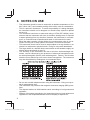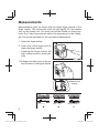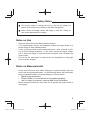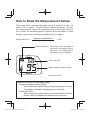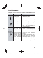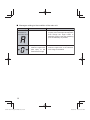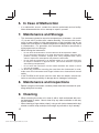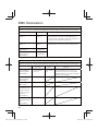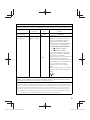
1
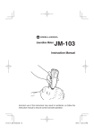
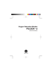
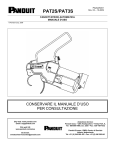
Oxygen Saturation Monitor
PULSOX™-2
Instruction Manual
9222-1731-14_P-2.indd i
09.8.20 11:03:21 AM
Safety Symbols
Warnings and precautions noted in this manual are indicated by the following markings, designed to prevent accidents caused by erroneous handling of the equipment.
This indicates text consisting of a warning or precaution relating to safety.
Please read the text carefully and use the equipment safely.
This indicates an action which is prohibited.
The prohibited action should never be carried out, under any circumstances.
This indicates instructions concerning an action.
Always follow the instructions carefully.
This indicates an action which is prohibited.
Never disassemble the product or unit.
This symbol indicates that has no alarm function is prescribed in
IEC60417-5319.
This symbol indicates type BF applied part.
The instrument provide a particular degree of protection against electric shock,
particularly the leakage current and reliability of the protective earth connection
with an F-TYPE APPLIED PART.
F-TYPE APPLIED PART indicates applied part isolated from all other parts of
the instrument to such a degree that the patient leakage current allowable in
single fault condition is not exceeded when a voltage equal to 1.1 times the
highest rated mains voltage is applied between the applied part and earth.
IPX4
This symbol indicates Splash-proof equipment.
Authorized Standards
For North America
UL, C_ UL:
C
SSIFIE
LA
D
Electrical Safety
E112871
For Europe
CE (Medical Device Directive):
This instrument complies with EN60601-1, EN60601-1-2,
EN ISO 14971, EN ISO 13485.
9222-1731-14_P-2.indd ii
09.8.20 11:03:21 AM
SAFETY PRECAUTIONS
To ensure correct use of this instrument, read the following points carefully
and adhere to them. After you have read this manual, keep it in a safe place
where it can be referred to anytime a question arises.
WARNING
(Failure to adhere to the following points may result in
death or serious injury.)
Do not use the instrument in places where flammable or combustible gases
(anesthetic gas etc.) are present. Doing so may cause a fire.
Do not put the batteries on a fire, short-circuit them, heat them or disassemble
them. Doing so may cause explosion or heat generation, resulting in fire or injury.
This device is designed to measure the oxygen saturation level (SpO2) and
the pulse rate. It should not be used as a warning device to detect cessation
of breathing or irregular breathing during sleep.
CAUTION
(Failure to adhere to the following points may result in
injury or damage to the instrument or other property.)
Do not use batteries other than those specified by KONICA MINOLTA.
When installing batteries in the instrument, make sure that they are
correctly oriented according to the (+) and (–) marks. For a model which use
more than one battery, do not mix new and old batteries, or mix batteries of
different types. Failure to adhere to these instructions may cause explosion
of the batteries or leakage of electrolyte, resulting in fire, injury or corrosion.
Do not place the instrument on an unstable or sloping surface. Doing so may
result in its dropping or overturning, causing injury. Take care not to drop the
instrument when carrying it.
Do not operate the instrument for long periods of time with a finger holder attached to a patient. Low-temperature burn, redness or rash may result. If you
feel pain or itchiness, stop use of the instrument immediately and consult a doctor. A doctor should also be consulted before using the instrument on infants,
those with peripheral blood circulation problems or those with sensitive skins.
If alkali fluid from the battery comes in contact with eyes, skin, or clothing,
immediately wash the affected area and see a physician for treatment.
Do not use wet batteries. Do not use instrument if the battery compartment contains water. Doing so may cause explosion or heat generation, resulting in fire or
injury.
Do not disassemble or modify the instrument. Doing so may cause a fire or electric shock.
1
1. BEFORE OPERATION
Safety Notes
CAUTION: U.S. Federal law restricts this device to sale by or on
the order of a physician.
The PULSOX-2 is a medical instrument, so instructions given by
a doctor must be adhered to.
The instrument is designed for measurement of the oxygen saturation (SpO2) of arterial blood and the pulse rate. Do not use
it for any other purposes, such as warning of sleep apnea and
breathing abnormalities.
Package Contents
Make sure that all the following items are supplied with the instrument.
1 PULSOX-2 main unit (×1)
2 Neck strap NS-M (×1)
3 AAA-size alkaline battery (×2)
Main Features
This pulse type oximeter emits light to the user’s finger to measure the
oxygen saturation (% SpO2) of arterial blood and the pulse rate.
•
Compact, lightweight and portable
The light weight, compactness, and portability of the PULSOX-2 allows
it to be used for inspection of both outpatients and inpatients. In addition, it is easily transported by both doctors and nurses for house calls
or home-care patients.
•
Battery-operated
The PULSOX-2 is operated by two AAA-size alkaline batteries.
2
9222-1731-14_P-2.indd Sec1:2
09.8.20 11:03:22 AM
2. NAMES OF PARTS
■ Main unit
Finger holder
Battery cover lock
Strap eyelet
Battery cover
Display
Thumb rest
Battery cover:
Battery cover lock:
Strap eyelet:
Finger holder:
Thumb rest:
Display:
Open or close this cover when replacing the
batteries with new ones.
It is used to lock the battery cover.
Attach the neck strap to this hook.
Holds finger when inserted for measurement.
A light source is located in the upper side, and
a sensor in the lower side.
Put the thumb here when you hold this instrument.
Displays measured value, pulse level meter
and error messages.
3
9222-1731-14_P-2.indd Sec1:3
09.8.20 11:03:22 AM
3. NOTES ON USE
•
•
•
•
•
•
•
•
•
•
•
This instrument should be used in areas with an ambient temperature of 0 to
40°C (32 to 104°F) and a relative humidity of 30 to 95%, with no condensation.
This is a precision instrument. To avoid the possibility of it being damaged,
the instrument should not be dropped nor should heavy objects be placed
on top of it.
This instrument conforms to water-seal rating of IPX4 (IEC 60529), which
ensures that the instrument will show no adverse damage even if exposed
to water splashing from any direction. However, the instrument is not waterproof, so it should never be washed with water or left immersed in water.
When the water remains in finger holder, the measurement value is not accurate.Turn the part of strap eyelet to the bottom, and remove the water.
This instrument should not be used in areas subject to strong vibrations, nor
should it be subjected to physical shock. Doing so may cause breakdown.
The finger holder is a delicate device and should not be handled roughly nor
should objects be placed on top of it.
The accuracy of this instrument, like that of all other dual-wavelength oximeters, can be influenced by the presence of abnormal hemoglobins such
as carboxyhemoglobin (HbCO) and methemoglobin. Tables 1 and 2 below
show the errors which may occur due to these hemoglobins. The instrument
may also be affected by cardiogreen or intravascular dyes.
Do not use a mobile telephone when using this instrument. Doing so may result in measurement error.
This instrument may interfere with magnetic resonance imaging (MRI) procedure.
The disposal method of AAA batteries varies according to local government
regulation.
Dispose of the battery according to the instructions given by local government
regulations or ask a specialized waste service company to dispose of it.
4
9222-1731-14_P-2.indd Sec1:4
09.8.20 11:03:22 AM
This equipment has been tested and found to comply with the limits for
medical devices to the IEC 60601-1-2:2001, Medical Device Directive
93/42/EEC . These limits are designed to provide reasonable protection against harmful interference in a typical medicitl installation. This
equipment generates, uses and can radiate radio frequency energy
and, if not installed and used in accordance with the instructions, may
cause harmful interference to other devices in the vicinity. However,
there is no guarantee that interference will not occur in a particular
installation. If this equipment does cause harmful interference to other
devices, which can be determined by turning the equipment off and on,
the user is encouraged to try to correct the interference by one or more
of the following measures:
• Reorient or relocate the receiving device.
• Increase the separation between the equipment.
• Connect the equipment into an outlet on a circuit different from
that to which the other device's are connected.
• Consult the manufacture or field service technician for help.
5
9222-1731-14_P-2.indd Sec1:5
09.8.20 11:03:22 AM
4. OPERATING METHOD
Preparations
(1) Installing Batteries
(Two AAA-size batteries are required.)
1. Push the battery cover, and unlock
the battery cover lock.
1
2. Open the battery cover.
3. Insert two AAA-size batteries into
the battery chamber.
2
3
4. Close the battery cover and hold it
with a finger.
4
6
9222-1731-14_P-2.indd Sec1:6
09.8.20 11:03:22 AM
5. Close the battery cover lock until it
clicks.
• The batteries will last approximately 80 hours.
• The battery mark will begin to
blink when the battery power is
low.
5
Notes on Use
•
Battery replacement is the Only User Serviceable item.
•
When replacing the batteries with new ones, do not mix battery types or
ages.
•
If the instrument will not be used for a long period of time, remove the
batteries from the battery chamber. Also remove the batteries as soon
as possible if they are dead.
(2) Installing the Neck Strap
By attaching the neck strap to the instrument, the instrument can
be hung from the neck.
1. Pass the neck strap through the
strap eyelet as shown in the figure.
7
9222-1731-14_P-2.indd Sec1:7
09.8.20 11:03:22 AM
Measurements
Measurements must be taken with the index finger placed in the
finger holder. This instrument must be held tightly. Put the thumb
only on the thumb rest. You must not put the thumb on other positions. Don't take the pressure which is unnecessary for the forefinger. Those are important for the accurate measurement.
1. Open the finger holder.
2. Insert the index finger and release the finger holder.
• Opening the finger holder will
start measurement automatically.
The finger should be put on the position shown in the figure below.
Measurement
display
Light Source
Sensor
Proper attachment
Finger is not sufficiently
inserted.
Finger is inserted too far.
Measurement cannot be taken.
8
9222-1731-14_P-2.indd Sec1:8
09.8.20 11:03:22 AM
Safety Notes
This finger holder is designed only for use on the fingers of
adults, so it should not be used on any other body parts.
Never secure the finger holder with tape or such like. Doing so
may cause hemostasia or dropsy.
Notes on Use
•
•
•
•
Remove nail polish before taking measurements.
If no measurement values are displayed, attach the finger holder to a
thinner finger to take measurements.
It may not be possible to take measurements in case of blood circulation or blood stream problems. In this case, remove the finger holder,
rub or warm the finger to improve blood circulation, then re-attach the
finger holder.
Do not use the instrument in areas where it is exposed to strong light
such as direct sunlight.
Notes on Measurements
•
Check that the pulse level meter changes in synchronization with the
pulse rate during measurements. In the following cases, the level meter
may not operate properly, hindering display of correct values.
• Rapid body movement
• Finger Holder is not attached to the patient properly.
• Arm or finger is pressed, causing bad blood circulation.
•
When using the instrument, take care not to expose the finger holder to
strong light.
9
9222-1731-14_P-2.indd Sec1:9
09.8.20 11:03:23 AM
Ending Measurements
1. Open the finger holder and remove the finger.
• Measurement will stop automatically, and the display will go
off after 10 seconds.
Notes on Use
•
If the instrument will not be used for a long period of time, remove the
batteries from the battery chamber.
10
9222-1731-14_P-2.indd Sec1:10
09.8.20 11:03:23 AM
How to Read the Measurement Values
Pulse level meter: Indicates the pulse level in 8 levels (0 to 10%, full
scale if 10% or higher). The pulse level is defined as follows. (For stable measurements, adjust the measuring point of the finger holder or
rub or warm the measuring point to improve blood circulation, so that
the pulse level meter constantly indicates level 2 or higher.)
Pulse level (%) =
Variable transmittance
Constant transmittance
× 100
Battery indication: The battery mark will begin to
blink when the battery power
level is low. (For details regarding batteries, refer to page 8.)
Pulse rate (P.R.)
Oxygen saturation value (SpO2)
Pulse level meter
Calculation method for displayed values
Oxygen saturation value (SpO2):
Value obtained by performing moving averaging for the last
5 seconds is updated and displayed every second.
Pulse rate (P.R.):
Value obtained by performing moving averaging for the last
8 pulse rates is updated and displayed every second.
11
9222-1731-14_P-2.indd Sec1:11
09.8.20 11:03:23 AM
Back Light
The backlight will light up automatically when the surroundings become dark.
When backlight isn’t turned by the bright surroundings, cover the
backlight sensor window with finger.
Backlight sensor window
• Once the backlight is lit, it will remain lit until measurement
stops.
• When battery mark is blinking, backlight isn’t turned on. Please
replace the battery.
12
9222-1731-14_P-2.indd Sec1:12
09.8.20 11:03:23 AM
Error Messages
■ Messages relating to connection of the finger holder and attachment to
the patient
Cause
Error Messages
•
Check that the finger holder is properly
attached to the patient.
Clean the light-source and sensor
sections.
Take measures to prevent direct entry
of strong light to the finger holder.
•
Pulse signal required •
for measurement is
not being received.
Check that the finger holder is properly
attached to the patient. If the finger
holder is properly attached but this
message still appears, the circulation in
the area being measured may not be
good. If this occurs, warm up the
measurement location.
•
The pulse is weak and •
the pulse signals
required for the measurement are not obtained. The measurement value is displayed, however, the
accuracy of the measurement values can •
not be guaranteed.
Thus, the measured
value must be considered as guidance
only.
Attach the finger holder to the body
correctly. If this message is displayed
when the unit is attached to the patient
correctly, the measurement conditions
are regarded as blood circulation or
other circulatory problems. If this
occurs, warm up the measurement
locations.
In particular, when the pulse is weak,
this error tends to occur. For improved
measurement accuracy, if the finger
holder is exposed to strong light, wrap it
with a piece of black cloth, etc. Also
make sure that the patient rests calmly
to avoid influence of body movement.
•
The Measurement Value and
flash alternately
Solution
Insufficient light for •
measurement..
Strong light enters the •
finger holder’s sensor
directory.
•
13
9222-1731-14_P-2.indd Sec1:13
09.8.20 11:03:23 AM
■ Messages relating to the condition of the main unit
Error Messages
Cause
Solution
•
Motion artifact
•
Attach the finger holder to the patient
properly. If this message still reappears
even though the finger holder is
attached properly, keep the measuring
point as stationary as possible.
•
The pulse rate ex- •
ceeds the upper limit
(250 bpm) of the
measurement range.
Measurement cannot be performed
when the upper limit of the measurement range is exceeded.
The Measurement Value and
14
9222-1731-14_P-2.indd Sec1:14
09.8.20 11:03:23 AM
5. TROUBLESHOOTING
■ Main Unit
Error Messages
•
•
Display disap- •
peared in the
middle
of
measurements.
No display appears when the •
finger
holder
was
opened
and the measurement
was
started.
Cause
Solution
•
Turn the POWER
switch OFF and replace the two batteries (AAA-size) with
new ones.
P.5
Are batteries oriented •
correctly (+ and marks)?
Make sure that the
batteries are oriented
correctly.
P.5
Is battery power exhausted?
15
9222-1731-14_P-2.indd Sec1:15
09.8.20 11:03:23 AM
6. In Case of Malfunction
•
If a malfunction occurs, contact the nearest authorized service facility.
Never disassemble the unit or attempt to repair it yourself.
7. Maintenance and Storage
•
•
This instrument should be stored at temperatures of between –10 and 60
°C (14 and 140°F) at 30 to 95% relative humidity. Do not store this instrument in areas subject to high temperatures or high humidity, and do not
subject this instrument to sudden temperature changes which may result
in condensation. For protection, this instrument should be stored with a
drying agent such as silica gel.
When storing the instrument:
•
•
•
•
•
•
Do not store the instrument in an area where it will be exposed to water.
Do not store the instrument in an area where direct sunlight, pressure, temperature, humidity, ventilation, sunlight, dust, strong magnetic fields, and/or
saline or sulphurous atmospheres may affect the instrument.
Do not store the instrument on an inclined surface or on a surface which may
be subject to vibrations or physical shock. (Also avoid vibrations or physical
shock during transportation.)
Do not store the instrument in areas where chemicals are stored or where
gas may be emitted.
To avoid any problems occurring the next time the instrument is used,
make sure the instrument and finger holders are cleaned and stored
safely.
If the PULSOX-2 will not be used for more than two weeks, remove batteries to avoid the possibility of damage due to leakage of electrolyte.
8. Maintenance and inspections
•
Before using the instrument, carefully check that the instrument is operating safely and correctly.
9. Cleaning
•
•
When cleaning the main unit, clean it with a cloth moistened with neutral detergent or water. Never clean it by any other methods or with any
kind of solvent.
When cleaning a finger holder, clean it using a soft cloth moistened with ethyl
alcohol or cationic soap, and wipe it off using a dry soft cloth or dry it naturally.
16
9222-1731-14_P-2.indd Sec1:16
09.8.20 11:03:24 AM
10. SPECIFICATIONS
PULSOX-2
■ Dual-wavelength pulse-type oximeter
■ Functions:
• Measuring range: SpO2: 0 to 100%
Pulse rate: 20 to 250 bpm
• Accuracy:
SpO2 ±2% (SpO2:70 to 100%, 1 S.D.)
Pulse rate: ±2 bpm
■ Display
Display type: Liquid crystal display
Oxygen saturation (SpO2)
Pulse rate number
Pulse level meter
Error messages
■ Operating temperature/humidity range
0 to 40°C (32 to 104°F); 30 to 95% relative humidity with no condensation
■ Storage temperature/humidity range
–10 to 60°C (14 to 140°F); 30 to 95% relative humidity with no condensation
■ Power
2 AAA-size batteries 3V
80mW
(This instrument can use about 80 hours continuously, when the use of the AAA alkaline battery.)
■ Dimensions (W × H × D)
69 × 60 × 28 mm
■ Weight
57 g
■ Accessory
Standard Accessory: Neck strap
■ Equipment Classification
• Protection against electric shock : Internally powered
• Type of applied part : BF
• Degree of protection against harmful ingress of water : Splashproof equipment (IPX4)
• Not suitability for use in the presence of flammable anaesthetic
mixture with air or oxygen or nitrous oxide.
• Mode of operation of Equipment : Continuous while in Use (IEC
60601-1)
17
9222-1731-14_P-2.indd Sec1:17
09.8.20 11:03:24 AM
11. REFERENCE
Measurement Principle
Oxygen Saturation Monitor PULSOX-2 is a photometric instrument that
non-invasively and continuously measures the oxyhemoglobin saturation of arterial blood (SpO2) and the pulse rate. SpO2 is described by
the equation:
SpO2 =
where
C (Hb):
C (HbO2):
C (HbO2)
C (HbO2) + C (Hb)
× 100 (% SpO2)
Concentration of reduced hemoglobin
Concentration of oxyhemoglobin
The light-absorption characteristics of reduced hemoglobin (Hb) are
very different from those of oxyhemoglobin. The PULSOX-2 measures the changes in the absorption of red and infrared lights passing
through the tissue to determine the SpO2 of the blood. Thus, this
method is free from the effects of skin color, muscles, bones, and
veins.
Spectral Absorption of Hb and HbO2
Infrared light
Absorption coefficient
Red light
18
9222-1731-14_P-2.indd Sec1:18
09.8.20 11:03:24 AM
Relation between Oxygen Saturation and Partial Pressure
The relation between oxygen saturation (SpO2, %) and oxygen partial
pressure (PaO2, Torr or mmHg) is shown in the graph below. SpO2 is
the oxygen saturation as measured by pulse oximeters.
Oxygen Saturation vs. Oxygen Partial Pressure
Oxygen Partial Pressure SpO2
%
100
90
85
80
70
60
50
40
Adult hemoglobin
30
pH=7.4
37°C
20
10
0
10
20
30
40
50
60
70
80
PaO2
Oxygen Partial Pressure
90
100
110
Torr
(mmHg)
The curve of the above graph may shift to the right or left according to
the pH of the blood or the body temperature. (Shift to right: acidosis,
high body temperature; shift to left: alkalosis, low body temperature)
19
9222-1731-14_P-2.indd Sec1:19
09.8.20 11:03:24 AM
EMC Declaration
Guidance and manufacture s declaration - electromagnetic emissions
The Model PULSOX-2 is intended for use in the electromagnetic environment specified below. The
customer or the user of the Model PULSOX-2 should assure that it is used in such an environment.
Emissions test
Compliance
CISPR 11
Electriomagnetic environment - guidance
The Model PULSOX-2 uses RF energy only for its
RF emissions
Group 1
internal function. Therefore its RF emissions are
very low and are not likely to cause any interference
in nearby electromagnetic equipment.
The Model PULSOX-2 is suitable for use in all
RF emissions
CISPR 11
Class B
Harmonic emissions
IEC61000-3-2
establishments, including domestic establishments.
Not applicable
Voltage fluctuations/
flicker emissions
Not applicable
IEC61000-3-3
Guidance and manufacture s declaration - electromagnetic immunity
The Model PULSOX-2 is intended for use in the electromagnetic environment specified below. The
customer or the user of the Model PULSOX-2 should assure that it is used in such an environment.
Immunity test
IEC 60601
Test level
Compliance
level
Electromagnetic environment guidance
Electromagnetic
6 kV contact
6 kV contact
Floors should be wood, concrete or
Discharge (ESD)
8 kV air
8 kV
ceramic tile, if fllors are covered with
synthetic materisl, the relative humidity
IEC61000-4-2
should be at least 30%.
Electrical fast
Not applicable
Transient/burst
IEC61000-4-4
Surge
Not applicable
IEC61000-4-5
Voltage dips, short
Not applicable
Interruptions and
Voltage variations
on power supply
Input lines
IEC61000-4-11
Power frequency
Not applicable
(50/60Hz) magnetic
field
IEC61000-4-8
20
9222-1731-14_P-2.indd Sec1:20
09.8.20 11:03:24 AM
Guidance and manufacture s declaration - electromagnetic immunity
The Model PULSOX-2 is intended for use in the electromagnetic environment specified below. The
customer or the user of the Model PULSOX-2 should assure that it is used in such an environment.
Immunity test
Conducted RF
IEC 60601
Test level
Compliance
level
Electromagnetic environment guidance
Not applicable
IEC61000-4-6
Radiated RF
3 V/m
Portable and mobile RF communications
IEC61000-4-3
80MHz to 2.5GHz
equipment should be used no closer to
any part of the PULSOX-2, than the
recommended separation distance
calculated from the equation applicable
to the frequency of the transmitter.
Recommended separation distance
E㲋1 80MHz to 800MHz
E㲋1 800MHz to 2.5GHz
where P is the maximum output power
rating of the transmitter in watts (W)
according to the transmitter
manufacturer and d is the recommended
3 V/m
separation distance inmeters (m).
Field strength from fixed RF transmitters,
as determined by an electromagnetic site
survey a, should be less than the
compliance level in each frequency
range b.
Interference may occur in the vicinity of
equipment marked with the following
symbol:
NOTE 1 At 80MHz and 800MHz, the higher frequency range applies.
NOTE 2 These guidelines may not apply in all situations. Electromagnetic propagation is affected
by absorption and reflection from structures, objects and people.
a
Field strengths from fixed transmitters, such as base stations for radio (cellular/cordless) telephone and land
mobile radios, amateur radio, AM and FM radio broadcast and TV broadcast cannot be predicted theoretically with
accuracy. To assess the electromagnetic environment due to fixed RF transmitters, an electromagnetic site survey
should be considered. If the measured field strength in the location in which the PULSOX-2 is used exceeds the
applicable RF compliance level above, the PULSOX-2 should be observed to verify normal operation. If abnormal
performance is observed, additional measures may be necessary, such as reorienting or relocating the PULSOX-2.
b
Over the frequency range 150kHz to 80MHz, field strengths should be less than 3V/m.
21
9222-1731-14_P-2.indd Sec1:21
09.8.20 11:03:24 AM
3-91, Daisen-nishimachi, Sakai-ku, Sakai-shi, Osaka 590-8551, Japan
9222-1731-16
© 2002-2013 KONICA MINOLTA, INC.
BDEAPX Printed in Japan