1
OC132--1.qxp 1.11.8 10:42 AM Page 1
2001
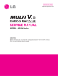
SPLIT-TYPE, HEAT PUMP AIR CONDITIONERS
No. OC132
REVISED EDITION-A
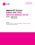
TECHNICAL & SERVICE MANUAL
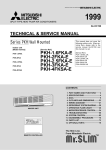
Series PKH Wall Mounted
Indoor unit
[ Model names ]
[ Service Ref. ]
PKH-2FKA3
PKH-2.5FKA2
PKH-2.5FKA3
PKH-3FKA2
PKH-3FKA3
PKH-4FKSA2
PKH-4FKSA3
PKH-2FKA
PKH-2.5FKA
PKH-3FKA
PKH-4FKSA
• PKH-2.5FKA3, PKH-3FKA3 and
PKH-4FKSA3 are added in
REVISED EDITION-A.
• Please void OC132 .
• This manual does not cover
outdoor units. When servicing
them, please refer to the service
manual No.OC128 REVISED
EDITION-C and this manual in
a set.
[Service Ref.]
PUH-2VKA2,
PUH-2NKA1,
PUH-2.5VKA2,
PUH-2.5NKA1,
PUH-3VKA2,
PUH-3YKA2,
PUH-3YKA4,
PUH-3NKA1,
PUH-4YKSA3,
PUH-4TKSA1
PUH-2VKA3,
PUH-2NKA2,
PUH-2.5VKA3,
PUH-2.5NKA2,
PUH-3VKA3,
PUH-3YKA3,
PUH-3NKA2,
PUH-4YKSA4,
CONTENTS
Indoor unit
CHECK
FILTER
CHECK MODE
TEST RUN
REMOTE CONTROLLER
1. TECHNICAL CHANGES·······················2
2. PART NAMES AND FUNCTIONS ········3
3. SPECIFICATIONS·································5
4. DATA ···················································13
5. OUTLINES AND DIMENSIONS··········20
6. WIRING DIAGRAM·····························24
7. REFRIGERANT SYSTEM DIAGRAM ······26
8. OPERATION FLOW-CHART ··············28
9. MICROPROCESSOR CONTROL·······32
10. TROUBLESHOOTING ························54
11. SYSTEM CONTROL ···························63
12. DISASSEMBLY PROCEDURE ···········68
13. PARTS LIST········································71
14. OPTIONAL PARTS ·····························80
OC132--1.qxp 1.11.8 10:42 AM Page 2
1
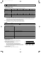
TECHNICAL CHANGES
● PKH-2.5FKA2 ➔ PKH-2.5FKA3
● PKH-3FKA2 ➔ PKH-3FKA3
● PKH-4FKSA2 ➔ PKH-4FKSA3
•NOSE shape has changed.
•UNDER PLATE shape has changed.
•TOP PLATE shape has changed.
•DRAIN PAN shape has changed.
•BOX ASSEMBLY shape has changed.
•The specifications of these power supply voltages have been added: 50Hz 220-230-240V;
50Hz 380-400-415V.
2
OC132--1.qxp 1.11.8 10:42 AM Page 3
2
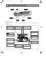
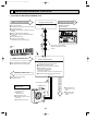
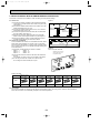
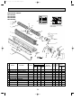
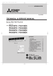
PART NAMES AND FUNCTIONS
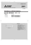
● Indoor Unit
Air intake
Filter
Room air is suctioned
in here.
Air intake grille
(Removes dust and dirt from the intake air.)
Guide vane
Auto vane
Air flow can be changed to horizontally
by moving the Guide vane to the left or
right.
Air outlet
Air outlet
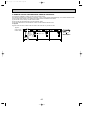
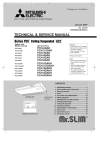
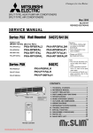
● Remote controller
● Once the operation of the unit is set, subsequent operations can only be performed by pressing the ON/OFF button repeatedly.
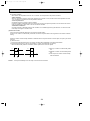
● Operation buttons
w button
q button
This switches between continuous
operation and the timer operation
This sets or switches the current
time, start time and stop time.
button
The sets the ventilation fan speed.
ON/OFF button
This switches between the operation
and stop modes each time it is
pressed. The lamp on this button
lights during operation.
button
Press this button to switch the cooler
electronic dry (dehumidify), automatic and heater modes.
FILTER
CHECK
CHECK MODE
TEST RUN
j button
This adjusts the vertical angle of the
ventilation.
i TEMP button
This sets the room temperature. The
temperature setting can be performed in 1°C units.
Setting range :
Cooler 19°C to 30°C
Heater 17°C to 28°C
The model name of the remote controller is indicated.
PAR-JH241KA(2.5 ~ 4)
PAR-JH150KA(2)
FILTER button
This resets the filter service indication display
CHECK-TEST RUN button
button
This switches the horizontal fan
motion ON and OFF.
(This button does not operate in this
model.)
3
Only press this button to perform an
inspection check or test operation.
Do not use it for normal operation
OC132--1.qxp 1.11.8 10:42 AM Page 4
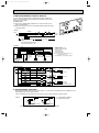
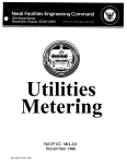
● Display
CENTRALLY
CONTROLLED display
r display
This indicates when the unit is controlled by optional features such as
central control type remote controller.
The current time , start time and stop
time can be displayed in ten second
intervals by pressing the time switch
button. The start time or stop time is
always displayed during the timer
operation.
display
The selected fan speed is displayed.
In this display example on
the bottom left, a condition
where all display lamps light
is shown for explanation purposes although this differs
from actual operation.
j display
This displays the air direction.
—88°C display
w display
This indicates when the continuous
operation and time operation modes
are set.
It also display the time for the timer
operation at the same time as when
it is set.
FILTER
CHECK
CHECK MODE
The temperature of the suction air is
displayed during operation. The display range is 8° to 39°C. The display
flashes 8°C when the actual temperature is less than 8° and flashes
39°C when the actual temperature is
greater than 39°C.
TEST RUN
OPERATION MODE display
This indicates the operation mode.
Operation lamp
STANDBY display
This lamp lights during operation,
goes off when the unit stops and
flashes when a malfunction occurs.
This indicates when the standby
mode is set from the time the sleep
operation starts until the heating air
is discharged.
CHECK MODE
DEFROST display
This indicates when the defrost operation is performed.
display
FILTER
This lamp lights when the filter need
to be cleaned.
TEST RUN
display
This display lights in the check mode
or when a test operation is performed.
CHECK display
—88°C display
This indicates when a malfunction
has occurred in the unit which should
be checked.
This displays the selected setting
temperature.
Display
This lamp lights when electricity is
supplied to the unit.
Caution
● Only the
display lights when the unit is stopped and power supplied to the unit.
● When power is turned ON for the first time the (CENTRAL CTRL) display appears to go off momentarily but this is not a
malfunction.
● When the central control remote control unit, which is sold separately, is used the ON-OFF button,
button and i
TEMP button do not operate.
● “NOT AVAILABLE” is displayed when the
button is pressed. This indicates that this room unit is not equipped with.
4
OC132--1.qxp 1.11.8 10:42 AM Page 5
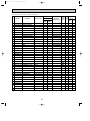
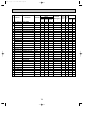
3
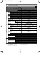
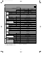
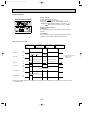
SPECIFICATIONS
50Hz
Service Ref.
Item
Function
Capacity
W
Btu/h
kW
REFRIGERANT PIPING
OUTDOOR UNIT
INDOOR UNIT
Total input
Service Ref.
Power supply(phase,cycle,voltage)
Input
kW
Running current
A
Starting current
A
External finish
Heat exchanger
Fan
Fan(drive) ✕ No.
Fan motor output
kW
Airflow(Low-High)
m3/X<CFM>
External static pressure
Pa(mmAq)
Booster heater
kW
Operation control & Thermostat
Noise level(Low-High)
>
Cond. drain connection. O.D.
A<in.>
W
A<in.>
Dimensions
D
A<in.>
H
A<in.>
Weight
kg<lbs>
Service Ref.
Power supply (phase, cycle, voltage)
Input
kW
Running current
A
Staring current
A
External finish
Refrigerant control
Compressor
Model
Motor output
kW
Starter type
Protection devices
Heat exchanger
Fan(drive)✕No.
Fan
Fan motor output
kW
Airflow
m3/X<CFM>
Defrost method
Noise level
>
A<in.>
W
Dimensions
A<in.>
D
A<in.>
H
Weight
kg<lbs>
Refrigerant
kg<lbs>
Charge
A<in.>
Liquid
Pipe size O.D.
A<in.>
Gas
Indoor side
Connection method
Outdoor side
Height difference
Between the indoor & outdoor unit
Piping length
Note 1. Rating Conditions (JIS B 8616)
Cooling : Indoor : D.B. 27°C (80°F), W.B. 19°C (66°F)
Outdoor : D.B. 35°C (95°F), W.B. 24°C (75°F)
Heating : Indoor : D.B. 20°C (68°F)
Outdoor : D.B. 7°C (45°F), W.B. 6°C (43°F)
PKH-2FKA3
Cooling
5,500
18,800
2.27
PKH-2FKA3
Single Phase, 50Hz, 220-230-240V
0.07
0.07
0.32
0.32
0.40
0.40
Munsell 3.4Y 7.7/0.8(White)
Plate fin coil
Line flow(direct) ✕ 1
0.030
10-13<353-459>
0(direct blow)
—
Remote controller & built-in
36-43
20<13/16>
1,250<49-3/16>
200<7-7/8>
300<11-13/16>
18<40>
PUH-2VKA2 PUH-2VKA3
Single Phase, 50Hz, 220-230-240V
2.20
2.22
9.86
9.95
45
Munsell 5Y 7/1
Capillary tube
Hermetic
NH38VMD
1.7
Line start
Internal thermostat, HP switch
Plate fin coil
Propeller (direct) ✕ 1
0.065
45<1.590>
Reverse cycle
49
870(34-1/4)
295+24<11-5/8 add 1>
650<25-5/8>
64<141>
R22
2.2<4.9>
9.52<3/8>
15.88<5/8>
Flared
Flared
Max. 40m
Max. 40m
Note 2. Above data based on indicated voltage
Indoor Unit Single phase 240V 50Hz
Outdoor Unit Single phase 240V 50Hz
5
Heating
6,250
21,300
2.29
OC132--1.qxp 1.11.8 10:42 AM Page 6
50Hz
Service Ref.
PKH-2.5FKA2 PKH-2.5FKA3
Item
Function
Capacity
Cooling
Heating
6,500
7,200
22,200
24,600
2.56
2.33
PKH-2.5FKA2 PKH-2.5FKA3
Single Phase, 50Hz, 220-230-240V
0.095
0.095
0.44
0.44
0.80
0.80
Munsell 3.4Y 7.7/0.8(White)
Plate fin coil
Line flow(direct) ✕ 2
0.040
15-20<530-706>
0(direct blow)
—
Remote controller & built-in
39-45
20<13/16>
1,400<55-1/8>
235<9-1/4>
340<13-3/8>
26<57>
PUH-2.5VKA2 PUH-2.5VKA3
Single Phase, 50Hz, 220-230-240V
2.46
2.23
10.68
9.78
52
Munsell 5y 7/1
Capillary tube
Hermetic
NH41VMD
2.0
Line start
Internal thermostat, HP switch
Plate fin coil
Propeller (direct) ✕ 1
0.085
50<1,764>
Reverse cycle
52
870(34-1/4)
295+24<11-5/8 add 1>
850<33-7/16>
64<150>
R22
2.8<6.2>
9.52<3/8>
15.88<5/8>
Flared
Flared
Max. 50m
Max. 50m
W
Btu/h
kW
REFRIGERANT PIPING
OUTDOOR UNIT
INDOOR UNIT
Total input
Service Ref.
Power supply(phase,cycle,voltage)
Input
kW
Running current
A
Starting current
A
External finish
Heat exchanger
Fan
Fan(drive) ✕ No.
Fan motor output
kW
Airflow(Low-High)
m3/X<CFM>
External static pressure
Pa(mmAq)
Booster heater
kW
Operation control & Thermostat
Noise level(Low-High)
>
Cond. drain connector. O.D.
A<in.>
W
A<in.>
Dimensions
D
A<in.>
H
A<in.>
Weight
kg<lbs>
Service Ref.
Power supply (phase, cycle, voltage)
Input
kW
Running current
A
Staring current
A
External finish
Refrigerant control
Compressor
Model
Motor output
kW
Starter type
Protection devices
Heat exchanger
Fan
Fan(drive)✕No.
Fan motor output
kW
Airflow
m3/X<CFM>
Defrost method
Noise level
>
A<in.>
W
Dimensions
A<in.>
D
A<in.>
H
Weight
kg<lbs>
Refrigerant
kg<lbs>
Charge
A<in.>
Liquid
Pipe size O.D.
A<in.>
Gas
Indoor side
Connection method
Outdoor side
Height difference
Between the indoor & outdoor unit
Piping length
Note 1. Rating Conditions (JIS B 8616)
Cooling : Indoor : D.B. 27°C (80°F), W.B. 19°C (66°F)
Outdoor : D.B. 35°C (95°F), W.B. 24°C (75°F)
Heating : Indoor : D.B. 20°C (68°F)
Outdoor : D.B. 7°C (45°F), W.B. 6°C (43°F)
Note 2. Above data based on indicated voltage
Indoor Unit Single phase 240V 50Hz
Outdoor Unit Single phase 240V 50Hz
6
OC132--1.qxp 1.11.8 10:42 AM Page 7
50Hz
Service Ref.
Item
Function
Capacity
Cooling
Heating
7,900
9,100
27,000
31,000
3.25
3.04
PKH-3FKA2 PKH-3FKA3
Single Phase, 50Hz, 220-230-240V
0.095
0.095
kW
0.44
0.44
A
0.80
0.80
A
Munsell 3.4Y 7.7/0.8(White)
Plate fin coil
Line flow(direct) ✕ 2
0.040
kW
15-20<530-706>
m3/X<CFM>
0(direct blow)
Pa(mmAq)
—
kW
Remote controller & built-in
39-45
>
20<13/16>
A<in.>
1,400<55-1/8>
A<in.>
235<9-1/4>
A<in.>
340<13-3/8>
A<in.>
26<57>
kg<lbs>
PUH-3VKA2 PUH-3VKA3 / PUH-3YKA2 PUH-3YKA3 PUH-3YKA4
Single Phase, 50Hz, 220-230-240V/3Phase, 50Hz, 380-400-415V(4wires)
3.15/3.15
2.94/2.94
kW
13.82/5.16
12.89/4.81
A
58/37
A
Munsell 5Y 7/1
Capillary tube
Hermetic
W
Btu/h
kW
REFRIGERANT PIPING
OUTDOOR UNIT
INDOOR UNIT
Total input
Service Ref.
Power supply(phase,cycle,voltage)
Input
Running current
Starting current
External finish
Heat exchanger
Fan(drive) ✕ No.
Fan
Fan motor output
Airflow(Low-High)
External static pressure
Booster heater
Operation control & Thermostat
Noise level(Low-High)
Cond. drain conn. O.D.
W
Dimensions
D
H
Weight
Service Ref.
Power supply (phase, cycle, voltage)
Input
Running current
Staring current
External finish
Refrigerant control
Compressor
Model
Motor output
kW
Starter type
Protection devices
Heat exchanger
Fan
Fan(drive)✕No.
Fan motor output
kW
Airflow
m3/X<CFM>
Defrost method
Noise level
>
A<in.>
W
Dimensions
A<in.>
D
A<in.>
H
Weight
kg<lbs>
Refrigerant
kg<lbs>
Charge
A<in.>
Liquid
Pipe size O.D.
A<in.>
Gas
Indoor side
Connection method
Outdoor side
Height difference
Between the indoor & outdoor unit
Piping length
Note 1. Rating Conditions (JIS B 8616)
Cooling : Indoor : D.B. 27°C (80°F), W.B. 19°C (66°F)
Outdoor : D.B. 35°C (95°F), W.B. 24°C (75°F)
Heating : Indoor : D.B. 20°C (68°F)
Outdoor : D.B. 7°C (45°F), W.B. 6°C (43°F)
PKH-3FKA2 PKH-3FKA3
Note 2. Above data based on indicated voltage
Indoor Unit Single phase 240V 50Hz
Outdoor Unit Single phase 240V 50Hz
3 phase 415V 50Hz
7
w
2.2/2.4
Line start
Internal thermostat, HP switch/Thermal relay, thermal switch
Plate fin coil
Propeller (direct) ✕ 1
0.085
50<1,764>
Reverse cycle
52
870(34-1/4)
295+24<11-5/8 add 1>
850<33-7/16>
75<165>
R22
3.2<7.1>
9.52<3/8>
15.88<5/8>
Flared
Flared
Max. 50m
Max. 50m
w PUH-3VKA2, PUH-3VKA3 ...... NH52VDA
PUH-3YKA2, .......................... NH52YDA
PUH-3YKA3, PUH-3YKA4 .... NH52YDE
OC132--1.qxp 1.11.8 10:42 AM Page 8
50Hz
Service Ref.
Item
Function
Capacity
W
Btu/h
kW
REFRIGERANT PIPING
OUTDOOR UNIT
INDOOR UNIT
Total input
Service Ref.
Power supply(phase,cycle,voltage)
Input
kW
Running current
A
Starting current
A
External finish
Heat exchanger
Fan(drive) ✕ No.
Fan
Fan motor output
kW
Airflow(Low-High)
m3/X<CFM>
External static pressure
Pa(mmAq)
Booster heater
kW
Operation control & Thermostat
Noise level(Low-High)
>
Cond. drain connector. O.D.
A<in.>
W
A<in.>
Dimensions
D
A<in.>
H
A<in.>
Weight
kg<lbs>
Service Ref.
Power supply (phase, cycle, voltage)
Input
kW
Running current
A
Staring current
A
External finish
Refrigerant control
Compressor
Model
Motor output
kW
Starter type
Protection devices
Heat exchanger
Fan(drive)✕No.
Fan
Fan motor output
kW
Airflow
m3/X<CFM>
Defrost method
Noise level
>
A<in.>
W
Dimensions
A<in.>
D
A<in.>
H
Weight
kg<lbs>
Refrigerant
kg<lbs>
Charge
A<in.>
Liquid
Pipe size O.D.
A<in.>
Gas
Indoor side
Connection method
Outdoor side
Height difference
Between the indoor & outdoor unit
Piping length
Note 1. Rating Conditions (JIS B 8616)
Cooling : Indoor : D.B. 27°C (80°F), W.B. 19°C (66°F)
Outdoor : D.B. 35°C (95°F), W.B. 24°C (75°F)
Heating : Indoor : D.B. 20°C (68°F)
Outdoor : D.B. 7°C (45°F), W.B. 6°C (43°F)
PKH-4FKSA2 PKH-4FKSA3
Cooling
Heating
9,500
10,700
32,400
36,500
3.31
3.30
PKH-4FKSA2 PKH-4FKSA3
Single Phase, 50Hz, 220-230-240V
0.114
0.114
0.53
0.53
0.90
0.90
Munsell 3.4Y 7.7/0.8(White)
Plate fin coil
Line flow(direct) ✕ 2
0.070
22-28<777-989>
0(direct blow)
—
Remote controller & built-in
41-46
20<13/16>
1,680<66-1/8>
235<9-1/4>
340<13-3/8>
30<66>
PUH-4YKSA3 PUH-4YKSA4
3, 50Hz, 380-400-415V(4wires)
3.20
3.19
5.24
5.22
40
Munsell 5Y 7/1
Capillary tube
Hermetic
PUH-4YKSA3:NH56YDA PUH-4YKSA4:NH56YDE
2.7
Line start
Thermal relay, thermal switch, HP switch, anti-phase protector
Plate fin coil
Propeller (direct) ✕ 2
0.065+0.065
95<3,350>
Reverse cycle
54
870(34-1/4)
295+24<11-5/8 add 1>
1,258<49-1/2>
94<207>
R22
4.2<9.2>
9.52<3/8>
19.05<3/4>
Flared
Flared
Max. 50m
Max. 50m
Note 2. Above data based on indicated voltage
Indoor Unit Single phase 240V 50Hz
Outdoor Unit
3 phase 415V 50Hz
8
OC132--1.qxp 1.11.8 10:42 AM Page 9
60Hz
Service Ref.
Item
PKH-2FKA3
Cooling
5,800/5,100
19,800/17,400
2.49/2.91
Function
W
Btu/h
kW
Capacity
Total input
Service Ref.
Power supply(Phase, cycle, voltage)
Input
Running current
Starting current
External finish
Heat exchanger
Fan(drive)oNo.
Fan
Fan motor output
Airflow(Low-High)
External static pressure
Booster heater
Operation control & Thermostat
Noise level(Low-High)
Cond. drain connection O.D.
REFRIGERANT
PIPING
Weight
Refrigerant
Charge
Munsell 3.4Y 7.7/0.8(White)
Plate fin coil
Line flow (direct) o 1
0.030
10-13<353-459>
0<direct blow>
—
Remote controller & built-in
36-43
20<13/16>
1,250<49-3/16>
200<7-7/8>
300<11-13/16>
18<40>
PUH-2NKA1 PUH-2NKA2
Single, 60Hz, 220V
kW
K/min (CFM)
mmAq, Pa
kW
W
D
H
dB
mm(in.)
mm(in.)
mm(in.)
mm(in.)
kg(lbs)
2.41/2.83
11.07/12.99
54
kW
A
A
kW
K/min (CFM)
dB
mm(in.)
mm(in.)
mm(in.)
kg(lbs)
kg(lbs)
Liquid
mm(in.)
Pipe size O.D.
Gas
mm(in.)
Indoor side
Connection method
Outdoor side
Height difference
Between the indoor & outdoor units
Piping length
Notes : w1 Rating conditions
(INDOOR)
Cooling : D.B. 27:, W.B. 19:
(OUTDOOR) Cooling : D.B. 35:
w2 Rating conditions
(INDOOR)
Cooling : D.B. 29:, W.B. 19:
(OUTDOOR) Cooling : D.B. 46:
2.45
11.2
54
Munsell 5Y 7/1
Capillary tube
Hermetic
NHJ33NBD
1.5
Line start
Inner thermostat
Plate fin coil
Propeller (direct) o 1
0.065
45<1,590>
Reverse cycle
49
870<34-1/4>
295+24 <11-5/8 add 1>
650 <25-5/8>
66.5<146>
R22
2.2<4.8>
9.52 <3/8>
15.88 <5/8>
Flared
Flared
Max. 40m
Max. 40m
kW
W
D
H
0.08
0.37
0.50
0.08
0.37
0.50
kW
A
A
Weight
Service Ref.
Power supply(Phase, cycle, voltage)
Input
Running current
Starting current
External finish
Refrigerant control
Compressor
Model
Motor output
Starter type
Protection devices
Heat exchanger
Fan(drive)oNo.
Fan
Fan motor output
Airflow
Defrost method
Noise level
Dimensions
Heating
6,600
22,500
2.53
PKH-2FKA3
Single. 60Hz. 220V
INDOOR UNIT
OUTDOOR UNIT
Dimensions
W1/ W2
Heating : D.B. 21:
Heating : D.B. 7:, W.B. 6:
9
W2
OC132--1.qxp 1.11.8 10:42 AM Page 10
60Hz
Service Ref.
Item
Function
W
Btu/h
kW
Capacity
Total input
Service Ref.
Power supply(Phase, cycle, voltage)
Input
Running current
Starting current
External finish
Heat exchanger
Fan(drive)oNo.
Fan
Fan motor output
Airflow(Low-High)
External static pressure
Booster heater
Operation control & Thermostat
Noise level(Low-High)
Cond. drain connection O.D.
INDOOR UNIT
kW
A
A
OUTDOOR UNIT
Dimensions
W
D
H
Weight
Service Ref.
Power supply(Phase, cycle, voltage)
Input
Running current
Starting current
External finish
Refrigerant control
Compressor
Model
Motor output
Starter type
Protection devices
Heat exchanger
Fan(drive)oNo.
Fan
Fan motor output
Airflow
Defrost method
Noise level
Dimensions
REFRIGERANT
PIPING
kW
K/min (CFM)
mmAq, Pa
kW
Weight
Refrigerant
Charge
dB
mm(in.)
mm(in.)
mm(in.)
mm(in.)
kg(lbs)
kW
A
A
kW
kW
K/min (CFM)
W
D
H
dB
mm(in.)
mm(in.)
mm(in.)
kg(lbs)
kg(lbs)
Liquid
mm(in.)
Pipe size O.D.
Gas
mm(in.)
Indoor side
Connection method
Outdoor side
Height difference
Between the indoor & outdoor units
Piping length
Notes : w1 Rating conditions
(INDOOR)
Cooling : D.B. 27:, W.B. 19:
(OUTDOOR) Cooling : D.B. 35:
w2 Rating conditions
(INDOOR)
Cooling : D.B. 29:, W.B. 19:
(OUTDOOR) Cooling : D.B. 46:
PKH-2.5FKA2 PKH-2.5FKA3
Cooling
w1/ w2
7,000/5,900
23,900/20,100
3.01/3.53
PKH-2.5FKA2 PKH-2.5FKA3
Single. 60Hz. 220V
0.095
0.44
0.70
Munsell 3.4Y 7.7/0.8(White)
Plate fin coil
Line flow (direct) o 2
0.040
15-20<530-706>
0<direct blow>
—
Remote controller & built-in
39-45
20<13/16>
1,400<55-1/8>
235<9-1/4>
340<13-3/8>
26<57>
PUH-2.5NKA1 PUH-2.5NKA2
Single, 60Hz, 220V
2.91/3.43
13.50/15.75
58
Munsell 5Y 7/1
Capillary tube
Hermetic
NHJ38NBD
1.7
Line start
Inner thermostat
Plate fin coil
Propeller (direct) o 1
0.085
50<1,764>
Reverse cycle
52
870<34-1/4>
295+24 <11-5/8 add 1>
850<33-7/16>
74<163>
R22
2.8<6.2>
9.52 <3/8>
15.88 <5/8>
Flared
Flared
Max. 50m
Max. 50m
Heating : D.B. 21:
Heating : D.B. 7:, W.B. 6:
10
Heating
8,000
27,300
2.90
0.095
0.44
0.70
2.80
13.0
58
w2
OC132--1.qxp 1.11.8 10:42 AM Page 11
60Hz
Service Ref.
Item
PKH-3FKA2 PKH-3FKA3
Cooling
7,800/6,900
26,600/23,500
3.62/4.23
Function
W
Btu/h
kW
Capacity
Total input
Service Ref.
Power supply(Phase, cycle, voltage)
Input
Running current
Starting current
External finish
Heat exchanger
Fan(drive)oNo.
Fan
Fan motor output
Airflow(Low-High)
External static pressure
Booster heater
Operation control & Thermostat
Noise level(Low-High)
Cond. drain connection O.D.
REFRIGERANT
PIPING
Weight
Refrigerant
Charge
Munsell 3.4Y 7.7/0.8(White)
Plate fin coil
Line flow (direct) O 2
0.040
15-20<530-706>
0<direct blow>
—
Remote controller & built-in
39-45
20<13/16>
1,400<55-1/8>
235<9-1/4>
340<13-3/8>
26<57>
PUH-3NKA1 PUH-3NKA2
Single, 60Hz, 220V
kW
K/min (CFM)
mmAq, Pa
kW
W
D
H
dB
mm(in.)
mm(in.)
mm(in.)
mm(in.)
kg(lbs)
3.52/4.13
16.49/18.77
80
kW
A
A
kW
K/min (CFM)
dB
mm(in.)
mm(in.)
mm(in.)
kg(lbs)
kg(lbs)
Liquid
mm(in.)
Pipe size O.D.
Gas
mm(in.)
Indoor side
Connection method
Outdoor side
Height difference
Between the indoor & outdoor units
Piping length
Notes : w1 Rating conditions
(INDOOR)
Cooling : D.B. 27:, W.B. 19:
(OUTDOOR) Cooling : D.B. 35:
w2 Rating conditions
(INDOOR)
Cooling : D.B. 29:, W.B. 19:
(OUTDOOR) Cooling : D.B. 46:
3.33
15.6
80
Munsell 5Y 7/1
Capillary tube
Hermetic
NHJ47NAD
2.2
Line start
Inner thermostat
Plate fin coil
Propeller (direct) o 1
0.085
50<1,764>
Reverse cycle
52
870<34-1/4>
295+24 <11-5/8 add 1>
850<33-7/16>
78<172>
R22
3.2<7.1>
9.52 <3/8>
15.88 <5/8>
Flared
Flared
Max. 50m
Max. 50m
kW
W
D
H
0.095
0.44
0.70
0.095
0.44
0.70
kW
A
A
Weight
Service Ref.
Power supply(Phase, cycle, voltage)
Input
Running current
Starting current
External finish
Refrigerant control
Compressor
Model
Motor output
Starter type
Protection devices
Heat exchanger
Fan(drive)oNo.
Fan
Fan motor output
Airflow
Defrost method
Noise level
Dimensions
Heating
9,500
32,400
3.43
PKH-3FKA2 PKH-3FKA3
Single. 60Hz. 220V
INDOOR UNIT
OUTDOOR UNIT
Dimensions
w1/ w2
Heating : D.B. 21:
Heating : D.B. 7:, W.B. 6:
11
w2
OC132--1.qxp 1.11.8 10:42 AM Page 12
60Hz
Service Ref.
Item
Function
W
Btu/h
kW
Capacity
Total input
Service Ref.
Power suppl(Phase, cycle, voltage)
Input
Running current
Starting current
External finish
Heat exchanger
Fan(drive)oNo.
Fan
Fan motor output
Airflow(Low-High)
External static pressure
Booster heater
Operation control & Thermostat
Noise level(Low-High)
Cond. drain connection O.D.
INDOOR UNIT
kW
A
A
OUTDOOR UNIT
Dimensions
W
D
H
Weight
Service Ref.
Power supply(Phase, cycle, voltage)
Input
Running current
Starting current
External finish
Refrigerant control
Compressor
Model
Motor output
Starter type
Protection devices
Heat exchanger
Fan(drive)oNo.
Fan
Fan motor output
Airflow
Defrost method
Noise level
Dimensions
REFRIGERANT
PIPING
kW
K/min (CFM)
mmAq, Pa
kW
Weight
Refrigerant
Charge
dB
mm(in.)
mm(in.)
mm(in.)
mm(in.)
kg(lbs)
kW
A
A
kW
kW
K/min (CFM)
W
D
H
dB
mm(in.)
mm(in.)
mm(in.)
kg(lbs)
kg(lbs)
Liquid
mm(in.)
Pipe size O.D.
Gas
mm(in.)
Indoor side
Connection method
Outdoor side
Height difference
Between the indoor & outdoor units
Piping length
Notes : w1 Rating conditions
(INDOOR)
Cooling : D.B. 27:, W.B. 19:
(OUTDOOR) Cooling : D.B. 35:
w2 Rating conditions
(INDOOR)
Cooling : D.B. 29:, W.B. 19:
(OUTDOOR) Cooling : D.B. 46:
PKH-4FKSA2 PKH-4FKSA3
Heating
Cooling
w1/ w2
12,200
10,400/9,400
41,600
35,500/32,100
4.07
4.25/5.12
PKH-4FKSA2 PKH-4FKSA3
Single. 60Hz. 220V
0.114
0.114
0.53
0.53
0.80
0.80
Munsell 3.4Y 7.7/0.8(White)
Plate fin coil
Line flow (direct) o 2
0.070
22--28<777-989>
0<direct blow>
—
Remote controller & built-in
41-46
20<13/16>
1,680<66-1/8>
235<9-1/4>
340<13-3/8>
30<66>
PUH-4TKSA1
3.60Hz, 220V
4.14/5.01
3.96
11.81/14.14
11.3
69
69
Munsell 5Y 7/1
Capillary tube
Hermetic
NHJ56TKA
2.7
Line start
Thermal switch, Reversed phase protector, Thermal relay
Plate fin coil
Propeller (direct) o 2
0.065+0.065
95<3,350>
Reverse cycle
55
870<34-1/4>
295+24 <11-5/8 add 1>
1,258<49-1/2>
94<207>
R22
4.7<10.4>
9.52<3/8>
19.05<3/4>
Flared
Flared
Max. 50m
Max. 50m
Heating : D.B. 21:
Heating : D.B. 7:, W.B. 6:
12
w2
OC132--1.qxp 1.11.8 10:42 AM Page 13
4
DATA
1. PERFORMANCE DATA
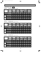
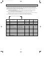
1) COOLING CAPACITY 50Hz
Service Ref.
PKH-2FKA3
PKH-2.5FKA2
PKH-2.5FKA3
PKH-3FKA2
PKH-3FKA3
PKH-4FKSA2
PKH-4FKSA3
Indoor
Intake
air
W.B.:
20
P.C.
CA
25
CA
P.C.
Outdoor intake air D.B.:
35
40
30
CA
P.C.
CA
P.C.
CA
P.C.
45
CA
P.C.
16
5,549 1.82 5,397 1.90 5,198 2.04 4,988 2.19 4,765 2.34 4,530 2.49
18
5,908 1.86 5,752 1.94 5,543 2.09 5,323 2.24 5,093 2.40 4,852 2.55
20
6,271 1.89 6,124 1.97 5,905 2.13 5,677 2.30 5,440 2.46 5,193 2.63
22
6,638 1.93 6,511 2.01 6,285 2.18 6,050 2.35 5,806 2.53 5,552 2.71
16
6,557 2.05 6,378 2.14 6,144 2.30 5,895 2.47 5,646 2.64 5,373 2.80
18
6,982 2.09 6,798 2.18 6,551 2.36 6,291 2.53 6,027 2.70 5,747 2.87
20
7,411 2.13 7,237 2.23 6,979 2.41 6,709 2.59 6,430 2.77 6,143 2.96
22
7,845 2.17 7,694 2.27 7,428 2.46 7,150 2.65 6,855 2.85 6,561 3.06
16
7,970 2.60 7,752 2.72 7,467 2.92 7,164 3.13 6,862 3.35 6,530 3.56
18
8,486 2.66 8,262 2.77 7,961 2.99 7,646 3.21 7,325 3.43 6,985 3.65
20
9,007 2.71 8,796 2.83 8,482 3.06 8,154 3.29 7,815 3.52 7,467 3.76
22
9,534 2.76 9,352 2.88 9,028 3.12 8,690 3.37 8,332 3.62 7,974 3.88
16
9,584 2.65 9,322 2.77 8,979 2.98 8,615 3.19 8,252 3.41 7,852 3.62
18
10,204 2.71 9,936 2.82 9,574 3.05 9,194 3.27 8,808 3.49 8,400 3.72
20
10,832 2.76 10,577 2.88 10,200 3.11 9,806 3.35 9,398 3.59 8,979 3.83
22
11,465 2.81 11,246 2.94 10,856 3.18 10,450 3.43 10,020 3.69 9,589 3.95
Note CA : Capacity (W)
P.C. : Power consumption (kW)
2) COOLING CAPACITY 60Hz
Service Ref.
PKH-2FKA3
PKH-2.5FKA2
PKH-2.5FKA3
PKH-3FKA2
PKH-3FKA3
PKH-4FKSA2
PKH-4FKSA3
Indoor
Intake
air
W.B.:
20
P.C.
CA
25
CA
P.C.
Outdoor intake air D.B.:
35
40
30
CA
P.C.
CA
P.C.
CA
P.C.
45
CA
50
P.C.
CA
P.C.
52
CA
P.C.
16
5,851 2.00 5,691 2.08 5,482 2.24 5,260 2.40 5,025 2.56 4,777 2.73 4,516 2.89 4,408 2.96
18
6,230 2.04 6,066 2.12 5,845 2.29 5,613 2.46 5,371 2.63 5,117 2.80 4,852 2.97 4,740 3.03
20
6,613 2.07 6,458 2.17 6,227 2.34 5,987 2.52 5,736 2.70 5,476 2.88 5,206 3.07 5,096 3.14
22
7,000 2.11 6,866 2.21 6,628 2.39 6,380 2.58 6,123 2.78 5,855 2.98 5,578 3.18 5,464 3.27
16
7,062 2.41 6,869 2.52 6,616 2.71 6,348 2.90 6,080 3.10 5,786 3.29 5,450 3.49 5,320 3.57
18
7,519 2.46 7,321 2.57 7,054 2.77 6,775 2.97 6,490 3.18 6,189 3.38 5,856 3.59 5,721 3.67
20
7,981 2.51 7,794 2.62 7,515 2.83 7,225 3.05 6.925 3.26 6,616 3.48 6,284 3.71 6,150 3.79
22
8,448 2.55 8,286 2.67 7,999 2.89 7,700 3.12 7,383 3.35 7,066 3.60 6,732 3.85 6,595 3.95
16
7,869 2.90 7,654 3.03 7,372 3.26 7,074 3.49 6,775 3.73 6,447 3.96 6,073 4.20 5,928 4.30
18
8,378 2.96 8,158 3.09 7,861 3.33 7,549 3.58 7,232 3.82 6,897 4.07 6,525 4.31 6,375 4.41
20
8,893 3.02 8,684 3.15 8,374 3.40 8,051 3.66 7,716 3.92 7,372 4.19 7,002 4.46 6,853 4.56
22
9,414 3.07 9,233 3.21 8,913 3.48 8,580 3.75 8,227 4.03 7,873 4.32 7,501 4.63 7,348 4.75
16
10,492 3.41 10,205 3.55 9,830 3.82 9,432 4.10 9,034 4.37 8,596 4.65 8,097 4.93 7,903 5.05
18
11,171 3.47 10,877 3.62 10,481 3.91 10,065 4.20 9,643 4.49 9,196 4.77 8,701 5.06 8,499 5.18
20
11,858 3.54 11,579 3.70 11,166 4.00 10,735 4.30 10,288 4.61 9,829 4.91 9,335 5.23 9,137 5.36
22
12,552 3.61 12,311 3.77 11,885 4.08 11,440 4.40 10,969 4.74 10,497 5.08 10,002 5.44 9,798 5.58
Cooling capacity correction factors
Service Ref.
PKH-2FKA3
PKH-2.5FKA2
PKH-2.5FKA3
PKH-3FKA2
PKH-3FKA3
PKH-4FKSA2
PKH-4FKSA3
Refrigerant piping length (one way)
25m
30m
35m
0.966
0.959
0.950
5m
1.00
10m
0.992
15m
0.983
20m
0.978
1.00
0.989
0.980
0.970
0.960
0.950
1.00
0.981
0.968
0.952
0.940
1.00
0.989
0.980
0.970
0.960
13
40m
0.945
45m
—
50m
—
0.940
0.930
0.920
0.910
0.925
0.913
0.900
0.886
0.874
0.950
0.940
0.930
0.920
0.910
OC132--1.qxp 1.11.8 10:42 AM Page 14
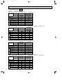
3) HEATING CAPACITY 50Hz
Service Ref.
PKH-2FKA3
PKH-2.5FKA2
PKH-2.5FKA3
PKH-3FKA2
PKH-3FKA3
PKH-4FKSA2
PKH-4FKSA3
Indoor
Intake
air
W.B.°C
15
20
25
15
20
25
15
20
25
15
20
25
-10
CA
4,280
4,098
3,939
4,931
4,721
4,537
6,232
5,967
5,735
7,328
7,016
6,743
P.C.
1.73
1.86
1.98
1.76
1.89
2.02
2.29
2.47
2.63
2.49
2.68
2.86
Outdoor intake air D.B.°C
0
5
CA
P.C.
CA
P.C.
5,591 1.90 6,336 2.09
5,380 2.05 6,100 2.25
5,167 2.19 5,874 2.41
6,441 1.93 7,229 2.12
6,198 2.09 7,027 2.29
5,952 2.23 6,767 2.45
8,141 2.52 9,225 2.77
7,834 2.72 8,881 2.99
7,523 2.91 8,553 3.20
9,572 2.74 10,847 3.01
9,211 2.95 10,443 3.24
8,845 3.16 10,056 3.47
P.C.
1.91
2.06
2.19
2.19
2.36
2.51
2.59
2.79
2.97
2.07
3.31
3.52
Outdoor intake air D.B.°C
0
5
CA
P.C.
CA
P.C.
5,904 2.10 6,691 2.31
5,681 2.26 6,441 2.48
5,456 2.42 6,203 2.66
7,157 2.41 8,110 2.64
6,887 2.60 7,808 2.85
6,613 2.77 7,519 3.05
8,498 2.85 9,631 3.13
8,178 3.07 9,272 3.37
7,853 3.28 8,928 3.61
10,914 3.38 12,368 3.71
10,502 3.64 11,907 4.00
10,085 3.89 11,466 4.28
Refrigerant piping length (one way)
25m
30m
35m
1.00
1.00
0.998
-5
P.C.
1.56
1.68
1.79
1.59
1.71
1.82
2.07
2.23
2.37
2.25
2.43
2.58
CA
4,905
4,713
4,521
5,651
5,429
5,209
7,142
6,862
6,583
8,398
8,068
7,741
10
CA
7,139
6,871
6,643
8,225
7,916
7,653
10,395
10,004
9,672
12,223
11,763
11,373
P.C.
2.28
2.46
2.64
2.32
2.50
2.68
3.03
3.26
3.50
3.29
3.54
3.80
15
CA
8,000
7,693
7,473
9,216
8,863
8,609
11,648
11,201
10,881
13,696
13,171
12,794
P.C.
2.49
2.68
2.87
2.53
2.73
2.92
3.30
3.56
3.82
3.59
3.86
4.14
Note CA : Capacity (W)
P.C. : Power consumption (kW)
4) HEATING CAPACITY 60Hz
Service Ref.
PKH-2FKA3
PKH-2.5FKA2
PKH-2.5FKA3
PKH-3FKA2
PKH-3FKA3
PKH-4FKSA2
PKH-4FKSA3
Indoor
Intake
air
W.B.°C
15
20
25
15
20
25
15
20
25
15
20
25
-10
CA
4,520
4,328
4,159
5,479
5,246
5,041
6,506
6,229
5,987
8,355
8,000
7,688
-5
P.C.
1.73
1.86
1.97
1.98
2.13
2.26
2.34
2.52
2.68
2.78
2.99
3.18
CA
5,180
4,977
4,775
6,279
6,032
5,787
7,456
7,163
6,873
9,575
9,199
8,826
10
CA
7,539
7,256
7,015
9,138
8,795
8,503
10,852
10,444
10,097
13,936
13,412
12,967
15
P.C.
2.52
2.72
2.91
2.89
3.11
3.34
3.42
3.68
3.95
4.06
4.37
4.69
CA
8,448
8,124
7,891
10,240
9,847
9,565
12,160
11,694
11,359
15,616
15,017
14,587
P.C.
2.75
2.96
3.18
3.15
3.39
3.64
3.73
4.01
4.31
4.42
4.76
5.11
Note CA : Capacity (W)
P.C. : Power consumption (kW)
Heating capacity correction factors
Service Ref.
PKH-2FKA3
PKH-2.5FKA2
PKH-2.5FKA3
PKH-3FKA2
PKH-3FKA3
PKH-4FKSA2
PKH-4FKSA3
5m
1.00
10m
1.00
15m
1.00
20m
1.00
1.00
1.00
1.00
1.00
1.00
1.00
1.00
1.00
1.00
1.00
1.00
1.00
1.00
1.00
1.00
1.00
14
40m
0.995
45m
—
50m
—
0.998
0.995
0.993
0.990
1.00
0.998
0.995
0.993
0.990
1.00
0.998
0.995
0.993
0.990
OC132--1.qxp 1.11.8 10:42 AM Page 15
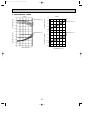
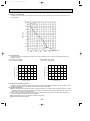
2. PERFORMANCE CURVE
Cooling
Heating
INDOOR W.B.(:)
1.2
1.0
22
20
18
16
0.8
0.6
TOTAL INPUT (RATIO)
15
20
25
1.2
INDOOR D.B. (:)
1.0
0.8
0.6
1.4
22
20
18
16
1.2
INDOOR W.B.(:)
1.0
0.8
0.6
0.4
-5
CAPACITY (RATIO)
1.4
TOTAL INPUT (RATIO)
CAPACITY (RATIO)
1.4
5
1.4
INDOOR D.B. (:)
1.2
25
20
15
1.0
0.8
0.6
0.4
-12-10
15
25 35 46
OUTDOOR D.B.(:)
15
-5
0
5
10 15
OUTDOOR W.B. (:)
OC132--1.qxp 1.11.8 10:42 AM Page 16
3. ELECTRICAL DATA 50Hz
Indoor unit · · · · · 220V 50Hz 1phase
Outdoor unit · · · 220V 50Hz 1phase / 380V 50Hz 3phase
Indoor unit
PKH-2FKA3
PKH-2.5FKA2
PKH-2.5FKA3
Outdoor unit
PUH-2VKA2
PUH-2VKA3
PUH-2.5VKA2
PUH-2.5VKA3
Service Ref.
Mode
Cool
Capacity(W)
5,400 6,150
Total Input(kW)
Cool
Heat
PUH-4YKSA3
PUH-4YKSA4
Heat
PUH-3YKA2
PUH-3YKA3
PUH-3YKA4
Cool Heat
7,800 9,000
7,800 9,000
9,400 10,500
PUH-3VKA2
PUH-3VKA3
Cool
Cool
Heat
2.19
2.21
2.51
3.02
3.28
3.27
Indoor
unit
6,400 7,100
PKH-4FKSA2
PKH-4FKSA3
Input(kW)
0.07
0.07
0.095 0.095
0.095 0.095
0.095 0.095
0.11
0.114
Current(A)
0.32
0.32
0.440 0.440
0.440 0.440
0.440 0.440
0.530
0.530
Starting current(A)
0.40
0.40
0.70
0.70
0.70
0.70
0.70
0.70
0.80
0.80
Outdoor
unit
Heat
PKH-3FKA2
PKH-3FKA3
Input(kW)
2.12
2.14
2.41
2.16
3.13
2.92
3.13
2.92
3.17
3.16
Current(A)
9.83
9.93
11.18
10.02
14.67 13.68
5.23
4.88
5.29
5.28
43
43
52
52
34
34
37
37
Starting current(A)
2.26
3.23
54
3.02
54
3.23
Indoor unit · · · · · 230V 50Hz 1phase
Outdoor unit· · · · 230V 50Hz 1phase / 400V 50Hz 3phase
Indoor unit
PKH-2FKA3
PKH-2.5FKA2
PKH-2.5FKA3
Outdoor unit
PUH-2VKA2
PUH-2VKA3
PUH-2.5VKA2
PUH-2.5VKA3
Service Ref.
Mode
Cool
Capacity(W)
5,450 6,200
Total Input(kW)
Heat
2.30
PUH-4YKSA3
PUH-4YKSA4
Heat
PUH-3YKA2
PUH-3YKA3
PUH-3YKA4
Cool Heat
7,850 9,050
7,850 9,050
9,450 10,600
PUH-3VKA2
PUH-3VKA3
Cool
3.03
Cool
Heat
3.03
3.30
3.29
Indoor
unit
2.25
Cool
6,450 7,150
PKH-4FKSA2
PKH-4FKSA3
Input(kW)
0.070 0.070
0.095 0.095
0.095 0.095
0.095 0.095
0.114
0.114
Current(A)
0.320 0.320
0.440 0.440
0.440 0.440
0.440 0.440
0.530
0.530
Starting current(A)
0.40
0.40
0.80
0.80
0.80
0.80
0.80
0.80
0.90
0.90
Outdoor
unit
2.23
Heat
PKH-3FKA2
PKH-3FKA3
Input(kW)
2.16
2.18
2.44
2.20
3.14
2.93
3.14
2.93
3.19
3.18
Current(A)
9.78
9.87
10.94
9.86
14.22 13.27
5.21
4.86
5.23
5.22
44
44
52
52
36
36
39
39
Starting current(A)
2.54
3.24
56
56
3.24
Indoor unit · · · · · 240V 50Hz 1phase
Outdoor unit· · · · 240V 50Hz 1phase / 415V 50Hz 3phase
Indoor unit
PKH-2FKA3
PKH-2.5FKA2
PKH-2.5FKA3
Outdoor unit
PUH-2VKA2
PUH-2VKA3
PUH-2.5VKA2
PUH-2.5VKA3
Service Ref.
Mode
Cool
Capacity(W)
5,500 6,250
2.29
Heat
2.33
PUH-4YKSA3
PUH-4YKSA4
Heat
PUH-3YKA2
PUH-3YKA3
PUH-3YKA4
Cool Heat
7,900 9,100
7,900 9,100
9,500 10,700
PUH-3VKA2
PUH-3VKA3
Cool
3.04
Cool
Heat
3.04
3.31
3.30
Indoor
unit
2.27
Cool
6,500 7,200
PKH-4FKSA2
PKH-4FKSA3
Input(kW)
0.070 0.070
0.095 0.095
0.095 0.095
0.095 0.095
0.114
0.11
Current(A)
0.320 0.320
0.440 0.440
0.440 0.440
0.440 0.440
0.530
0.53
Starting current(A)
0.40
0.40
0.80
0.80
0.80
0.80
0.80
0.80
0.90
0.90
Outdoor
unit
Total Input(kW)
Heat
PKH-3FKA2
PKH-3FKA3
Input(kW)
2.20
2.22
2.46
2.23
3.15
2.94
3.15
2.94
3.20
3.19
Current(A)
9.86
9.95
10.68
9.78
13.82 12.89
5.16
4.81
5.24
5.22
45
45
52
52
37
37
40
40
Starting current(A)
2.56
3.25
58
16
58
3.25
OC132--1.qxp 1.11.8 10:42 AM Page 17
3. ELECTRICAL DATA 60Hz
Indoor unit · · · · · 220V 60Hz 1phase
Outdoor unit · · · 220V 60Hz 1phase/3phases
Rating condition (Cooling)...Indoor D.B. 27:, W.B. 19: Outdoor D.B. 35:
PKH-2.5FKA2
PKH-2FKA3
Indoor unit
PKH-2.5FKA3
Service Ref.
PUH-2NKA1
PUH-2.5NKA1
Outdoor unit
PUH-2NKA2
PUH-2.5NKA2
Outdoor
unit
Indoor
unit
Mode
Capacity (W)
Total Input (kW)
Input (kW)
Current (A)
Starting current (A)
Input (kW)
Current (A)
Starting current (A)
Cooling
5,800
2.49
0.08
0.37
0.50
2.41
11.07
54
Cooling
7,000
3.01
0.095
0.44
0.70
2.91
13.50
58
Rating condition (Cooling)...Indoor D.B. 29:, W.B. 19: Outdoor D.B. 46:, W.B. 24: (SSA385, 386)
Rating condition (Heating)...Indoor D.B. 21:
Outdoor D.B. 7:, W.B. 6:
PKH-2.5FKA
2
PKH-2FKA3
Indoor unit
PKH-2.5FKA3
Service Ref.
PUH-2NKA1
PUH-2.5NKA1
Outdoor unit
PUH-2NKA2
PUH-2.5NKA2
}
Outdoor
unit
Indoor
unit
Mode
Capacity (W)
Total Input (kW)
Input (kW)
Current (A)
Starting current (A)
Input (kW)
Current (A)
Starting current (A)
Cooling
5,100
2.91
0.08
0.37
0.50
2.83
12.99
54
Heating
6,600
2.53
0.08
0.37
1.50
2.45
11.2
54
Cooling
5,900
3.53
0.095
0.44
0.70
3.43
15.75
58
Heating
8,000
2.90
0.095
0.44
0.70
2.80
13.0
58
Rating condition (Cooling)...Indoor D.B. 27:, W.B. 19: Outdoor D.B. 35:
PKH-3FKA2
PKH-4FKSA2
Indoor unit
PKH-3FKA3
PKH-4FKSA3
Service Ref.
PUH-3NKA
1
Outdoor unit
PUH-4TKSA1
PUH-3NKA2
Outdoor
unit
Indoor
unit
Mode
Capacity (W)
Total Input (kW)
Input (kW)
Current (A)
Starting current (A)
Input (kW)
Current (A)
Starting current (A)
Cooling
7,800
3.62
0.095
0.44
0.70
3.52
16.49
80
Cooling
10,400
4.25
0.114
0.53
0.80
4.14
11.81
69
Rating condition (Cooling)...Indoor D.B. 29:, 19: W.B. Outdoor D.B. 46:, W.B. 24:
Rating condition (Heating)...Indoor D.B. 21:
Outdoor D.B. 7:, W.B. 6:
PKH-4FKSA2
PKH-3FKA2
Indoor unit
PKH-3FKA3
PKH-4FKSA3
Service Ref.
PUH-3NKA1
Outdoor unit
PUH-4TKSA
1
PUH-3NKA2
Outdoor
unit
Indoor
unit
Mode
Capacity (W)
Total Input (kW)
Input (kW)
Current (A)
Starting current (A)
Input (kW)
Current (A)
Starting current (A)
Cooling
6,900
4.23
0.095
0.44
0.70
4.13
18.77
80
Heating
9,500
3.43
0.095
0.44
0.70
3.33
15.6
80
Cooling
9,400
5.12
0.114
0.53
0.80
5.01
14.14
69
Heating
12,200
4.07
0.114
0.53
0.80
3.96
11.3
69
17
}
(SSA385, 386)
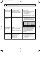
OC132--1.qxp 1.11.8 10:42 AM Page 18
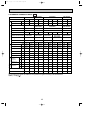
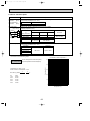
4. STANDARD OPERATION DATA 50Hz
Service Ref.
PKH-2FKA3
Total
Mode
Electrical circuit
Heating
Cooling
Heating
Cooling
Heating
Cooling
Heating
Cooling
Heating
6,500
7,200
7,900
9,100
7,900
9,100
9,500
10,700
2.56
2.33
3.25
3.04
3.25
3.04
3.31
3.30
W
5,500
6,250
Input
kW
2.27
2.29
PKH-2FKA3
PKH-2.5FKA2
PKH-2.5FKA3
PKH-3FKA2
PKH-3FKA3
PKH-4FKSA2
PKH-4FKSA3
Phase,Hz
1,50
1,50
1,50
1,50
Volts
240
240
240
240
Amperes
0.320
0.320
0.440
0.440
0.440
0.440
0.440
0.440
0.530
0.530
PUH-2VKA2
PUH-2VKA3
PUH-2.5VKA2
PUH-2.5VKA3
PUH-3VKA2
PUH-3VKA3
PUH-3YKA2
PUH-3YKA3
PUH-3YKA4
Phase,Hz
1,50
1,50
1,50
3,50
3,50
Volts
240
240
240
415
415
Outdoor unit Service Ref.
Amperes
9.86
Discharge pressure
Refrigetrant circuit
PKH-4FKSA2
PKH-4FKSA3
Cooling
Capacity
Indoor unit Service Ref.
Suction pressure
MPa 1.87
(kg/cm2) (19.1)
MPa 0.42
(kg/cm2) (4.28)
PUH-4YKSA3
PUH-4YKSA4
9.95
10.68
9.78
13.82
12.89
5.16
4.81
5.24
5.22
1.99
(20.3)
0.36
(3.67)
2.00
(20.4)
0.52
(5.3)
1.62
(16.5)
0.36
(3.67)
2.07
(21.1)
0.45
(4.59)
1.96
(20.0)
0.37
(37.7)
2.07
(21.1)
0.45
(4.59)
1.96
(20.0)
0.35
(3.57)
1.80
(18.4)
0.51
(5.2)
1.69
(17.2)
0.37
(37.7)
Discahrge temperature
˚C
86
90
85
74
90
86
90
86
79
76
Condensing temperature
˚C
51
53
53
44
53
52
53
52
49
46
Suction temperature
˚C
2
-2
7
-3
6
-2
6
-2
8
-1
m
5
5
5
5
5
5
5
5
5
5
D.B. ˚C
27
20
27
20
27
20
27
20
27
20
W.B. ˚C
19
15
19
15
19
15
19
15
19
15
D.B. ˚C
13.0
44.3
14.5
37.9
13.2
43.4
13.2
43.4
14.3
40.4
D.B. ˚C
35
7
35
7
35
7
35
7
35
7
W.B. ˚C
24
6
24
6
24
6
24
6
24
6
SHF
0.71
-
0.83
-
0.74
-
0.74
-
0.80
-
BF
0.15
-
0.11
-
0.12
-
0.12
-
0.11
-
Ref.pipe length
Outdoor
Indoor side
side
PKH-3FKA2
PKH-3FKA3
PKH-2.5FKA2
PKH-2.5FKA3
Intake air
temperature
Discharge air
temperature
Intake air
temperature
The unit of pressure has been changed to MPa on the international system of unit (SI unit system).
The converted score against the traditional unit system can be gotten according to the formula below.
F)
1(MPa) = 10.2(kg/F
18
OC132--1.qxp 1.11.8 10:42 AM Page 19
4. STANDARD OPERATION DATA 60Hz
Electrical circuit
Total
Mode
Capacity
Input
Indoor unit Service Ref.
Phase, Hz
Volts
Amperes
W
KW
V
A
Outdoor unit Service Ref.
Refrigerant circuit
Phase, Hz
Volts
Amperes
Outdoor Indoor side
side
PKH-2.5FKA2
PKH-2.5FKA3
PKH-3FKA2
PKH-3FKA3
PKH-4FKSA2
PKH-4FKSA3
PKH-2FKA3
Cooling Heating
7,000
8,000
3.01
2.90
PKH-2.5FKA2
PKH-2.5FKA3
Cooling Heating
7,800
9,500
3.62
3.43
PKH-3FKA2
PKH-3FKA3
Cooling Heating
10,400
12,200
4.25
4.07
PKH-4FKSA2
PKH-4FKSA3
1.60
220
1.60
220
1.60
220
1.60
220
0.37
PUH-2NKA1
PUH-2NKA2
0.44
0.44
PUH-2.5NKA1
PUH-2.5NKA2
0.44
0.44
PUH-3NKA1
PUH-3NKA2
1.60
220
1.60
220
1.60
220
PKH-2FKA3
Service Ref.
V
A
Mpa
Discharge pressure
(kgf/f)
Mpa
Suction pressure
(kgf/f)
Discharge temperature
˚C
Condensing temperature
˚C
Suction temperature
˚C
Ref. pipe length
m
D.B. ˚C
Intake air temperature
W.B. ˚C
Discharge air temperature D.B. ˚C
D.B. ˚C
Intake air temperature
W.B. ˚C
SHF
BF
Cooling
5,800
2.49
Heating
6,600
2.53
0.37
11.07
1.98
(20.2)
0.41
(4.2)
70.2
51.8
2.4
5
27
19
13
35
24
0.70
0.19
11.2
2.05
(21.0)
0.34
(3.5)
98.3
53.7
-3.0
5
21
15.5
45.7
7
6
—
—
13.50
2.12
(21.6)
0.52
(5.3)
78.3
54.2
5.8
5
27
19
14
35
24
0.79
0.11
13.0
1.82
(18.6)
0.36
(3.7)
82.9
48.0
-3.4
5
21
15.5
40.2
7
6
—
—
16.49
2.07
(21.1)
0.45
(4.6)
76.1
56.7
4.6
5
27
19
13.1
35
24
0.74
0.11
0.53
0.53
PUH-4TKSA1
3.60
220
15.6
2.02
(20.6)
0.34
(3.5)
83.7
52.2
-2.9
5
21
15.5
44.0
7
6
—
—
11.81
1.97
(20.1)
0.46
(4.7)
81.6
51.1
5.1
5
27
19
13.5
35
24
0.76
0.11
11.30
1.90
(19.4)
0.35
(3.6)
87.1
50.2
-2.9
5
21
15.5
43.5
7
6
—
—
The unit of pressure has been changed to Mpa based on the international SI system.
F)
The conversion factor is : 1(MPa)=10.2(kgf/F
5. OUTLET AIR SPEED AND COVERAGE RANGE
Service Ref.
PKH-2FKA3
PKH-2.5FKA2
PKH-2.5FKA3
PKH-3FKA2
PKH-3FKA3
PKH-4FKSA2
PKH-4FKSA3
Air flow
K/min
13
20
20
28
Air speed
m/sec.
4.0
4.9
4.9
5.4
m
9.1
12.4
12.4
15.3
Coverage range
The air coverage range is the value up to the position where the air speed is 0.25m/sec. when air is blown out horizontally
from the unit at the Hi notch position.
The coverage range should be used only as a general guideline since it varies according to the size of the room and the furniture inside the room.
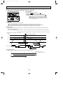
19
Front
(Height ut unit)
68- 5
hole
53
476
450
405
Gas pipe position
Liquid pipe position
2 X5 - 2.9 hole
for tapping screw
Knock out hole for
left-rear piping
45
85
80
5
2.
323
276
229
R5
179
150
330
R
35
150 or more
190
60
(100 for left-hand
side piping)
Ref.pipes & drain pipe
60
1250
215
Knock out hole for
left-hand side piping
(Width of unit)
5
625
Tapping screw
277
300
0
24
0
Sleeve Through hole
90
90~ 100
Details of installation plate
1 Sleeves are available on
the market.
2 This size shows the lower
end of through hole.
2-unit hangers Unit cennter
50 or more
Service space required
around indoor unit
Gas pipe
Drain pipe
Lequid pipe
70
52
.
70
73
(375)
Knock out hole for
left-rear piping
447
(178)
300
286X 2
227
2
Gas pipe
1 Liquid pipe
Drainage
50
2 tapping screws
for installation plate
0
35
53
80
130
177
Rear piping hole
13- 14
hole
(Necessary clearance for
Unit installation)
130 or less
Right side
Left side
625
47
70
3/8F
5/8F
2
1
976
479 Air outlet
Knock out hole
for piping
Drainage(Flexible hole: length 1200)
1100
685
635
Terminal block & pipe position
Lower side
500
(manual)
236
227
553
A
26
190
200
60
Installation bolt position
Right side
15 or less
bolt
A
B
Knock out hole
for piping
70
20
8
Knock out hole for under-piping
(2:1)
60
8
Knock-out hole for
night-hand side piping
(2:1)
Knock out hole for right piping
B
Knock out hole for piping
Terminal block for control
170
200
Right side
Terminal block
Air intake
Terminal block for
power supply
222
143
173
223
Service panel for
power supply connection
449 Air intake
Auto vanes
Lower side
48
16 -louvers
479 Air outlet
449 Air intake
168
1250
91
968 Air intake
213
4
Pipe position
Left side
150
174
224
8
80
271
20
25
318
65
30 or more
180 or more
374
405
450
476
486
20
9
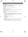
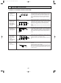
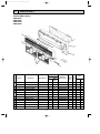
1. INDOOR UNIT
PKH-2FKA3
8
70
5
Front
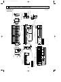
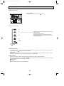
OC132--1.qxp 1.11.8 10:42 AM Page 20
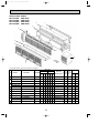
OUTLINES AND DIMENSIONS
Unit : mm
100
4 39
32-ø12 hole for bolt
66-ø6 hole for
tapping screw
Wall fixture
37
74
A
30
225
18
39
990
180
12-ø6 hole for
tapping screw
240
on left-hand side
C
30
455
39
610
91
314
285
19
245
90
25
Drain hose for
left-hand side piping
Knock out hole for
left piping
Left side
Range for left rear piping opening
280
Drainage range
on right-hand side
37
74
Unit center
10 91=(910)
900
18 Drainage range
98 32
B
37
65
Knock out hole for piping
A
100
4
340
30
10
184
30
30
80
29
280
21
45
45
Front
235
552 Air outlet
Liquid pipe
235
62.5
13
Refrigerant pipe. Drain pipe
Change vane (manual)
Under panel
Removable at left-hand
side piping
Knock out hole for under-piping
1120
Auto vane
Lower side
1110
45
Drain hose
1400
1090 Air intake
235
552 Air outlet
235
Rear piping opening
60
183
240
235
Right side
Terminal block for control
197
B
Drain hose
Bolt
Terminal block for power supply
Gas pipe
Terminal block for remote controller
15 and less
C
Knock out hole for right piping
Refrigerant pipe. Drain pipe
Liquid pipe 9.52(3/8F)
Gas pipe 15.88(5/8F)
(Liquid pipe)
55 (Gas pipe) 107
120
111
42
PKH-2.5FKA2 PKH-3FKA2
PKH-2.5FKA3 PKH-3FKA3
58
Top
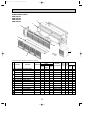
OC132--1.qxp 1.11.8 10:42 AM Page 21
Unit : mm
295
225
39
180
314
285
19
245
90
Range for left rear piping opening
280
750
Drainage range
91
on right-hand side
595
12-ø6 hole for tapping screw
240
25
Knock out hole for left piping
340
Drain hose for left-hand side piping
37
74
C
30
13 91=(1183)
900
Drainage range
on left-hand side
18
Range for left rear piping opening
41-ø12 hole for bolt
18
1270
Unit center
98 65
Wall fixture
39
B
37
65
Knock out hole for wiring
Unit out line
37
74
A
30
84-ø6 hole for
tapping screw
100
4 39
A
100
4
Left side
235
10
184
30
30
80
29
280
30
22
Auto vane
45
1680
Front
235
Drain hose
235
183
694 Air outlet
Refrigerant pipe. Drain pipe
235
Right side
240
(Liquid pipe)
B
55 (Gas pipe) 102
120
111
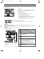
Gas pipe 19.05(3/4F)
Liquid pipe 9.52(3/8F)
Bolt
C
Terminal block for power supply
Gas pipe
Terminal block for control 15 and less
Under panel
(Removable at left-hand side piping)
Knock out hole for under-piping
197
Terminal block for remote controller
Change vane (manual)
Lower side
1400
45
62.5
13
Knock out hole for right piping
235
Liquid pipe
1370 Air intake
45
1110 Drain hose
235
694 Air outlet
45
Rear piping opening
60
42
PKH-4FKSA2
PKH-4FKSA3
58
Top
OC132--1.qxp 1.11.8 10:42 AM Page 22
Unit : mm
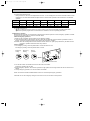
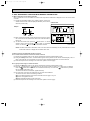
OC132--1.qxp 1.11.8 10:42 AM Page 23
Unit : mm(inch)
2. REMOTE CONTROLLER
FILTER
FILTER
CHECK
CHECK MODE
TEST RUN
TEST RUN
120
CHECK MODE
18
130
Rear side wiring arrangement opening.
83.5
CHECK
46
CAUTION
SW18
SW17
23
OC132--1.qxp 1.11.8 10:42 AM Page 24
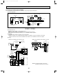
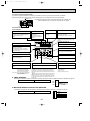
6
WIRING DIAGRAM
PKH-2FKA3
POWER SUPPLY
~(1 PHASE)
AC220-240V 50Hz
AC220V 60Hz
L
N
WHT
LS
RED
MF
GRN/YLW
11.1VAC
220V
TB2
230V
C
14.2VAC
NAME
FAN MOTOR CAPACITOR
PROGRAM TIMER CONNECTOR
REMOTE SWITCH CONNECTOR
LOSSNAY CONNECTOR
CENTRALLY CONTROL CONNECTOR
EMERGENCY OPERATION CONNECTOR
FUSE (6.3A 250V)
INDOOR CONTROLLER BOARD
DC 12V POWER LED
DC 5V POWER LED
LIMIT SWITCH
FAN MOTOR
VANE MOTOR
REMOTE CONTROLLER BOARD
ROOM TEMPERATURE THERMISTOR
(0°C/15KΩ. 25°C/5.4KΩ DETECT)
BRN
2 1
1 2 3 4 5 6 7 8 9 10
SYMBOL
RT2
SW1<I.B>
SW2<I.B>
SW3<I.B>
SW5.6<I.B>
SW7<I.B>
SW17<R.B>
SW18<R.B>
T
TB2
TB4
TB5.6
X4<I.B>
ZNR
R.B
SW18
OFF
ON
4321
SW17
VANE
1234
INTAKE
CN23
1234
2 1
123456
RT1
CN2L
SW1
3 TB4
TO OUTDOOR UNIT
2
CONNECTING WIRES
1
DC12V
CN20
LOSSNAY
RT1
CN51
SW6
BRN
ORN
YLW
RT2
PIPE
CN24
SW5
TRANSMISSION WIRES
2 TB5 DC12V
1
CN21
HEATER
SW2
ON
OFF
SYMBOL
CENTRALLY
CONTROL
12
BLU
BLU
2 1
SW3
ON
OFF
1 3 5
123
C
CN1<R.B>
CN2<R.B>
CN2L<I.B>
CN51<I.B>
FAN2
F1<I.B>
I.B
LED1<I.B>
LED2<I.B>
LS
MF
MV
R.B
CN30
ZNR
SW7
FAN2
CN22
LED1 12V
POWER
4 3 2 1
CN40
REMOCON
POWER
X4
X4
RED
BRN
LED2 5V
POWER
F1
VANE
4 3 2 1 CN4T
TRANS
1 3 CNT
TRANS
TO
OUTDOOR
REMOCON
CN6V
RED
WHT
YLW
RED
BLU
CND 1 3
POWER
3 2 1
1 3
1 3 5
2 1
FAN1
240V
T
RED
WHT
BLK
I.B
YLW
RED
ORN
MV
OFF
ON
87654321
TB6
A01 B02
CN1
5 4 3 2 1
CN2
3 2 1
NAME
PIPE TEMPERATURE THERMISTOR
(0°C/15KΩ. 25°C/5.4KΩ DETECT)
MODE SELECTOR
ADDRESS SELECTOR
EMERGENCY OPERATION SWITCH
MODEL SELECTOR
MODEL SELECTOR
ADDRESS SELECTOR
FUNCTION SELECTOR
TRANSFORMER
POWER SUPPLY TERMINAL BLOCK
INDOOR/OUTDOOR CONNECTING WIRE TERMINAL BLOCK
REMOTE CONTROLLER TRANSMISSION LINE TERMINAL BLOCK
FAN MOTOR RELAY
VARISTOR
NOTES:
1. Since the indoor fan motor (MF) is connected with 230, 240V power, using 220V power will require a setting change of the dip switch (SW7<I.B>) on the indoor
controller board as shown in fig : w 1.
ON
ON
fig w1 Indoor fan motor (MF) for 220V.
SW5
OFF
OFF
1234
1234
2. Since the indoor transformer (T) is connected with 240V power, if 220,230V power is used. Change the wiring connection showing fig : w 2.
fig w2 When power supply is
240V YELLOW
230V ORANGE
230V
220V RED
220V
3.
4.
5.
6.
Since the outdoor side electric wiring may change be sure to check the outdoor unit electric wiring for servicing.
Indoor and outdoor connecting wires are made with polarities, make wiring matching terminal numbers.
Symbols used in wiring diagram above are,
: Connector.
: Terminal block.
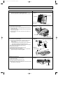
Emergency operation
If remote controller of microcomputer fails but there is no other trouble, emergency operation is possible by setting dip switch (SW3<I.B>) on the indoor controller board.
[Check items]
(1) Make sure that no other trouble exist the outdoor unit. Trouble with the outdoor unit prevents emergency operation.
(If any trouble exists the outdoor unit error code “P8” will be displayed on the remote controller and the trouble position will be shown on the outdoor controller
board LED. See electric wiring diagram of the outdoor unit for details.)
(2)Make sure that there is no trouble with the indoor fan.
Emergency operation will be continuous operation mode due to power ON/OFF(ON/OFF with the remote controller is not possible).
[Emergency operation procedure]
(1)Set the dip switch (SW3<I.B>) on the indoor controller board to 1 on and 2 off for cooling and 1 - 2 on for heating.
(2)Turn on outdoor unit side circuit breaker, then indoor unit side circuit breaker.
In this order.
(3)During emergency operation indoor fan runs at high speed but automatic vane remains stop.
(4)Thermostat will not function. Cold air blows out for defrosting during heating thus do not operate defrosting for along time.
(5)Emergency cooling should be limited to 10 hours maximum.
(The indoor unit heat exchanger may freeze).
(6)After each operation, and set all dip switches (SW3<I.B>) to OFF.
BG79N618H01
24
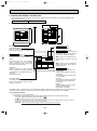
OC132--1.qxp 1.11.8 10:42 AM Page 25
PKH-2.5FKA2 PKH-3FKA2 PKH-4FKSA2
PKH-2.5FKA3 PKH-3FKA3 PKH-4FKSA3
L
N
POWER SUPPLY
~ (1 PHASE)
AC220-240V 50Hz
AC220V 60Hz
GRN/YLW
10VAC
240V
MF
TB2
C
FAN1
220V
14.3VAC
1 3 CNT
TRANS
POWER
1
BRN
RED
BRN
SYMBOL
TB4
3
2
1
RT1
4FKSA
ON
OFF
1 2 3 4
TRANSMISSION WIRES
DC12V
TO OUTDOOR UNIT
CONNECTING WIRES
DC12V
R.B
SW18
OFF
ON
4321
SW17
CN2L
NAME
FAN MOTOR CAPACITOR
PROGRAM TIMER CONNECTOR
REMOTE SWITCH CONNECTOR
LOSSNAY CONNECTOR
DRAIN LIFT-UP MECHANISM CONNECTOR
CENTRALLY CONTROL CONNECTOR
FUSE (6.3A 250V)
INDOOR CONTROLLER BOARD
MODE SELECTOR JUMPER RESISTOR
MODE SELECTOR JUMPER RESISTOR
MODE SELECTOR JUMPER RESISTOR
DC 12V POWER LED
DC 5V POWER LED
FAN MOTOR
VANE MOTOR
REMOTE CONTROLLER BOARD
2
1
RT2
LOSSNAY
4 5 6 7 8 9 10
BRN
ORN
YLW
TB5
2 1
1234
BLU
BLU
2 1
2
INTAKE
CN30
4
4 3 2 1
SYMBOL
C
CN1<R.B>
CN2<R.B>
CN2L<I.B>
CN27<I.B>
CN51<I.B>
F1, 2 <I.B>
I.B
J1
J5
J9
LED1<I.B>
LED2<I.B>
MF
MV
R.B
2
PIPE
5 4 3 2 1
CN24
123456
DRAIN
J1
SW6
CN50
J9
HEATER
J5
ON
OFF
CN21
CN20
12
1234
SW2
CN40
CN27
D.U.M
ON
OFF
CN51
LED1 12V
SW3 POWER
SW7
REMOCON
POWER
ZNR
CENTRALLY
CONTROL
X4
2.5,3FKA
ON
OFF
1 2 3 4
3 2 1
VANE
LED2 5V
POWER
SW7
2 1
CN6V
F1
MV
4 3 2 1 CN4T
TRANS
CN22
F2
6
TO
OUTDOOR
REMOCON
X4
RED
WHT
YLW
RED
BLU
CND 1 3
1 3 5
MODELS
6
T
RED
WHT
BLK
I.B
RED
YLW
ORN
230V
OFF
ON
87654321
TB6
A01 B02
CN1
5 4 3 2 1
CN2
3 2 1
NAME
RT1
ROOM TEMPERATURE THERMISTOR
(0°C/15KO. 25°C/5.4KO DETECT)
RT2
PIPE TEMPERATURE THERMISTOR
(0°C/15KO. 25°C/5.4KO DETECT)
ADDRESS SELECTOR
EMERGENCY OPERATION SWITCH
MODEL SELECTOR
MODEL SELECTOR
ADDRESS SELECTOR
FUNCTION SELECTOR
TRANSFORMER
POWER SUPPLY TERMINAL BLOCK
INDOOR/OUTDOOR CONNECTING WIRE TERMINAL BLOCK
REMOTE CONTROLLER
TRANSMISSION LINE TERMINAL BLOCK
FAN MOTOR RELAY
VARISTOR
SW2<I.B>
SW3<I.B>
SW6<I.B>
SW7<I.B>
SW17<R.B>
SW18<R.B>
T
TB2
TB4
TB5.6
X4<I.B>
ZNR
NOTES:
1. Since the indoor fan motor (MF) is connected with 230, 240V power, using 220V power will require a setting change of the dip switch (SW7<I.B>) on the indoor
controller board as shown in fig : w 1.
ON
ON
fig w1 Indoor fan motor (MF) for 220V.
SW7
OFF
OFF
1234
1234
2. Since the indoor transformer (T) is connected with 240V power, if 220,230V power is used. Change the wiring connection showing fig : w 2.
w
fig 2 When power supply is
240V YELLOW
230V ORANGE
230V
220V RED
220V
3. Since the outdoor side electric wiring may change be sure to check the outdoor unit electric wiring for servicing.
4. Indoor and outdoor connecting wires are made with polarities, make wiring matching terminal numbers.
5. Symbols used in wiring diagram above are,
: Connector.
: Terminal block.
6. Emergency operation
If remote controller or microcomputer fails but there is no other trouble, emergency operation is possible by setting dip switch (SW3<I.B>) on the indoor controller board.
[Check items]
(1) Make sure that no other trouble exist the outdoor unit. Trouble with the outdoor unit prevents emergency operation.
(If any trouble exists the outdoor unit error code “P8” will be displayed on the remote controller and the trouble position will be shown on the outdoor controller
board LED. See electric wiring diagram of the outdoor unit for details.)
(2)Make sure that there is no trouble with the indoor fan.
Emergency operation will be continuous operation mode due to power ON/OFF(ON/OFF with the remote controller is not possible).
[Emergency operation procedure]
(1)Set the dip switch (SW3<I.B>) on the indoor controller board to 1 on and 2 off for cooling and 1 - 2 on for heating.
(2)Turn on outdoor unit side circuit breaker, then indoor unit side circuit breaker.
In this order.
(3)During emergency operation indoor fan runs at high speed but automatic vane remains stop.
(4)Thermostat will not function. Cold air blows out for defrosting during heating thus do not operate defrosting for along time.
(5)Emergency cooling should be limited to 10 hours maximum.
(The indoor unit heat exchanger may freeze).
(6)After each operation, set all dip switches (SW3<I.B>) to OFF.
BG79N621H01
25
OC132--1.qxp 1.11.8 10:42 AM Page 26
7
REFRIGERANT SYSTEM DIAGRAM
PKH-2FKA3
PKH-2.5FKA2 ,
PKH-3FKA2 ,
/
/
/
/
PKH-2.5FKA3
PKH-3FKA3
PUH-2VKA2 ,
PUH-2.5VKA2 ,
PUH-3VKA2 ,
PUH-3YKA2 ,
High pressure
control switch
Oil separator
Refrigerant pipe
(option)
15.88mm( 5/8")
(with heat insulator)
Indoor unit
Unit : mm
PUH-2VKA3
PUH-2.5VKA3
PUH-3VKA3
PUH-3YKA3 , PUH-3YKA4
Outdoor unit
Service
port
4-way valve
Ball valve
Strainer
Outdoor heat exchanger
Flexible tube
Indoor
heat
exchanger
Service
port
Flared
connection
Strainer
Pipe
temperature
thermistor
(RT2)
(O.D.3.2
Bypass
valve
Accumulator
Capillary
tube
I.D.1.6 L300)
Capillary
tube
Restrictor
valve
Restrictor
valve
Compressor
Distributor
with
strainer
PKH-2
Outdoor coil
thermistor
(TH)
Strainer
Refrigerant pipe
Ball valve
(option)
(with Service port)
9.52mm( 3/8")
(with heat insulator)
PKH-2.5 (O.D.3.2
PKH-3 (O.D.4.0
I.D.1.8
I.D.2.0
PUH-2 (O.D.4.0
PUH-2.5 (O.D.4.0
PUH-3 (O.D.4.0
L430)
L500)
I.D.2.0
I.D.2.4
I.D.2.4
L430)
L1550)
L1070)
PKH-4FKSA2 , PKH-4FKSA3 / PUH-4YKSA3 , PUH-4YKSA4
High pressure
control switch
Oil separator
Refrigerant pipe
(option)
19.05mm( 3/4")
(with heat insulator)
Indoor unit
Flexible tube
Indoor
heat
exchanger
Outdoor coil
thermistor
(TH3)
Restrictor
valve
Service
port
(check)
Strainer
Pipe
temperature
thermistor
(RT2)
4-way valve
Ball valve
Strainer
Outdoor unit
Outdoor heat exchanger
Service
port
Flared
connection
Restrictor
valve
Accumulator
Distributor
with
strainer
Ball valve
Refrigerant pipe
(with Service port)
(option)
9.52mm( 3/8")
(with heat insulator)
Capillary
tube
PKH-4 (O.D.4.0
Bypass
valve
I.D.2.0
Capillary
tube
Compressor
Strainer
PUH-4 (O.D.3.2
I.D.2.0
L820)
2pcs
L400)
Refrigerant flow in cooling
Refrigerant flow in heating
R.V. coil
Heating:ON
Cooling:OFF
26
OC132--1.qxp 1.11.8 10:42 AM Page 27
Unit : mm
PKH-2FKA3
/ PUH-2NKA1, PUH-2NKA2
PKH-2.5FKA2, PKH-2.5FKA3 / PUH-2.5NKA1, PUH-2.5NKA2
Refrigerant pipe
(option)
15.88mm([5/8")
(with heat insulator)
Indoor unite
Ball valbe
Strainer
Refrigerant flow in cooling
Refrigerant flow in heating
R.V.coil
High pressure
heating ON
control switch
OFF
Oil separator
Service
Outdoor unit
port
4-way valbe
(check)
Outdoor heat exchanger
Flexible tube
Indoor
heat
exchanger
Service
port
(check)
Bypass
valve
Flared
connection
Strainer
Thermistor
RT
Muffler
Accumulator
Thermistor
RT2
Compressor Capillary
tube
Distributor
with
strainer
Refrigerant pipe
(option)
9.52mm([3.8")
(with heat insulator)
Capillary
tube
PKH-2FKA
PKH-2.5FKA
Capillary
tube
Restrictor
valve
Restrictor
valve
Ball valve
(with service port)
Strainer
PUH-2NKA
PUH-2.5NKA
O.D.3.2oI.D.1.2-L1250
O.D3.2oI.D.1.2-L1300
PUH-2NKA
PUH-2.5NKA
O.D.4.0oI.D.2.0-L430
O.D.4.0oI.D.2.4-L1050
O.D.3.2oI.D.1.6-L300
O.D.3.2oI.D.1.8-L430
PKH-3FKA2, PKH-3FKA3 / PUH-3NKA1, PUH-3NKA2
Oil separator
Refrigerant pipe
(option)
15.88mm([5/8")
(with heat insulator)
Indoor unite
Flexible tube
Indoor
heat
exchanger
Service
port
(check)
Bypass
valve
Flared
connection
Strainer
Thermistor
RT2
4-way valbe
Ball valbe
Strainer
High pressure
control switch
Service
Outdoor unit
port
(check)
Outdoor heat exchanger
Thermistor
RT
Muffler
Capillary
tube
Restrictor
valve
Accumulator
Distributor
with
strainer
Refrigerant pipe
(option)
9.52mm([3.8")
(with heat insulator)
Capillary
tube
Compressor Capillary
tube
Ball valve
(with service port)
Restrictor
valve
O.D.4.0oI.D.2.4-L600
Strainer
O.D.3.2oI.D.1.2-L1250
O.D.4.0oI.D2.0-L500
PKH-4FKSA2, PKH-4FKSA3 / PUH-4TKSA1
Refrigerant pipe
(option)
19.05mm([3/4")
(with heat insulator)
Indoor unite
4-way valbe
Ball valbe
Strainer
High pressure Outdoor unit
control switch
Outdoor heat exchanger
Service
port
Flexible tube
Indoor
heat
exchanger
Thermistor
RT
Service
port
Bypass
valve
Flared
connection
Strainer
Thermistor
RT2
Oil separator
Muffler
Restrictor
valve
Distributor
with
strainer
Capillary
tube
Accumulator
Refrigerant pipe
(option)
9.52mm([3.8")
(with heat insulator)
Restrictor
valve
Ball valve
(with service port)
O.D.4.0oI.D.2.0-L400
27
Compressor
Capillary Restrictor valve
tube
Strainer
O.D.3.2oI.D.1.2-L1250
Capillary
tube
(O.D.3.2oI.D.2.0-L820)o2
OC132--1.qxp 1.11.8 10:42 AM Page 28
8
OPERATION FLOW-CHART
MAIN OPERATION
START
NO
Power circuit
breaker
1
YES
YES
Check SW
ON twice
NO
w1
Operation SW
ON
YES
NO
“OFF” timer
YES
NO
NO
“ON” timer
Set time
complete
YES
YES
YES
Set time
complete
NO
NO
w2
NO
Trouble
Remote controller
operation display
YES
Operating mode YES
(COOL)
STOP
Trouble STOP
PROTECTION DEVICE
SELF HOLD RELEASE
PROTECTION DEVICE
SELF HOLD
Remote controller
indicator lamp OFF
Remote controller
trouble display
w3
NO
COOL operation
Operating mode YES
(DRY)
NO
DRY operation
Operating mode YES
(HEAT)
Indoor side
w4
w6
NO
HEAT operation
Operating mode YES
(FAN)
Fan STOP
NO
Auxiliary heater OFF
w7
FAN operation
Auto COOL/HEAT
operation
Outdoor side
w5
Compressor OFF
Fan STOP
Four-way valve OFF
w1 In addition, the centralized control and remote control can be operated.
w2 The modes which indicate the sources of trouble are listed below.
● EO=Signal transmitting/receiving error
● P1=Room temperature thermistor malfunction
● P2=Indoor coil thermistor malfunction
● P4=Drain sensor malfunction
● P5=Drain overflow
● P6=Coil frost/overheat protection
● P7=System error
● P8=Outdoor unit trouble
w3 The CHECK switch will show if an error has occurred in the past.
w4 Fan runs on low speed for 1 minute in order to remove overheat air.
w5 The 3-minute (6 minutes … heating mode) time-delay functions after compressor stops.
w6 FAN or AUTO mode is selected by the indoor dip switch setting.
w7 In FAN mode, fan speed and vane operation depend on the remote controller setting. (Compressor is OFF.)
28
OC132--1.qxp 1.11.8 10:42 AM Page 29
COOLING OPERATION
COOL operation
Four-way valve/OFF
NO
w8
Initial
COOLING
YES
Vane initial
setting
Vane
60 deg downward angle
70 deg downward angle
NO
YES
Fan speed
LOW
NO
YES
NO Downward discharge
1 hour
YES
Vane setting notch
Vane horizontal
airflow
w9
NO
Compressor
YES
thermostat
ON
NO
Allowance
cancel
NO
YES
3-minute
time delay
NO
YES
6-minute
time delay
Allowance
period
NO
NO
YES
NO
6 minute
time delay
3-minute
compressor operation
Allowance set
Coil frost protection
YES
w10
YES
Coil frost
prevention
NO
w11
NO
Cooling area
YES
NO
10-minute
compressor operation
NO
1 min continue
YES
YES
Allowance cancel
FAN speed
LOW
Coil frost
protection
YES
NO
NO
NO
Indoor coil
temperature is
10°C or higher
16-minute
compressor operation
YES
Indoor pipe
temperature is
1°C or lower
NO
Compressor ON
YES
YES
Coil frost
prevention
3-minute
time delay
FAN speed
LOW 5 min
elapse
NO
YES
Outdoor unit
trouble
Coil frost protection
pipe temperature detection
PKH-2
PKH-2.5/3/4
SW1-5
J1-5
1°C
ON
provided
-3°C
OFF
not provided
Coil frost
prevention release
Compressor OFF
1
w8 When operation stops or changes to cooling or dry mode, the auto vane turns to a horizontal angle. If operation changes
during auto vane SWING, the auto vane will continue to swing.
w9 When operating TEST RUN, the thermostat will be continuously ON.
w10 After 3 minute compressor operation, if the indoor coil thermistor reads -15°C or below for 3 minutes, the compressor will
stop for 6 minutes.
w11 Cooling area : Indoor coil temperature is more than 5 degrees above the room temperature.
Heating area : Indoor coil temperature is more than 5 degrees below the room temperature.
FAN area
: Indoor coil temperature is within 5 degrees either way of the room temperature.
29
OC132--1.qxp 1.11.8 10:42 AM Page 30
HEATING OPERATION
A
Heat operation
w11
w15
NO
Initial
HEATING
Heating area
YES
Vane setting notch
PKH-FK
Type
YES
YES
3-minute
NO
Auxiliary heater
OFF
YES
Indoor coil NO
thermistor is 60°C
or higher
NO
NO
Defrost
30 min. elapse
Vane initial setting
Defrost release
2
YES
YES
Defrosting
Outdoor unit trouble
NO
YES
Four-way valve ON
FAN speed
Low notch
1
YES
Hot adjust
in process
YES
Compressor ON
NO
NO
Compressor YES
w9 thermostat ON
3 min.restart
prevention
YES Indoor piping
35°C or higher
10-minute
compressor
operation
YES
YES 6 min. restart
prevention
2 NO
FAN SPEED very low
Compressor ON
FAN SPEED
Very low airflow
w11
YES
Heating
area
NO
NO Auxiliary heater
ON
YES
NO Indoor piping
60°C or higher
A
NO
w11
YES
Fan area
20 min.elapse
NO w10
YES
Fan area
Heating area
NO Auxiliary heater
thermostat ON
YES
Auxiliary heater ON
Outdoor unit
trouble
w11
NO
Fan area
Cooling area
Overheat remote
START
NO Indoor unit
70°C or higher
YES
Defrost operation
START
YES
Allowance
period
Four-way valve
OFF
YES
Overload protect
NO
6-minute restart
prevention
Allowance set
1
Compressor OFF
AUTOMATIC COOLING/HEATING OPERATION
NO
w16
1
Initial mode
w17
YES
NO
T1 >
= T0
YES
COOL mode
COOL mode
HEAT mode
NO
YES
NO
NO
T1[(T0 - 2)
YES
After 15min.
T1[(T0-2)
After 15min.
T1 ](T0 + 2)
YES
NO
NO
COOL operation
T1 ](T0 + 2)
YES
YES
HEAT operation
1
HEAT operation
Cool mode
set
1
w15 ( i ) Until Low airflow is set while hot adjustment
( ii )While defrosting (FAN STOP)
(iii)When thermostat is OFF
In the case of( i ), (ii) and (iii) above, airflow is horizontal regardless the VANE setting.
w16 When AUTO operation is started, COOL or HEAT mode is selected automatically.
w17 T1 : Room temperature.
To : Set temperature
30
FAN SPEED
Low 2 min.
elapse
YES
FAN SPEED
setting notch
Hot adjust
release
YES
Auxiliary heater OFF
NO
Compressor OFF
YES
FAN SPEED
Low
Indoor piping YES
55°C or lower
FAN STOP
YES
Outdoor unit
trouble
HOT adjust NO
6 min. elapse
B
Allowance cancel
Hot adjust start
B
NO
Allowance cancel
NO Indoor piping
-15°C or lower
NO
YES
Airflow 10% up
NO
Auto COOL/HEAT
operation
NO
NO
FAN setting notch
OC132--2.qxp 1.11.8 10:17 AM Page 31
DRY OPERATION
DRY
operation
Four-way valve / OFF
NO
Initial dry
operation
w8
YES
Vane
setting notch
Vane initial setting
YES
w12
Room temperature is
18°C or lower
NO
NO
During
compressor ON
YES
3-minute
compressor
operation
NO
NO
YES
NO
YES
3-minute
time delay
w9
Compressor &
thermostat ON
YES
Compressor &
thermostat
ON
w9
NO
YES
NO
Compressor ON
time completes
10-minute
compressor
OFF
NO
YES
YES
w13
10-minute compressor
OFF timer start
Compressor ON
time set
Compressor OFF
Compressor ON
w14
Fan STOP
w14
Fan speed LOW
1
w8—9 Refer to page 29.
w12
When room temperature is 18°C or below, the compressor cannot operate.
When room temperature rises over 18°C, the compressor starts after a 3-minute time delay.
w13
Compressor ON time is decided by room temperature. Refer to page 38.
w14
In dry operation, compressor ON makes the fan speed LOW and compressor OFF stops the fan.
It is not possible to set the fan speed with the remote controller
31
OC132--2.qxp 1.11.8 10:17 AM Page 32
9
MICROPROCESSOR CONTROL
1. OUTLINE OF MICROPROCESSOR CON-
INPUT to remote controller
● OFF-ON switching.
● COOL/DRY-AUTO-HEAT selector switching.
● Thermostat setting.
● TIMER mode selector-switching and Timer
setting.
● HIGH-LOW fan speed switching.
● AUTO Vane selector (AIR DISCHARGE)
switching.
● TEST RUN switching.
● CHECK mode switching.
(Self diagnostic trouble shooting)
● Processes and transmits
orders.
INPUT from indoor unit
● Room temperature thermistor (RT1)
● Pipe temperature thermistor (RT2)
OUTPUT to indoor unit
OUTPUT to remote controller
Remote controller
● LCD indicator
FILTER
CHECK
CHECK MODE
TEST RUN
Non-polar, two-wire cable
maximum length 500 meters
12VDC
Indoor
unit
Remote controller board
Signal
Indoor controller board
● Receives orders from remote controller and
temperature data from indoor unit.
● Processes orders and data.
● Controls indoor and outdoor operation.
● Self diagnostic function.
w System control operation.
w Emergency operation.
w Set by dip switch on indoor controller board.
● Transmits the power to remote controller.
Polar three-wire cable
● Compressor protection
device working
● Defrosting
START-STOP
● Fan speed control.
● Crankcase heater control
ON-OFF.
● Self diagnostic function
Outdoor unit
12VDC
Independent Control of
Outdoor Unit
1
2
3
32
OUTPUT to outdoor unit
1 2 3
● Auto vane’s angle setting.
● Emergency stop.
● Compressor and
outdoor fan : ONOFF
● Operation mode
change :COOLHEAT.
OC132--2.qxp 1.11.8 10:17 AM Page 33
2. INDOOR UNIT CONTROL
2-1 COOL operation
<How to operate>
1 Press POWER ON/OFF button.
2 Press the
button to display “ f ”.
3 Press the i TEMP button to set the desired temperature.
NOTE: The set temperature changes 1°C when the
or
button is press one time Cooling 19 to 30°C.
FILTER
CHECK
CHECK MODE
TEST RUN
<COOL operation time chart>
Operation starts by
POWER button
ON.
Room temperature
becomes equal to
set temperature.
Room temperature
rises above set
temperature.
Operation stops by
POWER button
OFF.
ON
Thermostat
OFF
ON
Indoor fan
LOW or HIGH
LOW or HIGH
OFF
Initially 10˚ degrees
(Changeable by remote controller setting)
Auto vane
CLOSE
CLOSE
ON
Compressor
OFF
Minimum 3 minutes w1
w1 Even if the room temperature rises above the set temperature during this period, the compressor will not start until this
period has ended.
(1) Compressor control
1 3-minute time delay
To prevent overload, the compressor will not start within 3 minutes after stop.
2 The compressor runs when room temperature is higher than set temperature.
The compressor stops when room temperature is equal to or lower than the set temperature.
3 The compressor stops in check mode or during protective functions.
4 Coil frost prevention
To prevent indoor coil frost, the compressor will stop when the indoor coil thermistor (RT2) reads 1°C or below after the
compressor has been continuously operated for at least 16 minutes or more. When the indoor coil temperature rises to
10°C or above, the compressor will start after a 3-minute time delay.
NOTE : By turning OFF the dip switch SW1-5, PKH-2.5/3/4 for J1-5 on indoor controller board, the start temperature of coil
frost prevention changes 1°C to -3°C.
33
OC132--2.qxp 1.11.8 10:17 AM Page 34
5 Coil frost protection
When indoor coil temperature becomes -15°C or below, coil frost protection will proceed as follows.
<Start condition>
After the compressor has been continuously operated for 3 minutes or more,and the indoor coil temperature has been
-15°C or below for 3 minutes,the coil frost protection will start.
<Coil frost protection>
Compressor stops for 6 minutes, and then restarts.
If the start condition is satisfied again during the first 10 minutes of compressor operation, both the indoor and outdoor
units stop, displaying a check code of “P8” on the remote controller.
<Termination conditions>
Coil frost protection is released when the start condition is not satisfied again during the allowance, or when the COOL
mode stops or changes to another mode.
(2) Indoor fan control
Indoor fan speed LOW/HIGH depends on the remote controller setting.
However, if an outdoor unit abnormality is detected, the indoor fan speed will be LOW, regardless of the remote controller
setting.
When the outdoor unit abnormality detection is released and the fan speed returns to the set speed, the quiet cycle control
will work.
(a) Normal control
( i ) Fan speed LOW/HIGH depends on the remote controller setting regardless of the thermostat ON/OFF.
(ii) Fan speed will remain on LOW if an abnormality in outdoor unit is detected. (5 minutes)
When the abnormality detection is released, the fan speed returns to the set speed.
5 minutes
SET
5 minutes
1 Start-up of outdoor unit abnormality detection.
2 Release of outdoor unit abnormality detection.
3 Unit stop due to outdoor unit abnormality
with P8 indication.
SET
LOW
LOW
OFF
NOTE 1 : Fan stops immediately if the unit stops or the check mode is started.
34
OC132--2.qxp 1.11.8 10:17 AM Page 35
(3) Auto vane control
Auto vane position is set to 10degrees discharge at the start-up of COOL operation. It can then be changed by the remote
controller.
(a) Stop mode (fixed operation)
(!) At start-up of COOL operation, the auto vane is set to 10 degrees discharge direction.
(@) Discharge direction can be changed with AIR DISCHARGE UP/DOWN button.
1 Fan speed : LOW
10°
60°
70°
(SWING)
60°
70°
(SWING)
2 Fan speed : HIGH
10°
30°
(b) SWING mode (Only PKH-2.5/3/4FK(S)A)
(!)The vane motor turns ON when the SWING mode is selected.
The vane motor is continuously ON during SWING mode.
<AUTO RETURN>
1 Fan speed : LOW
10°
60°
70°
AUTO
RETURN
AUTO
RETURN
60°
70°
2 Fan speed : HIGH
10°
30°
When 60 degrees or 70 degrees discharge is selected with the LOW fan speed in COOL operation, “1Hr” will appear below
the temperature display. One hour later, the discharge direction returns to 10 degrees automatically and “1Hr” will disappear.
If the discharge direction is set to 10 degrees during “1Hr” indication, the time counting for AUTO RETURN is cancelled.
35
OC132--2.qxp 1.11.8 10:17 AM Page 36
<Auto vane drive> (PKH-2FKA3)
(a) The auto vane is driven by a 2.5 rpm motor.
(b) Discharge direction can be selected between the No.1 and No.2 setting. (Initial setting is No.1)
1
2
3
4
10°
30°
60°
70°
(c) Vane motor drive time
Unit : sec.
Discharge direction change
50Hz
60Hz
Downward C → Horizontal 4→1
Rise 2.1
Rise 1.75
Horizontal → Downward A 1→2
0.65
0.55
Downward A → Downward B 2→3
6.7
5.55
Downward B → Downward C 3→4
0.65
0.55
(d) Discharge direction is based on the horizontal position detected by the vane motor limit switch. When the horizontal
position can not be determined, the vane motor will remain ON until it is determined.
1 If the horizontal position still can not be detected, despite the 10minute detection, the vane motor will turn OFF
Remote controller indication continues.
2 After, if the vane motor receives the “auto vane ON” command again, it will restart detecting the horizontal position.
If the horizontal position still can not be determined, despite the 10-minute detection, the vane motor will turn OFF.
(PKH-2.5FKA2, PKH-3FKA2, PKH-4FKSA2)
(PKH-2.5FKA3, PKH-3FKA3, PKH-4FKSA3)
(a) The vane is driven by DC12V motor.
(b) Air discharge direction is selected depends on the number of pulse were sended.
(c) Before start driving the auto vane, detect the standard position first, output the number of pulse to each air discharge.
(d) The speed of the auto vane drive for both open and close are settled at 200 pulse/sec.
(e) Method of driving the auto vane.
1 Detecting the standard position : Output 1600 pulse to the opening direction.
2 Position setting : Output the number of pulse indicated no below chart to the closing direction.
The number of pulse outputed after
detecting the standard position
Close
1600
Horizontal
680
Downward A
578
Downward B
283
Downward C
113
(4) Detecting abnormalities in the outdoor unit
After the compressor has been continuously operated for 3 minutes, if the difference between the indoor coil temperature
and room temperature is out of RANGE C for 1 minute, the indoor fan speed will turn to LOW. Five minutes later, if the difference is still out of RANGE C,the outdoor unit is functioning abnormally. Thus, the compressor stops and check code
“P8” appears on remote controller.
RANGE A : Indoor coil temperature is more than 5 degrees above room temperature.
RANGE B : Indoor coil temperature is within 5 degrees either way of room temperature.
RANGE C : Indoor coil temperature is more than 5 degrees below room temperature.
Indoor coil temperature
minus room temperature
(degree)
+5
0
-5
RANGE A
RANGE B
RANGE C
36
OC132--2.qxp 1.11.8 10:17 AM Page 37
2-2 DRY operation
CHECK
<How to operate>
1 Press POWER ON/OFF button.
2 Press the
button to display “ e ”.
3 Press the i TEMP button to set the desired temperature.
NOTE: The set temperature changes 1°C when the
or
button is press one time Cooling 19 to 30°C.
FILTER
CHECK MODE
TEST RUN
<DRY operation time chart>
Operation starts by
POWER button
ON.
Room temperature
becomes equal to
set temperature.
Room temperature
rises above set
temperature.
Operation stops by
POWER button
OFF.
ON
Thermostat
OFF
w Refer to (2)
ON
Indoor fan
OFF
Initially 10˚ degrees discharge
(Changeable by remote controller setting)
CLOSE
Auto vane
CLOSE
ON
Compressor
OFF
Minimum 3 minutes w1
w1 Even if the room temperature rise above the set temperature during this period, the compressor will not start until this
period has ended.
37
OC132--2.qxp 1.11.8 10:17 AM Page 38
(1) Compressor control
13-minute time delay
To prevent overload, the compressor will not start within 3 minutes after stop.
2The compressor runs when the room temperature is higher than the set temperature.The compressor stops when the
room temperature is equal to or lower than the set temperature.
3The compressor stops in check mode or during protective functions.
4The compressor will not start when the room temperature is below 18°C.
The compressor starts intermittent operation when the power is turned ON with room temperature above 18°C. The compressor ON/OFF time depends on the thermostat ON/OFF and the following room temperatures.
After 3-minute compressor operation,
● If the room temperature thermistor reads above 28°C with thermostat ON, the compressor will operate for 6 more minutes and then stop for 3 minutes.
● If the room temperature thermistor reads 26°C ~ 28°C with thermostat ON, the compressor will operate for 4 more
minutes and then stop for 3 minutes.
● If the room temperature thermistor reads 24°C ~ 26°C with thermostat ON, the compressor will operate for 2 more
minutes and then stop for 3 minutes.
● If the room temperature thermistor reads below 24°C with thermostat ON, the compressor will stop for 3 minutes.
● If the thermostat is OFF regardless of room temperature, the compressor will stop for 10 minutes.
5Coil frost protection
Coil frost protection in DRY operation is the same as in COOL operation.
6Coil frost prevention
Coil frost prevention does not operate in DRY operation.
(2) Indoor fan control
<PKH-2.5/3/4>
The indoor fan runs on LOW speed during compressor operation. The fan speed cannot be changed with the remote controller. Also, the indoor fan does not run during compressor OFF.
<PKH-2>
(a)During compressor OFF
● When the indoor coil temperature is 6°C or above, the indoor fan will stop.
● When the indoor coil temperature is below 6°C, the indoor fan will run in DRY mode.
(b)During compressor ON
● The indoor fan runs on EXTRA-LOW speed for the first 1 minute after the compressor is turned on.
● After, the indoor fan runs in DRY mode.
<Dry mode>
The fan notch is controlled by the indoor coil temperature every 30 seconds.
Indoor coil temperature
Below -10°C
Fan operation
LOW speed
-10 to 0°C
EXTRA-LOW speed
Above 0°C
Dry mode
During compressor OFF, when the indoor coil temperature becomes 6°C or above, the indoor fan turns OFF immediately.
(3) Auto vane controls
Same as in COOL operation
(4) Detecting abnormalities in the outdoor unit
An abnormality in the outdoor unit can not be detected in DRY operation.
38
OC132--2.qxp 1.11.8 10:17 AM Page 39
2-3 HEAT operation
<How to operate>
1 Press POWER ON/OFF button.
2 Press the
button to display “ g ”.
3 Press the i TEMP button to set the desired temperature.
NOTE: The set temperature changes 1°C when the
or
button is press one time Cooling 17 to 28°C.
FILTER
CHECK
CHECK MODE
TEST RUN
<Display in HEAT operation>
[ DEFROST ]
The [ DEFROST ] symbol is only displayed during the defrost
operation.
[ STANDBY ]
The [ STANDBY ] symbol is displayed from the time the heating operation starts until the heated air begins to blow.
<HEAT operation time chart>
Operation starts by
POWER button
ON.
Room temperature
becomes equal to
set temperature.
Room temperature
falls below set temperature.
Operation stops by
POWER button
OFF.
ON
Thermostat
OFF
Extra LOW w1
ON
Indoor fan
LOW or HIGH
w1 Changeable by indoor
dipswitch SW1- 7
and SW1- 8.
LOW or HIGH
OFF
ON
Auto vane
Extra LOW w1
LOW
Depends on remote
horizontal controller setting
horizontal
Depends on remote
controller setting
close
OFF
ON
Compressor
OFF
Minimum 3 minutes w2
ON
Power ON lamp
OFF
ON
STAND BY lamp
From POWER ON until
warm begins to blow
OFF
w2 Even if the room temperature rise above the set temperature during this period, the compressor will not start until this
period has ended.
39
OC132--2.qxp 1.11.8 10:17 AM Page 40
(1) Compressor control
13-minute time delay.
To prevent overload, the compressor will not start within 3, minutes after stop.
2The compressor runs when the room temperature is lower than the set temperature.The compressor stops when the
room temperature is equal to or higher than the set temperature.
3The compressor stops in check mode or during protective functions.
4Overheat protection
<Start condition>
When the indoor coil thermistor reads 70°C or above, the overheat protection will start.
<Overheat protection>
The compressor stops for 6 minutes, and then restarts.
If the start condition is satisfied again within 10 minutes of compressor operation, both the indoor and outdoor units stop,
displaying a check code of “P6” on the remote controller.
<Termination conditions>
Overheat protection is terminated when the start condition is not satisfied again during the allowance (10-minute compressor operation), when operation mode changes to other mode, or when thermostat turns OFF.
(2) Indoor fan control
(a) Normal control
( i )The indoor fan runs on EXTRA-LOW speed during the thermostat OFF.
EXTRA-LOW speed can be changed to LOW or HIGH speed by setting the dip switch SW1-7 and SW1-8,(PKH2.5/3/4 for J1-7, J1-8) If the indoor coil temperature becomes more than 5 degrees below the room temperature during the thermostat OFF, the indoor fan will stop. After, when the indoor coil temperature becomes within 5 degrees of
room temperature, the indoor fan will run on EXTRA-LOW speed.
( ii )Hot adjustment
Hot adjustment is a warm-up for HEAT operation
<Start conditions>
The hot adjustment works under any of the following conditions.
● HEAT operation starts.
● Defrosting ends.
● Thermostat turns ON
<Hot adjustment>
Initially, the indoor fan runs on EXTRA-LOW speed. When 5 minutes have passed or the indoor coil temperature
exceeds 35°C, the fan speed changes to LOW. Two minutes later, the hot adjustment ends. Then, the fan speed
depends on the remote controller setting.
(iii)The indoor fan stops when the indoor coil temperature is within 5 degrees either way of room temperature.
(iv)To eliminate the remaining heat, the indoor fan runs for the first 1 minute after the booster heater is turned OFF.
40
OC132--2.qxp 1.11.8 10:17 AM Page 41
(3) Auto vane control
(a) STOP mode (fixed operation)
(!) The discharge direction at the start-up of HEAT operation is the same as that of the previous operation.
(@) The discharge direction can be changed by the remote controller setting.
10°
30°
60°
70°
(SWING)
In the following cases, discharge direction becomes 10° regardless of the remote controller setting.
1 During the hot adjustment with fan speed at EXTRA-LOW
2 During defrosting with indoor fan OFF
3 During the thermostat OFF
(b) SWING mode (Only for PKH-2.5FKA2, PKH-2.5FKA3, PKH-3FKA2, PKH-3FKA3, PKH-4FKSA2, PKH-4FKSA3 )
(!) The vane motor turns ON when the SWING mode is selected.
The vane motor is continuously ON during SWING mode.
(@) In the following cases, the discharge direction is 10° regardless of the remote controller setting.
1 During the hot adjustment with fan speed at EXTRA-LOW
2 During defrosting with indoor fan OFF
3 During thermostat OFF
(4) Detecting abnormalities in the outdoor unit
When the outdoor unit is determined to be abnormal by the following causes, the compressor will stop and the check code
“ P8 ” will appear on the remote controller display.
1 During compressor ON after hot adjustment
1 If the difference between the indoor coil temperature and room temperature is in the RANGE B, the indoor fan will
stop.
2 Within 20 minutes after entering RANGE B (except for the first 10 seconds),
a) If the temperature difference enters RANGE A, the hot adjustment starts.
b) If the temperature difference is still in RANGE B, the outdoor unit is deemed abnormal.
c) If the temperature difference enters RANGE C, defrosting starts.
Within 30 minutes after entering RANGE C,
●If the temperature difference does not return to RANGE B,the outdoor unit is deemed abnormal.
●If the temperature difference returns to RANGE B, the next 20 minutes is an allowance period. If the difference enter
RANGE A during the allowance, defrosting ends and the hot adjustment starts. If the difference does not enter
RANGE A during the allowance, the outdoor unit is deemed abnormal.
2 During compressor ON in hot adjustment
After 30 minutes of defrosting in hot adjustment, if the temperature difference is still in RANGE C, the outdoor unit is
determined to be abnormal.
3 During compressor OFF
After 20 minutes of thermostat OFF, if the indoor coil thermistor reads -25°C or below, the outdoor unit is determined to
be abnormal.
(5) Indoor coil thermistor abnormality detection
An abnormality can be detected during compressor ON, except for the following.
●For the first 30 minutes after the temperature difference between the indoor coil temperature and room temperature
enters the RANGE C.
●When the temperature difference enters the RANGE C until it moves to the RANGE B.
(6) Defrosting operation
After the outdoor unit starts the defrosting operation, when the temperature difference between the indoor coil temperature
and room temperature gets out of RANGE A and into RANGE B, the indoor unit starts the defrosting mode. After the outdoor unit stops the defrosting operation, when the temperature difference returns to the RANGE A, the indoor unit stops
the defrosting mode. While the indoor unit is in the defrosting mode, the indoor fan stop.
w1 RANGE A : Indoor coil temperature is more than 5 degrees above room temperature.
RANGE B : Indoor coil temperature is within 5 degrees either way of room temperature.
RANGE C : Indoor coil temperature is more than 5 below room temperature.
Indoor coil temperature
(degree)
+5
minus room temperature
0
-5
41
RANGE A
RANGE B
RANGE C
OC132--2.qxp 1.11.8 10:17 AM Page 42
2-4 AUTO operation (Automatic COOL/HEAT change over operation)
<How to operate>
1 Press POWER ON/OFF button.
2 Press the
button to display “ ”.
3 Press the i TEMP button to set the desired temperature.
NOTE: The set temperature changes 1°C when the
or
button is press one time Cooling 19 to 28°C.
●“AUTOMATIC” works to change by itself the operation mode either to cooling or heating according to
the room temperature.
FILTER
CHECK
CHECK MODE
TEST RUN
(1) Initial mode
1 When AUTO operation starts after unit OFF.
● If the room temperature is higher than the set temperature, operation starts in COOL mode.
● If the room temperature is equal to or lower than the set temperature, operation starts HEAT mode.
2 When AUTO operation starts after COOL or HEAT operation, the previous mode continues.
(2) Mode change
1 HEAT mode changes to cool mode when 15 minutes have passed since the room temperature became 2 degrees
above the set temperature.
2 COOL mode changes to HEAT mode when 15 minutes have passed since the room temperature became 2 degrees
To:Set temperature (19
(degree)
28
)
When room temperature becomes2 degrees above the set temperature,the operation mode can not be changed
for 15 minutes.
Mode change (HEAT
COOL)
To + 2
To + 1
To
To - 1
To - 2
15 minutes
15 minutes
Start
COOL mode
HEAT mode
Compressor
Mode change
(COOL HEAT)
HEAT mode
ON
OFF
Minimum 3 minutes
(3) Temperature range
AUTO operation is available under the outside air temperatures as follows.
-9
0
10
20
30
-5˚C
-8.5˚C
Cooling range
Heating range
21˚C
42
40
(PUH-•VK,YK type 46 ˚C)
52˚C (Outside air temperature)
OC132--2.qxp 1.11.8 10:17 AM Page 43
2-5 Auto vane control
<How to operate>
To change the air flow direction, press
CHECK
button.
FILTER
CHECK MODE
TEST RUN
<Remote controller display>
10°
Available in COOL operation with fan speed on HIGH or
in HEAT operation.
Unavailable in DRY operation.
If fan speed changes from LOW to HIGH during 30°
downward discharge in COOL mode, the direction automatically changes to 10°.
30°
60°
70°
SWING
Changes by pressing
the
button.
(1) COOL/DRY operation
At the start-up of COOL or DRY operation, the discharge direction in automatically set to 10°. After, it can be changed to
another direction with
button on the remote controller.
<Auto return>
When 60° or 70° discharge is set with fan speed on LOW, “1Hr” appears below the room temperature display. One hour
later the direction changes to 10° degrees, automatically and “1Hr” disappears.
(2) HEAT operation
At the start-up of HEAT operation, discharge direction depends on the setting of the last operation.
After, it can be changed to another direction with
button. The discharge direction shifts to 10° regardless of the remote
controller settings under any of the following conditions.
● Thermostat OFF
● Defrosting
● Indoor fan speed EXTRA-LOW in hot adjustment
43
OC132--2.qxp 1.11.8 10:17 AM Page 44
2-6 TIMER operation
<Timer function>
AUTO STOP ·········The air conditioner stops after the set time lapses.
FILTER
CHECK
AUTO START ········The air conditioner starts after the set time lapses.
CHECK MODE
TEST RUN
AUTO OFF ············Timer is not active.
<How to operate>
1. Press POWER ON/OFF button.
2. Press w button to select AUTO STOP or AUTO START.
3. Press q button to set desired time.
Time setting is in 1 hour units for up to 24 hours.
Each time HOURS button is pressed, set time increases by 1 hour.
When HOURS button is pressed and held, the set time increases
by 1 hour every 0.5 seconds.
4. To cancel the timer operation, press POWER ON/OFF button.
<Timer setting example>
OFF
This setting will stop the air conditioner in 8 hours.
With the lapse of time, time display changes in 1 hour units, showing remaining time.
2-7 Test run
<Before test run>
● After installing, wiring, and piping the indoor and outdoor units, check for refrigerant leakage, looseness in power supply or
control wiring, and mistaken polarity.
● Use a 500-volt megger to check the resistance between the power supply terminal block and ground to make sure that it is
at least 1.0MΩ.
Attention:
Do not use the air conditioner if resistance is less than 1.0MΩ.
Remote controller
1
Turn on main switch. 12 hours before proceeding to step 2
to allow for crankcase heater operation.
2
Push the TEST RUN button twice and indication of TEST
RUN will be shown on the liquid crystal display.
FILTER
CHECK
CHECK MODE
TEST RUN
3
4
TEST RUN button
TEST RUN Display
Indoor coil temperature code Display
The above figure shows the state of TEST RUN at
cooling operation.
5
6
Press the
button to display f , COOL/DRY
(or HEAT ) to confirm that cool (or warm ) air is blown out.
(AT heating operation, there may be a short delay before
warm air begins to be out.)
Push
button LOW/HIGH to check that the fan speed
changes properly.
Check the operation of outdoor unit fans. This unit controls
the rotation speed and performance capacity of fans. In
some cases, it may rotate at low speed as the condition of
outside air requires and the speed will be kept unless the
performance has become deficient.
Therefore, when the condition of outside air demands,
there may be such cases as the fan stops or rotates
reversely.
Please note that these symptoms are not malfunction.
After the check is finished leave the test run mode, push
the power ON/OFF button.
It can also be stopped by pushing the timer MODE button.
●When a TEST RUN is started, the timer shall be set to hours. The unit will automatically turn off after 2 hours.
44
OC132--2.qxp 1.11.8 10:17 AM Page 45
(1) Indoor coil temperature code
During the test run, the indoor coil temperature code from 1 to 15 is displayed on the remote controller instead of room
temperature. The code should fall with the lapse of time in normal COOL operation, and should rise in normal HEAT
operation.
Code
1
2
3
4
5
6
7
8
Indoor coil
temperature
-40~1:
~10:
~15:
~20:
~25:
~30:
~35:
~40:
Code
9
10
11
12
13
14
15
Indoor coil
temperature
~45:
~50:
~55:
~60:
~70:
~90:
Thermistor
abnormality
(2) Trouble during test run
● If the unit malfunctions during the test run, refer to section 10 in this manual entitled “TROUBLESHOOTING.”
● When the optional program timer is connected to the conditioner, refer to its operating instructions.
2-8 Emergency operation
When the remote controller or microprocessor malfunctions but all other parts are normal, emergency operation is started
by setting the dip switch SW3 on the indoor controller board.
<Before emergency operation>
1. Make sure the compressor and the indoor fan are operating normally.
2. Locate the defect with the self-diagnostic function. When the self-diagnostic function indicates “protective function is
working”, release the protective function before starting the emergency operation.
CAUTION: When the self-diagnostic function indicates a check code of “P5” (drain pump malfunction), DO NOT start the
emergency operation because the drain may overflow.
<How to operate>
1. For emergency cooling, set the dip switch SW3-1 to ON and SW3-2 to OFF.
For emergency heating, set the dip switch SW3-1,2 to ON.
Emergency
cooling
1
1 ON
2
Emergency
heating
1
2
1.2 ON
Normal
operation
1
2
1-2 OFF
Microprocessor board
2. Turn ON the outdoor unit breaker and then ON the indoor unit breaker.
Emergency operation will now start.
3. During emergency operation, the indoor fan operates on high speed, but the swing louvers and the auto vanes do not
operate.
4. To stop emergency operation, turn OFF the indoor unit breaker.
NOTE: The remote controller POWER ON/OFF button can not start/stop emergency operations.
CAUTION: Do not use emergency cooling for more than 10 hours, as the indoor coil may freeze.
45
OC132--2.qxp 1.11.8 10:17 AM Page 46
2-9 Interlock with ventilation system (LOSSNAY)
Mr. SLIM/LOSSNAY interlock operation is available by using the optional parts listed below.
(1) System organization
Relay box (PZ-12RB-E)
Relay box
Mr. SLIM
LOSSNAY
LOSSNAY
Power supply
Mr. SLIM
Power
supply
Remote
controller
Remote display
adapter
(PAC-SA88HA-E)
Remote
controller
LOSSNAY control switch
(PZ-05SLB2-E)
LOSSNAY control switch
(PZ-05SLB2-E)
(2) LOSSNAY models connectable to Mr. SLIM are:LGH-15RS-E LGH-50RS-E
LGH-25RS-E LGH-80RS-E
LGH-35RS-E LGH-100RS-E
(3) Required parts are:
● Relay box (PZ-12RB-E)…Contact capacity 10A
● Remote display adapter (PAC-SA88HA-E)…An optional part for Mr. SLIM
● LOSSNAY control switch (PZ-05SLB 2-E)…For LOSSNAY individual operation
(4) Operation
1LOSSNAY turns ON/OFF according to Mr. SLIM ON/OFF
2While Mr. SLIM is OFF, LOSSNAY individual operation is available by using the LOSSNAY control switch.
When Mr. SLIM turns OFF with the LOSSNAY control switch at ON, LOSSNAY will continue to operate.
(5) Wiring.
2When the LOSSNAY control switch is not used:
1When the LOSSNAY control switch is used
Relay box
(PZ-12RB-E)
Mr. SLIM
Indoor controller
board
Remote
controller
Power supply
for Mr. SLIM
220 240V AC
LOSSNAY
Terminal block
Terminal block
A
B
L
N
HIGH
Connector
CN51
N
ORN
GRN
YLW
ORN
RED
BRN
LOW
RED
HIGH
10m
Insulation
is needed
Relay box
(PZ-12RB-E)
A
B
Connecting wire
0.13mm2 or over
L
N
Connecting wire
solid wire,
1.6 or 2.0
(field supplied)
HIGH
YLW
RED
WHT
RED
WHT
N
L
7
6
2
5
Circuit
breaker
N
RED
DAMPER
8
ORN
WHT
Mr.SLIM
CN51
12V DC
4
N
Power supply
220 240V AC
ORN
DAMPER
WHT
3
1
Circuit breaker
(field supplied)
L
Power
supply
N
50Hz
220 240V
LOSSNAY
Terminal
block
N
L
ORN
LOW
LOW
PL
HIGH
N HIGH
N
DAMPER
DAMPER
DAMPER
LOSSNAY control switch
(PZ-05SLB 2-E)
RED
WHT
RED
ORN
NOTE: For further information, refer to the
LOSSNAY technical & service manual.
WHT
Junction box
(field supplied)
46
OC132--2.qxp 1.11.8 10:17 AM Page 47
2-10 Dip switch and jumper connector functions
Each figure shows the initial factory setting.
1 On remote controller board
(1) SW17(Address selector)
12345678
ON
OFF
SW17-1 — 6) For address setting
SW17-7) When two remote controllers are used, this switch sets the controller function.
OFF: The remote controller is set as a main controller.
ON : The remote controller is set as a sub controller.
SW17-8) Switch for system back-up
OFF: Without back-up
ON : With back-up
(2) SW18 (Function selector)
1234
ON
OFF
SW18-1) Switch for timer
OFF: single day
ON : timer every day
SW18-2) Switch for filter sign
OFF: filter sign absent
ON : filter sign present
SW18-3) Switch for filter sign time setting
OFF: 100 Hr
ON : 2500 Hr
SW18-4) Not yet used.
2 On indoor controller board
For PKH-2FKA3 only
(1) SW1 (Mode selector)
1 2 3 4 5 6 7 8 910
ON
OFF
SW1-1) Switch that changes between FAN mode and AUTO mode
OFF: Fan mode for models without heat pump
ON : AUTO mode for models with heat pump
SW1-2) Not for use
SW1-3) Switch for auto vanes
OFF: Unit without auto vanes
ON : Unit with auto vanes
SW1-4) Switch for drain pump
OFF: The drain pump works in only COOL operation.
ON : The drain pump works in both COOL and HEAT operation
SW1-5) Switch to change the temperature to start coil frost prevention
OFF: -3°C(For previous special models)
ON : 1°C(For all current models)
SW1-6) Switch for set temperature adjustment in HEAT mode
During HEAT operation, warm air collects near the ceiling. When the indoor unit is installed near the ceiling, the
temperature read by room temperature thermistor differs from the actual living-space temperature by about 4
degrees. Therefore, the room temperature read by room temperature thermistor must be lowered by 4 degrees.
OFF: 4-degree adjustment
ON : No adjustment
SW1-7) Switch for fan speed during thermostat OFF in HEAT operation
OFF: EXTRA LOW
ON : LOW
SW1-8) Switch for fan speed during thermostat OFF in HEAT operation.
OFF: EXTRA LOW or LOW (set with SW1-6)
ON : LOW or HIGH (set with remote controller)
SW1-9) Switch for detecting abnormalities in the outdoor unit abnormality detection
OFF: When an abnormality occurs, it is detected.
ON : Even if an abnormality occurs, it can not be detected.SW
SW1-10) Switch for auto restart function
OFF: This function does not work
ON : This function works.
47
OC132--2.qxp 1.11.8 10:17 AM Page 48
(2) SW2 (Address selector)
123456
Used in setting the unit-address for group control.
ON
For further information, refer to page 55.
OFF
(3) SW3 (Emergency operation switch)
Normal operation
For emergency cooling
1 2
For emergency heating
1 2
ON
OFF
1 2
ON
OFF
ON
OFF
(4) SW5 (Model selector)
1 2 3 4
ON
OFF
SW5-1) Power supply
:230V/240V
( ON
)
OFF:220V
SW5-2) OFF:For models with heat pump
ON :For models without heat pump
SW5-3) Not for use
SW5-4) This switch is unavailable Keep this switch at OFF.
(5) SW6 (Model selector)
1 2 3 4
Single control
ON
OFF
Twin control
Triple control
SW6-1
OFF
ON(Twin NO.1) ON(Triple NO.1)
SW6-2
OFF
ON(Twin NO.2) ON(Triple NO.2)
SW6-3
OFF
OFF
ON(Triple NO.3)
SW6-4
OFF
OFF
ON
(6) SW7 (Model selector)
Switch to set the output of phase-controlled indoor fan motor.
Address setting is available at any time/
The initial factory setting by is based on each capacity.
PKH-2FKA3
Service Ref.
1 2 3
ON
OFF
SW7
3. On indoor controller board
For PKH-2.5FKA2, PKH-2.5FKA3, PKH-3FKA2, PKH-3FKA3, PKH-4FKSA2, PKH-4FKSA3
(1) J1 (Mode selector)
4
5
6
7
8
9
10
48
OC132--2.qxp 1.11.8 10:17 AM Page 49
J1-4)
Switch for drain pump
Provided
: The drain pump works in only COOL operation
Not provided: The drain pump works in both COOL and HEAT operation
Switch to change the temperature to start coil frost prevention
Provided
: 1°C (For all current models)
Not provided: -3°C (For previous special models)
Switch for set temperature adjustment in HEAT mode
During HEAT operation, warm air collects near the ceiling. When the indoor unit is installed near the ceiling, the
temperature read by room temperature thermistor differs from the actual living-space temperature by about 4
degrees. Therefore, the room temperature read by room temperature thermistor must be lowered by 4 degrees.
Provided
: 4-degree adjustment
Not provided: No adjustment
Switch for fan speed during thermostat OFF in HEAT operation
Provided
: EXTRA LOW
Not provided: LOW
Switch for fan speed during thermostat OFF in HEAT operation.
Provided
: EXTRA LOW or LOW (set with J1-7)
Not provided: Low or High (set with remote controller)
Switch for detecting abnormalities in the outdoor unit abnormality detection.
Provided
: When an abnormality occurs, it is detected.
Not provided: Even if an abnormality occurs, it can not be detected.
Switch for auto restart function
Provided
: This function does not work
Not provided: This function works.
J1-5)
J1-6)
J1-7)
J1-8)
J1-9)
J1-10)
(2) SW2 (Address selector)
Used in setting the unit-address for group control.
123456
For further information, refer to page 57.
ON
OFF
(3) SW3 (Emergency operation switch)
Normal operation
For emergency cooling
12
For emergency heating
12
12
ON
ON
OFF
OFF
(4) J5 (Model selector)
ON
OFF
2 4
J5-2)
Original
:For models with heat pump.
Cut
:For models without heat pump.
J5-4)
Do not cut this jumper wire for PKH-2.5FKA2, PKH-2.5FKA3, PKH-3FKA2, PKH-3FKA3, PKH-4FKSA2, PKH-4FKSA3.
If cut, it causes unit malfunction.
(5) SW7(Model selector)•For PKH-FKA2, PKH-FKA3, PKH-FKSA2, PKH-FKSA3.
1234
1234
ON
PKH-2.5/3FKA
PKH-4FKA
ON
OFF
OFF
SW7-1) OFF:PKH-2.5/3
ON :PKH-4
SW7-2) POWER SUPPLY OFF: 220V
ON : 240V
SW7-3
SW7-4 Not for use
(6) J9
Do not cut this jumper wire
If cut, it causes unit malfunction.
(
)
)
2
2-11 INDOOR FAN CONTROL
Indoor fan relay output.
(a) During fan ON
The indoor fan relay turns ON. One second later, the phase control will start.
(b) During fan OFF
The phase control turns OFF. One second later, the indoor fan relay will turn OFF.
49
OC132--2.qxp 1.11.8 10:17 AM Page 50
3. OUTDOOR UNIT CONTROL
3-1 Outdoor fan control
The rotational frequency of outdoor fan is phase-controlled according to the outdoor coil temperature. This control allows the
cooling operation even with the low outside-air temperature and the heating operation even with the high outside-air temperature.
3-2 Outdoor unit control
The outdoor unit turns ON/OFF the cooling/heating operation according to orders given from the indoor unit.
3-3 Protective functions
1 If an reversed-phase, an open phase, or an indoor controller abnormality is detected, the outdoor unit will stop operation
and the check mode will start. (For the check mode details, see page 56.)
2 If a protective function works, the compressor will stop running. Three minutes later, the compressor will restart. If the protective function works again, the compressor will stop running and the check mode will start.
3 The protective function is memorized.
4 The memory is cleared when the POWER ON/OFF button on the remote controller is turned OFF. However, the check
mode display continues until the outdoor unit receives the “operation ON” command from the indoor unit.
3-4 COOL/HEAT operation time chart
Operation starts by
P O W E R b u t t o n ON.
Room temperature
becomes equal to set
temperature.
Room temperature
becomes different from
set temperature.
Operation stops by
POWER butto n OFF.
ON
Thermostat
OFF
ON
Compressor
OFF
60 minutes
Crankcase heater
(with jumper wire
J3)
Crankcase heater
(without jumper
wire J3)
4-way valve
(cool)
4-way valve
(HEAT)
ON
OFF
ON
60 minutes 60 minutes 60 minutes 60 minutes 60 minutes Repeats 60-minute
ON/OFF
OFF
ON
OFF
10 minutes
10 minutes 1
3 minutes
3 minutes
ON
OFF
ON
Bypass valve
OFF
ON
Outdoor fan
60 minutes
OFF
w1 If compressor restarts within 10 minutes, 4-way valve remains ON.
50
OC132--2.qxp 1.11.8 10:17 AM Page 51
3-5 Defrosting in HEAT mode
<Defrosting time chart>
Defrosting
starts.
Indoor unit
Defrosting
stops.
ON
Indoor fan
OFF
Auto vane
10 degrees
ON
OFF
Set direction
(Remote controller still displays set direction.)
Set direction
Outdoor unit
ON
4-way valve
OFF
Bypass valve
ON
OFF
Outdoor fan
ON
OFF
Compressor
ON
OFF
(1) Start conditions
A. When all of the following conditions are satisfied, defrosting will start. However, when the bypass valve turns OFF,
defrosting starts 10 minutes later.
(a) More than seven minutes have passed since the compressor start-up.
(b) The outdoor coil thermistor reads -5°C or below.
(c) The outdoor fan motor output step is 100%
(d) Total time of compressor operation exceeds 30 minutes, and the outdoor coil temperature has fallen by 8 degrees or
more in comparison with that of 10 minutes after the compressor start-up.
NOTE: The outdoor coil temperature of 10 minutes after the compressor start-up is memorized until the defrosting
operation has ended.
B. When all of the following conditions are satisfied, defrosting will start.
(a) ~ (c) The same as above (a) ~ (c) in item A
(d) Total time of compressor operation exceeds “defrost interval”.
Further information on the defrost interval is described in (3).
C. After the total time of compressor operation exceeds the defrost interval, the thermostat repeats ON/OFF 3 times.
Two minutes after the fourth “ON” of the thermostat, if the outdoor coil thermistor reads -5°C or below and the fan output is 100%, defrosting will start.
NOTE: The count of the thermostat ON/OFF is cleared by the compressor-OFF command or defrosting start-up.
(2) During defrosting
● Even if the thermostat turns OFF, defrosting continues.
● The 4-way valve, bypass valve, outdoor fan, and indoor fan are OFF.
51
OC132--2.qxp 1.11.8 10:17 AM Page 52
(3) Defrost interval
The defrost interval time is determined as follows.
● Initial defrost interval is 50 minutes.
● The defrost interval after defrosting depends on the preceding defrosting time as shown below.
Defrosting operation time
3 minutes or below
Next defrost interval
120 minutes
3 to 7 minutes
80 minutes
7 to 10 minutes
60 minutes
10 to 15 minutes
40 minutes
15 minutes (Maximum)
30 minutes
NOTE1:If the unit stops during defrosting , the next defrost interval will be 50 minutes.
NOTE2:If a protection function works for the first time during defrosting, the compressor will stop.
After a 3-minute time delay, defrosting will restart. In this case, a 3-minute time delay is included with the defrosting
time.
If the protection function works for the second time, the unit stops operation and displays the check code.
The next defrost interval will be 30 minutes.
NOTE3:When the defrosting has ended, the total time of the compressor operation is cleared.
(4) Termination conditions
Defrosting finishes when any of the following conditions are satisfied.
1Defrosting has continued for 15 minutes.
2Outdoor coil thermistor reads 22°C or above for the first 75 seconds after defrosting start-up.
3Outdoor coil thermistor reads 8°C or above after the 75-second defrosting.
4Power ON/OFF button is turned OFF during defrosting.
3-6 Actuators
(1) Bypass valve control
<Cooling mode>
1When the unit stops due to the coil frost prevention, the bypass valve turns ON. When one hour has passed since the
compressor stopped, the bypass valve returns to OFF.
2When the compressor operates with the bypass valve at ON for more than 30 minutes, the bypass valve turns OFF.
3When the compressor stops with the bypass valve at OFF, the bypass valve turns ON and remains ON for three minutes.
<Heating mode>
1When the unit starts for the first time after the circuit breaker has been turned ON, or when it starts after the compressor
OFF of 30 minutes or more, if the outdoor coil thermistor reads 12°C or more, the bypass valve turns ON.
2When the high pressure switch (63H1) works, the bypass valve turns ON.
3When the bypass has been ON for 30 minutes:
● If the high pressure switch has already returned, the bypass valve turns to OFF.
● If not, the fan output step keeps 70 for three minutes. Meanwhile, if the high pressure switch returns, the bypass valve
turns OFF. Otherwise the normal fan control starts.
4When the operation mode changes or stops, the bypass valve turns ON and remains ON for three minutes.
<Defrosting operation>
1The bypass valve is OFF.
(2) Crankcase heater control
1With jumper wire J3
The crankcase heater is ON from when the power is turned ON until the compressor starts, and then turns ON one hour
after the compressor stops.
2Without jumper wire J3
The crankcase heater is ON from when the power is turned ON until the compressor starts, and repeats 1-hour ON and
1-hour OFF.
52
OC132--2.qxp 1.11.8 10:17 AM Page 53
3-7 Service functions
(1) Compulsory defrosting
1When all of the following conditions are satisfied, pressing SW2 starts the compulsory defrosting.
● During HEAT mode
● The compressor is ON.
● The outdoor coil temperature is being displayed by LED. (Outdoor controller board dip switch SW3-1 : OFF, SW3-2 :
ON)
● The outdoor coil thermistor reads 8°C or below.
2The operation state and the termination conditions of the compulsory defrosting are the same as those of the normal
defrosting. As an exception, the defrost interval after the defrosting completion is 50 minutes.
(2) Fixed fan-output
While the compressor is operating (except during defrosting) and the fan output step is indicated by LED, pressing SW2
fixes the fan output. The fixed fan-output can be released when any of the following conditions are satisfied.
1SW2 is pressed again.
2SW3 setting is changed.
3The compressor stops.
4Defrosting operation starts.
(3) Function of switches on the outdoor controller board
SW1: Clears the check code memory (push-button switch)
SW2: Switches the output state indication and the check code display (push-button switch)
SW3-1,2: Switches the output state indication items (dip switch)
For further information, refer to page 57.
(4) 100% fan output
Fan output is fixed to 100% by shorting the connector CN22. However, the fan stops during compressor OFF or defrosting.
Open-circuit of CN22 restarts the normal fan control.
(5) Time shortening
Short circuit of the connector CN21 shortens the time as follows
1Fan control period: 30 seconds → 3 seconds
2Three-minutes time delay function : 3 minutes → 3 seconds
3Max. time of defrosting : 15 minutes → 15 seconds
4Defrost interval : 30 ~ 120 minutes → 3 ~ 12 seconds
5Compressor ON/OFF time for bypass valve ON/OFF : 30 minutes → 3 seconds
6Compressor ON time to start other functions : x minutes → x seconds
7Crankcase heater operation : 1 hour → 6 seconds
53
OC132--2.qxp 1.11.8 10:17 AM Page 54
10
TROUBLESHOOTING
1. TROUBLE IN TEST RUN
Symptom
Cause
Check points
The display “CENTRALLY
CONTROLLED” on remote
controller does not disappear.
1) Wrong address setting of remote controller/indoor controller board.
2) Timer adapter is connected to the
remote controller.
3) Signal transmission error between
indoor unit and remote controller.
1) Check the address setting of remote controller
and indoor controller.
2) Make sure the timer adapter is used correctly.
3) 1 Turn another remote controller’s DIP SW177 ON to make it sub controller.
2 Connect the sub controller to the unit, and
turn circuit breaker ON.
● If the display “centrally controlled” disappears, replace the original remote controller.
● If the display remains the same, replace the
indoor controller board.
When remote controller
POWER button is turned
ON, the check code
“EO”appears.
1) Signal transmission error between
indoor unit and remote controller
1) 1 Connect a sub remote controller.
2 Turn circuit breaker ON.
If the display “centrally controlled” remains,
replace the indoor controller board.
3 If the display disappears, turn the remote
controller POWER button ON and check as
follows.
Remote controller Sub remote controller
Malfunction
1 Operating Display EO Display
Malfunction of
indoor Unit
2 Operating Display Operating Display
Malfunction of
Remote controller
Malfunction of
indoor Unit and
Remote Controller
Malfunction of
Remote controller
3 No Display
EO Display
4 No Display
Operating Display
When remote controller
POWER button is turned
ON, operating display
appears, but disappears
soon.
1) Short circuit of indoor/outdoor connecting wire
2) Short circuit of transmission wire.
3) Short circuit of drain sensor heater circuit.
4) Wrong operation of remote controller
due to noise wave emitted by other
appliances.
1), 2) Check the wire
3) Measure the resistance of the drain sensor
connector CN50 1 ~ 3. Normal resistance
should be 82Ω.
4) Turn the circuit breaker OFF, and then turn
ON.
If the remote controller remains abnormal,
despite the above measures, replace the indoor
controller board.
Despite turning POWER
button ON, the remote
controller display does not
appear.
1) Damaged remote controller.
2) Short circuit of transmission wire.
3) Bad contact of indoor CN40.
4) CN40 is attached to a sub unit.
5) Damaged transformer.
6) Bad contact of CN4T.
7) Blown fuse.
8) Circuit breaker OFF.
1) Measure the voltage between terminals of
remote controller. If no voltage, remove the
terminals and measure the voltage between
wires. If the voltage is between 6VDC and
12V, replace the remote controller.
2) ~ 8) Check each point.
If it is not defective, replace the indoor
controller board.
54
OC132--2.qxp 1.11.8 10:17 AM Page 55
2. SELF DIAGNOSTIC FUNCTION WITH REMOTE CONTROLLER
2-1 When malfunction occurs during operation
When a malfunction occurs, the indoor and outdoor units stop and the malfunction is displayed on the LCD of the remote
controller.
(1) ON the set temperature display part, “CHECK” appears, and the unit
address and the check code are displayed alternately at one-second CHECK mode
intervals. (Check mode)
Example
Check
code
Unit
address
(2) When one remote controller controls several units in the group control,
the LCD shows the unit address and check code of the first malfunctioning unit.
(3) To cancel the check mode, press the ON/OFF button. In remote
ON/OFF control, press the remote ON/OFF switch. In centralized
control, turn OFF the ON/OFF button of centralized controller.
Check button
NOTE: The latest check code is memorized, even if the check mode is cancelled by the way mentioned above. It takes
60 seconds maximum to display the memorized check code.
2-2 How to use the self diagnostic function for service
A. For normal control with one unit and one remote controller
(1) Pressing the
CHECK button on the remote controller twice starts the self diagnostic function.
(2) During the self diagnostic function, “CHECK MODE” appears at two positions on the remote controller display. Then, at
least 10 seconds later, the unit address and the check code is alternately displayed at one-second intervals.
(3) Check and repair the unit according to the check code. (Refer to the next page.)
B. For group control using one remote controller
(1) Pressing the
CHECK button on the remote controller twice starts the self diagnostic function.
(2) Press the
TEMP. button or
TEMP. button on the remote controller to advance or go back to the unit address.
Each time
TEMP. button is pressed, the unit address advances by one. Each time
TEMP. button is pressed,
the unit address goes back by one.
The check code and the unit address, appear alternately.
(3) The check code “U8” means no malfunction has occurred since installation.
The check code “EO” means the following conditions:
● The unit address displayed on the remote controller does not apply to any unit.
● power is not supplied to the unit.
● Signal transmitting/receiving circuit is abnormal.
(4) Check and repair the unit according to the check code. (Refer to the next page.)
55
OC132--2.qxp 1.11.8 10:17 AM Page 56
Check
Diagnosis of malfunction
Cause
Check points
code
EO
Signal transmitting/receiving During individual unit control
1) Check the transmission wire.
error
1) Bad contact of transmission
2) Check with another remote controller. If “EO” is
(Indoor controller does not
wire
still indicated, replace the indoor controller
respond to remote controller 2) Signal transmitting/receiving cirboard.
signal.)
cuit is abnormal.
If other check code appears. replace the original remote controller.
P1
Abnormality of room temper- 1) Bad contact of thermistor
ature thermistor (RT1)
2) Damaged thermistor
P2
Abnormality of indoor coil
thermistor (RT2)
P3
Signal transmission error
(Remote controller does not
respond to indoor controller
signal.)
1) Bad contact of transmission
1) Check the transmission wire.
wire
2) Check with another remote controller.
2) Signal transmitting/receiving cirIf “P3” is still indicated, replace the indoor
cuit is abnormal.
board.
3) Wrong operation due to noise
If other check code appears, replace the origiwave emitted by other applinal remote controller.
ances
3) Short-circuit between 1 and 2 of CN40 and
attach CN40 to the following units.
● Second unit in twin control
● Second and third units in triple control
● Sub units in group control
P4
Abnormality of drain sensor
1) Bad contact of transmission
wire
2) Damaged thermistor
1) Check the connector.
2) Measure the resistance of the thermistor 4 ~
5.
As for the normal resistance, refer to the case
of P1.
If the resistance is normal, replace the indoor controller board.
P5
Malfunction of drain pump
1) Malfunction of drain pump
2) Damaged drain sensor
1) Check the drain pump.
2) ● Check the drain sensor.
● Check the drain sensor heater. Normal resistance should be 82Ω.
If the resistance is normal, replace the indoor controller board.
P6
Coil frost protection is working.
1) Short cycle of air cycle
2) Dirty air filter
3) Damaged fan
4) Abnormal refrigerant
1)
2)
3)
4)
P7
System error
P8
Abnormality in outdoor unit
1) Check the thermistor.
2) Measure the resistance of the thermistor.
Normal resistance should be as follows.
0 C ···15kΩ
30 C·····4.3kΩ
10 C······9.6kΩ 40 C ·····3.0kΩ
20 C······6.3kΩ
If the resistance is normal, replace the indoor
controller board.
Clear obstructions from the air cycle.
Clean the air filter
Check the fan.
Check the refrigerant temperature.
1) Wrong address-setting
1)
2) Signal transmitting/receiving cir- 2)
cuit of remote controller is
abnormal.
3) Wrong SW6-setting
3)
Check the address-setting.
Check with another remote controller. If check
code other than “P7” appears, replace the original remote controller.
Check SW6 setting.
1) Wrong wiring of indoor/outdoor
connecting wire
2) Reversed phase
3) Protection device is working
4) Damaged outdoor coil thermistor
Check the indoor/outdoor connecting wire.
Change the connection of electric wiring.
Check the protection device.
Measure the resistance of the outdoor coil thermistor. If the resistance is normal, replace the
outdoor controller board.
56
1)
2)
3)
4)
OC132--2.qxp 1.11.8 10:17 AM Page 57
3. SERVICE DATA INDICATION BY SWITCHES ON OUTDOOR CONTROLLER BOARD
Setting dip switches SW2 and SW3 on the outdoor controller board enables LED to show the output state and check code.
Output state is shown by LED lighting, and check code by blinking.
SW1 : Turning SW1 ON clears the check code. If SW1 is turned ON while the check code is blinking , the indication
changes to output state indication.
NOTE : SW1 is usually available independent of SW3 setting. As an exception, when the check code shows a
reversed phase or an open phase during the power-on-reset state, SW1 is not available.
SW2 : SW2 is turned ON by pressing, and OFF by releasing.
When SW3-1 and SW3-2 are OFF, pressing SW2 changes indication between output state and check code alternately.
When SW2 is turned On with SW3-1 OFF and SW3-2 ON, the compulsory defrosting starts.
SW3 : Output state indication items depend on the combination of SW3-1 ON/OFF and SW3-2 ON/OFF.
Changed alternately by pressing SW2.
Check code
Output state
Outdoor coil
temperature
(bit)
Outdoor coil
temperature
(bit)
Total time of
compressor
operation(Hr)
SW3-1
OFF
OFF
OFF
ON
ON
SW3-2
OFF
OFF
ON
OFF
ON
LED
Blinking
LD1
Reversed phase
LD2
Open phase
LD3
Lidhting
Compressor ON command
from indoor controller
Heating operation command
from indoor controller
1
1
256
2
2
512
Outdoor coil thermistor is
abnormal.
During 63H1 function
4
4
1024
LD4
63H2 function
Compressor ON
8
8
2048
LD5
51C function
Outdoor fan ON
16
16
4096
LD6
26C function
4-way valve ON
32
32
8192
LD7
Overheat protection
Bypass valve ON
64
64
16384
LD8
Input circuit on controller
board is abnormal
Crankcase heater ON
128
128
32768
57
OC132--2.qxp 1.11.8 10:17 AM Page 58
3-1 Outdoor coil temperature
To obtain data on the outdoor coil temperature, add the number of bits of lighting LEDs, and see the graph below to find
the temperature.
Temperature
Short
Open
Number of bits
3-2 Fan output step
To obtain data on the fan output step, add the number of bits of lighting LEDs, and see the graph below to find the fan
rotational frequency.
2PUH-2.5NKA, PUH-3NKA
PUH2.5VKA, PUH-2.5/3KA
Fan rotational frequency (rpm)
Fan rotational frequency (rpm)
1PUH-2NKA, PUH-4TKSA
PUH-1.6/2KA, PUH-4KSA
800
600
400
200
0
50
100
150
200
250
Fan output step (bit)
800
600
400
200
0
50
100
150
200
250
Fan output step (bit)
3-3 Total time of compressor operation
Compressor operation time is indicated in 256 hour units. To obtain the compressor operation time, add the hours of lighting LEDs. During the compressor operation time indication, SW2 is not available.
3-4 Check code indication
● When a protection function works for the first time during operation, the operation stops and restarts after the 3-minutes
time delay mode. When the protection function works again, the operation stops. (Check mode) When both SW3-1 and
SW3-2 are OFF, the check code is indicated.
● If the outdoor controller board receives the compressor ON command from the indoor controller board during check
mode the indication changes to output state indication.
● By pressing SW2 during normal operation. operation will continue.
● The latest check code is indicated.
58
OC132--2.qxp 1.11.8 10:17 AM Page 59
4. TROUBLESHOOTING ACCORDING TO CHECK CODE
Blinking
Diagnosis of malfunction
LED
LD1 Reversed phase
Cause
Check point
Phases L1, L2, and L3 are con- Check the power supply connection.
nected improperly.
● Phase L2 is open.
● Check the power supply.
● Contact of protector, such as ● Check each protector.
thermal switch, opened when
power was turned on.
LD2
Open phase
LD3
Outdoor coil thermistor is
● Outdoor coil thermistor is
abnormal. (Open circuit or short
broken.
circuit)
● Thermistor was connected
incorrectly.
LD4
High pressure switch (63H2)
function
● 62H2 was badly connected.
● 63H2 was working.
● Check 63H2 and the outdoor fan motor.
● Check if refrigerant supply is low.
● Check if air cycle is short-cycled.
LD5
Thermal relay (51C) function
● 51C was connected incorrectly.
● 51C was working.
● Check 51C, the compressor, and power supply.
LD6
Thermal switch (26C) function.
● 26C was connected incorrectly.
● 26C is working.
● Check 26C.
● Check if refrigerant supply is low.
● Check if the capillary tube is clogged.
LD7
Over heat protection
● The thermistor is broken.
● Coil temperature is over
67°C.
● Measure the resistance of the thermistor.
● Check the outdoor fan motor.
● Check if air cycle is short-cycled.
LD8
Input circuit of outdoor controller board is abnormal.
● Pulse input is abnormal.
● Replace the outdoor controller board.
● Measure the resistance of the thermistor.
● Check the thermistor. If normal, replace the outdoor controller board.
5. WHEN OUTDOOR UNIT DOES NOT WORK
Cause
1) Indoor/outdoor connecting wires are poorly connected.
(Refer to next page.)
2) Power supply cord is poorly connected.
3) Connector or transformer is broken.
4) Fuse (6.3A) in the outdoor controller board is blown.
Check points
1) Check the connecting wires.
2) Check the power supply cord.
3) Check connectors and transformers.
4) Check the fuse.
59
OC132--2.qxp 1.11.8 10:17 AM Page 60
6. WRONG WIRING ON SITE
6-1 Between remote controller and indoor unit
If the wire is disconnected between the remote controller and the indoor unit, nothing is displayed on the remote controller
when the POWER button is pressed. The beep sound will also not be heard.
6-2 Phenomena due to wrong wiring between indoor and outdoor units
Wrong wiring
Mode Thermostat
OFF
Indoor
Outdoor
1
1
2
2
3
3
Indoor
1
2
2
3
3
Indoor
OFF
1
2
2
3
3
Indoor
1
2
2
3
3
Indoor
1
1
2
2
3
3
OFF
Outdoor unit stops.
ON
Operation stops. 9 minutes later, check code “P8” appears on
remote controller display.
OFF
Operation stops.
ON
Operation stops. 27 minutes later, check code “P8” appears on
remote controller display.
OFF
Outdoor unit stops.
ON
Operation stops. 9 minutes later, check code “P8” appears on
remote controller display.
OFF
Operation stops.
ON
Operation stops. 27 minutes later, check code “P8” appears on
remote controller display.
OFF
Outdoor unit stops.
ON
Operation stops. 9 minutes later, check code “P8” appears on
remote controller display.
OFF
Operation stops.
ON
Operation stops, 27 minutes later, check code “P8” appears on
remote controller display.
OFF
Outdoor unit stops.
ON
Operation stops. 9 minutes later, check code “P8” appears on
remote controller display.
OFF
Operation stops.
ON
Operation stops. 27 minutes later, check “P8” appears on remote
controller display.
OFF
Operation stops.
ON
Operation stops. 9 minutes later, check code “P8” appears on
remote controller display.
OFF
Operation stops. 4-way valve turns OFF.
ON
27 minutes later, check code “P8” appears on remote controller
display.
COOL
COOL
COOL
HEAT
Outdoor
Disconnection between 1 and 1 or 2
and 2.
COOL
HEAT
COOL
HEAT
Disconnection between 3 and 3.
COOL
4-Way valve turns ON. 9 minutes later, check code “P8” appears
on remote controller display.
Cooling operation. Several minutes later, check code “P8” appears
on remote controller display.
Normal operation.
HEAT
Outdoor
1
Operation stops.
ON
HEAT
Outdoor
1
ON
HEAT
Outdoor
1
COOL
Phenomenon
–
Normal operation.
OFF
Operation stops. 4-way valve turns ON.
ON
Operation stops. 27 minutes later, check code “P8” appears on
remote controller display.
HEAT
60
OC132--3.qxp 1.11.8 10:43 AM Page 61
7. OTHER TROUBLES AND CAUSES
Vanes do not work.
Unit stops after 5 to
20 seconds operation
Air discharge display
is OFF and air discharge UP/DOWN
button does not operate.
In this case, remote
controller is normal.
Power ON/OFF button
is not available.
Vane motor is damaged.
Vane motor relay is damaged.
Vane motor does not work.
Limit switch does not work.
Connector is poorly connected.
Vane motor is poorly assembled.
Indoor controller board is damaged.
Refer to check code on remote controller display.
See page 56.
Protection function is working.
Indoor controller board
deems the auto vanes
are not attached to the
unit.
Horizontal angle can
not be detected.
Limit switch is damaged.
The size of the cam is wrong.
Indoor controller is
damaged.
Dip switch setting is
wrong.
Indoor controller is
damaged.
Vane motor is damaged.
Vane motor limit switch
is poorly connected.
Auto vane is wired after
power is turned to ON.
Beep sound is heard,
but display is turned
OFF.
Vane motor limit switch
is damaged.
Vane motor is damaged.
Poorly connected
Disconnected
Indoor/outdoor connecting wire is connected
incorrectly.
Indoor/outdoor connecting wire shorts.
Compressor protector is
damaged.
Outdoor controller
board is detective.
Beep sound is not
heard, and display
remains OFF.
Remote controller is
damaged.
Transmission wire is
poorly connected
“CENTRALLY CONTROLLED” is displayed.
Transmission wire is
damaged.
Connector is poorly
connected.
Indoor terminal block is
poorly connected.
Remote controller terminal block is poorly
connected.
8. MR. SLIM/LOSSNAY INTERLOCK OPERATION
<Symptoms that are not malfunctions>
If any of the following symptoms occur, they are not malfunctions.
Symptom
Cause
LOSSNAY control switch does not work.
LOSSNAY control switch can not work during interlock operation.
LOSSNAY control switch is effective only while Mr. SLIM is not
operating.
LOSSNAY air speed can not be controlled in interlock operation.
LOSSNAY fan speed is fixed to HIGH during interlock operation.
LOSSNAY fan speed LOW/HIGH can be switched only during
LOSSNAY individual operation with the LOSSNAY control
switch.
For LOSSNAY, troubleshooting refer to the LOSSNAY technical & service manual.
61
OC132--3.qxp 1.11.8 10:43 AM Page 62
9. How to check the parts
Parts name
Check points
Disconnect the connector then measure the resistance using a tester.
(Surrounding temperature 10:~30:)
Room temperature
thermistor
(RT1)
Pipe temperature
thermistor
(RT2)
Relay connector
Red
2 White
3 Black
Abnormal
Open or short
Measure the resistance between the terminals using a tester.
(Winding temperature 20:)
Fan motor (MF)
1
Normal
4.3k"~9.6k"
1
2
3
Protector
Normal
Motor terminal
or
Relay connector
PKH-2FKA3
PKH-2.5, 3FKA2/3 PKH-4FKSA2/3
Red–Black
154.3"
99.5"
62.6"
White–Black
162.0"
103.9"
74.0"
Protector
OFF : 120i5:
ON : OFF–15:
Abnormal
Open or short
OFF:130i5:
ON :80i20:
Measure the resistance between the terminals using a tester.
(Surrounding temperature 20:~30:)
Vane motor (MV)
Connector
Normal
Abnormal
186~214"
Open or short
Brown–Yellow
Brown–Blue
Red–Orange
Red–Pink
<Thermistor Characteristic graph>
Thermistor for
lower temperature
< Thermistor for lower temperature >
50
Room temperature thermistor(RT1)
Pipe temperature thermistor(RT2)
40
Rt=15exp { 3480(
0:
10:
20:
25:
30:
40:
1
273+t
Resistance (K")
Thermistor R0=15k' ± 3%
Fixed number of B=3480k' ± 2%
1 )}
273
15k'
9.6k'
6.3k'
5.4k'
4.3k'
3.0k'
30
20
10
0
62
-20 -10
0 10 20 30 40
Temperature (:)
50
OC132--3.qxp 1.11.8 10:44 AM Page 63
11
SYSTEM CONTROL
1. VARIETY OF SYSTEM CONTROL FUNCTIONS
1 Group control with
a single remote
controller
(See page 64.)
Unit
Unit
Many units, installed at different locations, can be started
and controlled with a angle remote controller. The remote
controller can be mounted in a different location using a
non-polar two-wire cable, which can be extended up to
500m. A maximum of 50 units can be controlled with a
single remote controller. All units operate in the same
mode.
Unit
Remote
controller
2 Both remote
ON/OFF and individual controls
(See page 65.)
w Timer adapter
(PAC-SA89TA-E)
is needed.
Optional
adapter
Relay box
Unit
Remote
ON/OFF
switch
3 Individual control
by grouping
remote controllers
(See page 66.)
Remote
controller
Unit
Unit
By grouping the remote controllers in one place, several
units installed at different locations can be controlled individually, and operation conditions of all units are visible
without a special control board. The control method is the
same as that of the single unit with a single remote controller.
Unit
Remote
controller
4 Multiple remote
control display
(See page 67.)
w Multiple display
adapter
(PAC-SA88HA-E)
is needed.
5 Auto restart
function
(See page 67.)
Unit
Remote controll
display board
Unit
All units can be turned on or off simultaneously using a
remote ON-OFF switch. Also, each unit can be controlled
individually by each remote controller. Dunning remote
ON-OFF control, a message of “CENTRALLY CONTROLLED” is displayed on the LCD of the remote controller.
This is available for both one unit control and several units
control.
Unit
Several units can be controlled with a remote control display board. Operation conditions of all the units are visible with the remote control display board.
Individual control by each remote controller is also possible.
Remote
controller
A unit can be started or stopped with the circuit breaker
on or off.
Remote controller is also available.
With this function, when the power is restored after power
failure, the unit will restart automatically. (However, when
the remote controller POWER ON/OFF button is OFF, the
unit will not start.)
Circuit breaker
Remote
controller
63
OC132--3.qxp 1.11.8 10:44 AM Page 64
2. GROUP CONTROL WITH A SINGLE REMOTE CONTROLLER
A maximum of 50 units can be started in order according to the dip switch settings
2-1 How to wire
(1) Connect the remote controller to the double terminal block
on the indoor controller board of the master unit (No.0 unit).
(See Figure 1.)
(2) Connect the double terminal block of the master unit to the
double terminal block of No.1 unit.
(3) Connect the double terminal block of No.1 unit to the double terminal block of No.2 unit.
(4) Continue the process until all the units are connected with
two-wire cables. (See Figure 2.)
(5) Remove the connector CN40 from the indoor controller
board of each unit except the master unit. (See Figure 3.)
(6) Set the unit-address of each unit with SW2 on the indoor
controller board following the instructions below.
2-2 How to set unit-address
The unit-address also serves as a successive-start timer which
starts each unit at intervals of 1 second. If two or more units
have the same unit-address in a group control, operation stops
due to system error. Be sure to set SW2 correctly following the
instructions below.
(1) Each lever of SW2 shows the number as follows.
SW2-1 : 1
SW2-4 : 8
SW2-2 : 2
SW2-5 : 16
SW2-3 : 4
SW2-6 : 32
(2) Total number of levers turned to ON shows the address of
the unit.
For example, to set No.3 unit, turn ON SW2-1 and SW2-2.
(3) In this way, set from the. master unit to the last unit.
Do not forget to set the master (No. 0) unit.
Figure 1
To remote
controller
To next
unit
To next unit
A NE 1 2 3
A NE 1 2 3
Master unit
electrical box
Next unit
electrical box
The last unit
does not have
this wire.
Figure 2
Master
unit
No.1 unit
No.2 unit
Last unit
2-wire cable
Figure 3
Indoor controller board ▼
Should be removed from
all units other than unit
No.0:(Master Unit)
Setting examples
Master (No. 0) unit
No. 1 unit
No. 2 unit
No. 4 unit
No. 8 unit
No. 16 unit
No. 32 unit
ALL OFF
1 ON
2 ON
3 ON
4 ON
5 ON
6 ON
SW2
1
Unit address & start
delay in seconds.
2
3
4
5
6
1
0
2
3
4
5
6
1
1
2
3
4
5
6
1
2
2
3
4
5
6
1
4
2
3
4
5
6
1
8
2
3
4
5
6
1
16
2
3
4
32
2-3 Unit control
The remote controller can control all units ON/OFF, temperature,air flow, and swing louver. However, the thermostat in
each unit turns ON or OFF individually to adjust to the room temperature.
64
5
6
OC132--3.qxp 1.11.8 10:44 AM Page 65
3. REMOTE ON-OFF AND INDIVIDUAL REMOTE CONTROLS
This method is available to control one unit or any number of units.
The following operations are available by connecting a relay, a timer adapter (PAC-SA89TA-E), and a remote ON/OFF switch
to the system. Timer adapter is an optional part. Other parts are available on the market.
(A) To start all units in order by remote ON-OFF switch
(B) To stop all units simultaneously by remote ON-OFF switch
(C) To switch between the remote ON-OFF control and the individual remote control
3-1 System
Figure 6 shows the case of three units.The same is the case with any number of units.
Figure 6
power supply of
control circuit
Remote
ON/OFF
switch
Relay box
2-wire
remote
Timer adapter cables
controller
cable
Remote
controller
65
Timer adapter
PAC-SA89TA-E
OC132--3.qxp 1.11.8 10:44 AM Page 66
NOTE1 : Install the relay box where you can be serviced it easily.
NOTE2 : For control circuit wiring, use a wire of No. 14 AWG or a control cable according to the power supply of control
circuit.
NOTE3 : When the power supply of the control circuit is 220/240V AC,
● Do not connect the control circuit wire to the remote controller cable directly.
● Do not place the control circuit wire and the remote controller cable into the same conduit tube.
3-2 Basic wiring
Caution : Before starting all units simultaneously by the remote ON-OFF switch, be sure to connect a sequence-start timer
into the remote ON-OFF circuit. Otherwise, a rush of starting current may damage the power supply.
Remote
ON/OFF
switch
Power
supply
No.1 unit
relay box
No.2 unit
relay box
SW1
Next unit
SW2
Glow switch or pilot lamp can be
combined to easily identify the
on-off mode of SW1 and SW2.
To
No.1
unit
T
T
X2
X2
T
To
No.2
unit
X2
T
X2
Remote controller
Timer adapter cables
3-3 Switch function of remote ON-OFF switch
SW1
(Switches between
remote ON and OFF.)
ON
(Start)
OFF
(Stop)
SW2
(Switches between remote ON-OFF and individual control)
ON
OFF
(Remote ON-OFF control)
(Individual control)
All units start together.
w1
Each unit can be controlled by each
Individual control is not available.
remote controller.
All units start together.
w2
Remote ON-OFF switch is not available.
Individual control is not available.
w1 After all units start together, if SW2 is turned OFF, each unit can be individually stopped by each remote controller.
w2 After all units stop together, if SW2 is turned OFF, each unit can be individually started by each remote controller.
4. INDIVIDUAL CONTROL BY GROUPING THE
REMOTE CONTROLLERS
● Grouping the remote controllers allows individual control and centralized monitoring of units installed in different places without a
special control board.
● Remote control cables are extendible up to 500m. When the cable
length exceeds 12m, use the double-insulated two-care cable such
as Belden 9407. Also, the cable thickness must be No. 22 AWG or
above.
● When gathering the power ON/OFF switches of air conditioners
near the remote controllers, you should also install the power
ON/OFF switch near each unit to prevent electric trouble during
servicing.
66
Remote
controller cable (2-core)
Remote controller
OC132--3.qxp 1.11.8 10:44 AM Page 67
5. MULTIPLE REMOTE CONTROL DISPLAY
You can control several units with a multiple remote control display,by
wiring an optional multiple display adapter (PAC-SA88HA-E) with relays
and lamps on the market.
5-1 How to wire
(1) Connect the multiple display adapter to the connector CN51 on the
indoor controller board.
(2) Wire three of the five wires from the multiple display adapter as shown
in the figure below.
<Wiring >
X1
GREEN
5
CN51
YELLOW
X2
ORANGE
RED
Electrical insulation is needed.
BROWN
1
connector(5P)
RL
X1
Optional multiple display
adapter
X2
GL
Power
supply
Local wiring
The maximumdistance between
indoor board and relay is 10m.
<System>
Power
supply
3wires
3wires
3wires
No.1 unit
2wires
No.2 unit
Remote
controller
cable
Muitiple remote control
ON-OFF display
(Field supply)
Remote
controller
[Notes on Signs]
X1:Relay (for check lamp)
X2:Relay (for operation lamp)
RL:Check Lamp
GL:Operation Lamp
[Field supplied parts]
Relays:12V DC with rated coil power consumption below 0.9W.
Lamps:Matching to power supply voltage.
No.3 unit
Relay box
(Field supply)
Remote
controller
Remote
controller
(Operation check)
<Wiring diagram>
Power
supply
RL-1
X1-1
GL-1
X2-1
X1
X2
RL-2
X1-2
GL-2
X2-2
1
Multiple remote
controller adapter
5
No.1 unit
1
X1
No.2 unit
X2
RL-3
X1-1
GL-3
X2-1
5
1
X1
X2
Multiple Remote Control Display
5
No.3 unit
connect to
the connector CN51
Relay box
6. AUTO RESTART FUNCTION
By setting the dip swich SW1-10 to ON (PKH-2FKA), J1-10 cut (PKH-2.5/3/4FK(S)A) the air conditioner can be
started/stopped by power supply ON/OFF.
If the air conditioner is OFF before the power failure, it will not start operation by power restore.
A : an optional timer adapter
B : a single-throw switch
<Wiring>
A
A
B
B
Brown
Red
Orange
Remote controller
Brown
Red
Orange
Remote controller
For remote control, connect the optional timer adapter (PAC-SA89TA-E)
67
OC132--3.qxp 1.11.8 10:44 AM Page 68
12
DISASSEMBLY PROCEDURE
PKH-3FKA2, PKH-3FKA3
OPERATING PROCEDURE
PHOTOS&ILLUSTRATION
1. Removing the lower side of the indoor unit from the installation plate
(1) Remove the 2 screws.
Hang the indoor unit hangers to the catches on the installation plate.
Figure 1
Hanger of indoor unit
Catch of installation plate
Metal fixture
Screws
2. Removing the right side panel
(1) Remove the 2 screws of the right side panel:one on the
bottom and the other on the upper right-hand side.
(2) Sliding the right side panel to the right, pull it out toward
you.
Figure 2
Indoor controller
board
Right side panel
Terminal cover
Electrical parts box cover
3. Removing the indoor controller board
(1) Remove the right side panel.
(2) Remove the screw of the electrical parts box cover, and
remove the cover.
(3) Disconnect the connectors on the indoor controller board.
(4) To unhook the catches on the right-hand side of the indoor
controller board, pull the left-hand side toward you and lift
up the cover to the right. Then the indoor controller board
can be removed.
4. Removing the electrical parts box
(1) Remove the right side panel.
(2) Remove the screw of the electrical parts box cover, and
remove the cover.
(3) Remove the room temperature thermistor and the pipe
temperature thermistor.
(4) Disconnect the vane motor connector on the indoor controller board.
(5) Remove the 2 screws of the electrical parts box.
(6) Disconnect the connector of the heater lead wire connector.
(7) Disconnect the connector of the fan motor lead wire.
(8) Remove the electrical parts box.
Photo 1
Indoor controller
board
Electrical parts
box cover
Catches
Photo 2
Room temperature thermistor
Pipe temperature thermistor
Screws
Electrical parts
box
68
OC132--3.qxp 1.11.8 10:44 AM Page 69
OPERATING PROCEDURE
PHOTOS&ILLUSTRATION
(9) Remove the screws of the indoor controller board case,
and pull out the indoor controller board case.
Then the transformer and the capacitor can be serviced.
Photo 3
Transformer
Capacitor
Indoor controller
board case
Electrical parts box
5. Removing the vane motor
(1) Remove the right side panel.
(2) Remove the screw of the electrical parts box cover, and
remove the cover.
(3) Remove the 2 screws of the vane motor, and remove the
motor from the shaft.
(4) Disconnect the vane motor connector on the indoor controller board.
Photo 4
Screws
Vane motor
Indoor controller board
6 Removing the intake grilles
(1) Remove the right side panel.
(2) To remove the left side panel, remove the screw on the
bottom and the screw on the upper left-hand side.
(See Figure 3.)
1. Press up this side of the left side panel to unhook the
catch on the panel from the catch on the unit.
2. Slide the left side panel to the left to remove the panel.
Note: Fix the unit to the metal fixture securely
(3) Remove the air filters.
(4) Hold and press the center cover to remove.
(5) Remove the screws of the grilles.
(6) Pull the lower side of the grille toward you and slide the
upper to the right to remove the grilles.
Figure 3
Catch on the left side panel
Catch on
the unit
Photo 5
Left side panel
Slide to the
right
Grilles
Screws for grills
7. Removing the drain pan
(1) Remove the left and right side panels.
(2) Remove the grills.
(3) Remove the electrical parts box cover.
(4) Loosen the drain hose band to remove.
(5) Remove the 3 screws of the drain pan, and slide the drain
pan toward you to remove.
Photo 6
Drain pan
Drain hose
band
Screws
Drain hose
69
OC132--3.qxp 1.11.8 10:44 AM Page 70
OPERATING PROCEDURE
PHOTOS
8. Removing the lineflow fan and the fan motor
(1) Remove the left and right side panels.
(2) Remove the grilles.
(3) Remove the electrical parts box.
(4) Remove the drain pan.
(5) Loosen the screw that fixes the lineflow fan to the fan
motor. (See Photo 7. )
(6) Remove the 4 screws of the motor fixture, and remove the
fan motor and the motor fixture at a time (See Photo 8.)
(7) Remove the screws of the left and right motor supports,
and remove the motor supports and the fan motor. (See
Photo 9.)
(8) Remove the screw of the center support, and remove the
support. (See Photo 10. )
(9) Remove the 2 screws on the left and right sides of the heat
exchanger, and pull the bearing support toward you. (See
Photo 11.)
(10) Pull the left-hand side of the heat exchanger toward you,
and remove the lineflow fan.
Photo 7
Screw
Lineflow fan
Fan motor
Photo 8
Screws
Fan motor
Motor fixture
Photo 11
Photo 9
Heat exchanger
Bearing support
Fan motor
Screw
Screw
Motor support
Motor
support
Lineflow fan
Photo 10
Lineflow fan
Center support
70
Screw
OC132--3.qxp 1.11.8 10:44 AM Page 71
13
PARTS LIST
STRUCTURAL PARTS
PKH-2FKA
PKH-2FKA1
PKH-2FKA2
PKH-2FKA3
1
11
2
3
10
8
4
2
3
9
4
7
2
5
6
Q'ty / set
PKH-2
No.
Part No.
Part Name
Specification
FKA
1
R01 KV5 651 FRONT PANEL
FKA1
FKA2
FKA3
1
R01 47J 651 FRONT PANEL
1
2 R01 KV5 096 SCREW CAP
4
4
2
2
4 R01 A20 054 FILTER CATCH
2
2
R01 KV5 500 AIR FILTER
2
3
5
—
CATCH HOLDER
R01 47J 500 AIR FILTER
1
1
PANEL CATCH
2
2
8 R01 KV5 623 UNDER COVER
1
1
9 R01 KV5 658 CORNER COVER
1
1
10 R01 KV5 635 BOX ASSEMBLY
1
1
11 R01 KV5 808 BACK PLATE
1
1
—
(BC25R572H06)
2
6 T7W 580 058 SERVICE PANEL
7
Remarks
(Drawing No.)
71
(BC25G057H07)
Wiring RecomDiagram mended
Symbol Q'ty
Price
Unit Amount
OC132--3.qxp 1.11.8 10:44 AM Page 72
STRUCTURAL PARTS
PKH-2.5FKA PKH-3FKA
PKH-2.5FKA1 PKH-3FKA1
PKH-2.5FKA2 PKH-3FKA2
PKH-2.5FKA3 PKH-3FKA3
7
8
9
1
2
3
5
6
4
Part number that is circled is not shown in the figure.
Q'ty / set
No.
Part No.
Part Name
Specification
PKH-2.5
FKA
1
2
3
FKA 1
FKA1
FKA3 FKA
FKA3
FKA 2
FKA2
R01 12G 662 LEFT SIDE PANEL
1
1
R01 12G 812 UNDER PLATE
1
1
1
1
1
1
1
1
R01 E01 812 UNDER PLATE
R01 12G 811 NOSE
PKH-3
1
1
1
1
1
1
1
R01 E00 811 NOSE
1
4
R01 A17 500 AIR FILTER
4
4
4
4
4
4
5
R01 12G 691 INTAKE GRILLE
2
2
2
2
2
2
6
R01 12G 661 RIGHT SIDE PANEL
1
1
1
1
1
1
7
R01 12G 808 BACK PLATE
1
1
1
1
1
1
R01 E01 641 TOP PLATE
1
1
1
1
1
1
1
1
1
1
8
9
—
BOX ASSEMBLY
—
BOX ASSEMBLY
10 R01 12G 523 DRAIN SOCKET
1
1
1
1
72
Remarks
(Drawing No.)
(BG00A593G71)
1 (RG00A734G29)
1
1
1
Wiring RecomDiagram mended
Symbol Q'ty
Price
Unit Amount
OC132--3.qxp 1.11.8 10:44 AM Page 73
STRUCTURAL PARTS
PKH-4FKSA
PKH-4FKSA1
PKH-4FKSA2
PKH-4FKSA3
7
8
9
1
2
3
5
6
4
Part number that is circled is not shown in the figure.
Q'ty / set
No.
1
2
3
Part No.
Part Name
Remarks
(Drawing No.)
PKH-4
Specification
FKSA
FKSA1
FKSA2
FKSA3
R01 12G 662 LEFT SIDE PANEL
1
1
1
R01 16G 812 UNDER PLATE
1
1
R01 E00 812 UNDER PLATE
R01 16G 811 NOSE
1
1
1
R01 E01 811 NOSE
1
4
R01 A17 500 AIR FILTER
5
5
5
5
R01 12G 691 INTAKE GRILLE
2
2
2
6
R01 12G 661 RIGHT SIDE PANEL
1
1
1
7
R01 16G 808 BACK PLATE
1
1
1
8
R01 E00 641 TOP PLATE
1
1
1
1
1
9
—
BOX ASSEMBLY
—
BOX ASSEMBLY
(BG00A593G72)
1
10 R01 16G 692 INTAKE GRILLE
1
1
1
11 R01 12G 523 DRAIN SOCKET
1
1
1
73
(RG00A734G30)
Wiring RecomDiagram mended
Symbol Q'ty
Price
Unit Amount
OC132--3.qxp 1.11.8 10:44 AM Page 74
ELECTRICAL PARTS
PKH-2FKA
PKH-2FKA1
PKH-2FKA2
PKH-2FKA3
34
1
2
3
4
27
28
5
26
29
33
6
32
31 30
14
7
20 21 22
13
23 24 25
19
8
12
15
9
10
11
-CENTRALLY CONTROLLEDSTAND BY
DEFROST ON
CHECK DRY
COOL
HEAT
CHECK
SET TEMP
TIMER OFF
AUTO STOP
AUTO START
C
HR
LOW HIGH
16
C
AUTO RETURN
CHECK TEST RUN
POWER
ON/OFF
FILTER
CHECK
HEAT
AUTO
SET
WARMER
TEMPERATURE
TIMER
MODE
CHECK MODE
COOL/DRY
TEST RUN
COOLER
HOURS
FAN SPEED LOW/HIOGH
AIR
UP/DOWN SWING STOP
DISCHARGE
CHECK
TEST RUN
17
MITSUBISHI ELECTRIC
For PKH-2FKA
PKH-2FKA1
For PKH-2FKA2
PKH-2FKA3
18
74
OC132--3.qxp 1.11.8 10:44 AM Page 75
Part number that is circled is not shown in the figure.
Q'ty / set
No.
Part No.
Part Name
PKH-2
Specification
FKA
FKA1
FKA2
FKA3
1 R01 KV5 106 BEARING SUPPORT
1
1
2 R01 KV5 102 BEARING MOUNT
1
1
3 R01 566 103 SLEEVE BEARING
1
1
4 R01 KV5 114 LINEFLOW FAN
1
1
5 R01 KV5 223 VANE MOTOR
1
1
6 R01 KV5 530 NOZZLE ASSEMBLY
1
1
7 R01 KW1 002 LEFT ROTARY VANE
1
1
Remarks
(Drawing No.)
MV
—
CENTER SUPPORT
1
1
(BG25B750H02)
9
—
VANE SLEEVE
1
1
(BG25M017H06)
1
1
1
1
1
1
11
—
TERMINAL COVER
12 R01 KW2 002 RIGHT ROTARY VANE
(BG02B718H05)
13
—
ARM
2
2
(BG25D912H04)
14
—
GUIDE VANE
16
16
(BG25F045H04)
15 T7W 419 200 REMOTE CONTROLLER
1
16 T7W 351 077 REMOTE CONTROLLER COVER
1
17 T7W 54J 200 REMOTE CONTROLLER
R.B
1
1
CONTROL BOX COVER
1
1
20 T7W 70J 310 INDOOR CONTROLLER BOARD
1
1
1
1
19
21
—
—
R.B
1
18 T7W 556 305 REMOTE CONTROLLER CABLE
CONTROLLER CASE
(BG02A326G06)
I.B
(BG25B573H03)
22 T7W 520 239 FUSE
250V 6.3A
2
2
F1<I.B>
23 T7W 514 716 TERMINAL BLOCK
3P(L/N/ ; )
1
1
TB2
24 T7W 512 716 TERMINAL BLOCK
2P(1/2)
1
1
TB5
25 T7W 517 716 TERMINAL BLOCK
3P(1/2/3)
1
1
TB4
26
T7W 580 799 TRANSFORMER
T
1
T7W 53J 799 TRANSFORMER
T
1
1
C
2
2
RT1
RT2
1
1
1
1
1
1
32 R01 KV5 105 RUBBER MOUNT
2
2
33 R01 KV5 135 MOTOR COVER
1
1
27 R01 588 255 FAN MOTOR CAPACITOR 2+ 440V
28 R01 J07 202 THERMISTOR
29
—
1
PIPE TEMPERATURE
ROOM TEMPERATURE
WATER SHIELD
30 R01 KV5 130 MOTOR SUPPORT
31 T7W 570 762 FAN MOTOR
34
PK4V30-KA
R01 KV5 480 HEAT EXCHANGER
1
T7W 54J 480 HEAT EXCHANGER
1
35 R01 12G 523 DRAIN SOCKET
1
75
1
Price
Unit Amount
8
10 R01 KV5 527 DRAIN HOSE
Wiring RecomDiagram mended
Symbol Q'ty
(BG25B846H11)
MF
OC132--3.qxp 1.11.8 10:44 AM Page 76
ELECTRICAL PARTS
PKH-2.5FKA PKH-3FKA
PKH-2.5FKA1 PKH-3FKA1
PKH-2.5FKA2 PKH-3FKA2
PKH-2.5FKA3 PKH-3FKA3
-CENTRALLY CONTROLLEDSTAND BY
DEFROST ON
CHECK DRY
COOL
HEAT
CHECK
SET TEMP
TIMER OFF
AUTO STOP
AUTO START
C
ON/OFF
POWER
AUTO
HEAT
SET
WARMER
TEMPERATURE
COOL/DRY
CHECK MODE
TEST RUN
HR
LOW HIGH
TIMER
MODE
HOURS
FAN SPEED LOW/HIOGH
AIR
UP/DOWN SWING STOP
DISCHARGE
C
AUTO RETURN
CHECK
CHECK TEST RUN
TEST RUN
37
1
FILTER
CHECK
COOLER
36
MITSUBISHI ELECTRIC
35
2
For PKH-2.5FKA
PKH-3FKA
34
3
For
PKH-2.5FKA1, PKH- 2.5FKA2,
PKH-2.5FKA3,
PKH-3FKA1, PKH-3FKA2,
PKH-3FKA3,
4
32
5
29
33
6
31
28
30
27
24
7
8
23
25
26
10
22
15 16
12
11
9
13
14
17
18
19
20
Q'ty / set
No.
Part No.
Part Name
Specification
PKH-2.5
FKA
PKH-3
FKA1
FKA1
FKA3 FKA
FKA3
FKA2
FKA2
Remarks
(Drawing No.)
1
R01 Z61 102 BEARING MOUNT
1
1
1
1
1
1
2
R01 005 103 SLEEVE BEARING
1
1
1
1
1
1
3
R01 13G 114 LEFT LINEFLOW FAN
1
1
1
1
1
1
1
1
1
1
1
1 (BG02L462H02)
1
1
1
1
1
1
1
1
4
5
6
—
BEARING BAND
T7W 585 480 HEAT EXCHANGER
T7W 587 480 HEAT EXCHANGER
R01 12G 529 DRAIN PAN
1
1
R01 E13 529 DRAIN PAN
1
1
7
R01 12G 063 JOINT SHAFT
1
1
1
1
1
1
8
R01 12G 621 CENTER COVER
1
1
1
1
1
1
76
Wiring RecomDiagram mended
Symbol Q'ty
21
Price
Unit Amount
OC132--3.qxp 1.11.8 10:44 AM Page 77
Q'ty / set
No.
Part No.
Part Name
Specification
PKH-2.5
FKA
9
R01 KV5 527 DRAIN HOSE
10 R01 12G 002 AUTO VANE
PKH-3
FKA1
FKA1
FKA3 FKA
FKA3
FKA2
FKA2
Remarks
(Drawing No.)
1
1
1
1
1
1
2
2
2
2
2
2
3
3
3
3
3 (BG25H301H02)
Wiring RecomDiagram mended
Symbol Q'ty
—
ARM
3
—
GUIDE VANE
16 16 16 16 16 16 (BG25J821H01)
—
GUIDE VANE(WITH HANDLE)
4
4
4
4
4
4 (BG25J821H02)
13 R01 12G 223 VANE MOTOR
1
1
1
1
1
1
14 T7W 556 305 REMOTE CONTROLLER CABLE
1
1
1
1
1
1
15 R01 06A 202 ROOM TEMPERATURE THERMISTOR
1
1
1
1
1
1
RT1
16 R01 22A 202 PIPE TEMPERATURE THERMISTOR
1
1
1
1
1
1
RT2
1
1
1
1
1
1 (BG02J608H07)
18 R01 588 255 FAN MOTOR CAPACITOR 2.0+ 440V 1
1
1
1
1
1
11
12
17
19
—
TERMINAL COVER
T7W 503 310 INDOOR CONTROLLER BOARD 250V 6.3A
T7W 71J 310 INDOOR CONTROLLER BOARD
20 T7W 520 239 FUSE
1
1
1
1
2
2
2
C
I.B
1
1
I.B
2
2
2
F1,2<I.B>
21
—
CONTROLLER COVER
1
1
1
1
1
1 (BG02A648G02)
22
—
CONTROLLER CASE
1
1
1
1
1
1 (BG25B573H06)
23 T7W 50J 799 TRANSFORMER
MV
1
1
1
1
1
1
T
24 T7W 512 716 TERMINAL BLOCK
2P(1/2)
1
1
1
1
1
1
TB5
25 T7W 517 716 TERMINAL BLOCK
3P(1/2/3)
1
1
1
1
1
1
TB4
26 T7W 509 716 TERMINAL BLOCK
3P(L/N/;)
1
1
1
1
1
1
TB2
1
1
1
1
1
1 (BG02H065H01)
D094P40MS 1
1
1
1
1
1
1
1
1
1
1
1 (BG02A534H16)
2
2
2
2
2
2
1
1
1
1
1
1 (BG02H178H01)
1
1
1
1
1
1
1
1
1
1
1
1 (BG00R259G07)
34 R01 12G 103 SLEEVE BEARING
1
1
1
1
1
1
35 R01 KV5 102 BEARING MOUNT
1
1
1
1
1
1
1
1
1
1
27
—
MOTOR BAND
28 R01 12G 220 FAN MOTOR
29
—
MOTOR LEG
30 R01 12G 105 RUBBER MOUNT
31
—
MOTOR BAND
32 R01 13G 115 RIGHT LINEFLOW FAN
33
—
CENTER SUPPORT
36 T7W 53J 200 REMOTE CONTROLLER
37 T7W 418 200 REMOTE CONTROLLER
1
77
1
MF
R.B
R.B
Price
Unit Amount
OC132--3.qxp 1.11.8 10:44 AM Page 78
ELECTRICAL PARTS
PKH-4FKSA
PKH-4FKSA1
PKH-4FKSA2
PKH-4FKSA3
-CENTRALLY CONTROLLEDSTAND BY
DEFROST ON
CHECK DRY
COOL
HEAT
CHECK
SET TEMP
C
TIMER OFF
AUTO STOP
AUTO START
ON/OFF
POWER
HEAT
AUTO
COOL/DRY
SET
WARMER
TEMPERATURE
CHECK MODE
TEST RUN
HR
LOW HIGH
TIMER
MODE
HOURS
FAN SPEED LOW/HIOGH
AIR
UP/DOWN SWING STOP
DISCHARGE
C
AUTO RETURN
CHECK
CHECK TEST RUN
TEST RUN
37
1
FILTER
CHECK
COOLER
36
MITSUBISHI ELECTRIC
35
2
For PKH-4FKSA
34
3
For
PKH-4FKSA1, PKH-4FKSA2,
PKH-4FKSA3
4
32
5
29
33
6
31
28
30
27
24
7
8
23
25
26
10
22
15 16
12
11
9
13
14
17
18
19
20
Q'ty / set
No.
Part No.
Part Name
Remarks
(Drawing No.)
PKH-4
Specification
FKSA
FKSA1
FKSA2
FKSA3
1
R01 Z61 102 BEARING MOUNT
1
1
1
2
R01 005 103 SLEEVE BEARING
1
1
1
3
R01 17G 114 LEFT LINEFLOW FAN
1
1
1
1
1
1
T7W 589 480 HEAT EXCHANGER
1
1
1
R01 16G 529 DRAIN PAN
1
1
4
5
6
—
BEARING BAND
R01 E14 529 DRAIN PAN
1
7
R01 12G 063 JOINT SHAFT
1
1
1
8
R01 12G 621 CENTER COVER
1
1
1
9
R01 KV5 527 DRAIN HOSE
1
1
1
78
(BG02L462H02)
Wiring RecomDiagram mended
Symbol Q'ty
21
Price
Unit Amount
OC132--3.qxp 1.11.8 10:44 AM Page 79
Q'ty / set
No.
Part No.
Part Name
10 R01 16G 002 AUTO VANE
Remarks
(Drawing No.)
PKH-4
Specification
FKSA
FKSA1
FKSA2
FKSA3
2
2
2
4
4
(BG25H301H02)
Wiring RecomDiagram mended
Symbol Q'ty
—
ARM
4
—
GUIDE VANE
22
22
22
(BG25J821H01)
—
GUIDE VANE(WITH HANDLE)
4
4
4
(BG25J821H02)
13 R01 12G 223 VANE MOTOR
1
1
1
14 T7W 556 305 REMOTE CONTROLLER CABLE
1
1
1
15 R01 06A 202 ROOM TEMPERATURE THERMISTOR
1
1
1
RT1
16 R01 22A 202 PIPE TEMPERATURE THERMISTOR
1
1
1
RT2
1
1
1
1
1
1
1
1
I.B
2
2
2
F1,2<I.B>
11
12
17
—
TERMINAL COVER
18 R01 576 255 FAN MOTOR CAPACITOR 3.0+ 440V
19
T7W 503 310 INDOOR CONTROLLER BOARD
(BG02J608H07)
C
I.B
1
T7W 71J 310 INDOOR CONTROLLER BOARD
20 T7W 520 239 FUSE
MV
250V 6.3A
21
—
CONTROLLER COVER
1
1
1
(BG02A648G02)
22
—
CONTROLLER CASE
1
1
1
(BG25B573H06)
1
1
1
T
23 T7W 50J 799 TRANSFORMER
24 T7W 512 716 TERMINAL BLOCK
2P(1/2)
1
1
1
TB5
25 T7W 517 716 TERMINAL BLOCK
3P(1/2/3)
1
1
1
TB4
26 T7W 509 716 TERMINAL BLOCK
3P(L/N/;)
1
1
1
TB2
1
1
1
1
1
1
1
1
1
1
1
1
1
1
1
1
1
1
1
1
1
34 R01 12G 103 SLEEVE BEARING
1
1
1
35 R01 KV5 102 BEARING MOUNT
1
1
1
1
1
27
—
MOTOR BAND
28 R01 571 762 FAN MOTOR
29
—
MOTOR LEG
30 R01 16G 105 RUBBER MOUNT
31
—
MOTOR BAND
32 R01 17G 115 RIGHT LINEFLOW FAN
33
—
CENTER SUPPORT
D10A4P70MS
36 T7W 53J 200 REMOTE CONTROLLER
37 T7W 418 200 REMOTE CONTROLLER
1
79
(BG02H065H01)
MF
(BG02A534H17)
(BG02H178H01)
(BG00R259G07)
R.B
R.B
Price
Unit Amount
OC132--3.qxp 1.11.8 10:44 AM Page 80
14
OPTIONAL PARTS
1. REFRIGERANT PIPES
Service Ref. : PKH-2FKA3, PKH-2.5FKA2, PKH-2.5FKA3, PKH-3FKA2, PKH-3FKA3
Part No.
PAC-05FFS-E
PAC-07FFS-E
PAC-10FFS-E
PAC-15FFS-E
5m
7m
10m
15m
Pipe length
Pipe size O.D.
Liquid:{9.52
Connection method
Indoor unit:Flared
Gas:{15.88
Outdoor unit:Flared
Service Ref. : PKH-4FKSA2, PKH-4FKSA3
Part No.
PAC-SC51PI-E
Pipe length
PAC-SC52PI-E
PAC-SC53PI-E
PAC-SC54PI-E
7m
10m
15m
5m
Pipe size O.D.
Liquid:{9.52
Connection method
Indoor unit:Flared
Gas:{19.05
Outdoor unit:Flared
Note 1. How to connect refrigerant pipes.
Factory supplied optional refrigerant pipings contain refrigerant at the above atmospheric pressures. As long as the
connection takes no more than 5 minutes, no air will enter, and there will be no need for air purging. Remove the blind
caps and make the connections within 5 minutes. After the connections for the indoor and outdoor units are made,
open the stop valve on the outdoor unit to allow refrigerant gas to flow.
If piping length exceeds 5m,an additional charge of refrigerant is needed.
Note 2. The following main parts are contained in the optional refrigerant piping kit.
Heat insulating cover, vinyl tapes, nipples, sleeve and flange (for wall hole).
2. TIMER
Part No
PAC-SC32PTA
Model Name
Program timer
2-1. Program timer specifications
Parts name
Program timer
Parts No.
PAC-SC32PTA
Exterior dimensions (inch)
5-4/32o4-23/32o23/32 (130o120o18mm)
Installation
Wall mount
Type of clock
Quartz
Clock accuracy
±50 second / month at 25:
Display-Time
Liquid crystal display
-Week
Liquid crystal display
-Timer setting unit
Liquid crystal display
Program cycle
24 hours
Timer setting unit
30 minutes
No. of set points
48 / day
Power rating
5V DC ±5% (Suppled by Remote Controller)
2-2. Feature of program timer
(1) Daily timer function
Daily timer can be set in 30 minutes units for up to 24 hours.
Each unit can be set for unit ON, unit OFF, or setback operation.
(2) Setback operation (PAC-SC32PTA)
Set back operation is useful for reducing running costs
e.g. At a hotel with a 24-hour system
8:00~23:00 Cooling operation with set temperature at 26°C
23:00~8:00 Setback operation with 2 degrees of setback
As shown in the chart on the right, the set temperature rises 2 degrees
automatically during the setback operation. When the setback operation
ends, normal operation will begin.
(3) Weekly timer function
Daily timer function can apply to each day of the week.
80
28˚C
26˚C
8:00
Normal
operation
23:00
Setback
operation
8:00
Normal
operation
OC132--3.qxp 1.11.8 10:44 AM Page 81
2-3. How to connect program timer
(1) Install the program timer next to the remote controller the same way as the remote controller is installed.
(2) Connect the program timer and the remote controller with a 5-wire cable as shown in the figure below
Connect 2-wire cable
to indoor unit
SET
CHECK
FILTER
SET
MONITOR
BACK
S M T W T F S
0
3
6
12
12
15
18
15
NOTE:While the program timer is connected to the remote controller, the
24hour ON/OFF timer on the remote controller will not operate.
CHECK MODE
TEST RUN
SET/MONITOR
TODAY
WEEKLY
SETTING
SET BACK
ON
CLOCK
OFF
21
ON
24
DAILY
SETTING
SET BACK
DAILY TIMER
OFF
PROERAN TIMER
PAC-SC32PTA
4
Use 5-wire cable
Connect to CN1
Connect to CN1
2-4. Names and functions
<PAC-SC32PTA>
WEEKLY TIMER SETTING DISPLAY
CURRENT TIME DISPLAY
Used for selection of if or not the day operation pattern set by PATTERN SETTING is to
be applied in weekly day unit
setting.
During MONITOR status,current
time is display.
During Daily timer setting, a
time desire for timer setting is
displayed.
SET BACK DISPLAY
DAILY TIMER SETTING DISPLAY
Indicates the setting set
back range.
24 hours is divided into 48 blocks and each
block express 30 minutes.
The block display consists of 3 pattern.
Set back can be done in the range of 1,2,4,6
and 8°C.
SET BACK SETTING SW
SET
SET/MONITOR DISPLAY
SET
MONITOR
During SET is display, clock adjustment,
change of weekly day, daily and weekly timer
setting can be performed.
During MONITOR is display, all switches
except SET/MONITOR SW are invalidated.
This is normal status.
SET/MONITOR
BACK
S M T W T F S
TODAY
WEEKLY
SETTING
0
3
6
12
15
12
15
18
21
24
SET BACK
ON
ON
Used for set back setting.
ON/SET BACK/OFF SW
DAILY
SETTING
SET BACK
Used to specify the time setting pattern.
CLOCK
OFF
DAILY TIMER
OFF
PROERAN TIMER
PAC-SC32PTA
WEEK DAY SETTING SW
DAILY TIMER SW
Used for week day setting.
Used for timer setting in 30 minutes unit.
MODE SELECTOR SW
CLOCK ADJUSTMENT SW
WEEKLY TIMER SW
Using this switch select “MONITOR” or “SET”
Mode.
Used for adjustment of the current time.
Used for setting timer in day of week unit.
Push
SW to advance the time. Each time the button is
pushed the time advance by 1 minute, pushing continuously
advances by 1 minute at 0.5 second interval, and when the
lower digit of minute becomes 0 indication advances in 10 minutes unit.
SW is used for reversing the time. Each time the button is
pushed the time reverses by 1 minute, pushing continuously
reverses the time by 1 minute at 0.5 second interval, and when
the lower digit of minute becomes 0 indication reverses in 10
minutes unit.
Pushing
SW moves the week day light
display in order of
S→M→T→W…
“MONITOR” :Indicates the current timer setting. All switch expect MODE
SELECTOR SW are invalidated
then.This is the normal status.
“SET”: Set to “SET” mode for clock adjustment,
charge of week day, daily and
weekly timer setting.
3. TIMER ADAPTER
enabling to set the week day.
This adapter is needed for system control and for operation via external contacts. Adapter connection is described on page 65.
Part No.
PAC-SA89TA-E
ORN
1
BRN
2
RED
3
4. MULTIPLE REMOTE CONTROLLER ADAPTER
This adapter is needed for remote indication (operation/check). Adapter connection is described on page 67.
Part No.
PAC-SA88HA-E
81
1
2
3
4
5
BRN
RED
ORN
YLW
GRN
OC132--3.qxp 1.11.8 10:44 AM Page 82
5. CENTRALIZED REMOTE CONTROLLER
Allows individual or combined control of up to 16 units. When using the PAC-805RC, the program timer adapter (PAC825AD)is also needed.
Part No.
PAC-805RC
5-1. Dimensions
113
56.3
12
23.5
POWER
ON/OFF
ENGAGED
11
POWER
ON/OFF
ENGAGED
GROUP
DUAL CENTRAL
CONTROLLER
OPERATION
BACK
AHEAD
ACTIVE
BYPASS
1 2 3 4 5 6 7 8 9 10
DUAL
CENTRAL
GROUP
SELECTION
ACTIVE BYPASS
PROGRAM
TIMER
DUAL CENTRAL
CONTROLLER
OPERATION
BACK
AHEAD
ACTIVE
BYPASS
113
ACTIVE BYPASS
PROGRAM
TIMER
GROUP
8
GROUP
SELECTION
117
1 2 3 4 5 6 7 8 9 10
DUAL
CENTRAL
MITSUBISHI ELECTRIC
10 9 8 7 6 5 4 3 2 1
117
5-2. Functions
POWER ON/OFF switch
Operation ON/OFF switch.
"ENGAGED" indicator
When this indicator is lit, transmission is in
progress and all switches are inoperative.
DUAL/CENTRAL switch
This change-over switch governing the operation of the accessory remote controller.
▲BACK ▼AHEAD buttons
These buttons are used to designate
the attached unit(s). (They designate
the unit to be centrally controlled.)
POWER
ON/OFF
ENGAGED
GROUP
1 2 3 4 5 6 7 8 9 10
"DUAL"
Instructions from both the accessory
remote controller and the centralized
remote controller are valid. (Priority given
to the last instruction received.)
"CENTRAL"
ON/OFF switching by the accessory
remote controller is invalidated. Operation
is controlled by the centralized remote controller only.
Initial setting is "DUAL".
GROUP
SELECTION
ACTIVE BYPASS
PROGRAM
TIMER
DUAL CENTRAL
CONTROLLER
OPERATION
BACK
AHEAD
●When group “00” is designated; collective ON/OFF instruction is sent to all
units.
ACTIVE
BYPASS
DUAL
CENTRAL
MITSUBISHI ELECTRIC
LCD Matrix Display
This display indicates the operational status of all connected units either by steady
lighting or by flashing.
●When group “01”-“16“ is designated;
ON/OFF instruction is sent to the designated units only.
ACTIVE/BYPASS switch
This is a change-over switch for the
program timer.
(It selects timer operation on the program timer.)
Use “BYPASS” when a program timer
is not connected.
“ACTIVE”
The switch turns ON/OFF operational
instructions from the program timer
automatically.
“BYPASS”
ON/OFF Operation is by the centralized remote controller only.
Initial setting is “BYPASS”.
Independent “DUAL / CENTRAL” and “ACTIVE / BYPASS” setting of all the groups is possible. When the power supply to the
centralized remote controller is cut due to power failure, all settings will return to original “DUAL” and “BYPASS”.
5-3. Connection method
(1) Connections in the power supply cord.
1. Connect the power supply cord to the power supply terminal-block and fix it in-place with a tie-wrap.
Connect a single phase 200V AC (220, 230, 240V) to A N.
As E is the GND terminal, be sure to ground the earth wire.
2. Connect the transmission line to the transmission terminal-block and fix it in-place with a tie-wrap. Use a Ø1.6
(AWG 14) or above two-wire cable for the transmission line.
CAUTION : Never connect the power supply cord to the transmission terminal-block.
82
OC132--3.qxp 1.11.8 10:44 AM Page 83
TERMINAL-BLOCK
TERMINAL-BLOCK
FOR TRANSMISSION OF POWER SUPPLY
Transmission
A
T
N
240
(O)
230
(R)
220
200
E
(W) (BR)
Tie-wrap
(Y)
5A
Tie-wrap
A
N
Fuse(5A)
TRANSFORMER
POWER
SUPPLY
E
Wiring has to be changed when
a 200,230 or 240V power is used.
(2) Connection method of centralized remote controller and power supply board.
1. Connect the centralized remote controller and power supply board with a non-polar, two-wire cable.
Power supply board box
To adaptor's
terminal-block
POWER
ON/OFF
ENGAGED
GROUP
1 2 3 4 5 6 7 8 9 10
GROUP
SELECTION
ACTIVE BYPASS
PROGRAM
TIMER
DUAL CENTRAL
CONTROLLER
OPERATION
BACK
AHEAD
ACTIVE
BYPASS
DUAL
CENTRAL
10 9 8 7 6 5 4 3 2 1
Centralized remote
controller
To adaptor's
terminal-block
Non-polar,
two-wire cable
2. Wiring diagram
3. Be sure to set the maximum address number with the
dip switch SW17 on the centralized remote controller.
POWER
ON/OFF
ENGAGED
GROUP
1 2 3 4 5 6 7 8 9 10
Centralized
remote controller
GROUP
SELECTION
ACTIVE BYPASS
PROGRAM
TIMER
DUAL CENTRAL
CONTROLLER
OPERATION
BACK
AHEAD
ACTIVE
BYPASS
DUAL
CENTRAL
Power supply
board
10 9 8 7 6 5 4 3 2 1
83
Dip switch
SW17
OC132--3.qxp 1.11.8 10:45 AM Page 84
6. PROGRAM TIMER ADAPTER
This adapter is needed when a program timer(PAC-SC32PTA)or a centralized remote controller(PAC-805RC)is used.
Part No.
PAC-825AD
6-1. Parts included
1 ADAPTER ·························1P
2 3-core cable···························1P
3 3-core cable···························1P
Length : 2m (6' 7")
Length : 2m (6' 7")
4 4-core cable···························1P
5 5-core cable···························1P
Length : 2m (6' 7")
Length : 2m (6' 7")
6-2. Connection method
Connection and wiring methods differ with the type of the indoor unit used. Confirm the type before carrying out the work.
(1) Connections in the adapter box
1. Connect the power supply cord to the terminal-block and fix it in-place with a tie-wrap.
Connect a single phase 200V (220, 230, 240V) AV to A N.
As E is the GND terminal, be sure to ground the earth wire.
2. Connect the transmission line to the transmission terminal-block and fix it in-place with a tie-wrap (when a centralized
remote controller is being used).
CAUTION : Never connect the power supply cord to the transmission terminal-block
Fig-1
Fig-2
CN22
Dip switch
(AG)
CN1 CN21 CN51 CN30 CN42 CN50 CN40
TERMINAL-BLOCK
(W)
FOR POWER
SUPPLY
Terminal block for
A
N
Tie-wrap
E
Tie-wrap
Transmission cord
SW1
TRANS
Fuse(5A)
tr ans m i s s i on to
program timer or
centralized remote
controller
T
(B)
(Y)
220
240
TRANS
SW1
200
CN22
TERMINAL-BLOCK
FOR
TRANSMISSION
5A
A
POWER
SUPPLY
N
E
POWER SUPPLY CORD
TRANSFORMER
Wiring has to be changed when 200V power supply is used.
(2) When the centralized remote controller is used, set the address number with the dip switch SW1 of the
program timer adapter.
7. DRAIN PUMP (for PKH-2.5FKA, PKH-3FKA, PKH-4FKSA)
Part No.
PAC-SE89DM-E
84
OC132--3.qxp 1.11.8 10:45 AM Page 85
OC132--3.qxp 1.11.8 10:45 AM Page 86
HEAD OFFICE : MITSUBISHI DENKI BLDG.,2-2-3, MARUNOUCHI,CHIYODA-KU TOKYO 100-8310, JAPAN
© Copyright 1997 MITSUBISHI ELECTRIC ENGINEERING CO.,LTD.
Distributed in Nov. 2001. No.OC132 REVISED EDITION-A 700
Issued in Jul. 1997. No.OC132 340
Made in Japan
New publication, effective Nov. 2001
Specifications subject to change without notice