1
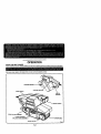
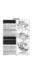
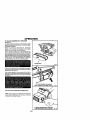
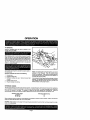
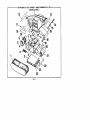
OWNER'S
MANUAL
MODEL NO.
315.117120
CAUTION:
Read Rules for
Safe Operation
and All Instructions Carefully
CRAI:TSMAK
3 Inch
Belt Sander
Double Insulated
Warranty
Introduction
Operation
Maintenance
®
Repair Parts
Designed exclusively for an_pl<t e_L _
SEARS, ROEBUCK AND CO., Hoffman Esfate_,]L
612547-768
11-C0
6_9
FULL ONE YEAR WARRANTY ON CRAFTSMAN
BELT SANDER
Ifthis Craftsman Belt Sander fails to_gr
ive complete sattsfaction within one_yl
ear from the date of purchase, RETURN
IT TO THE NEAREST SEARS STORE IN THE UNITED STATES, and _ears will repair it, free of charge.
Ifthis Craftsman Belt Sander is used for commercial or rental purposes, this warranty applies for only 90 days from
the date of purchase.
This warranty gives you specific legal rights, and you may also have other rights which vary from state to state.
Sears, Roebuck and Co., DEPT. 817 WA, Hoffman Estates, IL 60179
INTRODUCTION
DOUBLE INSULATION is a concept in safety, in electric
power tools, which eliminates the need for the usual three
wire grounded power cord and grounded supply system.
Wherever there is electric current in the tool there are two
complete sets of insulation to protect the user. All expOSed
metal parts are isolated from iotemal metal motor components with protecting insulation.
IMPORTANT - Servicing of a tool with double insulation
requires extreme care and knowledge of the system and
should be performed only by a qualified service technician,
For service we suggest you return the tool to your nearest
Sears Store for repair. Always use original factory replacement parts when servicing.
GENERAL
Your Craftsman Belt Bender is suitable for coarse, medium and fine sanding of wood, metals, plastics and other materials. It
is ideal when used for smoothing rough boards, chamfering, rounding edges and many other general Sanding applications.
it is also an excellent tool for removing paint, varnishes, and stains, its balanced design makes it easy to use.
RULES FOR SAFE OPERATION
READ ALL INSTRUCTIONS
1.
2.
3,
4.
5.
6.
KNOW
manual
tations
related
GUARD
YOUR POWER TOOL - Read owner's
carefully. Learn its applications and limias well as the specific potential hazards
to this tool.
AGAINST
ELECTRICAL
SHOCK BY
PREVENTING
BODY
CONTACT
WITH
GROUNDED
SURFACES.
For example: Pipes,
radiators, ranges, refrigerator enclosures.
KEEP GUARDS IN PLACE and in working order.
KEEP WORK AREA CLEAN. Cluttered areas
and benches invite accidents.
AVOID DANGEROUS
ENVIRONMENT,
Don't
use power tool in damp or wet locations or expose to rain. Keep work area well lit.
KEEP CHILDREN
AND VISITORS
AWAY. All
visitors should wear safety glasses and be kept a
safe distance from work area. DO not let visitors
contact tool or extension cord.
7. STORE
IDLE
TOOLS.
When
not in use tools
should be stored in a dry, high or focked-up
- out of the reach of children.
place
8.
DON'T FORCE TOOL. It will do the job better
and safer at the rate for which it was designed.
9. USE RIGHT TOOL. Don't force small tool or at-
tachment to do the job of a heavy duty tool. Don't
use tool for purpose not intended - for example Don't use a circular saw for cutting tree limbs or
logs.
10. WEAR PROPER APPAREL.
No loose clothing
or jewelry to get caught in moving parts. Rubber
gloves and non-skid footwear are recommended
when working outdoors, Also, wear protective hair
covering to contain long hair and keep it from
being drawn into air vents.
Page 2
RULES FOR SAFE OPERATION (Continued)
11. ALWAYS
12,
13.
14,
15.
16,
WEAR
SAFETY
GLASSES.
Everyday
eyeglasses have only impact-resistant lenses;
they are NOT safety glasses.
PROTECT YOUR LUNGS. Wear a face or dust
mask if operation is dusty,
PROTECT YOUR HEARING. Wear hearing protection during extended periods of operation.
DON'T ABUSE CORD. Never carry tool by cord
or yank it to disconnect from receptacle. Keep
cord from heat, oil and sharp edges.
SECURE WORK, Use clamps or a vise to hold
work, Both hands are needed to operate the tool.
DON'T OVERREACH,
Keep proper footing and
balance at all times. DO not use on a ladder or
unstable support.
17. MAINTAIN
TOOLS
WITH CARE. Keep tools
sharp at all times, and clean for best and safest
performance.
Follow instructions
for lubricating
and changing accessories.
18. DISCONNECT
TOOLS. When not in use, before
servicing, or when changing sanding belts, attachments,
blades, bits, cutters, etc., all tools
should be disconnected
from power supply.
19. REMOVE ADJUSTING
KEYS AND WRENCHES.
Form habit of checking to see that keys and
adjusting wrenches are removed from tool before
turning it on,
20. AVOID ACCIDENTAL
STARTING,
Don't carry
rlugged-in
tools with finger on switch, Be sure
switch is off when plugging in,
21, MAKE SURE YOUR EXTENSION
CORD IS IN
GOOD CONDITION.
When using an extension
cord, be sure to use one heavy enough to carry
the current your product will draw, An undersized
cord will cause a drop in line voltage resulting in
loss of power and overheating, A wire gage size
(A,W.G,) of at least 16 is recommended for an
extension cord to0 feet or less in length. A cord
exceeding 100 feet is not recommended,
if in
doubt, use the next heavier gage. The smaller the
gage number, the heavier the cord,
22, OUTDOOR
USE EXTENSION
CORDS. When
toot is used outdoors, use only extension cords
suitable for use outdoors. Outdoor approved cords
are marked with the suffix W-A, for example SJTW*A or SJOW-A.
23. NEVER USE THIS OR ANY POWER SANDER
FOR WET SANDING,
Failure to comply can result in electrical shock causing serious injury or
worse,
24. KEEP HANDS AWAY FROM SANDING AREA.
25. NEVER USE IN AN EXPLOSIVE ATMOSPHERE.
26.
INSPECT
27.
damaged, have repaired at your nearest Sears
Repair Center, Stay constantly aware of cord
location.
INSPECT EXTENSION CORDS PERIODICALLY
TOOL CORDS
PERIODICALLY
aed if
and replace if damaged.
KEEP HANDLES
DRY, CLEAN, AND FREE
FROM OIL AND GREASE. Always use a clean
ctoth when cleaning. Never use brake fluids, gasoline, petroleum-based products or any strong solvents to clean your tool,
29. STAY ALERT. Watch what you are doing and
use common sense. Do not operate tool when
you are tired. Do not rush.
30, CHECK DAMAGED
PARTS. Before further use
of the tool, a guard or other part that is damaged
should be carefully checked to determine that it
wnl operate properly and perform its intended
function. Check for alignment of moving parts,
binding of moving parts, breakage of parts, mounting, and any other conditions that may affect its
operation. A guard or other part that is damaged
should be properly repaired or replaced by an
authorized service center unless indicated elsewhere in this instruction manual,
31, DO NOT USE TOOL IF SWITCH DOES NOT
TURN IT ON AND OFF, Have defective switches
28,
replaced by an authorized service center.
Inspect for and remove all nails from lumber before sanding.
33. DRUGS, ALCOHOL, MEDICATION.
Do not operate tool while under the influence of drugs,
alcohol, or any medication.
34, DO NOT USE THIS SANDER FOR OVERHEAD
SANDING. Overhead sanding coold result in dropping sander or loss of control, These situations
could result in an accident resulting in possible
serious injuPJ.
35. WHEN SERVICING
USE ONLY IDENTICAL
CRAFTSMAN
REPLACEMENT
PARTS.
36, POLARIZED PLUGS. To reduce the risk of electric shock, this tool has a polarized plug (one
blade is wider than the other). This plug will fit in a
polarized outlet only one way. If the plug does not
fit fully in the outlet, reverse the plug. If it still does
not fit, contact a qualified electrician to install the
proper outlet. Do not change the plug in any way.
37. SAVE THESE INSTRUCTIONS.
Refer to them
32,
Normal sparking of the motor could ignite fumes.
Page 3
frequently and use to instruct others who may
use this tool. tf you loan someone this tool. loan
them these instructions also.
OPERATION
KNOW
YOUR
BELT
SANDER
Before attempting to use your sander, familiarize yourself with all operating features and safety requirements. See Figure I.
Make sure power supply is 120 volts, 60 I_t, AC only (nOrmal household current).
TRACKING SCREW--_
"LOCK'ON" BuI"rON
REAR HANDLE
SWITCH
TRIGGER
HANDLE
DRIVE ROLLER ASSEMBLY
PLATEN ASSEMBLY
(INCLUDES YOKE ASSEMBLY)
*SANDING BELT
FRONT PULU =
Page
Fig. I
4
OPERATION
SWITCH
The switch of your sander is equipped with a "lock-on"
feature which is convenient when sanding for extended
periods of time. To lock-on, simply depress the switch
trigger, push in the lock button located on the side of the
handle, then while holding the lock button pushed in, release
the switch tdgger. See Figure 2.
To release the lock, depress the tdgger and release it.
BE SURE TOOL IS NOT IN THE "LOOK-OR" POSITION
BEFORE CONNECTING TO POWER SUPPLY SOURCE.
DO Nor LOCK THE SWITCH TRIGGER ON JOBS WHERE
YOUR SANDER MAY NEED TO BE STOPPED SUDDENLY.
PREPARING
Fig. 2
FOR OPERATION
Forease of operationyour sander has a fronthandic and a rear
handle. These handles allow two-hand operation which aid in
maiofainicgcontrol,keepingsanding area level withworkpiece,
and keepinghands clear of sanding pelt. When operating your
sanderalways holdthe fronthandle with your left hand and the
rear handle with your right hand as shown in Figure 3.
CORRECT
Fig. 3
Always operate your sander as shown in Figure 3.
Selecting the correct size gdt and type sanding belt is an
extremely important step in achieving a high quality sanded
finish. Standard 3 in. x 21 in. sanding pelts made of aluminum
oxide, silicon carbide, and other synthetic abrasives are best
for power sanding. Natural abrasives, suchas flintand garnet
are too soft for economical use in power sanding.
In general, coarse gdt sanding halts will remove the most
matedal and finer grit sanding belts will produce the best
finish in all sanding operations. The condition of the surface
to be sanded will determine which gritwill do the job. If the
surface is rough, start with a coarse grit and sand until the
surface is uniform. Medium gdt may then be used to remove
scratches left by the coarser grit and finer gtit used for
finishing of the surface. Always continue sanding with each
grit until sudace is uniform.
Page 5
KEEP HANDS AND FINGERS
AWAY FROM THESE AREAS AT ALL TIMES
Fig. 4
OPERATION
INSTALLING/REMOVING
1.
SANDING BELT
UNPLUG YOUR SANDER.
Tension must be released on the front pulley in order to
install and remove sanding belt. To release tension on the
front pulley, you must depress the front pulley untilthe notch
in the platen assembly wilt fit the slot, then rotate the notch
onto the slot. See Figure 5.
To release
2.
tension
on front
pulley:
NOTCH
Place the front pulley ofyour sander against the corner
of a workbench as shown in figure 6. NOTE: The left
side of your sander should be positioned as shown so
that the motor housing will not come in contact with
workbench when front puitey is compressed.
3.
Hold your sander firmly with both hands and push the
frent pulley against the comer ofworkbench as shown in
figure 6.
4.
Once the front pulley has been compressed enough to
allowtbe notch in the platen assernbly tofitthe sloton the
platen assembly, rotate your sander in the direction of
the arrows shown in figure 6.
5.
When propedy compressed, tbe front pulley wilt rernain
in a retracted position as shown in figure 7. This allows
new sanding belt to be instaited, and frees old sanding
ban so it can be removed.
To install
6.
sanding
FRONT
SLOT
PULLEY
TO RELEASETENSION: COMPRESS FRONT PULLEY
AND ROTATE NOTCH iNTO SLOT
Fig. 5
/ \
belt:
Install new sanding belt making sure arrow inside of belt
is pointing in the direction of sander rotation. Sander
rotation is clockwise when looking into open side of
sander. See Figure 8.
NOTE: The arrow inside sanding belt indicates the bait's
direction of rotation, while the direction of rotation of the
drive roller indicates the sanders direction of rotation.
Fig. 6
Sanding belts installed backwards can
create a hazardous condition.
7.
Roughly align sanding belt to its correct position, then
apply tension to front pulley. When correctly adjusted,
the outer edge of the sanding belt will be even with the
outer edge of the platen assembly.
8.
Apply tension to ftont pulley by pressing or tapping itwith
e blockof wood in the direction of the anew as shown in
Figure9. The pulley willsnap beck into operatingposition,
FRONT
PULLEY
IN RETRACTED
SHOWN
PosnloN
Fig. 7
Page 6
OPERATION
TO ADJUST
SANDING
BELT
TRACKING
See Figure 10.
TO adjust sanding belt tracking, connect sander to power
supply. Hold sander as shown in figure 1O. pultswitchtdgger
and release immediately.
NOTE: This position is for adjustments only. Sanding belt
should not be in contact with workpiece or any foreign
objects when making belt tracking adjustments,
Observe tracking of sanding belt, If the sanding belt rur_s
inward,slOWlyturnthe trackingscrew clockwise. Itthe sanding
belt runsoutward, slowly turnthe tracking screw counterclockwise,This should be done untilyouare sure belt willnot runoff
sander, or come in contact withintemal pads, After inslallinga
new sanding belt, it may become necessary to change the
adjustmentseveral times untilthe belt becomes pUable.
SANDING BELT
Fig. 8
When you are sure the beltwill not rubagainst internal pads,
start your sander and fine adjust the tracking screw untilthe
belt stabilizes. See Figure 10.
When correctly adjusted, the outer edge of the bch will be
even with the outer edge of the platen assembly. Belt lifewill
be greatly increased ifa few seconds are spent adjustingthe
belt tracking,
TO PLACE TENSION ON SANDING
BELT, PRESS OR TAP FRONT PULLEY
Fig. 9
TO ADJUST SANDING BELT TRACKING:
TURN TRACKING SCREW AS SHOWN
Fig. 10
REPLACE TORN SANDING BELTS IMMEDIATELY.
NOTE: The front pulley of your sander was not designed for
contour sanding. Sanding on the front pulley could cause
irregularity in sanding belt tracking.
Page 7
OPERATION
TO OPERATE
Clamp or otherwise secure the work to prevent it from
moving under your sander.
Before placing sander on work surface, squeeze the switch
trigger and let the motor reach its maximum speed, then
lower your sander to the work surface with a slight forward
motion,Using the rear handle to control your sander and the
front handle only to guide it, move itslowly over the work. See
Figure 1I, Allowing your sander to remain in one place will
result in an uneven surface,
Your sander was designed to provide the proper weight on
the sanding belt.
Excessive pressure will result in the following:
sander from workpiece.
1. Uneven work.
2.
3.
4.
Clogged sanding belts.
Premature sanding belt wear.
increase.
Possible motor burnout.
5.
Irregular sanding belt tracking.
EXTENSION
NOTE: If the sanding bed moves while sanding, you may be
applying too much pressure.
When this occurs remove
If belt tracking
sanding belt will return to its normal
the drive miter and front pulley.
Removal rate will not
is properly
and correct
Use a coarser belt when heavy sanding
is desired,
adjusted,
position on
not heavy
pressure. The importance
of this cannot be over-emphasized. Weight has been built into the tool to give the most
efficient
pressure
at the proper
location.
CORDS
The use of any extension cord willcause some loss of power. TO keep the loss to a minimumand to prevent tool overheating,
use an extension cord that is heavy enough to car_ the current the tool willdraw. The smaller the gauge number of the wire,
the greater the capacity of the cable. For example, 16 gauge wire has more capacity than 18 gauge w=re+ Follow the
recommended cord sizes on the chart provided to determine the minimum wire size required in an extension cord,
Extension Cord Length
25-50 Feet
50-100 Feet
Wire Gauge Size (A.W.G.)
16
14
When working with your tool outdoors, use an extension cord suitable for outdoor use and so marked, Outdoor use extension
cords are marked with the letters "WA" on the cord's jacket.
CAUTION: Keep extension cords away from the Sanding area and position the cord so that it willnot get c_ught on lumber.
tools, etc., dudog sanding.
Page 8
MAINTENANCE
GENERAL
Only the parts shown on parts list. page 11. are intended to
be repaired or replaced by the customer. AH other paris
represent an important part of the double insulation system
and should be serviced only by a qualified Sears service
technician.
Avoid using solvents when cleaning plastk_parts. Never let
liquids get instdethis tool.Alse, never immerse any pad ofthis
tool into a liquid. Most plastics are susceptible to various
types of commemial solvents and may be damaged by their
use. Use clean cloths to remove dirt, carbon dust, etc.
When electrictools are used on fiberglass boats, sportscars,
wallboard, spackling compounds, or plaster, it has been
foundthat they are subject to accelerated wear and possible
premature failure, as the fiberglas_ chips and gpadings are
highly abrasive to bearings, brushes, commutator, etc.
Consequently itis not recommended that this tool be used for
extendedworkon anyfiberglassmatedal, wstlpoard,spacklidg
compounds, or plaster. Dudng any use on these materials, it
is extremely impOdantthat the tool is cleaned frequently by
b_owingwith an air jet.
LUBRICATION
All of the bearings in this tool are lubricated with a sufficient amount of high grade lubricant for the life of the unit under normal
operating conditions. Therefore, no fudher lubrication is required,
ELECTRICAL
CONNECTION
This tool has a precision built electric motor, g should be connected to a power supply that Is 120 volts, 60 HZ, AC only
(normal household current). Do not operate this tost on direct current (DC). A voltage drop of more than 10 percent will
cause a loss of power and overheating. If your tool does not operate when plugged into an outlet, double-check the power
supply.
_
can result in severe eye damage. Before beginning power tool operation, always wear safety /
goggles or safety glasses with side shields and a full face shield when needed. We /
The °pemti°n °f any sander can resun In f°mign °bJects being thr°wn iat° y°ur eyes' which 1
:.;:.;::eyog,.sas
ora,a.da,.
.at g
, .e...J
P_e9
CRAFTSMAN
3 IN. BELT SANDER -- MODEL NUMBER 315.117120
SEE NOTE"A" PAGE 11
12
13
24
2O
4
21
1
\
22
25
Page10
CRAFTSMAN
3 IN. BELT SANDER -- MODEL NUMBER 315.117120
I
The model number will be found on a plate attached to the motor housing. Always mention the model number in all corrM,=_pondence
regarding your
CRAFTSMAN SANDER or when ordedng repair parts.
J
SEE BACK
PAGE
FOR PARTS
ORDERING
INSTRUCTIONS
PARTS LIST
Key
Part
No,
Number
Description
Quart.
Key
No.
Part
Number
968732-001
Deemriptlen
Quart.
Banding Belt (3 In. x 21 In.) ........................... 1
14
2
998380-o01
Wear Plate .....................................................
1
15
971822-001
Spring .............................................................
1
3
971425001
Platen Assembly (Includes Key NO. 4) .......... 1
16
706239-313
Washer ...........................................................
1
4
968730-CO1
Spdog .............................................................
1
17
607406-001
5
617966-031
• Screw (#8-10 x 3/4 In. Pan Rd.) .................... 3
18
624276-001
6
968703-007
* Screw (#8-32 x 1/2 in. Pan Hal.) .................... 1
19
968733-001
7
931055-813
Washer ...........................................................
1
20
622167-012
Retaining Ring ...............................................
8
607406-007
Hex Nut (#3/16-18 Left Hand Threads) ......... 1
21
998373002
Idler Roller w/Bearings ................................... 1
1
***
• Tracking Screw (#5/16-18 x 2 In.) .................. 1
• Hex Nut (#3/16-18)
°*STD541231 ................. 1
Washer ...........................................................
1
• Screw (#1/4-14 x 1/2 In. T.F. Rat Hd,) ........... 1
1
9
968716-(X)2
Roller w/Cover (Includes Key No. 24) ............ 1
22
999954-002
10
971156-001
Logo Plate ......................................................
t
23
968703-003
11
971152-001
Logo Plate ......................................................
1
24
968726-001
Roller Cover ...................................................
1
12
971132-001
Label ..............................................................
1
25
998378-001
BacPJngPad ...................................................
1
13
968725-001
Data Plate ......................................................
1
612547-768
Owner's Manual
Idler Roller Shaft ............................................
1
• Screw (#8-32 x 1/4 In. Pan Hal,T F.) ............. 2
NOTE: "A "- The usembly shown represents an important part of the Double Ins ulsted System. To avoid the passib_lily of alteration or damage
to the system, service should be parformed by your nearest Sears Repair Center. Contact your nearest Sears Retail Store,
***
Standard Hardware Its_n -- May Be Purchased Locally
Available From Div. 98 -- Source 980.00
Sanding Belts in assorted grits for both sanding wood and metal may be obtained from your nearest Sears Retail Store.
J
Page 11
For repair of major brand appliances in your own home...
no matter who made it, no matter who sold it!
1-800-4-MY-HOME
s" Anytime, day or night
(1-800-466-4663)
www,sears.com
To bring in products such as vacuums, lawn equipment and electronics
for repair, call for the location of your nearest Sears Parts & Repair Center.
1-800-488-1222
A.ytime,
dayoroight
www.sears.com
For the replacement parts, accessories and owner's manuals
that you need to do-it-yourself, call Sears PartsDIrectSUT
1-800-366-PART
(1-800-366-7278)
6_.m.- 11p.m.CST,
To purchase or inquire about a Sears Service Agreement:
1-800-827-6655
7 a.m. - 5 p.m. CST, Mon.-
Para pedirserviciode reparacibna domicilio,
y para ordenar piezas conentrega a domicilio:
1-886-SU-HOGAR s.
(1-888-784-6427)
© Soo,_, Roebu(_ ar_ Co
_
7 daysa week
Sat.
Au Canada pour see/iceen fran;ais:
1-877-LE-FOYER
_
(1-877-533-6937)
® Re_slered Tre,demark / _M Tradornl_k of S_ars, Roebuck attd CO.
® Meuca ReOlsVe,da I _N Ma,ca de F_LmCS de Sears, Roobuck Kd CO
.....