1
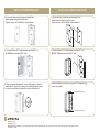
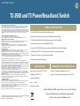
QUICK START GUIDE
T2-2500 and T3 PowerBroadband Switch
Radio Frequency Interference Requirements- FCC
Note: This equipment has been tested and found to comply with the limits for a Class A digital
device, pursuant to Part 15 of the FCC rules. These limits are designed to provide reasonable
protection against harmful interference when the equipment is operated in commercial
environment. This equipment generates, uses, and can radiate radio frequency energy and, if not
installed and used in accordance with the instruction manual, may cause harmful interference to
radio communications. Operation of this equipment in a residential area is likely to cause harmful
interference in which case the user will be required to correct the interference at his own
expense.
SUMMARY OF INSTALLATION STEPS
1. Install the Switch in the central telephone room
Radio Frequency Interference Requirements- Canada
This Class A digital apparatus complies with Canadian ICES-003.
Cet appareil numérique de la classe A est conforme à la norme NMB-003 du Canada.
2. Install cross-connect wires with the existing premises wiring
Marking and European Economic Area (EEA)
WARNING: This is a Class A product. In a domestic environment this product may cause radio
interference in which case the user may be required to take adequate measures.
3. Configure the Switch following the configuration shown below
Statement of Compliance
Motorola/Symbol hereby declares that this device is in compliance with all the applicable
Directives, 2004/108/EC and 2006/95/EC. A Declaration of Conformity may be obtained from
http://www2.symbol.com/doc/.
4. Install the in-room filters and WallPlate CPEs
T2-2500 and T3 Switch
CAUTION: For installation only in a Restricted Access Location by trained service personnel.
CAUTION: Equipment must be connected to an earthed mains socket-outlet.
CAUTION: To reduce the risk of fire, use only No. 26 AWG or larger telecommunication line cord.
CAUTION: The power supply cord plug serves as the main disconnect for the product. The socketoutlet shall be installed near the product and be readily accessible.
CAUTION: Voltages present which are above TNV-3 (POTS) limits. A cover must be installed over
the punch down blocks with a HV (High Voltage) warning label (supplied).
The maximum operating ambient temperature is 50 degrees Celcius.
When installing the Switch in an equipment rack, consider the following potential hazards:
Elevated Operating Ambient Temperature - If installed in a closed or multi-unit rack assembly, the
operating ambient temperature of the rack environment may be greater than the room ambient.
Therefore, consideration should be given to installing the equipment in an environment compatible
with the manufacturer's maximum rated ambient temperature (Tmra).
Reduced Air Flow - Installation of the equipment in a rack should be such that the amount of air
flow required for safe operation of the equipment is not compromised.
Mechanical Loading - Mounting of the equipment in the rack should be such that a hazardous
condition is not achieved due to uneven mechanical loading.
Circuit Overloading - Consideration should be given to the connection of the equipment to the
supply circuit and the effect that overloading of circuits might have on overcurrent protection and
supply wiring. Appropriate consideration of equipment nameplate ratings should be used when
addressing this concern.
Reliable Earthing - Reliable earthing of rack-mounted equipment should be maintained.
Particular attention should be given to supply connections other than direct connections to the
branch circuit (e.g., use of power strips).
m2 and MC-802 WallPlate
CAUTION: Use only power supplies listed in the user manual
When using your telephone equipment, basic safety precautions should always be followed to
reduce the risk of fire, electric shock and injury to persons, including the following:
1. Do not use this product near water, for example, near a bath tub, wash bowl, kitchen sink or
laundry tub, in a wet basement or near a swimming pool.
2. Avoid using a telephone (other than a cordless type) during an electrical storm. There may be a
remote risk of electric shock from lightning.
3. Do not use the telephone to report a gas leak in the vicinity of the leak.
For EU Customers: All products at the end of their life must be returned to Motorola for
recycling. For information on how to return product, please go to:
www.motorola.com/recycling/weee.
5. Connect a 12VDC wall power supply to the WallPlate, link with the Switch
6. When the link LED is solid, test the connection for speed and quality
7. Enable Line Power for the line being installed
8. Remove the wall power supply
ACCESS METHODS
MINIMUM REQUIRED CONFIGURATION
login using console, HTTP, Telnet
system> interface dsl enable port(1-25)
IP address: 192.168.1.3
system> interface remote enable port(1-25)-(1-2)
Console: 9600-8-N-1
User:
admin
Password: <blank>
Contact Motorola PBN support for access to User Guides,
Command References and detailed usage guides
email: [email protected]
INSTALL M2 ETHERNET WALLPLATE
INSTALL MC-802 WIRELESS WALLPLATE
1. Loosen existing screws by approximately 6mm
Attach bracket using the keyhole slots
Tighten screws until the brack is firnly attached
1. Loosen existing screws by approximately 6mm
Attach bracket using the keyhole slots
Tighten screws until the brack is firnly attached
2. Connect 150mm RJ11 cable between vertical RJ11 on
m2 WallPlate and existing RJ11 jack
2. Connect 50mm RJ11 cable between vertical RJ11 on
MC-802 WallPlate and existing RJ11 jack
3. Align cover with the bracket, using a slight angle to start the
bottom hook. Apply firm pressure to snap the cover into place.
4. Install two set screws (supplied) in the pre-drilled holes
3. Attach WallPlate to bracket using two 6/32 thread-forming
screws (supplied)
6/32 thread forming screws
6/32 thread forming screws
www.motorola.com
570343-001-00 rev A
MOTOROLA and the stylized M Logo are registered in the U.S. Patent and Trademark Office. All other product or service names are the property of their registered owners.
© Motorola, Inc, 2009