1
SEA/RS
OWNERS
MANUAL
MODEL NO.
315.115041
CAUTION:
Read Rules for
Safe Operation
and Instructions
Carefully
CRRFTSMRN"
7 INCH ELECTRIC
SANDER
DOUBLE INSULATED
Warranty
SAVE THIS
MANUAL
FOR
FUTURE REFERENCE
Introduction
Operation
Maintenance
Repair Parts
612547-627
10-00
Dee1 ned excluslvel for and sold only b
SEARS, ROEBUCK AND C_.., Hoffman Estates, _L 60179
@
Pdnted In U.S.A.
FULL ONl_ YEAR WARRANTY ON CRAFTSMAN SANDER
If this Craftsman Sander fails to ;ale comnptette
satisfaction within one year from the date of purchase, RETURN IT
TO THE NEAREST SEARS STORE iN THE UNITED STATES, and Sears wiil repair it, free of charge.
If this Craftsman Sander is used for commercial or rental purposes, this warranty applies for only 90 days from the
date of purchase,
This warranty gives you specific tegal dghts, and you may also have other dghts which val_ from state to state.
Sears, Roebuck snd Co,, DEPT. 817 WA, Hoffman Estates, IL 60179
INTRODUCTION
DOUBLE _$ULATION
is a concept in safety, in electric
power tools, whk_,heliminates the need for the usual three
wire grounded power cord and grounded supply system.
Wherever there is aiect rlc current in the tool there are two
complete sets of insulatton to protect the user. All exposed
metal parts ere isolated from internal metal motor components _i_ protecting inlu_Oon,
IMPORTANT - Servicing of a tool with double aisulatk_
requires extreme care and knowledge of the system and
should be performed only by a qualified service technician,
For service we suggest you return the too_to your nearest
Sears Store for repair. Always use original factory replacement parts when servicing,
RULES FOR SAFE OPERATION
READ ALL INSTRUCTIONS
1. KNOW YOUR POWER TOOL - Reed owner's
manual carefully. Learn its applications and
limitations as well as the specific potential
hazards related to this tool.
2. GUARD AGAINST ELECTRICAL SHOCK
BY PREVENTING BODY CONTACT WITH
GROUNDED
SURFACES.
For example:
Pipes, radiators, ranges, refrigerator enclosures.
3. KEEP GUARDS IN pLACE end in working
order.
4. KEEP WORK AREA CLEAN, Cluttersd aroas
and benches invite accidents.
5, AVOID DANGEROUS ENVIRONMENT. Don't
use power tool in damp or wet locations or
expose to rain. Keep work area well lit.
6. KEEP CHILDREN AND VISITORS AWAY.
8. DON'T FORCE TOOL. It will do the job better
and safer at the rate for which it was designed.
USE RIGHT TOOL. Don't force small tool or
attachment to do the job of a heavy duty tool.
Don't use tool for purpose not intended - for
example - Don't use a circular saw for cutting
tree limbs or logs.
10. WEAR PROPER APPAREL. No loose cloth9.
ing or jewelry to get caught in moving parts.
Rubber gloves and non-skid footwear are recommended when working outdoors. Also,
wear protective hair covering to contain long
hair and keep it from being drawn into air
vents.
11. ALWAYS WEAR SAFETY GLASSES. Ev-
All visitors should wear safety glasses and be
12.
kept a safe distance from work area. Do not
let visitors Contact tool or extension cord.
7. STORE IDLE TOOLS. When not in use tools
13.
should be stored in a dry, high or lacked-up
place - out of the reach of children.
Page2
eryday eyeglasses have only impact-resistant lenses; they are NOT safety glasses.
PROTECT YOUR LUNGS. Wear a face or
dust mask if cutting operation is dusty.
PROTECT YOUR HEARING. Wear hearing
protection during extended periods of operation.
RULES FOR SAFE OPERATION (Continued)
14. DON'T ABUSE CORD. Never can_ tool by
cord or yank it to disconnect from receptacle.
Keep cord from heat, oil and sharp edges.
15. SECURE WORK. Use clamps or a vise to
hold work. Both hands are needed to operate
the tool.
16. DON'T OVERREACH. Keep proper footing
and balance at all times. Do not use on a
ladder or unstable support.
17. MAINTAIN TOOLS WITH CARE. Keep tools
sharp at all times, and clean for best and
safest performance. Follow instructions for
lubricating and changing accessories.
18. DISCONNECT TOOLS. When not in use, before servicing, or when changing attachments,
blades, bits, cutters, sandpaper, etc., all tools
should be disconnected from power supply.
19, REMOVE
ADJUSTING
KEYS
AND
26. INSPECT TOOL
approved cords are marked with the suffix WA, for example - SJTW-A or SJOW-A.
23, NEVER
USE THIS OR ANY POWER
SANDER FOR WET SANDING. Failure to
comply can result in electrical shook causing
sedous injury or worse.
24. KEEP HANDS AWAY FROM SANDING
AREA.
25, NEVER USE IN AN EXPLOSIVE ATMOSPHERE. Normal sparking of the motor could
ignite fumes.
PERIODICALLY
CALLY and replace if damaged.
28. KEEP HANDLES DRY, CLEAN, AND FREE
FROM OIL AND GREASE. Always use a
clean cloth when cleaning. Never use brake
fluids, gasoline, petroleum-based products or
any strong solvents to clean your tool.
29. STAY ALERT. Watch what you are doing
and use common sense. Do not operate toct
when you are tired. Do not rush.
30. CHECK DAMAGED PAWrS. Before further
WRENCHES. Form habit of checking to see
that keys and adjusting wrenches are removed
from tool before turning it on.
20. AVOID ACCIDENTAL
STARTING.
Don't
camj plugged-in tools with finger on switch.
Be sure switch is off when plugging in.
21. MAKE SURE YOUR EXTENSION CORD IS IN
GOOD CONDmON. When using an extension
cord, be sum to use one heavy enough to carry
the oJrrentyour productwill draw. An undersized
cord will cause a drop in line voltage resulting In
loss of power and overheating.A wire gage size
(A.W.G.) of at Isest 12 is recommendedfor an
extensioncord 100 feet or less in length. A cord
exceeding 100 feet is not recommended. If in
doubt,use the next heaviergege, The smallerthe
gage number,the heavierthe cord,
22. OUTDOOR
USE EXTENSION
CORDS.
When tool is used outdoors, use only extension cords suitable for use outdoors. Outdoor
CORDS
and if damaged, have repaired at your nearest Sears Repair Center. Stay constantly
aware of cord location.
27. INSPECT EXTENSION CORDS PERIODI-
31.
32.
33.
34.
35.
36.
Page3
use of the tool. a guard or other part that is
damaged should be carefully checked to dstermlne that it will operate propedy and perform its Intandsd function. Check for alignment of moving parts, binding of moving pads,
breakage of pads, mounting, and any other
conditions that may affect its operation. A
guard or other part that is damaged should be
propady repaired or replaced by an authorized service center unless indicated else.
where in this instruction manual.
DO NOT USE TOOL IF SWITCH DOES NOT
TURN IT ON AND OFF. Have defective
switches replaced by an authorized service
center.
Inspect for and remove all nails from lumber
before sanding.
DRUGS, ALCOHOL, MEDICATION. Do not
operate too_while under the influenceof drags,
alcohol, or any medication.
WHEN SERVICING USE ONLY IDENTICAL
CRAFTSMAN REPLACEMENT PARTS.
POLARIZED PLUGS. To reducothe dskofsiectdc
shOck,this tool has a polarizedplug{one blade is
widerthantheother).Thisplugwillfitin a belarized
outletonly one way. If the plugdoes notfit fvilyin
the outlet, reverse the plug. If it sti, does not fit,
contacta qualitiedekyJtrisianto installthe proper
oudet. Do notchange the plugin any way.
SAV_ THESE INSTRUCTIONS, Review them
frequently and use them to instruct others
who may use this toot. If you loan someone
this tool, loan them these instructions also.
l_e
opemUon
of any sander
can muir
In foreign
objects
being thrown
Into your eye_, which
can rlmult In leverl
eye danlage.
Before beginning
I_WM to_ _ra_n,
always wmlr sahib/
g_lglel
or safety
glmme_
with IIIde shields
and • full f_o
shield
when needed.
We
reconlmend
Wide Vision Safety Mask for use over eyeglasses
or standard
_ety
glasses
with
side
shields,
Ilvllllable
at ,Sears Retail
Pa_e 4
Storlm.
OPERATION
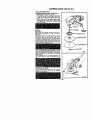
SWITCHACTUATOR
(OLAC_
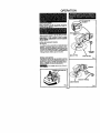
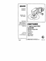
KNOW YOUR SANDER
Before attempting to use your sander, familiarize
yourself wffh aft ooerating features and safety requirements. See Figure 1.
Make sum power supply is 120 volts, 60 Hz, AC only.
SWITCH TRIGGER
(RED}
DISCONNECT
YOUR SANDER
FROM POWER
SUPPLY WHILE ASSEMBLING PARTS OR MAKING
ADJUSTMENTS.
INSTALLING
AUXILIARY HANDLE
See Figure 2.
An auxiliary handle is packed with your 8antler for ease of
operation. The auxiliary handle can be installed on either
sJdeot tha unlt and must always be used to prevent loss
of control and possible serious injurJ. To Instat1.position
washer into place and start threads into the threaded hole
in the gear housing. Tlghten cap screw securely.
AUXILIARY
HANDLE
BACK-UP PAD
SPINDLE LOCK BuTroN
A spindis lock button has been provided for locking
the spindle of your tool In a stationary position. It is
located on the side of the gear houefeg as shown in
flgt;re 3. Depress and hold the lock button while _nstal,ng, changing, or removing accessories.
_Do
not engage spendfe Jock whJle spin.
SPfNDLE,
Fig. 3
Page 5
BACK-UP
DISC
Fig, 1
OPERATION
SWITCH
An important new feature of your sander is the
sw_tch desigrn. It has multi-finger control for use
when operating at different angles or sandJng positions and to help reduce fatigue.
tt also has a lock-on feature in the switch for added
utility and convenience
on extended work re*
ulrement$.
_refully
read and understand the following instructions for correct operation of the switch before connecting your sander to power supply.
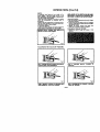
TO ACTIVATE SWITCH
To start your sander, depress the switch trigger and
switch actuator at the same fime_ See Figure 4.
DEPRESS SWITCH TRIGGER AND
UATOR TO START YOUR SANDER
SWITCH
AC.
(Cont'd)
NOTE: PARTS OF THE SWITCH CAN BE EASILy
IDENTIFIED BY THEIR COLOR. THE SWITCH TRIGGER IS RED. THE 8WrTCH ACTUATOR IS BLACK.
"LOCK-ON"
SWITCH
1. Start your sander by depressing the switch tdgger
and switch a(;tuator.
2. Continue to hold your sander _nthe "on" position
with your fingertips and release the switch trigger.
See Figures 5 and 6,
3. Release the switch actumtor and grasp your
sander by the handle as shown in figure 7.
TO RELEASE '%OCK-ON" FEATURE
1. Depress the switch trigger and release it. See
Figure a.
Fig. 4
TO ACTIVATE
THE "LOCK-ON"
FEATURE:
Fig.
Fig. 5
STEP
2.
"LOCK-ON"
STEP 1. DEPRESS SWITCH TRIGGER AND SWITCH
ACTUATOR WITH YOUR FINGERTIPS
TEP 3. GRASP BY HANDLE FOR SANDING
YOUR SANDER IN "LOCK-ON"
POSITION
RELEASE
SWITCH
TRIGGER
TO
Fig. 7
Fig. 8
WITH
STEP 4. DEPRESS SWITCH TRIGGER TO RELEASE
"LOCK-ON" FEATURE
Page 6
OPERATION
INSTALLING
SANDING
(Cont'd.)
DISC
DISCONNECT SANDER FROM POWER SUPPLY.
1. Assemble pans as shown in Figure g.
2. Place washer on spindle, then thread rubber backup pad onto spindle. Lock spindle by depressing
spindle lock button and hand tighten back-up pad.
3. Position back-up disc and sanding disc in place
and thread flange nut onto spindle. Tighten flange
nut securely
by turning the sanding disc
clockwise by hand.
SANDING
See Figure 10
The material being sanded should be held firmly.
Secure small workpleces in a vise or clamp to
workbench.
Hold your sander in front and away from you with
beth hands. With the sanding disc clear of the
workpiece, start your sander and let the motor reach
its maximum speed, then lower to the work surface
at a slight 5 to 8 degree angle. See Fig. 10. Do not
allow the tool to remain in one place, Th_s will cause
uneven sanding or gouging of the work. Keep your
sander slowly moving over the work.
AUXILIARY
HANDLE
PAD
_FLANGE
This tool was designed so that the weight of the tool
alone will provide adequate weight on the sanding
disc. Extra pressure will only result in uneven work,
slower sanding from slower speed, and possible
motor bum-out.
Upon completion of work, or a sanding operation, lift
your sander away from work surface before turning
off,
NUT
Fig. 9
To remove paint, varnish, or rust, sand with an
openkote type s_ndlng disc.
Another method of removing paint or rust is by wire
brushing. The wire cup brush may be threaded
directly onto the spindle.
Fig. 10
P_e7
OPERATION
For ease of operation and maintainin
proper control, hold your Sander ON LY by the handles provided.
Also. as mentioned previously, hold it firmly with
both hands at all times. NEVER grasp the front or
sides of the tool body; or by any other means during
use,
the power co_, cord plug, extension cord and extension cord plugs. They could get caught in the
rotating spindle, wrap around it, and cause possible
serious thju W.
EXTENSION
DO NOT ATTEMPT TO USE AS A BENCH TOOL
Fig. 11
CORDS
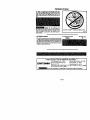
The use _ any ex_ns_n co_ will cause some lossof power.
To keep _e k_ss_ a minimum ar_ to preve_ to_ ove_eat_g, follow the recommended cord sizes on the chad at the
dght. When t0ol is used outdoors, use only extension com_
suitable for outdoor use and so marked. Extensioncords are
available at Seam Retail S_ms.
Extension Cord Length
2_50 Ft.
50-100 Ft.
Wire Size A.W.G.
16
14
THE FOLLOWING RECOMMENDED ACCESSORIES ARE CURRENT AND
WERE AVAILABLE AT THE TIME THIS MANUAL WAS PRINTEO.
7-Inch Sanding Kit ( 9
11157)
Wire Cup Brush Wheel ( 9
64106)
Cl AFTSM RN®.,u,.,nu._
O*,de
Sand,rig
C,.os Ca.,_thg
_.se
(__t_._c)
Guard ( 9 1711)
Grinding Wheel ( g 64101)
(Available through Catalog Sales Only) 100' 14 A.W.G. Ex_Cord
50' 14 A.W.G. Ext, Cord ( 9 5821)
_I_
The use of attachments
(9
or accessories not listed above might be hazardous.
Page 8
83508)
MAINTENANCE
GENERAL
O_y the parts shown on parts list, page 11, are intended to
be repaired or replaced by the customer. NI other pads
represent an important pad of the double insulation system
snd should he sew]ced only by a quatlrLedSears service
technician.
Avoid using solvanto when cleaning plastic pads. Most
plastics are susceptible to various types of commercial
solvents and may be damaged by their use, Use clean
aloths to remove dirt, carbon dust, atc.
When electric tools are used on fiberglass boats, sports
cars, wallboard, spackling compounds, or plaster, it has
been found that they are su_ent to accelerated wear and
possible premature failure, as the fibergl_)ss chips and
grindlngs are highly abrasive to bearings, brushes,
commutator, etc. Co(lsequently, it is not recommended that
thistoal be used for extended work on any fiberglassmaterial,
wallboard, spackling compounds, or plaster. During any
use on fiberglass it is extremely important that the tool is
cleaned frequently by blowing with an air jet
LUBRICATION
AHof the beadngs in this tool are lubricatedwith a sufficient
amount of high grade lubricant for the life of the unit under
normal operating conditions. Therefore, no further lubriCation is required.
Page 9
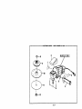
CRAFTSMAN
SANDER
-- MODEL NUMBER
2
315.115041
SEE NOTE "A"
PAGE 11
5
I
P_elO
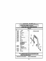
CRAFTSMAN
SANDER
-- MODEL
NUMBER
315.115041
in_ m
commgondance
regarding
yourS4_IOERor
whenordedag
repairpelts.
i "nle
odel
numbe_
will
befound
on
aplale
altachedtothemotor
hour.
Alwaysmentionthemodalnumber
SEE
BACK
PAGE
FOR
PARTS
ORDERING
PARTS
Key
No.
Part No,
1
g68172.001
Description
Data Rate ...............................
2
gG4BIT4.O01
Gear Housing Cover ......................
I
3
gIM182*001
Logo Plate ..............................
1
Auxiliary
1
S
Handle .........................
e
(121721-0_Z
7
M_2.004
8
e22141-8"13
Washer .................................
1
9
81/2S1-001
Back-Up Pad .............................
1
m
Back-Up Disc ............................
1
7 Inch Sar_Ing Discs 'hN17/8 IrL hole
(Item No. _
FkaeGr_
9-25291 Idledkml Gdt, and
9-25292 Coarse Grit) .......................
1
12 817224-00t
Flange Nut ..............................
1
13 967862.000
Bail Handle Assembly
(Includes Key HOS. 14 and 15)............
1
"Cap Screw (#3J8-24 x 1 In. Soc. Hd.) ..........
2
10
11
"°*
Washer .................................
Otmn.
1
• Screw (#8-10 x 2 In. Fd. Hd.) ................
14
S676rdS.0_2
15
703776-03$
Washer .................................
812547.62?
Owner's Manual
LIST
OPTIONAL
BAIL HANDLE
1
2
2
NOTE: "A". 111easmim_ altown mpclmm_ an Important pert of the Double Immbde¢l Sytitem. TO m_)l¢l the
gosalMIty of ammnlen or dsmego to the Syst*m, ram,k=* should be godormed by your rmmzst _m
Ragelr C*mtmr. Cold,act your nNrRt Seers Retag _l_re.
• Standard Hmrdwlre Barn - May Ba Purchmmd Locally
_* Avalllble
Page 11
I
INSTRUCTIONS
At Your Ne_zmt S4mrl RMall Store
For repairof majorbrand appliancesIn your own home...
no matterwho made it, no matterwho soldit!
1-800-4-MY-HOME
s" Anytime,day or night
(1400-469-4663)
www.sears.com
To bringin productssuchas vacuums,lawn equipment and electronics
for repair,call for the locationof your nearest Sears Parts & Repair Center.
1-800-488-1222
Anytime,day or night
www.sears.com
For the replacementparts,accessoriesand owner'smanuals
thatyou need to do-it-yourself,call Sears PartsDIrects_!
1-800-366-PART
sa.m.-11p.m.CST,
(1-800-366-7278)
7 days 8 week
www.sears.com/partsdlrect
To purchaseor inquireabouta Sears ServiceAgreement:
1-800-827-6655
7 a.m. - 5 p.m,CST. Mon.- Sat.
Pare pedir serviciode reparack_na domicilio,
y pare ordenar piezascon entrega a domicilio:
1-888-SU-HOGAR =
Au Caqada pourservice en frangais:
1-877-LE-FOYER
s.
(t -877-533-69_)
(1-888-784-6427)
D I:N_e0
O _llirl.
_
lirid r*_
Tradem'ark / _ Trl_
O M4UO_Regilttad_ / 'u M_
de Fibdr*l
of S_llrl. FI_
IJI Sears, I=1_
end CO
ll_d CO.