1
GDAŃSK
integra_u_en 08/10
Firmware version 1.08
Alarm Control Panel
USER
MANUAL
WARNING
In order to avoid any operational problems with the control panel, it is recommended that you
become familiar with this manual before you start using the equipment.
Making any construction changes or unauthorized repairs is prohibited. This applies, in
particular, to modification of assemblies and components. Maintenance and/or repair
operations should be performed by authorized personnel (i.e. the installer or factory service).
The INTEGRA 24, INTEGRA 32, INTEGRA 64 and INTEGRA 128 control panel should be
connected to analog lines only. Connecting its telephone circuit to a digital network (e.g.
ISDN) may cause damage to the equipment. In case of changing the analog line to the digital
one, it is necessary to contact the alarm system installer.
Pay special attention if the telephone line used by the control panel is frequently busy and/or
failures are reported concerning the line and/or monitoring. Report such situations to the
alarm system installer immediately.
CAUTION!
The alarm system is fitted with a battery. After expiry of its lifetime, the battery must not be
thrown away, but disposed of as required by the existing regulations (European Directives
91/157/EEC and 93/86/EEC).
The latest EC declaration of conformity and product approval certificates
are available for downloading on website www.satel.pl
The INTEGRA alarm control panels INTEGRA 24, INTEGRA 32, INTEGRA 64 and
INTEGRA 128 meet requirements as per CLC/TS 50131-3, Grade 3, and have been certified
by Det Norske Veritas Certification AS, Norway.
Environmental class of the INTEGRA series control panels: II.
INTEGRA
SATEL
1
New features in firmware versions 1.07 and 1.08
System operation
The new INT-CR proximity card arm/disarm device enables arming /
disarming and alarm clearing in many partitions by means of proximity
cards, keyfobs and other passive transponders.
Users
The installer can define a minimum length of codes used in the
system.
New right: ZONE ISOLATION.
Data entering
A new, more intuitive way of entering hexadecimal values and names.
Arming /
disarming with 2
codes
The installer can configure the system so that the validity period of the
first code in the partition is always 60 seconds (in such a case, the
user does not program any validity period for the first code).
Zone bypasses
The zones can be permanently bypassed (isolated) i.e. they will not be
unbypassed on disarming the partition they belong to.
User functions
The ZONE BYPASSES function has taken on the role of submenu
offering the following functions:
– INHIBIT
– ISOLATE
The PERMANENT DLOADX ACCESS option has been added to the
CHANGE OPTIONS submenu.
2
User Manual
INTEGRA
CONTENTS
1.
2.
3.
4.
5.
GENERAL ............................................................................................................................4
ABOUT THIS MANUAL ............................................................................................................4
TECHNICAL RELIABILITY OF THE ALARM SYSTEM......................................................................4
ALARM SYSTEM OPERATING COSTS .......................................................................................5
INTEGRA CONTROL PANEL .................................................................................................5
5.1 BASIC FUNCTIONS OF THE CONTROL PANEL....................................................................................5
5.2 CONTROL PANEL PERFORMANCE ...................................................................................................6
6.
OPERATION OF INTEGRA CONTROL PANEL ..........................................................................6
6.1 LCD KEYPADS ..............................................................................................................................8
6.1.1
Keypads with mechanical keys.........................................................................................................8
Display................................................................................................................................................. 10
Keys..................................................................................................................................................... 10
LED indicators ..................................................................................................................................... 10
6.1.2
Audible signals in keypads .............................................................................................................11
6.1.3
Using LCD keypad..........................................................................................................................12
6.1.4
Entering data by means of the LCD keypad...................................................................................13
Selection from the single-choice list .................................................................................................... 14
Selection from the multiple-choice list in the text mode ...................................................................... 14
Selection from the multiple-choice list in the graphic mode ................................................................ 14
Entering decimal values ...................................................................................................................... 14
Entering names ................................................................................................................................... 14
6.1.5
Reading alarm source name ..........................................................................................................15
6.1.6
Proximity card reader (INT-KLCDR-GR/INT-KLCDR-BL only).......................................................15
6.2 PARTITION KEYPADS ...................................................................................................................16
6.3 MULTIFUNCTIONAL KEYPAD WITH PROXIMITY CARD READER..........................................................20
6.3.1
6.3.2
6.3.3
6.4
6.5
6.6
6.7
6.8
Operation in partition keypad mode (INT-S/SK) .............................................................................20
Operation in partition keypad mode with proximity card reader (INT-SCR) ...................................21
Operation in entry keypad mode (INT-ENT)...................................................................................23
CODE LOCKS ..............................................................................................................................24
PROXIMITY CARD AND DALLAS CHIP READER ..............................................................................26
CODES AND USERS .....................................................................................................................26
PREFIXES ...................................................................................................................................27
PROXIMITY CARDS/DALLAS CHIPS ..............................................................................................28
6.8.1
6.8.2
6.8.3
6.8.4
6.8.5
6.8.6
Adding proximity card / DALLAS chip by means of LCD keypad ...................................................28
Adding proximity card / DALLAS chip by means of DLOADX program ...........................................28
Adding proximity card / DALLAS chip by means of GUARDX program ...........................................28
Deleting cards/DALLAS chips by means of LCD keypad...............................................................29
Deleting proximity card / DALLAS chip by means of DLOADX program .........................................29
Deleting proximity card / DALLAS chip by means of GUARDX program .........................................29
6.9 APT-100 KEYFOBS .....................................................................................................................29
6.9.1
Adding keyfob by means of LCD keypad .......................................................................................30
Entering the serial number manually................................................................................................... 30
Reading the serial number during transmission.................................................................................. 31
6.9.2
Adding keyfob by means of DLOADX program................................................................................31
Entering the serial number manually................................................................................................... 31
Reading serial number during transmission........................................................................................ 31
6.9.3
Removing keyfob by means of LCD keypad ..................................................................................32
6.9.4
Removing keyfob by means of DLOADX program...........................................................................32
6.9.5
Assigning zones to buttons by means of LCD keypad ...................................................................32
6.9.6
Assigning zones to buttons by means of DLOADX program............................................................32
6.9.7
Assigning the outputs to the LEDs by means of LCD keypad........................................................33
6.9.8
Assigning the outputs to the LEDs by means of DLOADX program ................................................33
6.9.9
Configuring event generation rules by means of LCD keypad .......................................................33
6.9.10 Configuring event generation rules by means of DLOADX program ................................................34
INTEGRA
SATEL
3
6.10 SYSTEM ARMED MODE ................................................................................................................ 34
6.11 ALARMS ..................................................................................................................................... 37
6.12 ALARM MESSAGING BY TELEPHONE ............................................................................................. 37
6.13 ANSWERING PHONE CALLS ......................................................................................................... 38
6.14 OTHER FUNCTIONS USING TELEPHONE LINE................................................................................. 39
6.15 SMS CONTROL ONLY INTEGRA 128-WRL................................................................................. 40
7.
USER FUNCTIONS ............................................................................................................. 40
7.1 MAIN MENU ................................................................................................................................ 40
7.1.1
User function menu ........................................................................................................................40
7.2 DESCRIPTION OF USER FUNCTIONS ............................................................................................. 43
View cleared alarms .................................................................................................................................44
System reset.............................................................................................................................................44
Disarm ......................................................................................................................................................44
Clear alarm ...............................................................................................................................................44
Clear other alarms ....................................................................................................................................44
Abort voice messaging .............................................................................................................................44
Arm ...........................................................................................................................................................44
Arm (2 codes) ...........................................................................................................................................44
Disarm (2codes) .......................................................................................................................................45
Defer auto-arming.....................................................................................................................................45
Set auto-arming delay ..............................................................................................................................45
Arming mode ............................................................................................................................................46
Cancel 1st code ........................................................................................................................................46
Change own code.....................................................................................................................................46
Change prefix ...........................................................................................................................................47
Masters .....................................................................................................................................................47
Users ........................................................................................................................................................47
Zone bypasses .........................................................................................................................................50
Inhibit ....................................................................................................................................................50
Isolate ...................................................................................................................................................51
Set time.....................................................................................................................................................51
Troubles....................................................................................................................................................51
Events.......................................................................................................................................................52
Reset zones..............................................................................................................................................53
Clear latched outputs................................................................................................................................53
Fire door opening finished ........................................................................................................................53
Change options.........................................................................................................................................53
Tests .........................................................................................................................................................55
Service access..........................................................................................................................................57
Open door.................................................................................................................................................57
Outputs control .........................................................................................................................................57
Controlling the MONO SWITCH type of output.......................................................................................58
Controlling the BI SWITCH type of output...............................................................................................58
Controlling the REMOTE SWITCH type of outputs ....................................................................................58
Controlling the SHUTTER UP and SHUTTER DOWN type of outputs..........................................................58
Service mode............................................................................................................................................59
Take SM over ...........................................................................................................................................59
Downloading .............................................................................................................................................59
8.
9.
10.
11.
12.
13.
CONFORMANCE TO CLC/TS 50131-3 REQUIREMENTS ......................................................... 60
APPENDIX A...................................................................................................................... 61
APPENDIX B...................................................................................................................... 63
APPENDIX C ..................................................................................................................... 64
BRIEF DESCRIPTION OF OPERATING THE SYSTEM FROM KEYPAD ............................................ 69
HISTORY OF THE MANUAL UPDATES..................................................................................... 70
4
User Manual
INTEGRA
1. GENERAL
Thank you for choosing the product offered by the SATEL Company. High quality, large
number of functions and simple operation are the main advantages of our alarm control
panel. Wishing you full satisfaction with the choice you made, we are always ready to provide
you with professional assistance and information on our products. Please note that, besides
the control panels, SATEL manufactures many other components of alarm systems. Detailed
information on our full offer can be found nationwide at retail dealers offering our products, on
website www.satel.eu.
2. ABOUT THIS MANUAL
This Manual allows you to familiarize yourself with the basic operation of modules designed
to control the operation of alarm systems based on the INTEGRA control panels and with the
functions performed by these panels. The INTEGRA includes alarm control panels:
INTEGRA 24, INTEGRA 32, INTEGRA 64 and INTEGRA 128 and INTEGRA 128-WRL.
The part OPERATION OF INTEGRA CONTROL PANEL of this Manual describes the modules that
control operation of the control panel and how they should be used. It also presents some
functions related to the alarm system operation, and includes some basic information on
functioning of the system and use of the telephone line by the control panel.
The part USER FUNCTIONS of this Manual contains full specification of functions accessible
from the alphanumeric LCD keypad.
The text in this Manual contains some technical terms: for explanation please refer to
APPENDIX B at the end of this Manual.
Please read carefully the entire manual since familiarity with the control panel functions will
allow you to take full advantage of the equipment possibilities. The control panel can perform
functions that are nor related directly to monitoring. The use of all control panel functions and
the operational efficiency of the entire system depend to a large extent on its installation
method and its programming by the installer. The control panel may perform its functions in
many ways, which are defined when installing and programming the system. Therefore, you
should obtain from the installer more detailed information on how the alarm system operates
and how it should be used.
All situations in which the way of the control panel operation depends on previous installer
decisions (made at the time of programming) are additionally marked by inserting the PROG
symbol (after description of the situation).
The term "service", as used in this manual, refers to the user who takes care of the alarm
system and is authorized to use the service code. He can be installer, maintenance
technician, security guard employed for protection of the facility, etc.
3. TECHNICAL RELIABILITY OF THE ALARM SYSTEM
The alarm system is composed of technical devices whose reliability is vital for the
effectiveness of the facility protection. The elements of the alarm system are exposed to the
impact of various outside factors, including weather conditions (outside sirens), atmospheric
discharges (overhead telephone lines, power lines, outside sirens), mechanical damage
(keypads, detectors, etc.). Only routine inspection of the alarm system operation will make it
possible to keep a high level of burglary and fire protection.
The control panel is provided with a number of safeguards and auto-diagnostic functions for
[TROUBLE] LED is lit, it indicates that the
testing the system reliability. If the keypad
control panel has detected a fault. You should immediately respond to such a signal,
and, if necessary, consult the installer.
INTEGRA
SATEL
5
It is necessary to periodically carry out a functional test of the alarm system. Check that the
control panel responds to violation of individual detectors, that their fields of view are not
masked, that there is a reaction to opening protected windows, and that sirens and telephone
messaging work normally.
Detailed instructions on the system testing should be provided by the installer. It is
recommended that the installer carry out periodic maintenance of the alarm system, when
ordered by the user.
It is in the user's best interest to anticipate and plan beforehand appropriate procedures in
case the control panel signals an alarm condition. It is important that he should be able to
verify the alarm, determine its source on the basis of keypad information, and take
appropriate measures, e.g., to organize evacuation.
4. ALARM SYSTEM OPERATING COSTS
The main task of the control panel is signaling and efficient reporting of alarm situations and,
in the case of the monitoring function, providing the monitoring station with real-time
information about the protected facility status. Realization of these functions, based on the
use of telephone line, entails financial costs. Generally, the level of costs incurred by the
alarm system owner depends on the amount of information the control panel has to transfer
to the monitoring station. A failure of the telephone links, as well as incorrect programming of
the control panel, may to a large degree increase these costs. Such a situation is usually
related to an excessive number of connections made.
The installer can adjust functioning of the alarm system to the specific conditions and kind of
the protected site, however it is the user who should decide if his or her priority is transferring
information at any price, or, if some technical problems occur, the control panel is allowed to
skip some events, the reception of which has not been confirmed by the monitoring station.
5. INTEGRA CONTROL PANEL
The INTEGRA alarm control panel is designed for the security supervision in small, mediumsize and large facilities. The supervision is not limited to protection against burglary, but it
may also include monitoring of the facility for correct functioning for 24 hours a day.
The status of the alarm system is monitored on a continuous basis. Violation of any alarm
system component triggers the so-called tamper alarm. The control panel responds to signals
from individual detectors and decides whether to signal the alarm or not. Since various
detectors may be connected to the control panel, the type and way of alarming depends on
the way of control panel programming (the control panel may respond in one way to a signal
from fire detector and in another way to a signal from a water level detector).
The control panel makes it possible to group zones and detectors connected to them into socalled partitions, and to freely determine which partition is to be supervised (armed).
Activation of any detector from such a group (hereinafter called “zone violation") may trigger
an alarm. A great advantage of the control panel is its high flexibility in determination which
partitions may be armed at the moment.
5.1 BASIC FUNCTIONS OF THE CONTROL PANEL
• signaling burglary, attack, fire, technical and auxiliary alarms,
• monitoring – communication with the monitoring stations (real time sending detailed
information on selected events in the protected facility),
• telephone messaging on alarms – either with the use of a voice message or to a pager,
6
User Manual
INTEGRA
• answering phone calls (this function is protected with a separate code) which allow to:
− inform the user on the system status,
− control via telephone some of the control panel functions, which were programmed by
the service,
• real-time printout of information regarding all or selected events that have occurred in the
alarm system with the use of an external printer,
• control of access to the facilities through doors provided with electromagnetic locks,
• monitoring individual alarm system components (e.g. power supplies, batteries, wiring) for
correct operation.
5.2 CONTROL PANEL PERFORMANCE
• various means of operating and controlling the security system:
– LCD keypad,
– partition keypad,
– proximity card reader,
– 433 MHz keyfob (optionally, with INT-RX module installed),
– 868 MHz keyfob (INTEGRA 128-WRL control panel and, optionally, the other control
panels, if ACU-100 controller with firmware version 2.0 or later is connected),
– computer with DLOADX or GUARDX program installed,
– SMS message (INTEGRA 128-WRL control panel and, optionally, the other control
panels, if GSM-4S module is connected),
– Internet browser (optionally, with ETHM-1 module connected),
– cellular phone with MobileKPD application installed (optionally, with ETHM-1 module
connected),
– palmtop (PDA or MDA) with suitable application installed (optionally, with ETHM-1
module connected).
• installer defined descriptions of zones and partitions for easy identification of the alarm
source,
• visible system date and time to better check the real-time dependent functions for correct
operation,
• optional display of the status of partitions (up to 16 selected or all),
• available viewing of the alarm/trouble log (or detailed memory of all events) with textual
description of event, name of zone, module, partition or the user who operates the system,
together with accurate time of the event occurrence,
• monitoring, depending on the mainboard, of up to 8 independent alarm systems and up to
32 armed independently partitions,
• individual control of the output types of MONO SWITCH, BI SWITCH, REMOTE SWITCH,
SHUTTER UP and SHUTTER DOWN,
• dynamically changeable menu (dependent on authority level) to provide access to
a number of user functions, the selection made by accepting the suitable function from the
list shown on the LCD keypad screen,
• key shortcuts to facilitate calling frequently used functions,
• service note shown on LCD display.
6. OPERATION OF INTEGRA CONTROL PANEL
The SATEL company offers a number of devices that enable operating the INTEGRA control
panel, including, first and foremost, the LCD keypads, but also keyfob transmitters, proximity
INTEGRA
SATEL
7
card arm/disarm devices, partition keypads, code locks, as well as proximity card / DALLAS
chip readers.
The LCD keypads and proximity card arm/disarm devices INT-CR may be used to control
many partitions in various objects. The partition keypads control just one partition. Individual
control devices are assigned by the installer to specified partitions. The users may operate
the control panel only if they have access to partitions operated by particular keypads. This
means that the partitions assigned to the user at the stage of creating/editing a new user (see
DESCRIPTION OF USER FUNCTIONS ÆUSERS) must correspond to those operated by the
keypad. The list of partitions operated by LCD keypad or proximity card arm/disarm device
INT-CR is defined by the installer.
Example: LCD keypad controls partitions 1,2,3,4,5 and 6. The user has access to partitions
5,6,7 and 8. Hence, using this LCD keypad he can control partitions 5 and 6.
A similar principle applies to partition keypads, code locks, proximity card readers and
DALLAS chip readers. With keypads, the user can control the partitions he has access to,
and he may open the doors with code locks and proximity card/DALLAS chip readers, to
opening of which he has been authorized. The installer defines the list of users of individual
partition keypads, code locks and readers (separately for each module).
The access to the control panel control functions and the vital information on the system
status are protected with a CODE (the code is a combination of 4 to 8 digits). In systems
which require enhanced protection, it is possible to extend the code by a prefix (1 to 8 digits),
periodically changed by the object master user code.
The installer can allow some functions to be run in the keypad without entering the code
PROG. Press and hold down the keys below for 3 seconds to:
[1]
– view zones status,
[4]
– view partitions status,
[5]
– view alarms log,
[6]
– view troubles memory,
[7]
– view current troubles,
[8]
– switch on/off chime signal in LCD keypad,
[9]
– toggle the display between standby mode and partitions state presentation mode,
X or W – view messages about partition alarms (use the same keys to scroll through the
list of messages),
S or T – view messages about zone alarms (use the same keys to scroll through the list of
messages),
– trigger the auxiliary alarm (for example, calling for medical aid),,
– trigger the fire alarm,
– trigger the panic alarm. The installer can determine whether the triggered panic
alarm will be an audible one (initiating the alarm signaling), or a silent one (with
no signaling).
It is recommended that the above way of calling functions be only available in
LCD keypads which are not accessible to unauthorized personnel.
If the installer has allowed for the quick arming option, the armed mode can be enabled
without entering any code, by pressing in turn the following keys:
− [0] and [#] – fully armed;
− [1] and [#] – fully armed plus zone bypasses with BYPASSED IF NO EXIT option enabled;
− [2] and [#] – armed without interior;
− [3] and [#] – armed without interior and without entry delay.
8
User Manual
INTEGRA
In case of the LCD keypad, the partitions indicated by the installer will be armed. In case of
the partition keypad, the partition to which the keypad is assigned will be armed. The types of
armed mode are described in section SYSTEM ARMED MODE.
Press and hold down simultaneously the S and T keys for approx. 40 seconds to restart the
keypad and display the information about keypad and control panel firmware version.
6.1 LCD KEYPADS
SATEL offers a wide range of keypads which enable operating the INTEGRA alarm control
panels. The INT-KSG keypad with touch keys is described in a separate manual.
6.1.1 Keypads with mechanical keys
SATEL's portfolio includes the following mechanical keypads:
− INT-KLCD-GR/INT-KLCD-BL
− INT-KLCDR-GR / INT-KLCDR-BL
− INT-KLCDK-GR
− INT-KLCDL-GR / INT-KLCDL-BL
− INT-KLCDS-GR / INT-KLCDS-BL
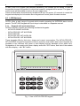
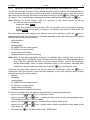
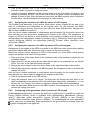
These keypads differ by their size, shape and current consumption. The INT-KLCDR-GR /
INT-KLCDR-BL keypad incorporates a built-in proximity card reader. Most of the keypads are
available in two versions: with green or blue display and key backlight of the same color.
Designation of the models with green display ends with "GR" letters, and that of the models
with blue display – with "BL" letters.
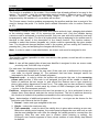
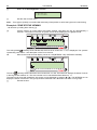
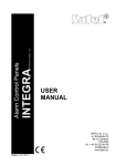
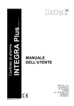
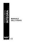
Fig. 1. View of INT-KLCDR-GR keypad.
INTEGRA
SATEL
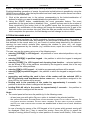
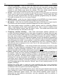
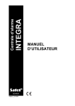
Fig. 2. View of INT-KLCDS-GR keypad.
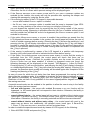
Fig. 3. View of INT-KLCDK-GR keypad.
9
10
User Manual
INTEGRA
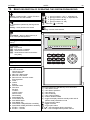
Display
The keypads are provided with a 2x16 character display with backlighting. The backlighting
mode is determined by the installer. In the standby mode, the display shows the current date
and time, it can also permanently show the keypad name. The format of displayed
information is defined by the installer. The lower display line can be used to show the current
status of selected partitions (up to 16), the displayed symbols being as described in the
TESTS function. The first character in the lower line (from left) shows the status of the lowest
number partition, as selected by the installer. The following numbers show information on the
partitions in the ascending order.
The LCD display can also show important information transmitted by the service using the
so-called SERVICE MESSAGE. The displayed text can contain up to 29 characters and can be
displayed either permanently, or for a specified period of time. It can be visible either to all
users, or only to some of them after entering the access code.
Keys
Situated under the display are keys, which can be backlit (the backlighting mode being
determined by the installer), and which are used for:
• entering codes,
• moving through menu and selecting appropriate functions from the list,
• entering data for called functions.
The [#] and [ok] keys are electrically connected to each other and may be used
interchangeably. Therefore, if using the [#] key is mentioned elsewhere in the following part
of this manual, it should be understood that the [ok] key may also be used instead.
LED indicators
6 LEDs present information on the system state.
-
(red) – permanent lighting of the LED indicates alarm. After expiry of the alarm
time, the blinking LED means alarm memory. The LED is going off after deletion of
alarm (see: ALARMS).
ALARM
Note: The LED may not signal alarms in the armed mode if the installer has enabled the
option DO NOT SHOW ALARM IF ARMED, as required by the CLC/TS 50131-3 standard.
-
(yellow) – blinking light indicates that a technical trouble has occurred in the
system. Emergency situations causing this LED to light up are described further in this
Manual (see DESCRIPTION OF USER FUNCTIONS ÆTROUBLES). The LED goes
temporarily off when the LCD keypad is in partially armed mode (at least one partition
accessible to the given LCD keypad is armed) or in fully armed mode (all partitions
accessible to the LCD keypad are armed) PROG. The LED is blinking until the
troubles are viewed and the trouble memory is reset (the option TROUBLE MEMORY
UNTIL REVIEW enabled) or until the trouble cause stops (the option TROUBLE MEMORY
UNTIL REVIEW disabled) PROG.
- ARMED (green) – the LED is blinking when some partitions are armed and lights
steadily when all partitions operated by the keypad are armed.
- SERVICE (green) – the LED is blinking when the control panel is in the service mode
(function only available to the user having a service code).
TROUBLE
Note: The service mode limits normal operation of the control panel. Alarms from most
zones (except for the following types: PANIC, 24H CASH MACHINE, and 24H VIBRATION)
as well as tamper alarms are not signaled. To restore normal operation of the control
panel, you should exit the service mode, because the control panel will not
automatically return to its normal operating mode.
INTEGRA
-
SATEL
11
GROUP (two
green LEDs) – used in graphic mode functions to indicate which data set is
currently displayed. The LEDs can show the number of zones or outputs, or indicate
the corresponding expander bus. (See: section SELECTION FROM THE MULTIPLE-CHOICE
LIST IN THE GRAPHIC MODE).
LED
INDICATION
DESCRIPTION
left side/upper
right side/lower
OFF
OFF group 1; numbers
1–32
(n)
OFF
ON group 2; numbers
33–64 (32+n)
ZONES/
OUTPUTS
ON
OFF group 3; numbers
65–96 (64+n)
ON
ON group 4; numbers
97–128 (96+n)
first expander bus
OFF
OFF bus 1 numbers (addresses) 0-31 (DEC)
system addresses 00–1F (HEX)
EXPANDER
BUSES
second expander bus
OFF
ON bus 2 numbers (addresses 0-31 (DEC)
system addresses 20–3F (HEX)
n – number of LCD keypad field
6.1.2 Audible signals in keypads
When using the keypad the following signals, characteristic of some situations, can be heard
PROG.
• One long beep – refusal of arming - the zone, which shouldn't be violated at the time of
arming, is violated (PRIORITY option), there was a trouble with the battery, expander, or
keypad. The refusal includes all zones selected for arming. Also, warning of the system
failure - prior to arming.
• Two long beeps – unknown code/card, exit function/menu, or unavailable function.
• Three long beeps – the code is recognized, but the function called is not accessible
(for example, temporary partition blocking is activated or the user has no access to
partitions operated from the keypad).
• Two short beeps – selection accepted – entering more detailed menu level.
• Three short beeps – acknowledgement of arming or disarming.
• Four short and one long beeps – acceptance of execution of the selected function.
• Three pairs of short beeps – it is necessary to change the code (for example, another
user, when changing his code, indicated the combination of digits identical with that in the
given user code; the code validity is expiring).
Additionally, the following situations may be signaled:
• Alarm in partition – continuous beep.
• Fire alarm – long beep every second.
• Countdown of entry delay – 2 short beeps every second.
Note: The signaling of entry delay countdown by 2 short beeps refers to the LCD keypads
type INT-KLCD-GR/BL and INT-KLCDR-GR/BL with firmware in version 1.05, and to
the keypads type INT-KLCDL-GR/BL, INT-KLCDS-GR/BL and INT-KLCDK-GR with
firmware in version 6.05. In keypads with earlier firmware versions, the entry delay
countdown is signaled by short beeps every 3 seconds.
• Countdown of exit delay – long beeps every 3 seconds, completed with a series of
short beeps (for 10 seconds) and a single long beep. The way of “exit delay" signaling
informs that the countdown is ending prior to arming.
12
User Manual
INTEGRA
• Auto arming delay countdown (timer-controlled partitions) – a series of 7 sounds
(of diminishing length).
• Chime in LCD keypad – five short beeps – this is a response to activation of some
detectors when the zone is disarmed.
6.1.3 Using LCD keypad
Operation of the system from LCD keypad starts with entering the user CODE and pressing
the key marked [#], [ok] or [*]. The control panel response (accessible functions) after
pressing the [#] or [ok] key is different than that after pressing [*].
[CODE][#] or [CODE][ok] you get access to functions of arming/disarming type,
[CODE][*]
you get access to all functions in the user menu to which the user
is authorized.
Example: When you enter your code and press [#], the control panel will make available the
functions of partition arming (provided that no partition, operated from the LCD keypad, is
already armed) or disarming (if any of partitions is armed). In the event of alarm occurrence
in the system, the control panel may cancel this alarm and provide access to the function of
partition disarming (if the user is authorized to do that). When the function of telephone
messaging is activated – the CLEAR VOICE MESSAGING function may appear in menu. When
the user has access to a single partition only, entering the code and pressing [#] results in
immediate arming or disarming (if the partition is armed).
Entering the code and pressing [*] displays the list of functions accessible from the USER
MENU. The USER MENU provides also access to the following functions: ARMING and
DISARMING (if some partitions are armed). When all partitions are armed, the function ARMING
will not be accessible.
Note: Entering a wrong code (not recognized by the panel) three times may:
− trigger an alarm PROG,
− block a keypad for 90 sec. After this time each next wrong code entering will block
the keypad PROG.
The specific feature of the control panel is the dynamic changing of the accessible menu,
dependant on the system programmed parameters, as well as on the authorization level of
the user who entered the code. The user get access only to those function in the user menu
to which he is authorized.
In order to call some functions more quickly, the user can use some SHORTCUT KEYS.
Having called the menu ([CODE][*]), type in the suitable digit or combination of digits – the
control panel will enter directly the called function.
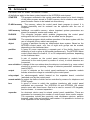
The following user functions are assigned to the digits / combinations of digits:
1 Change own code
2 Users/Masters
21 New user / New master
22 Edit user / Edit master
23 Remove user / Remove master
Note: The shortcuts to the MASTERS submenu and functions available therein are only active
when the service is not authorized to edit users.
3 none
4 Zone bypasses
41 Inhibit
42 Isolate
5 Events
INTEGRA
6
7
8
9
0
SATEL
13
51 Selected events
52 All events
Set time
Troubles
Outputs control
Service mode
Downloading
01 Start DWNL-RS
02 Finish DWNL-RS
03 Start DWNL-MOD.
04 Start DWNL-TEL
05 Start DWNL-CSD [only INTEGRA 128-WRL]
06 Start DWNL-GPRS [only INTEGRA 128-WRL]
07 ETHM-1 – DloadX
08 ETHM-1 – GuardX
Note: The shortcuts in the DOWNLOADING menu are available when the control panel
configuration and settings make it possible to use the selected function.
The installer can assign functions to the arrow keys to facilitate the everyday operation of
the system. These functions are called in the following way:
[CODE] S
[CODE] W
[CODE] X
[CODE] T
One of the following functions can be assigned to each arrow:
− Arming (full)
− Arming (without interior zones)
− Arming (without interior zones, without entry delay)
− Disarming
− Alarm clearing
− Zones bypassing (inhibit)
− Bypass clearing
− Output MONO ON
− Output BI switch state
− Output BI ON
− Output BI OFF
− Arming (full+bypasses)
For each of the functions the installer determines the number of partition, zone or output it
refers to. The user, who wants to perform the given function must have an appropriate
authority level and access to the selected partitions.
All user functions, which are accessible from LCD keypad, are described in section
DESCRIPTION OF USER FUNCTIONS.
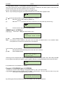
6.1.4 Entering data by means of the LCD keypad
The ways of data entering can differ, depending on the function and the type of data. In most
cases, the data are saved on pressing the [#] or [ok] key. Some functions require acceptance
of the entered data by pressing an additional key (the control panel can be configured by the
14
User Manual
INTEGRA
installer so that pressing the key [1] will be required). The [*] key enables exiting the function
without saving the changes (which can result in quitting the user menu).
Selection from the single-choice list
Shown in the upper line of display is description of the function, and in the lower one – the
currently selected item. You can scroll through the list of items, using the direction keys: T
(down) and S (up). The X and W keys are not used.
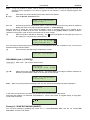
Selection from the multiple-choice list in the text mode
Shown in the upper line of display is description of the function, and in the lower one - an
item which can be selected. You can scroll through the list of items, using the direction keys:
T (down) and S (up). An additional symbol is displayed in the upper right corner:
– item not selected (e.g. partition, zone, output, etc.);
– item selected (e.g. partition, zone, output, etc.).
Press any numeric key to change the currently displayed symbol to another one.
Selection from the multiple-choice list in the graphic mode
The graphic mode is available in some functions which enable multiple selection (e.g.
selection of the partitions which are to be armed; selection of the zones which are to be
bypassed, etc.). The keypad will enter the graphic mode on pressing the X or W key. The
and symbols are used to present on the display the status of items available within the
function – these can be e.g. partitions, zones, outputs, etc. ( – item not selected; – item
selected). The numbers around the display are used for numbering the items. The X key will
move the cursor to the right, and the W key – to the left . Pressing any numeric key will
change the currently displayed symbol to another one. The blank spaces (where no symbol is
displayed) are the unavailable items (e.g. partitions which cannot be armed or disarmed;
zones which cannot be bypassed, etc.) over which you cannot hover the cursor.
The display makes it possible to simultaneously present up to 32 items in the graphic mode,
while the number of items in some functions can be higher (e.g. there are 128 zones in the
system). If this is the case, go to the last available item and press the X key to display the
next group of 32 items. If you press the W key when the cursor is on the first available item,
the previous group will be displayed. The number of currently displayed group is presented
[GROUP] (see: description of the LEDs, p. 11). To calculate
by means of LEDs designated
the number of items in the subsequent groups, add the number 32 (second group), 64 (third
group) or 96 (fourth group), respectively, to the number placed on the glass.
Pressing the key [0], [1] or [2] in the graphic mode will result in:
[0][0][0] - canceling the selection of any item (the
symbol will be displayed in all
available positions);
[1][1][1] - selecting all available items (the
symbol will be displayed in all available
positions);
[2][2][2] - reversing the selections made (the symbol will replace the symbol, and the
symbol will replace the symbol in all positions).
On pressing the T or S key, the keypad will return to the text mode.
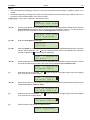
Entering decimal values
Press suitable keys to enter digits. Use the X key to move the cursor to the right, and the W
key – to move the cursor to the left. Use the S key to delete the character before the cursor.
Entering names
Press the particular keys until the required character appears. The characters available in the
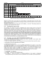
keypad are shown in Table 1. Hold down the key to display the digit assigned to the key.
INTEGRA
Key
1
2
3
4
5
6
7
8
9
0
SATEL
!
a
d
g
j
m
p
t
w
?
b
e
h
k
n
q
u
x
.
'
c
f
i
l
o
r
v
y
,
`
2
3
4
5
6
s
15
Characters available after next keystroke
"
{
}
$ % & @ \
^
|
#
1
]
0
7
8
z
:
9
;
+
-
/
=
_
<
>
(
)
[
Table 1. Characters available when entering names. The lower case letters are available
under the same keys (to change the letter case, press T key).
Shown on the left side in the upper line of the display is information about the letter case:
[ABC] or [abc] (it will be displayed after pressing any key and will be visible for a few seconds
after the last keystroke).
The X key moves the cursor to the right, and the W key – to the left. The S key deletes the
character on the left side of the cursor.
6.1.5 Reading alarm source name
The installer can enable the function of displaying the name of alarm source on the LCD
keypad, without necessity of entering the code. In such a case, the partition or zone name is
displayed on the keypad screen when an alarm occurs. If there are a few alarm causes, you
may scroll through the zone names which caused the alarm, and the names of partitions
where the alarm is (or was) signaled. The W and X arrow keys allow viewing partition names
(if the alarm occurred in several partitions), while the S and T keys allow viewing the names
of zones which caused the alarm. These names (entered by the installer) are displayed
cyclically in the lower keypad screen line, in the order corresponding to the numbers of
zones/partitions in the system. To view the names of alarm sources when the alarm signaling
is over, press and hold down the corresponding arrow key.
6.1.6 Proximity card reader (INT-KLCDR-GR/INT-KLCDR-BL only)
The INT-KLCDR-GR/INT-KLCDR-BL keypads with built-in proximity card reader make
available a few extra functions, including:
• card code readout when the card is assigned to its user (functions: NEW USER, EDIT USER),
• performance of function specified by the installer,
• registering the guard round.
The keypad can respond to the card being briefly presented to the reader or to its being
presented and held for a few seconds (approx. 3 sec.). It is also possible to perform two
consecutive functions which are assigned to bringing the card closer and holding it at the
reader. This feature makes it possible, by a single use of the card, to perform rather
complicated functions which might be time-consuming when called from the keypad.
List of functions which can be called by using the proximity card:
1. no function – no response
2. as code * – enters the user functions menu
3. as code # – calls the function of selecting partitions to be armed or disarmed
(arming/disarming if the selection list for the particular code is limited to just one partition)
16
User Manual
INTEGRA
4.
5.
6.
7.
8.
as code Ç – performs function assigned to the arrow key (p. 46)
as code Å – performs function assigned to the arrow key
as code Æ – performs function assigned to the arrow key
as code È – performs function assigned to the arrow key
open door (entry) – controls the electromagnetic door lock (generates a USER ACCESS
event)
9. open door (exit) – controls the electromagnetic door lock (generates a USER EXIT event)
10. 2 long sounds – signals reading of the card code
11. 1 short beep – signals that the card code has been read
Notes:
• Selecting the function 2 or 3 to be started by PRESENT CARD will block access to the HOLD
CARD.
• The 8 and 9 functions require that the installer select the door to be opened by the keypad.
It is possible to control any door handled by the system (i.e. opened by code locks,
partition keypads or expanders of proximity card readers).
• Two long beeps can also mean readout of a card with unknown code.
• Readout of an unknown (wrong) code, if repeated three times, may generate a panel
recorded event or an alarm PROG. It can also block the reader in the keypad for 90 sec.
6.2 PARTITION KEYPADS
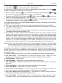
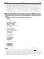
Fig. 4. INT-S-GR/INT-S-BL partition keypad.
INTEGRA
SATEL
17
SATEL offers the following partition keypads for INTEGRA control panels:
− INT-S-GR/INT-S-BL
− INT-SK-GR
These keypads differ by size and shape. The keypads are available with green or blue
backlighting of the keys. Designation of the models with green display ends with "GR" letters,
and that of the models with blue display – with "BL" letters. The backlighting may be
permanent or time-controlled (switched on automatically).
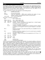
Fig. 5. INT-SK-GR partition keypad.
The partition keypads are provided with LED indicators:
-
(red) – permanent lighting of the LED means alarm. After the alarm time
expires, blinking of the LED indicates the alarm memory. The LED goes off after the
alarm is cleared (see: ALARMS).
ALARM
Note: The LED may not signal alarms in the armed mode if the installer has enabled the
option DO NOT SHOW ALARM IF ARMED, as required by the CLC/TS 50131-3 standard.
-
(green) – steady light indicates that the partition the keypad is assigned to, is
armed. Blinking indicates that exit delay countdown is underway.
- TROUBLE (yellow) – blinking indicates occurrence of a technical problem. The signaling
refers to the troubles from the entire alarm system, not only from the keypad controlled
partition. Check the LCD keypad for the type of trouble. The LED is off when the
partition controlled by the keypad is armed. Disarming will restore the trouble
signaling. The LED is blinking until troubles are viewed in the LCD keypad and the
trouble memory is reset (option TROUBLE MEMORY UNTIL REVIEW enabled) or until the
trouble cause stops (option TROUBLE MEMORY UNTIL REVIEW disabled) PROG.
ARMED
18
User Manual
INTEGRA
When all the LEDs are alternately blinking (from top to bottom), there is no communication
between the keypad and the control panel. This situation may occur when the STARTER
program is running in the control panel or the cable connecting the partition keypad to the
control panel is damaged.
It is possible to program the partition to be armed or disarmed after entering two codes
PROG. In this case, entering the first code causes the LEDs labeled
[ARMED] and
[TROUBLE] to blink alternately, while the control panel waits for entering the second code.
Like the LCD keypad, the partition keypad may generate audible signals:
• One short beep – acceptance of the code entry (provided that the option ACCES CODE
SIGNALING (HARDWARE) is enabled).
• One long beep – refusal of arming.
• Two long beeps – the code is unknown to the control panel.
• Two short beeps – acceptance of the first of two codes required for arming or disarming.
• Three long beeps – the code cannot control this partition.
• Three short beeps – confirmation of partition arming and disarming.
• Three pairs of short beeps – it is necessary to change the code – another user, when
changing his code, entered the identical combination of digits to that of the given user, or
the code validity period is expiring.
• Four short and one long beeps – confirmation of performance of a control function, code
change, or a guard round.
• Five short beeps – the dependent door is open – the door control has not been
performed. To operate the lock it is necessary to close the dependent door and reenter the
code.
The audible signaling may be substituted by the keypad illumination blinking PROG.
The beeps are consequently translated into the keypad extinguishing pulses, when the
backlighting is on, or illumination pulses, when the backlighting is normally off.
The partition keypad may also audibly indicate other situations PROG.
• Alarm in partition – continuous sound for the total alarm duration.
• Alarm memory – long beeps every two seconds until the alarm is reset. The sounds are
synchronized with the
[ALARM] LED blinking. Pressing any numeric key will mute the
signaling for approximately 40 seconds.
• Fire alarm – a series of long beeps every second for the total alarm duration.
• Fire alarm memory – short beeps every two seconds until the alarm is reset.
[ALARM] LED blinking. Pressing any numeric key
The sounds are synchronized with the
will mute the signaling for approximately 40 seconds.
• Countdown of entry delay – 2 short beeps every second.
• Countdown of exit delay – long beeps every 3 seconds, ended with a series of short
beeps (for 10 seconds) and a single long beep. This way of signaling the exit delay
indicates that the countdown is coming to an end before arming.
• Autoarming delay time countdown (timer-controlled partitions) – a series of 7 beeps
(of ever shorter duration).
• Door open too long – short beeps repeated with a high frequency until the door is
closed (with door control function activated).
• Chime in expander – five short beeps – information on violating selected zones in the
partition (CHIME option must be enabled in the partition keypad, and CHIME IN MODULE
option must be active for the zone).
Using the partition keypad you can control the armed mode in one partition and execute the
access control functions for a single door (door lock control).
INTEGRA
SATEL
19
Functions accessible from the keypad include:
[CODE][#] arming and disarming of partition; alarm clearing; and/or execution of control
function,
[CODE][*] control of module on-board relay (e.g. electromagnetic door lock opening) can
also be used for disarming (if the partition was armed, and the relay will not be
activated for the armed mode time) PROG.
Notes:
• If the given partition is armed, and the keypad is also used to operate the electromagnetic
door lock, then entering [CODE][*] will disarm the partition and open the door - unless the
partition is temporarily blocked.
• Entering [CODE][*] will not disarm the partition, if the option CODE + * DOES NOT DISARM is
enabled for the expander. Nevertheless, the door can be opened, if the option ACCESS IF
ARMED is enabled in the expander.
The user who wants to start the above mentioned functions must have access to the given
partition as well as appropriate authority level. In addition, he must be authorized to use the
given keypad by the master user or by the installer (service).
Note: Entering a wrong (not recognize) code three times may:
− trigger an alarm PROG;
− block a keypad for 90 sec. After this time each next wrong code entering will block
the keypad PROG.
Functions accessible from the partition keypad without entering the password:
− press in turn the [0] and [#] keys – fully armed mode;
− press in turn the [1] and [#] keys – enabling the fully armed mode and bypassing zones
with enabled BYPASSED IF NO EXIT option;
− press in turn the [2] and [#] keys – armed without interior mode (stay);
− press in turn the [3] and [#] keys – armed without interior and without entry delay mode
(stay, delay 0);
− press and hold down the
(INT-S-GR / INT-S-BL) or
(INT-SK-GR) keys for
approx. 3 seconds – FIRE alarm;
− press and hold down the
(INT-S-GR / INT-S-BL) or
(INT-SK-GR) keys for
approx. 3 seconds – AUX (medical) alarm;
(INT-S-GR / INT-S-BL) or
(INT-SK-GR) keys for
− press and hold down the
approx. 3 seconds – PANIC alarm.
Another function of the partition keypad is the option of code change by the user PROG.
The user code change is performed as follows:
1. Press and hold down (for approx. 3 seconds) the key with digit 1 (labeled
[ARMED] LEDs – red and green – start blinking alternately).
[ALARM] and
2. Enter the old CODE and press [#] (the
[ALARM] and
[TROUBLE] LEDs – red and
yellow – start blinking alternately).
3. Enter the new CODE and press [#] (the LEDs will stop blinking and the module will
generate a signal to confirm execution of the function).
The control panel cannot accept the change of code (which is signaled with two long beeps)
in the following four cases:
1. the new code is too short or too long (acceptable are codes 4 to 8 digits long);
2. the new code is too simple (the function of rejecting simple codes is activated);
3. the new code is identical with that of another user of the alarm system (someone else's
code was "hit"),
20
User Manual
INTEGRA
4. change of the code has been blocked because another user "hit" this code at an attempt
to change his own code. If the function of prompting about the necessity to change the
code is activated, each use of such a "hit" code will be signaled with three double beeps.
In such a case the change of the code will be only possible by means of the LCD keypad
– and confirmation of the code change will be required (see: description of the CHANGE
OWN CODE function) by the object master user. This feature makes impossible "capture" of
the code by a user who accidentally "hit" the code.
Note: With a large number of users it is advisable to use longer, at least 5-digit codes, to
reduce the chance of "hitting" another user's code. The CLC/TS 50131-3 standard
requires that 6-digit codes be used.
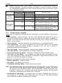
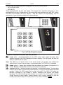
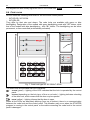
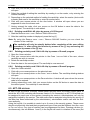
6.3 MULTIFUNCTIONAL KEYPAD WITH PROXIMITY CARD READER
The INT-SCR-BL multifunctional keypad with proximity
card reader can work as:
• partition keypad (see section: PARTITION KEYPADS);
• partition keypad with proximity card reader
- having the functionality of partition keypad,
enhanced by an option to identify users, based
on the proximity card;
• entry keypad – entering the access code
(password) or reading in the card will unlock the
time delay for interior delayed zones.
The keypad design enables it to be installed outdoors.
Additionally, the device is fitted with a bell button.
The keypad has two LEDs which are intended for
signaling:
- ALARM (red color),
- ARMED (green color),
- TROUBLE (yellow color).
Information conveyed with the LEDs depends on the
keypad operating mode. Blinking of all the LEDs in
turn (from left to right) indicates that there is no
communication with the control panel. Such a situation
may take place when the STARTER program is
running in the control panel, or the connecting cable
between keypad and control panel is defective.
6.3.1
Operation in partition keypad mode
(INT-S/SK)
The proximity card reader is not supported in this
mode. Information conveyed by means of the LEDs,
audible signaling and functionality have been
described in section PARTITION KEYPADS.
Note: In order to trigger the fire alarm, press and hold
key for approx. 3 seconds, and to
down the
trigger the PANIC alarm, press and hold down
the
key for approx. 3 seconds.
Fig. 6. Multifunctional keypad
INT-SCR-BL.
INTEGRA
SATEL
21
6.3.2 Operation in partition keypad mode with proximity card reader (INT-SCR)
The device executes functions of the partition keypad, however it allows the users not only to
use the access code, but the proximity card as well. Presenting the card is read out in much
the same way as entering the access code and confirming it by the
key. Holding the card
(for approx. 3s) is recognized as entering the access code and confirming it by the
key.
Note: Entering an invalid access code (i.e. unknown to the control panel) or placing
an unknown card in proximity may:
− trigger the alarm PROG;
− block the keypad for 90 seconds. After the blocking time has expired, entering
another invalid access code / reading in an unknown card will each time block the
keypad PROG.
Functions executed after entering the access code and confirming it with the
key or
presenting the card (the function to be executed depends on the user authority level, keypad
settings and security system status):
– relay activation
– disarming
– clearing alarm
– 24. MONO SWITCH output control
– 25. BI SWITCH output control
– guard round confirmation
– enabling temporary partition blocking
Note: Most of the abovementioned functions is available after enabling the LOCK [LOCK
FEATURE] option. Availability of the functions may also depend on other keypad options
(e.g. if the lock executes the ON IF PARTITION ARMED function, most of the operations
will be unavailable). None of these limitations refers to the functions executed after
entering the access code and confirming it with the
key or holding the card.
key or
Functions executed after entering the access code and confirming it with the
holding the card (the function to be executed depends on the user authority level, keypad
settings and security system status):
– arming
– disarming
– clearing alarm
– 24. MONO SWITCH output control
– 25. BI SWITCH output control
– guard round confirmation
– enabling temporary partition blocking
Functions accessible from the partition keypad without entering the password:
– press in turn the
and
keys – fully armed mode;
and
keys – enabling the fully armed mode and bypassing zones
– press in turn the
with enabled BYPASSED IF NO EXIT option;
– press in turn the
and
keys – armed without interior mode (stay);
– press in turn the
and
keys – armed without interior and without entry delay mode
(stay, delay 0);
key for about 3 seconds – FIRE alarm;
– hold down the
22
– hold down the
User Manual
INTEGRA
key for about 3 seconds – AUX (medical) alarm;
– hold down the
key for about 3 seconds – PANIC alarm.
Another function of the keypad is the option to change the access code by the user PROG.
In order to change the user code, do the following:
1. Press and hold down the
key for about 3 seconds (LEDs designated
[ALARM and ARMED] will start blinking alternately – red and green).
2. Enter the old ACCESS CODE and press
(LEDs designated
ARMED] will start blinking alternately – red and yellow).
and
and
[ALARM and
3. Enter the new ACCESS CODE and press
(the LEDs will stop blinking and the module
will generate a signal to confirm execution of the function).
The control panel may in four cases fail to accept the access code change (which will be
signaled by two long beeps):
1. The new access code is too short or too long (permissible length is from 4 to 8 digits),
2. The new access code is too simple (simple access code checking feature has been
started in the control panel),
3. The new access code is the same as that of another user of the security alarm system
(somebody else's password has been „hit”),
4. The change of access code has been blocked, because the code has been „hit" by
another user trying to change his own code. If the option to remind of the need to change
the code is enabled, each use of such a „hit" code will be signaled by three double beeps.
If this is the case, the access code change will only be possible by means of the LCD
keypad - with a necessary change confirmation (see description of the CHANGE OWN CODE
function) by the object administrator. This feature prevents the access code and its
authority from being „intercepted" by the user who accidentally has „hit” the password.
Note: In case of a large number of users, it is recommended that longer, at least 5-digit
access codes be used in order to reduce the probability of another user code being
„hit". The CLC/TS 50131-3 standard requires that 6-digit access codes be used.
Information conveyed by the keypad by means of the LED indicators has been described in
section PARTITION KEYPADS. Additionally, the keypad can signal by all the LEDs blinking
simultaneously that it is waiting for the card to be read in (during the procedure of adding
a card to the user).
The partition keypad with proximity card reader can generate the following audible signals:
• One short beep – acknowledgment of entering the access code / reading the card
(the ACCESS CODE SIGNALING (HARDWARE) option must be enabled by the installer).
• One long beep – refusal to arm.
• Two long beeps – access code / card unknown to the control panel.
• Two short beeps – acceptance of the first out of two access codes required for arming or
disarming.
• Three long beeps – access code / card cannot control the given partition.
• Three short beeps – confirmation of arming / disarming.
• Three pairs of short beeps – the user code needs to be changed (the NOTIFY OF
NECESSITY TO CHANGE ACCESS CODE option is enabled in the control panel).
• Four short beeps and one long beep – confirmation of control function execution,
change of access code, confirmation of guard rounds.
• Five short beeps – dependent door open – lock control has not been executed. In order
to operate the lock, close the dependent door and enter the code / read in the card again.
INTEGRA
SATEL
23
The audible signaling may be replaced by blinking of the keys backlight PROG. The beeps
will translate, respectively, into keypad backlight extinguishments – if the backlight is ON, or
into keypad backlight going on - if it is normally OFF.
The keypad can also signal other situations, as selected by the installer (see section
PARTITION KEYPADS).
6.3.3 Operation in entry keypad mode (INT-ENT)
The main task of the entry keypad is to unblock the delay for zones with reaction time
3. INTERIOR DELAYED. The time period during which these zones will act as delayed ones is
programmable for the keypad. If several entry keypads are assigned to one partition,
a different time of delay activation can be programmed for each of them. After the
programmed time period expires, the interior delayed zones will again act as instant ones.
The keypad will execute its functions after:
– entering the access code and confirming it with the
key,
– entering the access code and confirming it with the
key,
– presenting the card.
Additionally, the entry keypad may also execute the following functions:
– 24. MONO SWITCH output control
– 25. BI SWITCH output control
– guard round confirmation
The user who wants to run any function from the entry keypad must be authorized to use it
(the right is granted by the administrator or installer (service)). Except for the guard round
confirmation function, he must also have access to the given partition. Realized by the
keypad after entering the access code / presenting the card, the function depends on the
user authority level, keypad settings and security system status.
Note: Entering an invalid access code (i.e. unknown to the control panel) or placing an
unknown card in proximity may:
− trigger the alarm PROG;
− block the keypad for 90 seconds. After the blocking time has expired, entering
another invalid access code / reading in an unknown card will each time block the
keypad PROG.
In the entry keypad, only the LED designated
is used for signaling. Blinking of the LED
indicates that countdown of the delay activation time is running (disarming has no effect on
the LED blinking).
The entry keypad can generate the following audible signals:
• One short beep – confirmation of access code entry or card read-in (the ACCESS CODE
SIGNALING (HARDWARE) option must be enabled by the installer).
• Two long beeps – access code / card unknown to the control panel.
• Three long beeps – activation the delay is impossible (the partition is disarmed or the
delay has already been started) or the function is unavailable.
• Three short beeps – confirmation of delay activation.
• Three pairs of short beeps – the user code needs to be changed (the NOTIFY OF
NECESSITY TO CHANGE ACCESS CODE option is enabled in the control panel).
• Four short beeps and one long beep – confirmation of the guard round or execution of
the 24. MONO SWITCH or 25. BI SWITCH control function.
The audible signaling may be replaced by blinking of the keys backlight PROG. The beeps
will translate, respectively, into keypad backlight extinguishments – if the backlight is ON, or
into keypad backlight going on - if it is normally OFF.
24
User Manual
INTEGRA
The keypad can also audibly signal the DELAY ACTIVATION TIME PROG.
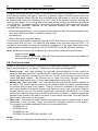
6.4 CODE LOCKS
SATEL offers the following code locks for the INTEGRA control panels:
− INT-SZ-GR / INT-SZ-BL
− INT-SZK-GR
They differ by their size and shape. The code locks are available with green or blue
backlighting. Designation of the models with green backlighting ends with "GR" letters, while
that of the models with blue backlighting – with "BL" letters. The backlighting can be either
permanent, or time-controlled (automatically activated).
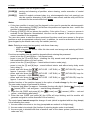
Fig. 7. Code lock type INT-SZ-GR/INT-SZ-BL.
The code locks are provided with LED indicators:
- ACTIVE (green) – lighting of the LED indicates that the lock is operated by the control
panel.
- ACCESS (depending on the lock type, of blue or red color) – lighting indicates unlocking
of the door lock, which means that the door may be opened.
- DOOR (yellow) – lighting informs that the door is open.
When all the LEDs are alternately blinking (from top to bottom), there is no communication
between the code lock and the control panel. This situation may occur when the STARTER
program is running in the control panel or the cable connecting the code lock to the control
panel is damaged.
INTEGRA
SATEL
25
Fig. 8. Code lock type INT-SZK-GR.
The basic function of the code lock is to control access to the room where the door provided
with electric catch, bolt or electromagnetic interlock is installed. The lock may also be used
for partition control during a guard round in the facility.
In order to open the door, enter the user CODE from the lock keypad and press [#] or [*].
The user must be authorized to use the particular code lock.
[CODE][#] door opening
[CODE][*] door opening
Note: Entering a wrong (not recognized) code three times may:
− trigger an alarm PROG;
− block a code lock for 90 seconds. After this time each next wrong code entering will
block the code lock PROG.
The code lock keypad can be used to change the user code, the change procedure being
the same as for the partition keypad.
The following special alarms can be quickly triggered from the code lock keypad:
− FIRE alarm – press and hold down the
(INT-SZ-GR / INT-SZ-BL) or
(INT-SZK-GR) key for approx. 3 seconds;
− AUX (medical) alarm – press and hold down the
(INT-SZ-GR / INT-SZ-BL) or
(INT-SZK-GR) key for approx. 3 seconds;
− PANIC alarm – press and hold down the
(INT-SZ-GR / INT-SZ-BL) or
(INT-SZK-GR) key for approx. 3 seconds.
Acknowledgement of acceptance by the control panel of the called control function (by sound
or illumination of the code lock keypad) is identical as for the partition keypad..
26
User Manual
INTEGRA
6.5 PROXIMITY CARD AND DALLAS CHIP READER
Using the card/chips activates control in the partition the reader is assigned to - in much the
same way as entering this type of code from a partition keypad. Presenting the card to the
reader/touching the reader with the chip is recognized by the reader in much the same way
as entering the code and confirming it by the [*] key in the partition keypad. Holding the
card/chip (for approx. 3s) is recognized in the same way as entering the code and confirming
it by the [#] key. The reader reaction to presenting the card/touching the reader with the chip,
or holding the card/chip, depends on the expander settings. By using the proximity
card/DALLAS chip you can:
− control the expander relay, and, by means of the expander relay, the electromagnetic door
lock, latch, lighting, actuators (ventilation, pumps, etc.);
− arm partitions;
− disarm the system and clear alarms.
The proximity card readers come with two-color LED and buzzer for communication of the
control panel with the user. The DALLAS chip heads come only with two-color LED. It is
possible for the installer to provide an additional signaling out of the head. Description of the
reader acoustic and optical signaling - see the CA-64 DR, CA-64 SR expander manuals.
Note: Reading in a wrong (not recognized by control panel) card/chip three times may:
− trigger an alarm PROG;
− block a reader for 90 seconds. After this time each next wrong card /chip reading in
will block the keypad reader PROG.
6.6 CODES AND USERS
Access to the control functions of the panel is possible after entering a proper code (4 to 8
digits) and pressing the [*] or [#] key. Three basic code types are distinguished:
1. Service code – this code identifies the user with special authority: he can control all
partitions and open all doors controlled by the control panel; he has access to most of the
control panel functions (except for the SERVICE ACCESS, VIEW MASTERS, CHANGE PREFIX,
USERS and some options – see DESCRIPTION OF USER FUNCTIONS), and may enter and
delete the object master users. Factory preprogrammed service code: 12345.
2. Master user (supervisor) code – this code identifies the user with the highest authority in
the object. The master user has access to all partitions within his object and determines
the service code access to the system. There is a function, available to the maser user
only, which enables the service access (see DESCRIPTION OF USER FUNCTIONS: SERVICE
ACCESS, CHANGE OPTION). The default master user code for the first object is 1111. Other
master user authority levels may be limited by the service (installer). If several objects are
defined in the system, each object can have its own master user code. This user has the
right to enter new users into the system.
3. User code – the remaining codes entered in the system by service, master users or users
(authorized to edit the user). These are codes for everyday operation of the system.
The number of available codes depends on the control panel size:
– INTEGRA 24: 16
– INTEGRA 32: 64
– INTEGRA 64: 192
– INTEGRA 128 and INTEGRA 128-WRL: 240
Notes:
• The installer can impose the minimal length of codes used in the system.
INTEGRA
SATEL
27
• The service can add, edit and delete the object users, provided that the SERVICE CAN EDIT
option has been enabled by the master user (administrator).
• Each user of the system (except for the master) can have a telephone code assigned to
him – see section ANSWERING PHONE CALLS.
• Service code is rejected by the control panel when the service access is disabled. The
rules of the service access to the alarm system are defined by the administrator.
• If there is no master user code in the system (all master users are removed), the service
access to the system is unlimited.
• It is recommended that the master user code not to used everyday (due to possibility of
unauthorized capture). The master user should enter for himself an ordinary user code,
with “strategic" functions disabled, and he should use it for everyday work. The main
reason for this is to protect access to the service mode and prevent entering codes by
unauthorized persons.
Additionally, a code can be assigned a specific control function which will be executed after
entering the code and pressing the [#] key (see: DESCRIPTION OF USER FUNCTIONS ÆUSERS) or
after using the proximity card assigned to the given code.
The installer (using the service code) grants codes and names to the master users (one
master user per each object), as well as he defines their rights.
The service and the master user have the right to enter ordinary system users. They grant
them the authority, type and define the partitions, to which the users will have access. Also,
the ordinary user may be authorized to enter new users. The new user may only have access
to the functions and partitions which are accessible to the user who enters the new code.
Note: If the entered user is authorized to change the code, he should change it after the first
use of his code. The control panel reminds the user to perform this operation by
means of a prompt on the keypad display and an audible signal PROG.
The system saves the order in which the users are entered. The person authorized to enter
and delete the users may only remove from the control panel memory the users entered by
himself or by his subordinates. The service has the right to edit all master users (as well as to
change their codes). The master user can edit and delete all users of his object. This also
applies to the service, provided that the master user has authorized the service to manage
the users in his partition. Ordinary users have authority to edit the users they entered
themselves. This is quite convenient in case the code is lost. The supervisor of the user
concerned may enter a new code and assign it the possibility to control the system
(of course, within the range limited by the authority).
The control panel assigns a number to the users to identify them in the system. This number
is used in messages transmitted to the monitoring station and in event descriptions
(see: DESCRIPTION OF USER FUNCTIONS ÆEVENTS).
Further information on entering new users or editing the existing users can be found in
description of the USERS function (page 47).
6.7 PREFIXES
In extended systems, which require an enhanced security level, the codes used are
sometimes composed of two parts: one which is periodically changed by the master user
(prefix) and the other which is determined by the user (user code). This ensures a periodic
change of the system access codes, while the users do not have to change their codes
individually. The prefix length (from 1 to 8 digits) is determined by the installer. Two kinds of
prefixes are used in the system:
− normal – for everyday use. By default, it consists of a suitable number of digits 0 (e.g. if
the determined prefix length is 4, the default prefix is 0000);
28
User Manual
INTEGRA
− DURESS – used in an emergency situation, when the user has been forced to enter the
code. Using the code will trigger a silent alarm. By default, the DURESS prefix consists of
a suitable number of digits 4 (e.g. if the determined prefix length is 3, the default prefix is
444).
For security reasons, it is useful to periodically change the prefixes. The master user of the
object is authorized to change the prefixes and define the change RECALL TIME (see function
ÆCHANGE PREFIX).
Notes!
• Changing the length of prefixes is possible only from the real keypads.
• Changing the length of prefixes by the installer restores their default values.
6.8 PROXIMITY CARDS/DALLAS CHIPS
The users of INTEGRA security alarm system (excluding the service) can be assigned
a proximity card and a DALLAS chip. The maser users can only be assigned a card / chip by
the service. The other users can be assigned a card / chip by the serviceman (if he has been
authorized to do so by the master user), master user or a user with the EDIT USER authority
level.
Note: The same card/chip cannot be assigned to two users.
6.8.1 Adding proximity card / DALLAS chip by means of LCD keypad
1. Start the NEW PROX. CARD / NEW DALLAS function.
2. Specify the reader (device with a reader) where the card/chip is to be read in, or select
entering the card/chip number manually.
3. Depending on the indicated method of card addition:
− read in the card/chip twice, following the prompts on the keypad display, and, after the
"Card read"/“DALLAS read" message is displayed, press [#];
− enter the card/chip number.
The card/chip will only be actually added after completion of the user adding /
editing procedure, i.e. after exiting the function by means of the [*] key and
saving the changes by means of the [1] key.
6.8.2 Adding proximity card / DALLAS chip by means of DLOADX program
1. Open the USERS window.
2. Click with your mouse pointer on the selected user.
3. Click with your mouse pointer on the CARD / DALLAS button. The card/chip adding window
will open.
4. Select the reader (device with a reader) to be used for reading in the card/chip.
5. Click with your mouse pointer on the ADD CARD / ADD DALLAS button.
6. According to the commands displayed in the window, read in the card/chip twice and,
after the CARD READ / DALLAS READ message appears, close the window.
7. Save the data to the control panel. The card/chip is now added.
Note: You can also add the card/chip by entering its number in the CARD / DALLAS field,
USERS window, and saving the data to the control panel.
6.8.3 Adding proximity card / DALLAS chip by means of GUARDX program
1. Open the USERS window.
2. Click with your mouse pointer on the selected user.
INTEGRA
SATEL
29
3. Click with your mouse pointer on the CARD / DALLAS button. The card/chip adding window
will open.
4. Select the method of adding the card/chip: by reading in on the reader, or by entering the
number manually.
5. Depending on the selected method of adding the card/chip, select the reader (device with
a reader) and read in the card/chip or enter its number twice.
6. Click with your mouse pointer on the ADD button. A window will open where you are
supposed to enter the access code.
7. Having entered the code, click your mouse on the OK button to save the data to the
control panel. The card/chip is now added.
6.8.4 Deleting cards/DALLAS chips by means of LCD keypad
1. Start the REMOVE PROX. CARD / REMOVE DALLAS function.
2. After the card/chip number is displayed, press the key [1].
Note: By using the REMOVE PROX.
number of the card/chip.
CARD
/ REMOVE DALLAS function you can check the
The card/chip will only be actually deleted after completion of the user editing
procedure, i.e. after exiting the function by means of the [*] key and saving the
changes by means of the [1] key.
6.8.5 Deleting proximity card / DALLAS chip by means of DLOADX program
1. Open the USERS window.
2. Click your mouse twice with the pointer in the CARD / DALLAS field of the user, whose
card/chip we wish to remove.
3. Delete the card/chip number.
4. Save the data to the control panel. The card/chip is now removed.
6.8.6 Deleting proximity card / DALLAS chip by means of GUARDX program
1. Open the USERS window.
2. Click with your mouse pointer on the selected user.
3. Click with your mouse pointer on the CARD / DALLAS button. The card/chip deleting window
will open.
4. Click with your mouse pointer on the DELETE button. A window will open where the access
code is to be entered.
5. Having entered the code, click your mouse button on the OK button to save the data to
the control panel. The card/chip is now deleted.
6.9 APT-100 KEYFOBS
In case of the INTEGRA 128-WRL control panel and any other INTEGRA control panel to
which the ACU-100 controller with firmware version 2.0 is connected, an APT-100 keyfob can
be assigned to each user of the system (excepting the service). Administrators can only be
assigned a keyfob by the service. The other users can be assigned a keyfob by the service (if
the latter has been authorized by the administrator), administrator and/or user with the EDIT
USER authority.
Using the keyfob, it is possible to control up to 6 zones in the security system. These zones
should not physically exist and their programmed type of line must be different from NOT USED
or FOLLOW OUTPUT. Any type of reaction can be programmed for them. Pressing a button (or,
simultaneously, the two buttons 1 and 5) in the keyfob will result in violation of the zone (the
30
User Manual
INTEGRA
zone will be violated as long as the keyfob button is depressed) and a corresponding reaction
of the control panel. A button/combination of buttons can control one zone in the system.
Zones are assigned to buttons/combinations of buttons individually for each user.
On pressing any keyfob button (which does not have to control a system zone), information
on the status of three selected system outputs will be presented for a few seconds on the
keyfob LEDs. Thus you can get confirmation of the function execution or information on the
current status of the system. The outputs on which the status is presented by means of the
keyfob LEDs do not have to physically exist. Up to 8 system outputs can be used for
providing information to the keyfob users.
Pressing any button/combination of buttons in the keyfob can generate an event informing
that a keyfob has been used. Generating such events can be enabled or disabled, so as to
reduce the number of events in the system.
Note: Dependencies between the keyfob buttons and the security system zones, as defined
for the user, will not be reset after the keyfob is removed (the only exception being the
REMOVE ABAX KEYFOB function, available in the service menu of LCD keypad). After
a new keyfob is added to the user, the buttons will control exactly the same zones, as
the buttons of the removed keyfob.
You can add the keyfob by entering its serial number manually or reading the serial number
during transmission which is sent after the button is pressed.
Note: The same keyfob cannot be assigned to two users.
The keyfob data are stored by the ABAX system (i.e. the wireless system of the mainboard of
INTEGRA 128-WRL control panel or the ACU-100 controller with firmware version 2.0 or
later). Connecting the ACU-100 controller with keyfob data to the INTEGRA 24,
INTEGRA 32, INTEGRA 64 or INTEGRA 128 control panel will result in keyfobs being
automatically assigned to the users of that control panel. This only applies to the users who
have already been created.
In case of LCD keypad, the keyfob will be added to / removed from the system,
the zones will only be assigned to the buttons, the outputs to the LEDs, etc.
after completion of the function of adding/editing administrator or user, i.e. after
exiting the function with the [*] key and saving the introduced changes by
pressing the key [1].
In case of DloadX program, the keyfob will be added to / removed from the
system, the zones will only be assigned to the buttons, the outputs to the LEDs,
etc. after the data are saved into the ABAX system (INTEGRA 128-WRL control
panel mainboard and ACU-100 controllers). In case of the INTEGRA 128-WRL
control panel, click your mouse on the
button. In case of the other control
panels, click on the Write button in the ABAX Keyfobs window.
6.9.1 Adding keyfob by means of LCD keypad
Adding of the ke fobs is possible owing to the NEW ABAX KEYFOB function ([service code][*]
ÆMASTERS ÆNEW MASTER/EDIT MASTER ÆNEW ABAX KEYFOB or [code][*] ÆUSERS ÆNEW
USER/EDIT USER ÆNEW ABAX KEYFOB).
Entering the serial number manually
1. Select ENTER MANUALLY from the list.
2. Enter the keyfob number and press the [#] key.
INTEGRA
SATEL
31
Reading the serial number during transmission
1. Select from the list the device which is to receive the transmission containing serial
number (depending on configuration, this can be mainboard of INTEGRA 128-WRL
control panel or ACU-100 controller).
2. Following the prompts displayed on the keypad, press the keyfob button twice, and after
the message KEYFOB READ appears press the [#] key.
6.9.2 Adding keyfob by means of DLOADX program
Adding the keyfobs is possible in the ABAX KEYFOBS window. To open the window, click your
mouse on the ABAX KEYFOBS item in the USERS menu.
In case of the INTEGRA 128-WRL control panel, the keyfob data will be displayed
automatically. These will be the data of the mainboard ABAX system (the program will not be
able to read the data from ACU-100 controllers connected to the INTEGRA 128-WRL control
panel). In case of the other control panels, it is necessary that the keyfob data be read before
the attempt of adding a new keyfob. For this purpose, click on the READ button. The program
will read data from the lowest address ACU-100 controller with keyfob support. The name(s)
of controller(s) (displayed at the top of the window) with which the control panel can
communicate will be highlighted in green (the names of controllers which cannot support
keyfobs will be highlighted in yellow).
In order to make the keyfob data uniform in all controllers, e.g. when connecting new
ACU-100 controllers to a system in which such controllers are already in operation, do the
following:
– in case of the INTEGRA 128-WRL control panel click on the WRITE TO ALL button
(the button is available when ACU-100 controllers with keyfob support are connected to
the control panel and no changes have been made to the keyfob data read from the
mainboard ABAX system);
– in case of the other control panels click on the WRITE button (before making any changes
to the read data).
Note: If there are several ACU-100 controllers working with the control panel and
communication with any of them is lost, saving the keyfob related data will not be
possible.
Entering the serial number manually
1. Click your mouse on the field in S/N column next to the name of user to whom you want
to assign a keyfob.
2. Enter the keyfob serial number and confirm with ENTER. The background color of the
field in which the serial number is shown will change to pink. After the data are written to
the ABAX system, thus ending the procedure, the background color will change to white.
Reading serial number during transmission
1. Click your mouse on the field in S/N column next to the name of user to whom you want
to assign a keyfob.
2. Click on the NEW button. The NEW window will open.
3. According to the prompt which will appear in the window, press the keyfob button and,
when the keyfob serial number is displayed in the window, press OK. The NEW window
will close and the keyfob serial number will be shown in the S/N column, next to the user
name. The background color of the field in which the serial number is shown will change
to pink. After the data are written to the ABAX system, thus ending the procedure, the
background color will change to white.
32
User Manual
INTEGRA
6.9.3 Removing keyfob by means of LCD keypad
1. Start the REMOVE ABAX KEYFOB function ([service code][*] ÆMASTERS ÆNEW MASTER/EDIT
MASTER ÆREM.ABAX KEYFOB or [code][*] ÆUSERS ÆNEW USER/EDIT USER ÆREM.ABAX
KEYFOB).
2. When the keyfob number is displayed, press the key [1].
6.9.4 Removing keyfob by means of DLOADX program
Removal of the keyfobs is possible by using the ABAX KEYFOBS window, after the keyfob data
have been read (see section: ADDING KEYFOB BY MEANS OF DLOADX PROGRAM).
1. Click your mouse on the field in S/N column next to the name of user whose keyfob you
want to remove.
2. Click on the DELETE button.
3. A window will open. Confirm your intention to remove the keyfob by clicking your mouse
on the YES button. The keyfob serial number will be deleted. The background color of the
field in which the serial number is shown will change to pink. After the data are written to
the ABAX system, thus ending the procedure, the background color will change to white.
6.9.5 Assigning zones to buttons by means of LCD keypad
Assigning zones to a button/combination of buttons is made possible by the functions
available when adding/editing administrator ([service code][*] ÆMASTERS ÆNEW MASTER/EDIT
ÆBUTTON 1/BUTTON 2/BUTTON 3/BUTTON 4/BUTTON 5/BUTTON 1 AND 5) or user
MASTER
([code][*] ÆUSERS ÆNEW USER/EDIT USER ÆBUTTON 1/BUTTON 2/BUTTON 3/BUTTON 4/
BUTTON 5/ BUTTON 1 AND 5).
1. Start the selected function.
2. Using the S andT keys, select a zone from the list or enter the zone number from the
keypad.
3. Press the [#] key.
A
B
Fig. 9. APT-100 keyfob. A – numeration of LEDs. B – numeration of keyfob buttons.
6.9.6 Assigning zones to buttons by means of DLOADX program
Assigning zones to keyfob buttons is possible in the ABAX KEYFOBS window after reading the
keyfob data (see section ADDING KEYFOB BY MEANS OF DLOADX PROGRAM).
INTEGRA
SATEL
33
1. Click at the selected user in the column corresponding to the button/combination of
buttons to which you want to assign the zone.
2. Using the keyboard, enter the number of zone which is to be controlled by the button, and
confirm by pressing ENTER. Part of the field in which the zone number is displayed will
change its color to pink. After the data are saved into the ABAX system, which completes
the procedure, the field background will change its color to white.
6.9.7 Assigning the outputs to the LEDs by means of LCD keypad
The installer must determine in the service mode which system outputs will be able to be
used for confirmation and information for the keyfob users. For this purpose, the ABAX
CONFIRMATION service function should be used (SERVICE MODE ¼STRUCTURE ¼HARDWARE
¼EXPANDERS ¼ABAX CONFIRMAT.).
After the list of outputs dedicated to confirmation and information for the keyfob users has
been defined, you can proceed to assigning the outputs to the LEDs. The assignment of
outputs to LEDs in the keyfob is made possible by the function available in the process of
adding/editing the administrator (master) ([installer code] [*] ÆMASTERS ÆNEW MASTER/EDIT
MASTER ÆCONFIRM. (ABAX)) lub użytkownika ([hasło][*] ÆUSERS ÆNEW USER/EDIT USER
ÆCONFIRM. (ABAX)).
6.9.8 Assigning the outputs to the LEDs by means of DLOADX program
Assignment of the outputs to the LEDs is possible in the ABAX KEYFOBS window after reading
the keyfob related data (see: ADDING KEYFOB BY MEANS OF DLOADX PROGRAM).
Before the outputs can be assigned to LEDs in the keyfob, you must define which system
outputs will be able to be used for this purpose:
1. Click on the first of the eight fields on the right-hand side of the window to display the list
of system outputs.
2. Select from the list the output whose status will be able to be presented on the keyfob
LEDs. The color of the field will change into pink.
3. Repeat the above steps for the next seven fields on the right-hand side of the window.
4. After all data have been saved to the ABAX system, the background color in all fields will
change into white.
After the list of outputs dedicated to confirmation and information for the keyfob users has
been defined, you can proceed to assigning the outputs to the LEDs:
1. Click at the selected user in the LED column.
2. Using the keyboard, enter up to 3 digits. The field color will change into pink. Each of the
digits corresponds to the number of the field with output selected for confirmation, i.e. can
be from the 1 to 8 range. The names of outputs in selected fields will be emboldened.
3. After the data have been saved to the ABAX system, the background color in the LED
column will change into white.
6.9.9 Configuring event generation rules by means of LCD keypad
Enabling/disabling generation of events for particular keyfob buttons is possible by using the
EVENTS (ABAX) function, which is available when adding/editing administrator ([service
code][*] ÆMASTERS ÆNEW MASTER/EDIT MASTER ÆEVENTS (ABAX)) or user ([code][*]
ÆUSERS ÆNEW USER/EDIT USER ÆEVENTS (ABAX)). To enable/disable the event generation
feature, press any numerical key. Event generation for the given button is enabled, when the
symbol is displayed in the upper line.
34
User Manual
INTEGRA
6.9.10 Configuring event generation rules by means of DLOADX program
Enabling/disabling generation of events for particular keyfob buttons is possible by using the
ABAX KEYFOBS window, after the keyfob data have been read (see section ADDING KEYFOB BY
MEANS OF DLOADX PROGRAM).
1. Click at the selected user in the column corresponding to the button/combination of
buttons for which you want to enable/disable the generation of events.
2. Using the SPACE button, enable/disable the event generation feature. The event
generation for the given button is disabled, if the 8 symbol is shown next to the number of
zone controlled by the button (lack of the symbol means that the event generation is
enabled). Any modification of the settings will change the background color in part of the
field next to the zone number into pink. After the data are saved into the ABAX system,
which completes the procedure, the field background will change its color to white.
6.10 SYSTEM ARMED MODE
The control panel performs its facility protection functions primarily when the system is
armed. When in the armed mode, any change of the zone state to another one, different from
that defined for the normal state (e.g. as a result of motion being detected by the detector,
opening the reed switch contacts after opening the window or door, etc.), will trigger
a reaction programmed by the installer (e.g. activate sirens, report the event to monitoring
station, etc.).
The user can arm the system using one of the following ways:
• entering [CODE][#] in LCD keypad – all partitions or some selected partitions only can
be armed;
• entering [CODE][#] in partition keypad – the partition to which the keypad is assigned
can be armed;
• entering [CODE][*] in LCD keypad and choosing ARM function – selected partitions
can be armed; if any of the partitions controlled by the keypad is armed, this is the only
way to arm of the other partitions;
• entering [0][#] in LCD keypad – all installer programmed partitions will be armed;
• entering [0][#] in partition keypad – the partition to which the keypad is assigned will be
armed;
• presenting and holding the card in face of the reader until the selected LED in
INT-CR proximity card arm/disarm device comes on – the partitions assigned to the
given LED by the installer will be armed;
• holding card in the proximity of the reader for approximately 3 seconds – the
partition to which the reader is assigned will be armed;
• holding DALLAS chip in the reader for approximately 3 seconds – the partition to
which the reader is assigned will be armed.
Notes:
• The control panel will not arm the partition(s) in the following cases:
− at least one zone with active PRIORITY option is violated in the selected partition;
− the options REQUIRED SYSTEM RESET AFTER VERIFIED ALARM, DO NOT ARM IF TAMPER, DO
NOT ARM IF BATTERY TROUBLE, DO NOT ARM IF TROUBLE, DO NOT ARM IF OUTPUTS TROUBLE
and DO NOT ARM IF REPORTING TROUBLE are enabled and at least one of such situations
takes place.
In case of arming by means of the LCD keypad, a list of causes which prevent arming will
be displayed. Press the [*] key to cancel the arming. Press the [#] key to repeat the
attempt of arming (without having to select partitions or armed mode status). If the cause
INTEGRA
SATEL
35
which prevented arming has been in the meantime removed, the partition will be armed.
Otherwise, the list of causes which prevent arming will be displayed again.
• If the SERVICE MESSAGE AFTER TAMPER ALARM and DO NOT ARM IF TAMPERED options are
enabled by the installer, the arming will only be possible after repairing the tamper and
clearing the message by using the service code.
• If the arming by means of the LCD keypad is impossible because:
– a zone with enabled PRIORITY option is violated;
– the DO NOT ARM IF TAMPERED option is enabled and the zone is tampered (type 2EOL
zone, too long violation of the zone or too long non-violation of the zone),
you can bypass the selected zone by pressing the key [4] during review of the causes
which prevent arming. Bypassing is possible when the user has a suitable authority level,
and the installer has allowed the zone to be bypassed (the BYPASS DISABLED option is not
enabled for the zone).
• If the option WARN WHILE ARMING IF TROUBLE is enabled, the partitions are armed from the
LCD keypad and there are troubles in the system, the control panel will inform the user of
it with a suitable message before arming. Pressing the key [1] will arm the partition(s), and
pressing the key [2] will display information on troubles. Pressing the [*] key will make it
possible to cancel the arming and trouble review. If the key [2] was pressed, there will be
return to the question about arming or trouble viewing after the review is completed and
the [*] key is pressed.
• If the arming is performed by means of the LCD keypad in a partition with temporary
blocking, the control panel will ask to indicate the block time before arming.
• If the option VIOLATED/BYPASSED ZONE PREVIEW WHEN ARMING is active and the arming is
performed from the LCD keypad, the control panel will check that there are no
violated/bypassed zones. Checked for possible violation are the zones for which the
PRIORITY option has not been enabled. If violated or bypassed zones are found, the
following message will be displayed on the keypad: "Viol./Bypass z. 1=Arm 2=Check".
Pressing the key [1] will arm the partition, and pressing the key [2] will display information
on violated/bypassed zones. The [*] key will cancel the arming and viewing. If the key [2] is
pressed, the question about arming and viewing will be asked again after completion of the
viewing and pressing of the [*] key.
In case of zones for which the exit delay time has been programmed, the arming will take
place after the countdown ends. It is possible to terminate the exit delay countdown and arm
the partition immediately by entering [9][#] from the keypad or partition keypad PROG.
Reduction of the exit time is only possible on the same keypad/partition keypad from which
the arming was done.
A special armed mode can be enabled in the partition to allow the user to stay in the facility
where the system has been armed:
– full arm with bypass – the zones with enabled BYPASSED IF NO EXIT function will be
bypassed, i.e. the control panel will not respond to their violation. Otherwise, the facility is
normally protected.
– armed without interior – the control panel will not react to violation of the interior zones
(zone type 3. INTERIOR DELAYED). The exterior zones (zone type 8. EXTERIOR) will trigger
silent alarm. Otherwise, the facility is normally protected and all functions are executed.
– armed without interior and without entry delay – the control panel will react in the
same way as above, but, additionally, the delayed zones (zone type: 0. ENTRY/EXIT,
1. ENTRY, 2. DELAYED WITH DELAY SIGNALING) will act as instant ones.
In order to enable the special armed mode by means of LCD keypad, do the following:
1. Enter ACCESS CODE and press the [*] key.
36
User Manual
INTEGRA
2. Call the ARMING MODE function.
3. Using the S and T keys select one of the suggested arming modes and press [#].
4. Call the ARM function and select (highlight) the partition to be armed.
5. Press the [#] key.
In order to re-enable the special armed mode, the above procedure must be repeated.
If the function of quick arming without code entry has been made available by the service in
LCD keypad /partition keypad, you can enable the special armed mode by successively
pressing the keys:
[1] and [#] – full arm with bypass;
[2] and [#] – armed without interior;
[3] and [#] – armed without interior and without entry delay.
The procedure of arming the system from a LCD keypad in the partition to which the type
(10) 24H VIBRATION zone belongs and the testing function of vibration sensors is activated
PROG is somewhat different.
When the arming function is called, the following message appears on the LCD display:
"Vibr. zone test xx s (1=arm)" where the xx field indicates the number of seconds before the
end of test.
During the test, the control panel is waiting for the violation of vibration zones in a given
partition. If all the vibration zones of the given zone are violated, the alarm control panel will
proceed to counting the exit delay time and arming the system. If any of the vibration zones is
not violated during this time, the control panel will display a list of faulty zones (number and
name of zone) and will not arm the system.
Pressing the digit 1 key during the process of countdown will interrupt the test and arm the
system in normal mode, while pressing the [*] key will make it possible to cancel the arming.
Arming the system from the partition keypad will bypass the testing of vibration sensors in the
particular partition.
The user can disarm the system using one of the following ways:
• entering [CODE][#] in LCD keypad – all partitions or some selected partitions only can
be disarmed;
• entering [CODE][*] or [CODE][#] in partition keypad – the partition to which the keypad
is assigned can be disarmed;
• entering [CODE][*] in LCD keypad and choosing DISARM function – selected partitions
can be disarmed;
• bringing the card closer to the INT-CR proximity card arm/disarm device and
moving it away after approx. 0.5 second – all partitions operated by the module will be
disarmed;
• bringing closer or holding card in the proximity of the reader (depending on
expander settings) – the partition to which the reader is assigned will be disarmed;
• bringing closer or holding DALLAS chip in the reader (depending on expander
settings) – the partition to which the reader is assigned will be disarmed.
Also, special control ways of partition status are possible:
• partition arming and disarming by means of timers. The timer is an internal control panel
logic unit which measures time. Timer operation is programmed by the service;
• partition arming and disarming by the “partition user timer". Operation of this timer may be
programmed by the partition user, without having the installer (or the service) to do the job.
There is a single partition timer of this type, which can be programmed in daily or weekly
cycle (see: DESCRIPTION OF USER FUNCTIONS ÆCHANGE OPTIONS);
INTEGRA
SATEL
37
Note: The special armed modes, as described earlier, are also defined for timers.
• partition arming control by means of a special zone programmed (by the installer) as
arming control zone. In practice, it may be a mechanical switch; key switch, pushbutton,
radio switch. It is also possible to control such a zone by means of the REMOTE SWITCH
type output (see: ANSWERING PHONE CALL). Disarming by means of the zone can also clear
the alarm and telephone messaging;
Note: The zone will arm always, unless the option CHECK ARM POSSIBILITY is enabled. If this is
the case, all the conditions which make arming impossible (see page 34) will be taken
into consideration.
• arming/disarming by the use of code and arrow keys (see: USE OF LCD
mode facilitates access to the above mentioned "special ways of arming".
KEYPAD)
– this
6.11 ALARMS
The system may signal alarms as the response to various situations that occurred in the
protected facility. The basic control panel alarms include:
Burglary alarm – activated when the zone is violated in the partition where arming is on.
Violation of the “delayed zone" starts countdown of the delay time, after expiry of which
an alarm is activated unless the partition is disarmed.
Fire alarm – activated by fire detectors, from keypad or otherwise (e.g., by pressing
pushbutton).
Tamper alarm – activated by violation of any tamper contacts in the alarm system (located in
detector and module casings), damage to cables, etc.
Panic alarm – activated from keypad or otherwise as defined by the installer (e.g., by
pressing pushbutton).
Auxiliary alarm – activated from keypad (for example, call for medical aid) or otherwise as
defined by the installer (e.g., remote controller or pushbutton).
Technical alarm – activated by various specialist detectors.
The way of signaling individual alarms may be different, as defined by the system installer. It
may be an alarm siren, information to the monitoring station, visual alarm, audible alarm
and/or keypad message, telephone message, activation of other external devices.
The alarm can be cleared by a user authorized to clear alarms in the given partition/object.
The alarm will be cleared after entering the code and confirming it with the [#] key. If the user
is authorized to disarm the partition, the alarm clearance will be accompanied by disarming.
The disarming will not be effected automatically, if the user may disarm more than one
partition. He must then chose the partitions to be disarmed. He can also cancel the disarming
by pressing the [*] key. In order to clear the alarm without disarming the partition, it is
possible to use the user function CLEAR ALARM.
Immediately after the alarm is cleared, viewing of the violated zones is possible. If the user
decides not to view them immediately, he can do it at a later date by means of the user
option VIEW CLEARED ALARMS. The function will be available in the user menu until the viewing
is done.
6.12 ALARM MESSAGING BY TELEPHONE
All the INTEGRA series control panels can inform about events in the system by means of
voice messages (connection of voice synthesizer is required), as well as PAGER type text
messages. The INTEGRA 128-WRL control panel can additionally notify by means of SMS
type messages. The SATEL made GSM modules offer the feature of converting the PAGER
38
User Manual
INTEGRA
messages into SMS messages, thus allowing the use of this form of notifying also in the
other INTEGRA control panels.
The number of telephones to which the messaging is effected, and the number of available
voice messages or text messages, depends on the control panel size.
In case of notifying by a voice message, the control panel settings may require confirmation
(acknowledgement) that the message has been listened to. If there is no such confirmation,
the control panel can make further attempts to connect and play back the message.
The number of redials and the confirmation rules (code) are defined by the installer.
A telephone with DTMF tone dialing must be used for the confirmation.
If the entered code is wrong, the control panel will signal the fact with two long tones (beeps).
Correct code is confirmed by four short and one long beeps. If a single short beep is heard
every three seconds instead of the above mentioned signals, the code is correct but you
must wait, because there are several messages regarding different alarms.
If you make a mistake when entering the code, press any numeric key to supplement the
code to four digits (then the control panel will signal a wrong code), and then re-enter the
correct code.
Notes:
• The control panel analyzes telephone signals in order to recognize whether the call is
answered. Therefore, it may occur that you will hear the message after few seconds (up to
4 seconds) from picking the handset. This is not an error – the effect is a result of the
phone call-back signal. When you say "hallo..." to the handset, the message will be
reproduced immediately.
• Acknowledgement of message reception by the user can reset the function of messaging
to other users PROG.
• If no confirmation rules for having listened to the message are defined in the control panel
by the installer, the control panel will recognize reception of the message as confirmed,
when the receiver is lifted after two rings and any sound occurs.
6.13 ANSWERING PHONE CALLS
The users having a telephone code (not to be confused with the acknowledgement code for
receipt of a telephone message) can use the call answering and telephone control functions.
The call answering function allows to obtain information on the state of partitions (armed,
alarms) to which the given user has access. Owing to the telephone control function, the
users with a telephone code can control the REMOTE SWITCH outputs. The installer defines
which switches can be controlled by the given user. The call answering and telephone control
functions require that a telephone with DTMF tone dialing be used.
Note: Not all cellular telephones allow control in DTMF tone system.
How to use this function:
• Dial the telephone number (line) of the control panel. The method of dialing is defined by
the installer. The control panel may establish connection after a defined number of dialing
signals (rings). The dialing can be single or double. When double dialing is used, wait until
a defined number of “rings" is completed, put the handset off, and then dial the control
panel telephone number again. After the number is dialed the second time, the control
panel should answer immediately.
• After the connection is established, the control panel is ready to receive the user telephone
code – three short beeps (handshake).
• Enter the code from the telephone keypad (in tone system). The control panel will
acknowledge the correct code with a series consisting of four short and one long beeps.
INTEGRA
•
•
•
•
•
•
•
SATEL
39
Two long beeps follow receipt of an incorrect code. If the entered code is invalid, the
control panel will signal it by two long beeps and will not be answering any calls for the
next 4 minutes.
The control panel is in partition status information mode. It waits for user’s response for 15
seconds, generating one short beep every two seconds. You are expected to enter the
partition number from the telephone keypad (in two-digit format, e.g., 01; 05; 12; 25).
If there is no response within this time, the control panel will ring off.
After the partition number is entered, the control panel generates the message. Three
short beeps inform that the partition is disarmed and four short and one long beeps mean
that the partition is armed.
Alarm memory is the extra information given by the control panel. If an alarm occurred in
the partition, the control panel generates a series of double beeps – one lower and the
other higher – following the partition status information. If there was no alarm, the control
panel will generate a single short beep every two seconds.
In order to proceed to the control of the remote switches status, press [2] and [#] on the
telephone keypad. After the control function is entered, a periodic signal in the form of two
short beeps can be heard in the receiver.
Now the control panel waits for the (two-digit) switch number to be entered. Entering the
telephone number from the telephone keypad will switch the relay status to the opposite
one. Three short beeps mean that the relay is switched off and four short and one long
beeps - that the relay is switched on. Each time you enter the same number, the relay
status is changed to the opposite one.
It is possible to move back to the partition status indication mode by pressing in turn the [1]
and [#] keys.
Pressing in turn the [0] and [#] keys will exit the function and terminate the telephone
connection.
6.14 OTHER FUNCTIONS USING TELEPHONE LINE
If functions of the control panel telephone communicator are used in the alarm system, then
the facility public line should be directly connected to the control panel, and all telephone sets
should be installed after the control panel. Therefore, no signals are heard in telephones
connected after the control panel, when the panel is on the telephone line. This situation may
frequently occur in multi-partition systems, when monitoring is activated (a special reporting
system intended for sending information on the object status to a security agency, working
independently of the aforementioned user notification system). Moreover, the control panel
will disconnect telephone conversations to capture the telephone line in order to transmit an
information on a new event. It should be noted that such connections do not last very long
(from a few seconds to one minute, depending on the selected format of data transmission).
Another function, when the control panel occupies the telephone line, is programming by
telephone (“downloading"). The service may initialize this function by phone. During data
interchange with the service computer, the telephone line may be occupied for a long time.
Even if the programming is initialized by the user, the service may suspend communication
with the control panel to reduce the connection costs, and then resume it without involvement
of the user.
Notes:
• The downloading function will be automatically stopped, if 255 minutes have elapsed since
the last use of the DLOADX program, and the service access was blocked or expired in the
meantime.
40
User Manual
INTEGRA
• The control panel is protected against any attempts to scan the code – after three
consecutive attempts to get access to the panel using wrong codes within one telephone
communication session, the function of answering the modem signals will be disabled for
30 minutes.
6.15 SMS CONTROL ONLY INTEGRA 128-WRL
The INTEGRA 128-WRL control panel makes available to the users the function of control by
SMS messages. Receiving by the control panel of a message containing appropriate
command may result in violation of a zone, launching of a selected function or sending
a return message with information on the system status. Several control commands may be
included in one SMS message. The contents of the messages and additional rules for using
them (case sensitivity, adding the telephone code to the body of sent SMS message, etc.)
shall be defined by the installer.
7. USER FUNCTIONS
7.1 MAIN MENU
Presented on the next few pages is menu of all the user functions. These functions are made
available by the control panel in LCD keypad on entering the service code, master code or
normal user code and pressing the [#] or [*] key. Some of the specified functions are only
accessible to a selected code type. All details concerning the particular functions are
described hereunder. Function descriptions are arranged in the order corresponding to that of
the menu available on entering the [CODE][*].
7.1.1
User function menu
Note: As the menu changes dynamically, depending on the programmed system parameters
and the user authority level, not all functions are visible to the user.
[USER CODE][#] (calling the functions arming / disarming)
Disarm all
Disarm selected
[select partitions]
Arm all
Arm selected
[select partitions]
[USER CODE][*] (calling the user functions)
The functions available after entering the service code have been highlighted with white text
against black background. Highlighted with a frame are functions available to the
administrators. All functions are described in detail further in this manual.
View clear. al.
System reset
Disarm
Clear alarm
Clear other al.
Abort voice m.
Arm
Arm (2 codes)
Disarm (2codes)
view cleared alarms from selected partition zones
restore system after verified alarm
disarm selected partitions
clear alarm
clear alarm in other objects
cancel telephone messaging
arm selected partitions
start two code arming
start two code disarming
INTEGRA
SATEL
Defer auto-arm
postpone the auto-arming
Set auto-arm d.
set auto-arming postpone time
Arming mode
select arming mode
Cancel 1st code
cancel first code
Change own code
change own code
Change prefix
Prefix normal
set normally used prefix
Prefix duress
set duress prefix
Recall time
set time to remind of the need to change prefix
Users
New user
add new user
Code
set code
Telephone code
set telephone code
Partitions
assign partitions available to the user
Type
select type of code
select time schedule
Schedule
Existence time
set code validity time
Bypass time
set bypass time
Rights
assign rights
assign modules available to the user
Keypads etc.
New prox. card
add proximity card
Rem. prox. card
remove proximity card
add DALLAS chip
New DALLAS
Remove DALLAS
remove DALLAS chip
New RX keyfob
add keyfob supported by INT-RX module
Rem. RX keyfob
remove keyfob supported by INT-RX module
Button 1
assign function to keyfob button 1
assign function to keyfob button 2
Button 2
Button 3
assign function to keyfob button 3
Button 4
assign function to keyfob button 4
Button 1 and 2
assign function to combination of keyfob buttons 1 & 2
Button 1 and 3
assign function to combination of keyfob buttons 1 & 3
set event generating rules
Events (RX)
New ABAX keyfob
add keyfob supported by ABAX system
Rem.ABAX keyfob
remove keyfob supported by ABAX system
assign function to keyfob button 1
Button 1
Button 2
assign function to keyfob button 2
Button 3
assign function to keyfob button 3
Button 4
assign function to keyfob button 4
Button 5
assign function to keyfob button 5
Button 1 and 5
assign function to combination of keyfob buttons 1 & 5
Events (ABAX)
set event generating rules
Confirm. (ABAX)
set confirmation rules
program user name
Name
edit existing user
Edit user
[select user]
[list of parameters identical as in case of a new user]
remove user
Remove user
Masters
New master
add new master
Code
set code
Rights
assign rights
assign modules available to the master
Keypads etc.
41
42
User Manual
New prox. card
add proximity card
Rem. prox. card
remove proximity card
New DALLAS
add DALLAS chip
Remove DALLAS
remove DALLAS chip
New RX keyfob
add keyfob supported by INT-RX module
Rem. RX keyfob
remove keyfob supported by INT-RX module
Button 1
assign function to keyfob button 1
Button 2
assign function to keyfob button 2
Button 3
assign function to keyfob button 3
Button 4
assign function to keyfob button 4
Button 1 and 2
assign function to combination of keyfob buttons 1 & 2
Button 1 and 3
assign function to combination of keyfob buttons 1 & 3
Events (RX)
set event generating rules
New ABAX keyfob
add keyfob supported by ABAX system
remove keyfob supported by ABAX system
Rem.ABAX keyfob
Button 1
assign function keyfob button 1
Button 2
assign function keyfob button 2
Button 3
assign function keyfob button 3
Button 4
assign function keyfob button 4
Button 5
assign function keyfob button 5
Button 1 and 5
assign function to combination of keyfob buttons 1 & 5
Events (ABAX)
set event generating rules
set confirmation rules
Confirm. (ABAX)
Name
set master name
Edit master
edit existing master
[select master]
[list of parameters identical as in case of a new master]
remove master
Remove master
Zone bypasses
Inhibit
one-time zone bypass
Isolate
permanent zone bypass
set control panel clock
Set time
Troubles
view troubles
Events
Selected
Select events
select type of events to be viewed
Select part.
select partitions from which events are to be viewed
View
view selected events
view all events
All
Reset zones
reset type 43. RESETABLE POWER SUPPLY outputs
Clr.latch.outs
clear latched outputs
Fin.f.door open
end door fire opening
Change options
Keypad chime
enable/disable CHIME in keypad
Outputs chime
block zone violation signal. on type 11. CHIME outputs
Part. timers
program user timers
No exp.tamp.al.
block expander tampers
Perm.serv.accs.
enable/disable permanent service access
Serv. can edit
make user editing available to service
Serv. ArmDis...
make system control available to service
Perm.DloadX acc
enable/disable permanent DLOADX access
DloadX IP
set address of computer with DLOADX program
set address of computer with GUARDX program
GuardX IP
INTEGRA
INTEGRA
Erase s.message
Tests
Partitions
Zones
Supply voltage
Radio devices
Zones test
New
Burglary zones
Fire/tech.zones
View results
Finish test
Clear results
Battery test
Manual tr. test
Station 1A test
Station 1B test
Station 2A test
Station 2B test
Messaging test
Answering test
Prox. card test
View masters
Keypad name
File in DloadX
Panel version
ST prog.version
GSM IMEI/v/sig.
IP/MAC ETHM-1
Modules version
Time synchron.
Service access
Open door
Outs control
Service mode
Take SM over
Downloading
Start DWNL-RS
Finish DWNL-RS
Start DWNL-MOD.
Start DWNL-TEL
Start DWNL-CSD
Start DWNL-GPRS
ETHM-1 – DloadX
ETHM-1 – GuardX
SATEL
43
erase service note
check current state of partitions
check current state of zones
check module supply voltage
check radio signal level for wireless devices
start new test for burglary zones
start new test for fire and technical zones
view test results
abort test
clear test results
test battery and 60. TECHN. - BATTERY LOW zones
start manual test transmission
start test transmission to station 1 – main phone number
start test transmission to station 1 – backup phone number
start test transmission to station 2 – main phone number
start test transmission to station 2 – backup phone number
start messaging test
display information on answered tel. call
check proximity card number
view master users
display keypad name
display inf. on DLOADX program file with control panel data
display information on control panel firmware version
display inf. on wireless syst. firmw.vers. [only INTEGRA 128-WRL]
display information on GSM telephone [only INTEGRA 128-WRL]
display inf. on IP address and MAC number of ETHM-1 module
display information on module firmware version
start time synchronization
set service access time
open selected door controlled by system
control outputs
start service mode
take over service mode
start communication via RS-232
end communication via RS-232
start communication via external modem
start communication via 300 bps modem
start CSD communication [only INTEGRA 128-WRL]
start GPRS communication [only INTEGRA 128-WRL]
start communication via Ethernet with DLOADX program
start communication via Ethernet with GUARDX program
7.2 DESCRIPTION OF USER FUNCTIONS
Note: The functions have been described, based on the keypads with 2x16 character display
(in the INT-KSG keypad, some functions may differ from the description).
44
User Manual
INTEGRA
View cleared alarms
The function is available, provided that the user has not viewed the violated zones. It makes
it possible to check which zones triggered the alarm. After completion of the viewing, the
function will be unavailable.
System reset
The function is available to the installer (service), if the option REQUIRED SYSTEM RESET AFTER
VERIFIED ALARM is enabled, and a verified alarm took place. After occurrence of the verified
alarm, it is necessary to reset the system by means of this function, in order to make rearming possible.
Disarm
The function allows disarming of one or several selected partitions, or all partitions accessible
to the user, from the given keypad.
Clear alarm
The function clears alarm signaling in system.
Clear other alarms
The function makes it possible to cancel alarms from other objects, to which the user has
normally no access.
Abort voice messaging
When this function is called, the telephone messaging is stopped – the control panel should
ring off. If the telephone line is still occupied, there must be messaging in the process from a
partition non-accessible to the given user.
The messaging by telephone may be cancelled automatically together with an alarm clearing
PROG.
Note: If the installer fails to assign the selected telephone number to a partition the users of
which are authorized to cancel the voice messaging, the procedure of voice
messaging will run to the end, without any possibility to stop it.
Arm
The function allows arming of one or several selected partitions, or all partitions accessible to
the user.
Arm (2 codes)
The function is available when at least one partition in the system requires entering two
codes to be armed. After starting the function, select the partition(s) to be armed ( - partition
selected;
- partition not selected) and confirm using the [#] key. Depending on how the
partition has been configured by the installer, it may also be necessary to determine the code
validity period. If the code validity time is not programmed by the user, it will be 60 seconds.
The first code can be optionally cancelled (see the CANCEL 1ST CODE function).
The partition will be armed after the second code is entered (in case of the LCD keypad, the
user using the second code must run the ARM function, and in case of the partition keypad –
enter the code and confirm with [#]). During the first code validity period, the
and
LEDs are alternately blinking in the partition keypads.
The installer can configure the partition so that the second code must be entered from
a different keypad than the first code.
INTEGRA
SATEL
45
Disarm (2codes)
The function is available when at least one partition in the system requires entering two
codes to be disarmed. After starting the function, select the partition(s) to be disarmed ( partition selected; - partition not selected) and confirm using the [#] key. Depending on how
the partition has been configured by the installer, it may also be necessary to determine the
code validity period. If the code validity time is not programmed by the user, it will be 60
seconds. The first code can be optionally cancelled (see the CANCEL 1ST CODE function).
The partition will be armed after the second code is entered (in case of the LCD keypad, the
user using the second code must run the DISARM function, and in case of the partition keypad
- enter the code and confirm with [#]). During the first code validity period, the
and
LEDs are alternately blinking in the partition keypads.
The installer can configure the partition so that the second code must be entered from
a different keypad than the first code.
Defer auto-arming
The function puts off (delays) arming of a timer-controlled partition (auto-arming). It is used
for programming the value of time interval by which the moment of automatic arming of
a partition is to be delayed. The maximum delay time is 4 hours, 33 minutes and 3 seconds.
Entering a higher value will set the maximum permissible value, while entering the zeros
alone will cancel the timer-controlled arming until the particular timer is activated again.
Operation of this function pertains both to the partition timers programmed by the user, as
well as to the those programmed by the installer.
The function makes it possible to select the partitions where the countdown of the
auto-arming delay has begun. Exactly this feature distinguishes the said function from the
described below SET AUTO-ARMING DELAY user function which gives access to all the partitions
armed automatically with time delay and available to the individual user. In view of a low
value of the auto-arming time (max. 255 seconds), it is important that a quick option of the
partition arming delay be available in case it is necessary to stay inside.
Upon commencement of the countdown, the control panel can display on the LCD keypad
the partition name and the delay time which remains to arming PROG. If the time is
simultaneously counted in several partitions, the display shows the name of the partition
which will be armed first.
The delay time is programmed individually for each partition for which the auto-arming delay
countdown has begun.
Set auto-arming delay
The function puts off (delays) arming of a timer-controlled partition (auto-arming). It is used
for programming the value of time interval by which the moment of automatic arming of
a partition is to be delayed. The maximum delay time is 4 hours, 33 minutes and 3 seconds.
Entering a higher value will set the maximum permissible value, while entering the zeros
alone will restore the partition control according to the installer’s settings. Operation of this
function pertains both to the partition timers programmed by the user, as well as to the those
programmed by the installer.
The delay time is programmed individually for each automatically controlled partition.
The function is available in the user menu if the user is authorized to get access to at least
one partition for which a non-zero "auto-arming delay" time has been set PROG.
The value of such a delay may vary from 1 to 255 seconds.
Activation of the timer controlling the particular partition starts the process of counting the
auto-arming delay time. Then, countdown of the partition exit delay takes place (if any),
followed by arming of the partition.
46
User Manual
INTEGRA
Arming mode
This function makes it possible to select a special mode of arming, which will allow the user
to stay in the facility. The following armed modes are available:
• Full (default)
• Full + bypasses
• Stay
• Stay, delay = 0 (off)
The special armed modes are discussed in section SYSTEM ARMED MODE, page 35.
After selection of the arming mode, the control panel returns to the user function menu, thus
enabling the selected partitions to be armed.
Exiting the menu without arming ([*] key) will cancel the selection made with this function.
Cancel 1st code
This function makes it possible to cancel the decision to enter the first code for
arming/disarming the two-code operated partitions. After calling the function, the control
panel will display the list of partitions for which the given user has entered the first code, and
will start countdown of the code validity time. You should select the required partitions from
the list and press [#]. Validity of the first code for arming/disarming the selected partitions will
be cancelled.
Change own code
This function makes it possible to change the code of the user, who called this function.
For a better safety of the system, it is recommended to change user code periodically (there
is always a risk that an unauthorized person might have seen the code).
The control panel requests the user to change his code in the following cases:
• New user – the new user code is known to the person who has entered him in the system,
therefore it must be changed. Until the code is changed by the new user, the "Change
code" message will be displayed. A failure to comply with this request has no
consequences in terms of the assigned authority level and/or access to the partitions.
• Expiry of the validity time of the "Time renewable" code (see the USERS function).
• Hitting the user code – it may happen when entering a new code by any user that he
enters a code already used in the system. Such a "guessed" code will be rejected,
however its present user will be informed that it is necessary to change the code.
In the first two cases, the procedure of entering a new code is simple: having started the
function, enter the new code and confirm it by pressing the [#] key.
If the code has been guessed, the procedure is more complicated, as it requires confirmation
of the code change by the master user or the serviceman: having entered the new code,
confirmed by pressing [#], it is necessary to enter the master code or the service code
(in case the master user code has been guessed).
Note: Using the service code is possible after enabling the service access by the master
user.
It is possible for the service to activate the option which blocks creating easy-to-guess codes.
When this option is activated, the control panel does not allow to create such codes as e.g.
1111, 1234, 1122 etc. These codes will be rejected, and the control panel will wait for another
combination of digits.
Note: The control panel does not recognize the code which is identical to the old code as
a new one.
INTEGRA
SATEL
47
Change prefix
The function is available to the master, if the installer has allowed prefixes to be used in the
system. The installer, using the corresponding service function (ÆSERVICE MODE ÆOPTIONS
ÆPREFIX LENGTH), can determine the prefix length (1–8 digits). If the prefix length
programmed by the installer is 0, no prefixes will be used.
The CHANGE PREFIX function enables programming the prefixes and the time to remind of the
need to change the prefix. For further prefix related information refer to section PREFIXES
(p. 27).
Masters
This function is used for entering new users with master authority level, changing data related
to the existing master user, or for removing the master user. Only the installer having
a service code is authorized to use this function. Only one user with such authority level may
be assigned to each object. The list of all rights which may be assigned to the master user is
identical to that shown in the description of the USERS function. The function makes it
possible to select the devices (keypads, etc.) which could be operated by the given master
user. The introduced changes become valid in the system as from exiting the function by
pressing the [*] key and accepting the changes with the key [1].
Note: In order to create a new administrator, an access code must be assigned to him.
Users
This function makes it possible to enter new users in the system, as well as edit or remove
the existing ones.
Note: A user will be created after at least one identifier is assigned to him: an access code,
proximity card, DALLAS chip or keyfob.
For each user, the following can be defined:
Code – a password assigned to the new user (if the new user is authorized to change his
own code, he should change it!). The password that has been changed cannot be
intercepted in the DLOADX and GUARDX programs.
Telephone code – a code by which the system will recognize the user in the answering
phone calls function. If this code is not assigned, the user will be unable to check the
status of partitions he has access to, and control the REMOTE SWITCH type outputs by
phone (see section ANSWERING PHONE CALLS). This code may be also required to control
the INTEGRA 128-WRL control panel by means of SMS messages (see section SMS
CONTROL in the PROGRAMMING manual).
Partitions – assignment of partitions the user has access to (i.e. he is authorized to arm or
disarm them, clear alarms, and start the control functions). The list of partitions shown by
this function is limited to the partitions accessible to the user entering a new user.
Type – determination of additional properties of the code – one type can be chosen for the
particular code. Below is the list of types:
1. Normal – basic code type assigned to the user.
2. Single – code to be used once only.
3. Time renewable – code for which the validity time is given when entering a new user.
Before the validity period expires, the control panel prompts the user with such a code
that he must change the code. After the change, the validity period is counted from the
beginning. After this user code type is chosen (when entering or editing), the
EXISTENCE TIME function appears in menu, where number of code validity days should
be defined.
48
User Manual
INTEGRA
4. Time not renewable – code, for which the validity time period is limited to the number
of days specified when entering a new user. After this user code type is chosen (when
entering or editing), the EXISTENCE TIME function appears in the menu, where the
number of code validity days should be defined. The code validity period may be
changed by the user who entered a new user, or by the master user.
5. Duress – code similar to the normal user type, but the use of it generates an additional
event, which is sent to the monitoring station (“Duress alarm"). At the same time, this
code may activate a special alarm, as may be required (programmed by the installer).
This code is intended for use in the case of attack.
6. MONO outputs – code, the use of which switches on the MONO SWITCH type outputs.
This function may be executed in partitions assigned to this type of code.
7. BI outputs – code, the use of which changes the status of the BI SWITCH type outputs.
This function may be executed in partitions assigned to a code of this type.
Note: The control panel makes it possible to define outputs used for controlling different
types of equipment, which require controlled access. Such a control is carried out by
means of the “MONO outputs” and “BI outputs” codes. The installer should inform the
user which devices are controlled in this way.
8. Temporary partition blocking – code which de-activates partition detectors for
a certain time period (assigned to the code) when the partition is armed. After this type
of user code is chosen (when entering or editing), the BYPASS TIME function appears in
the menu, which makes it possible to set the partition bypass time period (1–109min).
Using this type of code on LCD keypad will bypass zones in the partitions controlled by
the keypad and also assigned to the user, while using this code on the partition keypad
will only bypass the zones in the partition to which the partition keypad is assigned.
The installer selects zones which can be bypassed by the user. A proximity card or
DALLAS chip can be assigned to the code. Use of the code generates a “Temporary
partition blocking” event.
9. Access to cash dispenser – code which activates the procedure of access to cash
machine. The cash machine is protected 24 hours a day, but activities connected with
operating it require bypassing of detectors. The control panel automatically restores
detector operation after a strictly determined time period PROG.
10. Guard – global code, which may be used for making rounds by guard in all partitions of
the system. Using this code (entering [CODE][#]) on the partition keypad assigned to
the partition, which the specific user has access to, will generate the “Guard round"
event and, optionally, activates partition bypass for the time of guard round PROG.
Entering this code on the electric lock keypad or execution of access by means of
a proximity card or DALLAS chip will generate the “User Access" type of event. When
the guard has the authority of access to partitions, the partitions may be controlled in
much the same way as with using the “Normal” type of code (calling function in LCD
keypad: [CODE][*]).
Entering the guard code, or using the guard card/DALLAS chip on the equipment
assigned to the partition, in which the guard round is programmed, will start the time
countdown to the next guard round from the beginning.
The installer defines the keypads with the use of which the guard should enter his code
when making his rounds in the protected facility, and sets the maximum time interval
between subsequent guard rounds. The time interval between guard rounds is
determined for each partition individually, and also separately when the partition is
armed and disarmed.
INTEGRA
SATEL
49
It is possible to plan the guard rounds only for one of the above situations (for example,
when the partition is armed). Missing guard round will generate the “No guard" event
which may be signaled at one of control panel outputs.
11. Schematic – code allowing the user to get access to the system according to a time
scheme. One of the eight time schemes as may be defined by the installer should be
assigned to such a code. The access scheme is based on 64 system timers. The user
can control the system only when one of the particular scheme timers is active. Also,
duration of the actual code must be set (0–254 days) – entering 0 will set an indefinite
duration (until canceled).
Rights list indicates which functions are available to the user. The available list of rights is
limited by the authority level of the user who has called the USERS function: the user being
added / edited may not be granted higher authority than that of the person adding / editing
the user.
The list of all rights which can be assigned to the new user includes:
- Arming
- Disarming
- Can always disarm
- Partition alarm clearing
- Object alarm clearing
- Other alarm clearing
- Voice messaging clearing
- Arm deferring
- Entering first code
- Entering second code
- Access to blocked partitions
- Code changing
- Users editing
- Zones bypassing
- Zone isolation
- Clock setting
- Troubles viewing
- Events viewing
- Zones reset
- Options changing
- Test
- Downloading
- Outputs control
- GuardX using
- Clear latched outputs
Notes:
• The right „Can always disarm“ defines whether the user always may disarm the system
(option selected) or only when he previously armed it himself (option deselected).
• The right „Access to blocked partitions” refers to the „Access according to timer” and
„With temporary blocking” partitions. If this option is selected, the partition of this type is
always accessible, if not selected, the partition is only accessible when the selected
timer is active or the partition blocking time has expired.
50
User Manual
INTEGRA
• The installer may define a list of rights to be instantly assigned to the new user. The
other rights, available but not included in the list, will have to be assigned individually by
the person entering the new user.
Keypads – assignment of proximity card arm/disarm devices, partition keypads, code locks,
and expanders of proximity cards/DALLAS chips readers which the user will be authorized
to use.
Proximity cards and DALLAS chips – if there is a proximity card reader (or device provided
with such a reader) or DALLAS chip reader in the system, a card or chip to be used for
access control may be assigned to each code.
Keyfobs – in case of the INTEGRA 128-WRL as well as any other control panel to which the
ACU-100 (firmware version 2.00 or later) or INT-RX module is connected, a keyfob can be
assigned to the user.
Buttons – a zone which will be violated on pressing the button / combination of buttons can
be assigned to the keyfob button / combination of buttons. The assigned zone should not
physically exist. The functions are available, if a keyfob has been assigned to the user.
Events (keyfobs) – if a keyfob has been assigned to the user, it is possible to determine
whether pressing the suitable keyfob button will save the event informing about keyfob use
to the control panel.
ABAX confirmation – if an ABAX system keyfob has been assigned to the user, it is
possible to determine the status of which outputs will be presented on the keyfob LEDs on
pressing any button.
Note: Removal of the keyfob will not reset the button settings: after a new keyfob has been
added to the user, the buttons will control exactly the same zones as the buttons of the
removed keyfob.
Name – user's name which appears on selection lists, printouts, and when viewing event
logs.
Life time/bypass time – parameter to be only programmed for codes with a specified time of
validity or activity (see Type = 3, 4, 11 or 8).
Zone bypasses
The user can bypass / unbypass the security alarm system zones in partitions which are not
armed. Information on violating the bypassed zones will be ignored by the control panel.
Bypassing the zones is particularly useful in case of damage or failure of the detector
connected to the zone, which results in malfunctioning of the alarm system (e.g. triggering
false alarms).
Notes:
• Zone bypassing reduces the level of protection. Prior to arming, make sure that there are
no accidentally bypassed zones in the partition, which might allow an intruder to get
access to the protected area despite arming.
• If a zone is bypassed because of its malfunctioning, call in the service technician
immediately to repair the defect.
• For security considerations, the installer may reduce the number of zones that the user
will be allowed to bypass.
Inhibit
The zones can be inhibited by the users having the ZONE BYPASSING right. The inhibited zone
will be bypassed until the partition to which the zone belongs is disarmed, or until the zone is
unbypassed by the user. After starting the INHIBIT function, a list of system zones that can be
INTEGRA
SATEL
51
inhibited (or unbypassed) will be displayed. Use the S and T keys to scroll through the list.
Shown in the top right corner of the display is an additional symbol:
– zone is not bypassed;
– zone is inhibited;
– zone is isolated.
Pressing any number key will change the displayed symbol to one of the following ones:
– the zone is to be inhibited;
– the zone is to be unbypassed.
Press the X or W key to switch the keypad over to graphic mode. The current status of all
available zones that can be bypassed/unbypassed is presented on the display by means of
the , and symbols. The X key will move the cursor to the right, and the W key to the
left. If the list of zones is longer than 32, press X when the cursor is on the last item to
display the next group of zones, or press W when the cursor is on the first item to display the
previous (or the last) group of zones. Bypassing/unbypassing a zone is effected in the same
way as in the text mode. Press the T or S key for the keypad to return to the text mode.
Termination of the function by pressing the [#] key will bypass/unbypass selected zones.
Isolate
The function is available to the users having the ZONE BYPASSING and ZONE ISOLATION rights.
The isolated zone will remain bypassed until unbypassed by the user. The manner of
indicating the zone status and the procedure are identical to those used for zone inhibiting.
Press a number key to change the currently displayed symbol to:
– the zone is to be isolated;
– the zone is to be unbypassed.
Set time
The function makes it possible to enter the actual time and date in the alarm system.
The data are entered in the following format:
time – HH:mm:SS (hour:minute:second),
date – DD:MM:YYYY (day:month:year).
New data should be entered from the keypad by typing the correct digit at the place of the
cursor flashing. After the digit is entered, the flashing indicator moves to the next position on
the right. The cursor can also be moved by using the W and X keys.
Troubles
This function makes it possible to view the troubles which have occurred in the alarm system.
It is only accessible when the
[TROUBLE] LED is blinking on the LCD keypad and partition
keypads. The list of possible trouble messages is included at the end of this manual
in APPENDIX A.
The name of particular element (entered by the installer) appears in messages related to
zones, expanders and keypads, in the bottom line of the display. No additional message is
displayed at the end of this function.
Note:
• If any emergency situation occurs in the system, it is necessary to report the fact
immediately to the alarm system service person, and rectify the cause of the trouble alarm.
• The troubles also include tamper information.
52
User Manual
INTEGRA
Events
The function makes possible to scroll the list of events stored in the control panel memory.
The events are given in the sequence order of their occurrence. The S key permits going
back to the previous event, while the T key – to the next one. If none of these keys is
depressed for a few seconds, names related to the particular event will appear on the
display, shown alternately with the event description.
The event description contains data displayed in the following format:
date
- DD:MM (day:month),
time
- HH:mm (hour:minute),
identifier
- xxxx (four characters – IDEN) which identifies the number of zone,
partition, module, user operating the system, special symbol,
event name - text in second display line.
Description of meaning of identifiers:
Ser.
user – service code,
Mst[n] [n]=1–8
user – object master code,
u [n]
[n]=1–240 ordinary user of the system,
k [n]
[n]=0–15
keypad – module connected to the keypad bus or virtual keypad
accessible from the program GUARDX,
0–7
numbers of keypads in the system,
8–15
numbers of keypads accessible from the program GUARDX, defined
as follows: no. of keypad to which the user computer is connected
plus 8,
DLrs
keypad connected to the main board RS port, accessible from the
program DLOADX,
DLtl
keypad connected to telephone line at the main board, accessible
from the program DLOADX,
e [n]
[n]=0–63
expander - module connected to the expander bus (0–31 bus 1, 32
63 bus 2),
p [n]
[n]=1–32
partition,
z [n]
[n]=1–128 zone,
T [n]
[n]=1–64
timer,
Tpar
partition timer,
MnPl
control panel main board.
Some of event descriptions allow readout of two identifiers, for example: partition number and
zone number, keypad number and user number, etc. To read the second identifier, press the
W key. Press the key again to change the displayed identifier for the previous one. Press the
X key to display the names related to identifiers, and again to restore the event description
display. Using one of the W X keys stops the automatic changeover between displaying the
particular event description and the names related to the identifiers. Going over to a next
event (key S or T) will restore the mode of automatic changeover of the display contents.
Either viewing of all events or viewing of selected events is possible. Also, you may choose
partitions to be viewed. The selection is made for partitions controlled by the keypad and, at
the same time, accessible to the user, who called the function.
If the user wants to view selected events, he has to mark at least one event type (the
symbol must appear at the name of event type), otherwise the menu function VIEW is not
accessible. Marking of a partition is not necessary. When the partitions are not marked, the
list of events from all partitions accessible for the user is displayed.
INTEGRA
SATEL
53
Selection of partitions influences the contents of the list displayed when viewing event types
from 1 to 4 (event type numbers according to the list given below).
List of event types:
1. Zone & tamp.al. - alarms for zones, tamper alarms.
2. Other alarms
- other alarms. fire, auxiliary, technical alarms, no guard round.
3. Arm/Disarm/Clr - arming and disarming, alarm clearing.
4. Zone bypasses - bypassing/unbypassing zones.
5. Access control - use of keypads and proximity card readers for controlling
electromagnetic door locks, door status monitoring, temporary blocking
of partitions.
6. Troubles
- technical problems in the system, restarts of modules.
7. Functions
- calls for user functions to control the operation of the control panel.
8. System
- service mode, clock programming, etc.
Note: The messages about the following event types are not displayed in the event lists on
the LCD keypad:
- PANIC alarm,
- Silent PANIC alarm,
- DURESS alarm.
Reset zones
The function temporarily disables the type 43. RESETABLE POWER SUPPLY outputs. These are
dedicated outputs for powering detectors with operation memory (e.g. fire detectors).
A momentary outage will cause reset of the detectors supplied from these outputs, i.e. reset
of the alarm memory.
Clear latched outputs
The function clear outputs of control panel working in the “latch" mode. It does not affect the
alarm outputs which remain active until alarm is canceled.
Some outputs in the system may work in the “latch" mode as indicators of the use of selected
codes or violation of selected zones. The “latch" type functioning prevents the activated
output from returning to its basic state until it is deactivated with the herein described
function.
Fire door opening finished
This function is connected with the new option of access control modules (the option makes
possible to define the door unblocking rules in case of fire). It ends unblocking of the doors
and restores normal operating status in all access control modules.
Change options
The submenu provides access to the functions described below.
Keypad chime – signals the violation of any zone (detector) selected by the installer. Some
zones may be selected which will activate signaling in the keypad. The chime signal in
each keypad may be activated from different zones. The function makes it possible to
disable and enable this signaling in the keypad from which it was called.
Outputs chime – the function makes it possible to block the signaling of zone violations from
selected partitions on the CHIME type output, provided that the installer permits blocking for
those partitions.
Partition timers (see section SYSTEM ARMED MODE) allow automatic zone arming and
disarming.
54
User Manual
INTEGRA
For the timer to operate it is necessary to:
1. Start the ACTIVE function and enable it ( ).
2. Select operation mode: everyday or weekly.
3. Set the timer on and/or off time.
• In case of the daily cycle timer, after selecting the mode, the "Every day timer turned
on: HH:MM" text will appear on the display. Enter the hour (HH) and minute (MM) of
switching the timer on. Press S or T to enter hour and minutes of switching the
timer off.
• For the weekly cycle timer, the time of switching on and/or off is programmed in the
same way, but it should be done for each weekday separately.
Note: Entering the nines only will deactivate the given function (arming or
disarming).
Example: The timer may arm only at a specified time, but disarming must be done by
the user himself; automatic partition control may be activated on some
weekdays only.
4. Determine the armed mode which should be enabled by timer: 1 – fully armed,
2 - armed without interior, 3 – armed without interior and without entry delay. By default,
the control panel assumes that each new timer enables the fully armed mode (type 1).
5. Confirm the entered data by pressing [#]. The name of the timer set will be displayed,
together with preprogrammed data.
6. Save the timer settings in the control panel memory. For this purpose, press the [*] key
and accept the changes with the key [1].
No expanders tamper alarms – should any problems occur in communication with the
expansion modules, report it to the service. The function allows to temporarily disable the
expander tamper control.
Permanent service access – this option is available to the master user (administrator). If
enabled, the service has permanent access to the alarm system, which, among other
things, enables the control panel to be programmed by using LCD keypad or DLOADX
program.
Note: Enabling the option will clear the service access time programmed with the SERVICE
ACCESS function. On the other hand, programming the service access time by means
of the SERVICE ACCESS user function will disable the PERMANENT SERVICE ACCESS
option.
Service can edit – the option is available to the master user (administrator). If selected, it
allows the service to add, edit and delete users in the administrator's object.
Service arm/disarm/clear/bypass – the option is available to the administrator. If it is
enabled, the service personnel can arm/disarm the system, clear alarms and bypass
zones in the administrator object.
Permanent DloadX access – the option is available to the administrator. If enabled, the
control panel can be programmed by means of the DLOADX program, irrespective of
whether or not the service has access to the alarm system.
DloadX IP – the function enables programming the address of the computer, on which the
DLOADX program is installed. The address must be set if the control panel is to initiate
communication with the DLOADX program through Ethernet, using the TCP/IP protocols
(see: description of the ETHM-1 – DLOADX function, available in the DOWNLOADING
submenu). It can be entered as a name or IP address.
INTEGRA
SATEL
55
GuardX IP – the function enables programming the address of the computer, on which the
GUARDX program is installed. The address must be set if the control panel is to initiate
communication with the GUARDX program through Ethernet, using the TCP/IP protocols
(see: description of the ETHM-1 – GUARDX function, available in the DOWNLOADING
submenu). It can be entered as a name or IP address.
Clear service message – it is possible to delete the service message which is displayed by
the installer using a suitable service function. The installer can define the user(s)
authorized to deactivate the display of technical information, such a user getting access to
the option described herein.
Tests
The submenu provides access to the diagnostic functions.
Partitions – checking the current status of partitions accessible to the given user and
operated from the LCD keypad. The partition status is shown in the form of a suitable
symbol (character) adjacent to the number (numbers around the keypad display) which
corresponds to the partition number in the system. The installer assigns symbols
(characters) to particular situations.
b – temporary partition blocking,
? – entry delay,
E – exit delay (less than 10 seconds),
e – exit delay (more than 10 seconds),
P – fire alarm,
A – alarm,
p – fire alarm memory,
a – alarm memory,
a – zone is armed,
– violated zones,
– zone is disarmed, zones OK.
Note: The characters shown above are default settings which can be changed. The installer
should inform how the particular states of zones and partitions will be identified on the
display.
Zones – checking the current status of zones in the partitions available to the user and
operated by means of this keypad. Zone status is shown in the form of a symbol
(character) next to the number (numbers around the keypad display) which corresponds to
the zone number in the system. The installer assigns symbols (characters) to particular
situations. Information on zones is displayed, depending on the control panel size, in, 2 or
[GROUP] LEDs). On starting the
4 (INTEGRA 128) groups (see p. 11, description of
function the status of zones 1-32 is displayed. Press the X key to display the status of the
next group, or the W key to display the previous group. The amount of available
information depends on the type of detector connected to the zone. The detectors
configured as 2EOL provide the most information.
It is possible to read the following information of zones:
b – zone bypass,
l – trouble "long violation",
f – trouble "no violation",
T – tamper alarm,
A – alarm,
56
User Manual
INTEGRA
– zone tamper,
– zone violation,
s – tamper alarm memory,
a – alarm memory,
– zone OK.
Supply voltages – the function enabling power supply voltage level to be checked for
individual expanders. The display shows the expander name and approximate power
supply voltage level for the given expander.
Radio devices – the function makes it possible to check the radio signal level in the ABAX
wireless system devices working in conjunction with the control panel.
Zone Test – the function makes it possible to check the working capacity of zones (detectors
and other devices connected to the zones). The testing may include the burglary and fire
zones. Duration of the test must not exceed 25 minutes. During the test, violation of a zone
can be signaled by sound in the keypad. The test results can be viewed (ÆVIEW RESULTS),
and also cleared after completion of the test (ÆCLEAR RESULTS). Pressing the X key when
viewing the test results will change the display mode from descriptive to graphic.
The displayed symbols have the following meaning:
- zone was not violated,
- zone is violated.
Note: Beginning of the zone test in any partition will start the test mode in all ABAX system
wireless devices which are used together with the control panel.
The zone test can be terminated before expiry of the programmed time by using the FINISH
TEST command. Maximum 6 seconds can elapse from the moment of giving the command
to the control panel to the actual end of the test (during that time the FINISH TEST command
will still be visible in the menu).
Manual test transmission – the function generates the event which starts the procedure of
message transmission to the monitoring station (a code sent with the system identifier).
Battery test – after launching this function, the control panel will generate an event informing
about the status of batteries of mainboard and hardwired expanders with power supply
unit. Additionally, the status of zones type 60. TECH.-BATTERY LOW is analyzed.
The function is only available to the service.
Monitoring station test (1A,1B,2A,2B) – the function makes it possible to carry out the test
transmission to the monitoring station (to each available telephone number separately).
The test transmission is carried out with simultaneously tracking the data transmission
process. Messages on the keypad display indicate the current activity. Practically, this
function is used by the installer when starting communication with a monitoring station.
Messaging test – the function enables carrying out the messaging test. To this effect you
should choose one of the telephone numbers programmed in the control panel and one of
the 16 messages (navigate throughout the function using the T and S keys) and press
the [#] key. If the messaging is working OK, the control panel will call the indicated number
and play back the message.
Answering test – if started when answering the phone call, the function displays information
on the number of rings received by the control panel, and on answered phone call.
Prox. card test – the function makes it possible to check the proximity card number and
determine to whom the tested card belongs (if the card belongs to a user of the system).
Viewing masters – the function is accessible to the master user only. It makes it possible to
check in which objects the master users are created. It allows to control the number of
users who are able to grant permission to access the system in the service mode.
INTEGRA
SATEL
57
Keypad name – the function shows on display the name of particular keypad (default or
installer assigned).
File in DLOADX – the function displays the date and time of writing the computer data
(DLOADX program) to the control panel, as well as the name of data file.
Panel version – the function shows the current control panel firmware version number on the
keypad display.
ST program version – this function displays on the keypad monitor the number of current
firmware version of the processor handling the mainboard ABAX wireless system and the
mainboard zones. The function is only available in the INTEGRA 128-WRL control panel.
GSM IMEI/v/sig. – this function makes it possible to check the level of signal received by the
GSM telephone antenna, individual identification number of the telephone, and the
telephone version. The S and T keys are to be used for scrolling through the displayed
information. The function is only available in the INTEGRA 128-WRL control panel.
IP/MAC ETHM-1 – the function displays the IP address and MAC number of the ETHM-1
module connected to the control panel.
Module versions – the function makes it possible to check the firmware version of the
devices connected to keypad/expander bus.
Note: Not all modules are supported by this function.
Time synchronization – the function makes it possible to manually initialize synchronization of
the control panel clock with the time server (automatic time synchronization takes place
everyday at 05:30). It is available to the installer or administrator. It refers to the
INTEGRA 128-WRL control panel and any other panel to which the Ethernet module is
connected. The time synchronization server address must be programmed in the control
panel.
Note: If the time synchronization is going on (initialized automatically or manually), the
function is unavailable.
Service access
The function determines the time of service access to the alarm system. The time is
programmed in hours. Programming the value 0 means that the service access is excluded.
Note: Enabling the PERMANENT SERVICE ACCESS option will clear the preprogrammed service
access time (the 99 hour value will be entered automatically, but the countdown will
not start).
When the service has access to the alarm system, the service code is accepted by the
keypads and the control panel can be programmed from the LCD keypad or DLOADX
program.
Open door
By using this function it is possible to open any door controlled by the alarm system (CARD
READ – EXPANDER type outputs, partition keypads, code locks and proximity card/DALLAS
chip reader expanders).
Outputs control
The function is available to the users with assigned „Control” right. It allows the user to
enable/disable single outputs, type MONO SWITCH, BI SWITCH, REMOTE SWITCH, SHUTTER UP
and SHUTTER DOWN, and, thereby, to operate particular devices. In order to make the output
available for control, it must be assigned by the installer to one of the 4 output groups.
An individual name can be assigned to each group.
58
User Manual
INTEGRA
The function can be started from LCD keypad, without entering of any code, by pressing
successively the [8] and [#] keys PROG.
Starting the function by the user will display a list of output groups. You can scroll the by
means of the S and T keys. After selecting one of the output groups and pressing the [#] or
X key, a list of controllable outputs will be displayed. Press the W key to return to the group
list.
Note: If the outputs are only assigned to one output group, starting the OUTPUTS CONTROL
function will not be followed by displaying the list of output groups in the keypad, but
immediately by the list of controllable outputs.
To quit the function, press the [*] key.
Controlling the MONO SWITCH type of output
The output status is indicated on the display in the following manner:
- output inactive (disabled),
- output active (enabled).
The output is controlled by using the X or [#] key. Press the X key to activate the output for
the time programmed in the control panel. Press the [#] key to define the output cutoff time
(irrespective of the time programmed in the control panel by the installer). Having defined the
output cutoff time (the W and X keys enable changing position of the cursor, and the
numerical keys – entering a new time setting), press the [#] again to activate the output.
Activation of the output is signaled by four short beeps and one long beep. You can disable
the output by pressing any numerical key.
Controlling the BI SWITCH type of output
The output status is indicated on the display in the following manner:
- output inactive (disabled),
- output active (enabled).
The output state can be toggled by using the [#] or X key. To change over the output state to
the inactive one, press any numerical key. Activation of the output is signaled by four short
beeps and one long beep. Deactivation of the output is signaled by three short beeps.
Controlling the REMOTE SWITCH type of outputs
The control is effected by means of the [#] or X key. Pressing the key will activate the output
for a preprogrammed period of time or toggle the status of the output. It depends on the
output settings. The REMOTE SWITCH type of output will work similarly as the MONO SWITCH, if
its preset operation time is different from 0, or as the BI SWITCH, if the preset operation time is
equal to 0 or the LATCH option has been enabled. Also, you can always disable the output by
pressing any numerical key.
In case of the REMOTE SWITCH type of outputs, the output status can also be displayed on the
basis of zone status, hence the meaning of displayed symbols depends on output settings:
- output inactive (off) or zone non-violated (device controlled by output is inactive),
- output active (on) or zone violated (device controlled by output is active).
Note: If the output works in the same way as the MONO SWITCH, and its status is not
displayed on the basis of zone status, then repeatedly pressing the [#] or X key with
the output active will change the symbol displayed, but the output will remain active for
the preprogrammed period of time.
Controlling the SHUTTER UP and SHUTTER DOWN type of outputs
The SHUTTER UP and SHUTTER DOWN type of outputs are always programmed as consecutive
and in pairs. Displayed on the list of outputs is only the name of output programmed as
INTEGRA
SATEL
59
SHUTTER UP. The current status of the outputs is indicated on the display next to the output
name in the following way:
- outputs inactive (off),
Ç - SHUTTER UP output active (on),
È - SHUTTER DOWN output active (on).
Only one of the outputs can be activated at a time. After pressing the [#] or X key, a line
mark appears under the field, in which the output status is displayed. Pressing the S key will
activate the SHUTTER UP output (if both outputs were inactive) or toggle the SHUTTER DOWN
output to its inactive state (if it was active). Pressing the T key will activate the SHUTTER
DOWN output (if both outputs were inactive) or toggle the SHUTTER UP output to its inactive
state (if it was active). Irrespective of which output is currently active, it will be deactivated by
pressing any numerical key. When the control is over, press the [#] or W key to go back to
the list of controllable outputs (the line mark under the output status field will disappear).
Service mode
The function starts a special control panel operation mode and displays the list of service
functions. The control panel does not signal alarms from most of zones (including tamper
alarms), it only responds to violation of some zones armed for 24 hours and to alarms from
partition keypads and code locks (hold-down functions). The control panel remains in the
service mode until exiting it with the END OF SM function (from the service functions list).
The function is accessible after enabling the service access by the master user and entering
the service code.
Take SM over
The function makes it possible to switch over the operation control of the control panel being
in the service mode to a keypad other than that from which the service mode was called.
The function, which is accessible to the service only, is intended for use in large facilities,
with several keypads installed, to facilitate the installer's work.
Downloading
The submenu contains functions related to communication with the computer on which
suitable software is installed for configuration and operation of the security alarm system.
Availability of the functions depends on configuration and settings of the alarm control panel.
Start DWNL-RS – the function starts communication through the RS-232 port of control
panel. Available to the service only.
Finish DWNL-RS – the function ends communication through the RS-232 port of control
panel. Available to the service only.
Start DWNL-MOD. – the function starts communication through the external modem (analog,
GSM or ISDN).
Start DWNL-TEL – the function starts communication through the built-in 300 bps modem.
Start DWNL-CSD – the function starts communication through the built-in GSM
communicator, using CSD technology. only INTEGRA 128-WRL
Start DWNL-GPRS – the function starts communication through the built-in GSM
communicator, using GPRS technology. only INTEGRA 128-WRL
ETHM-1 – DloadX – the function starts communication with the computer with the DLOADX
program through the Ethernet network, using the TCP/IP protocols (the ETHM-1 module
with firmware version 1.03 or later must be connected to the control panel).
ETHM-1 – GuardX – the function starts communication with the computer with the GUARDX
program through the Ethernet network, using the TCP/IP protocols (the ETHM-1 module
with firmware version 1.03 or later must be connected to the control panel).
60
User Manual
INTEGRA
8. CONFORMANCE TO CLC/TS 50131-3 REQUIREMENTS
If the control panel has been configured in accordance with the requirements of CLC/TS
50131-3:
• the maximum number of events generated by a single source is 3;
• at least 6-digit codes must be used, to make minimum 100 000 codes available to every
system user. The total number of combinations when using the 6-digit codes is 1 000 000,
however in practice it is lower due to combinations chosen by other users and because
simple codes (like 123456, 111111 or 111222) must not be used. The total number of
available codes can be determined as follows: t=10n, where n=number of digits in the
code;
• the system may not accept simple codes (e.g. 111111 or 123456);
• the “Edit user” authority cannot be assigned to ordinary users;
• the master user (administrator) should limit the service access time.
INTEGRA
SATEL
9. APPENDIX A
List of messages displayed in keypad when viewing the troubles:
OUT[n] trouble:
[n] =1–4 – number of control panel output
AUX trouble
Keypad supply trouble
Expander supply trouble
System battery trouble
System AC (230V) trouble
Data bus DT1 trouble
Data bus DT2 trouble
Keypad data bus DTM trouble
System real-time clock trouble
No DTR signal on RS printer port
No system battery
Modem initialization error
Modem answers ERROR on AT...
No voltage on telephone line
Zones circuit trouble (ST)
Broken tone on telephone line
No connection with MS 1 (TEL)
No connection with MS 2 (TEL)
No tone on telephone line
1st monitoring station trouble
2nd monitoring station trouble
RTC chip trouble
CRC error in RAM memory
INTEGRA panel restart
No connection with MS 1 (ETHM)
No connection with MS 2 (ETHM)
No connection with MS 1 (GSM)
No connection with MS 1 (GSM)
Time server trouble
GSM module initialization error [only INTEGRA 128-WRL]
Monitoring to TCP/IP MS1 trbl.
Monitoring to TCP/IP MS2 trbl.
Jam of main panel [only INTEGRA 128-WRL]
No PING [n]
[n]=0-7
ETHM-1 module address on keypad bus
No 230V vis.m.[n]:
[n]=0–7 number of mimic board on keypad bus
Batt.trbl.vis.[n]:
[n]=0–7 number of mimic board on keypad bus
No batt vis.m.[n]:
[n]=0–7 number of mimic board on keypad bus
No LCD [n]:
[n]=0–7 keypad number
Changed LCD [n]:
[n]=0–7 keypad number
LCD [n] tamper:
[n]=0–7 keypad number
No LAN.cable [n]:
[n]=0–7 number of ETHM-1 module on keypad bus
LCD [n] ini.err.:
[n]=0–7 number of device on keypad bus
Trouble zone[n]:
[n]=1–128 zone number
Viol.tamp.z [n]:
[n]=1–128 zone number
61
62
Long viol. z.[n]:
No violat. z.[n]:
No AC exp.[n]:
Batt.trb.exp.[n]:
No bat. exp.[n]:
Exp.[n] restart:
No expander [n]:
Changed exp.[n]:
Exp. [n] tamper:
BUSY sig.exp[n]:
Reader A exp.[n]:
Reader B exp.[n]:
Overload exp.[n]:
BUS shrt.exp.[n]:
Jam of r.exp.[n]:
Low batt. z.[n]:
No radio z.[n]:
No rad. out.[n]:
Zn. bypass [n]:
Zn. [n] tamper:
viol. of zone [n]:
V.zn. trbl. [n]:
Low batt.u. [n]:
User Manual
[n]=1–128 zone number
[n]=1–128 zone number
[n]=0–63 expander number
[n]=0–63 expander number
[n]=0–63 expander number
[n]=0–63 expander number
[n]=0–63 expander number
[n]=0–63 expander number
[n]=0–63 expander number
[n]=0-63 expander number
[n]=0–63 expander number
[n]=0–63 expander number
[n]=0–63 expander number
[n]=0–63 expander number
[n]=0–63 expander number
[n]=1–128 zone number
[n]=1–128 zone number
[n]=1–128 output number
[n]=1-128 zone number
[n]=1–128 zone number
[n]=1-128 zone number
[n]=1-128 zone number
[n]=1-248 user number
INTEGRA
INTEGRA
SATEL
63
10. APPENDIX B
EXPLANATION OF SOME TECHNICAL TERMS
All definitions apply to the alarm system based on the INTEGRA control panel.
STARTER
The program activated in the control panel after power-up to check integrity
of the basic program stored in FLASH memory and to enable a new control
panel firmware version to be loaded into this memory.
FLASH memory The memory, where the control panel basic program is stored. It is
cleared electrically and its contents can be replaced with the use of
computer.
2402 memory Additional non-volatile memory, where important system parameters are
stored (for example, master user codes, etc.).
DLOADX
The computer program which enables programming the control panel
settings with the use of computer; the so-called service program.
GUARDX
The computer program which enables operation of the alarm system with the
use of computer; the so-called user program.
object
A group of partitions forming an independent alarm system. Based on the
INTEGRA control panel, one, four or eight such groups can be created,
depending on the mainboard size.
partition
A group of zones supervising a separate part of the facility Arming and
disarming of such a group is performed simultaneously. The INTEGRA alarm
control panel allows to create 4, 16 or 32 independent partitions, depending
on the mainboard size.
zone
A pair of contacts on the control panel mainboard or module board
(connected to the control panel by means of a bus), to which detectors are
connected.
zone violation A change of the zone status when the detector is activated (e.g. zone contact
shorting to ground or opening, change of detector parametric resistance at
least by 20%).
output
A pair of contacts on the control panel mainboard or expander module
boards, where the voltage is controlled by the control panel.
relay output An electromagnetic switch located on the expander board, controlled
(switched over) by the control panel.
remote switch An output the status of which can be controlled by means of a telephone and
DTMF signals.
bus
A group of wires to which the modules interfacing with control panel
mainboard are connected. The INTEGRA 64 and INTEGRA 128 control
panels come with three buses. One bus is used to connect LCD keypads,
and two buses – to connect expanders.
expander
An electronic device used to extend control panel capabilities. There are
expanders for increasing the number of control panel zones and/or outputs.
The expanders include also proximity card arm/disarm devices, partition
keypads, code locks and proximity card readers. It is possible to connect up
to 64 expanders to the control panel.
64
User Manual
INTEGRA
11. APPENDIX C
This appendix contains typical descriptions of the operations to be carried out when calling
some user functions. Since the user function menu depends on programming by the
installer and particular user authority level, the following keypad displayed texts may look
different in practice and are shown here for reference only.
Example 1: ARMING (part I: [CODE][#])
- partition No. 2 named “Book-keeping", belonging to Object 1; user – the master user.
[1][1][1][1][#] Enter the factory default code for Object 1 administrator. You can enter the code of any user
authorized to arming/disarming in Partition 2.
Change your code
(press #)
This message is displayed when the user has the right to change the code and should make this change (see
User Manual, INTEGRA, description of function Change own code).
[#]
Confirm the message.
Á
Arm all
Arm selected
By pressing [#] or X, all partitions accessible to the user will be armed.
Note:
If some of partitions accessible to the user are already armed, the control panel will only make available
the functions of disarming, but if just one partition is armed, it will be disarmed. To arm the remaining
partitions, first call the user function menu by typing [CODE][*] (see continuation of the example:
ARMING (part II) below).
T
X or [#]
Indicate Arm selected function.
Call the function.
What to arm:
Storeroom
T or S
Scroll through the list with partition names. Press one of these keys as many times as needed to
display the name of the partition required (partition 2 – Book-keeping).
After the function is called, the control panel will display names of partitions (factory set or entered by the
installer), which may be armed by the user. Press key X to move to the graphic mode of partition selection.
[3]
Indicate the partition selected for arming (
numeric key.
mark at the right-hand side of the display) using any
What to arm:
Book-keeping
You may select for arming (mark) any number of partitions accessible to you. Also, you may cancel marking for
partitions selected earlier.
[#]
End of selection and arming of all marked partitions.
System armed
When this message appears, countdown of the time for leaving is started in the armed partitions.
GRAPHIC MODE
There are two ways of selecting the partitions to be armed:
• using names – as described above,
INTEGRA
SATEL
65
• using partition numbers – in the graphic mode described below.
This is the mode for the user who exactly knows the numbers of partitions in the alarm system, or the user, who
wants to quickly check how many partitions are not armed yet.
X W Keys enabling the cursor to be moved in the graphic mode.
S T Keys enabling the keypad to be toggled between the text mode and the graphic mode.
The
X
[3]
symbol denotes partitions, which may be armed (1, 2, 3 and 4).
Move the cursor to the position 2 (Partition 2).
Mark the partition for arming using any numeric key (you can press any numeric key).
[#]
End the function and arm the indicated partition.
ARMING (part II: [CODE][*])
[1][1][1][1][*]
Enter code – calling the user function menu.
Á
[#] or X
Arm
Change own code
Start the Arm function.
Note: If all partitions made available to the given user are armed, the Arm function is not available. When
some partitions are armed, the following texts are displayed:
Á
Disarm
Arm
In this situation, do the following:
T
Move down the arrow indicating the function that can be started.
[#] or X
Start the Arm function.
What to arm:
Storeroom
Assuming (for this example) that Partition 2 (Book-keeping) has been already armed, then, after calling the Arm
function again and entering the graphic mode of partition selection, the keypad display will be as shown below:
It is possible now to arm Partitions 1, 3 and 4.
Example 2: DISARMING (part I: [CODE][#])
- Partition No. 2 named “Book-keeping", belonging to Object 1; user – the object master.
[1][1][1][1][#] Enter the factory default code for Object 1 administrator. You can enter the code of any user
authorized to arming/disarming in Partition 2.
Á
Disarm all
Disarm selected
By pressing [#] or X, all partitions armed and accessible to the user will be disarmed.
66
Note:
T
X or [#]
User Manual
INTEGRA
If only one partition is armed, it will be disarmed immediately after pressing the [#] key (and the end
message will be displayed). If an alarm is signaled for the partition, it may be cleared together with
disarming.
Move down the arrow indicating the function that can be started.
Start the Disarm selected function.
What to disarm:
Workroom 1
S or T
Scroll through the list with partition names. Press one of these keys as many times as needed to
display the name of the required partition (partition 2 – Book-keeping).
After the function is called, the control panel will display names of partitions (factory set or entered by the
installer) which may be disarmed by the user. Press X to move to the graphic mode of partition selection
(selection in the graphic mode is done in the same way as when arming).
[3]
Mark the partition selected for disarming – the
the display (you can press any numerical key).
symbol will appear in the upper right corner of
What to disarm:
Book-keeping
You may select for disarming (mark) any number of armed partitions which are accessible to you. You may also
deselect partitions selected earlier.
[#]
End of function and disarming of all partitions marked.
System disarmed
DISARMING (part II: [CODE][*])
[1][1][1][1] [*] Enter code – call the user function menu.
Á
[#] or X
Disarm
Change own code
Select the function indicated with arrow – you will be taken to the stage of partition selection for
disarming, as described in detail in the first part of this example.
What to disarm:
Workroom 1
Note: When only some partitions available to the user are armed, the following texts will be displayed:
Á
Disarm
Arm
In this case you should act in the same way as when all accessible partitions are armed.
Assuming that Partition 2 is disarmed, and Partitions 1, 3 and 4 are armed, on keypad display in the graphic
mode will be as follows:
Example 3: ZONE BYPASSING (INHIBIT)
The one-time bypassing (inhibiting) the zones No. 4, named Entrance door, and No. 49, named PIR
secr.office. The user code: 38407.
INTEGRA
SATEL
67
Notes:
• One-time bypassing (inhibiting) of the a.m. zones will be possible if they belong to partitions, which is not
armed.
• Permanent bypassing (isolating) of the zones can be performed in much the same way, however the ISOLATE
function must be selected instead of the INHIBIT function.
[3][8][4][0][7][*] Enter code – calling the user function menu.
Á
T or S
Arm
Change own code
Scroll through the list with accessible function names. The list should be scrolled through until the
Zone bypasses text appears next to the arrow (having entered the code, you can also press the
key [4], i.e. use the shortcut to enter the Zone bypasses submenu at once).
Change own code
Á Zone bypasses
[#] or X
Enter the Zone bypasses submenu.
Á
[#] or X
Inhibit
Isolate
Start the Inhibit function. The first of the zones that can be bypassed/unbypassed by using the
function will be displayed. The
symbol indicates that the zone is not inhibited (if the zone was
currently inhibited, the symbol would be displayed).
Zone 1 bypass:▪
PIR sala
T or S
Scroll through the list of zones that can be bypassed/unbypassed by using the function. The list
should be scrolled through until the first zone to be bypassed appears: Entrance door.
Zone 4 bypass:▪
Entrance door
[9]
Select the zone to be bypassed – the
(you can press any numerical key).
symbol will appear in the upper right corner of the display
Zone 4 bypass:
Entrance door
T or S
Scroll through the list of zones again. The list should be scrolled through until the second zone to
be bypassed appears: PIR secr.office.
Zone 49 bypass:▪
PIR secr.office
[5]
Select the zone to be bypassed – the
(you can press any numerical key).
symbol will appear in the upper right corner of the display
Zone 49 bypass:
PIR secr.office
[#]
End the function and bypass the selected zones.
Zones bypassed
68
[*]
User Manual
Return to the Zone bypasses submenu.
Á
[*]
INTEGRA
Inhibit
Isolate
Exit the user function menu.
Note: Zone bypass (inhibit) is cancelled after disarming of the partition to which the bypassed zones belong.
Example 4: ZONE STATUS VIEWING
- call function by holding down the key [1].
[1]
Call the function of control panel zone status viewing. Hold down the key for approximately 3
seconds – information on the first 32 system zones will be displayed in the graphic mode.
The extinguished
[GROUP] LEDs indicate that the first set of zones Nos. 1–32, is displayed. The symbols
representing zone status – see description of the TESTS function.
W
Move to the fourth zone set display, zones 97–128 (INTEGRA 128) / INTEGRA 128-WRL).
The two lit
[GROUP] LEDs indicate the set of zones Nos. 97–128. The lower line displays the status of zones
in the keypad with address "0". The zone number is to be calculated as described on p. 11.
The status of all zones with breakdown into groups can be displayed by pressing W or X. The INTEGRA 64 can
display the status of all zones in two groups, and the INTEGRA 128 / INTEGRA 128-WRL in four groups.
[*]
End the function.
INTEGRA
SATEL
12. BRIEF DESCRIPTION OF OPERATING THE SYSTEM FROM KEYPAD
blinking – system trouble – use the TROUBLES
user function to view the troubles
lit – all partitions operated by the keypad are
armed
blinking – some partitions are armed
(
- 1. group (numbers: 1-32) / 1. expander bus
- 2. group (numbers: 33-64) / 2. expander bus
- 3. group (numbers: 65-96)
- 4. group (numbers: 97-128)
– LED OFF;
– LED ON)
blinking – service mode entered
lit or blinking – alarm or alarm memory in
one or more operated partitions
[CODE][#] – arming / disarming / alarm
clearing
Quick arming:
[0][#] - fully armed
[1][#] - fully armed + bypasses
[2][#] - armed without interior
[3][#] - armed without interior and without
entry delay
[9][#] - end of exit delay countdown
[8][#] – quick control of outputs
[CODE][*] – enter the user menu
User menu shortcuts:
1
Change own code
2
Users / Masters
21 New user / New master
22 Edit user / Edit master
23 Remove user / Remove master
4
Zone bypasses
41 Inhibit
42 Isolate
5
Events
51 Selected events
52 All events
6
Set time
7
Troubles
8
Outputs control
9
Service mode
0
Downloading
01 Start DWNL-RS
02 Finish DWNL-RS
03 Start DWNL-MOD.
04 Start DWNL-TEL
05 Start DWNL-CSD [INTEGRA 128-WRL]
06 Start DWNL-GPRS [INTEGRA 128-WRL]
07 ETHM-1 – DloadX
08 ETHM-1 – GuardX
Press and hold down selected keys for 3 seconds to:
[1] – view state of zones
[4] – view state of partitions
[5] – view alarm log
[6] – view trouble log
[7] – view current troubles
[8] – enable / disable CHIME
[9] – toggle the display between standby mode and all
partition state presentation mode
– trigger auxiliary alarm
– trigger fire alarm
– trigger panic alarm
T or S – view messages about zone alarms
W or X – view messages about partition alarms
69
70
User Manual
INTEGRA
13. HISTORY OF THE MANUAL UPDATES
Given below is a description of changes as compared with the manual for the control panel
with firmware in version v1.00.
FIRMWARE
DATE
INTRODUCED CHANGES
VERSION
2005-09
1.03
2006-07
1.04
2007-08
1.05
• Supplemented information on the ETHM-1 module (p. 6, 57).
• Added information on optional blocking of keypad (p. 12), partition keypad (p. 19)
and code lock (p. 25) after three wrong codes are entered.
• Modified section on the proximity card/DALLAS chip readers (p. 26).
• Added information on optional blocking of the proximity card/DALLAS chip reader
after three attempts to read in a card/chip unknown to the control panel
(p. 16, 26).
• Described modification of the method to change the prefix length (s. 28).
• Added section "Proximity cards/DALLAS chips" (p. 28).
• Changed and supplemented section "System armed mode " (p. 34).
• Added information on inactive downloading function being automatically quitted by
the control panel (p. 39).
• Supplemented the diagram showing the user function menu (p. 40).
• Description of the "Tests" user function supplemented with information on new
functions: "Radio devices (p. 56) and "IP/MAC ETHM-1" (p. 57).
• Supplemented the list of messages displayed in the keypad when viewing the
troubles (p. 61).
• Manual supplemented by adding information on icons introduced in keypads,
partition keypads and code locks (instead of previous verbal descriptions of
LEDs).
• In connection with offer extension and changes in trade names of keypads, and
also appearance of new functions, sections on LCD keypads (p. 8–16), partition
keypads (p. 16–20) and code locks (p. 24–25) have been modified.
• Supplemented information on cases when partitions cannot be armed (p. 34).
• Added information on optional trouble review prior to arming (p. 35).
• Modified and supplemented description of viewing violated/bypassed zones
before arming (p. 35).
• Added information on optional reduction of the exit delay time (p. 35).
• Added description of alarm clearing methods (p. 37).
• Added information on viewing cleared alarms (p. 37).
• Added information on reset of messaging to other users after reception of the
message by the indicated user (p. 38)
• Supplemented diagram showing the user functions menu (p. 40).
• Added descriptions of new user functions: "View cleared alarms " (p. 44), "Restore
system" (p. 44) and "Open door" (p. 57).
• Changed description of the user function "Change options”, by modifying
information on function "Outputs chime” (p. 53).
• Changed description of the user function "Tests" by deletion of information on the
functions "LCD keypads" and "Expanders", by modifying information on functions
"Partitions" (p. 55) and "Zone test" (p. 56) and by adding information on functions
"Messaging test" (p. 56) and "Module versions" (p. 57).
• Changed and supplemented description of the user function "Outputs control"
(p. 57).
• Added section regarding CLC/TS 50131-3 requirements (p. 60).
• Supplemented list of messages displayed on keypad when viewing the troubles
(p. 61).
• Information on signaling of entry delay countdown in partition keypads has been
modified (p. 18).
• Information on INT-SCR-BL multifunctional keypad has been added and operating
modes available for it have been described (p. 20-24).
• Information has been added regarding modification of the arming procedure in
LCD keypad in case when arming was impossible (p. 34).
• Added information on defining the armed mode which is to be enabled by means
INTEGRA
SATEL
•
•
•
•
•
•
2007-10
1.05
•
•
•
•
•
•
•
2008-06
1.06
•
•
•
•
•
•
•
•
•
•
•
•
•
•
•
•
2009-08
1.06
1.07
•
•
•
•
•
•
•
71
of a timer (p. 37, 54).
Supplemented the diagram showing user functions menu (p. 40).
Added information on the option to assign keyfobs to the users (p. 50).
Added information on the option to assign zones to keyfob buttons (p. 50).
Added information on the option to terminate zones test before expiry of
programmed time (p. 56).
In description of the "Tests” function, information on the "Time synchronization”
function has been added (p. 57).
Supplemented list of messages displayed on keypad when viewing the troubles
(p. 61).
Information on new shortcut keys for arming the system added (p. 7, 19, 21, 36).
Description of quick alarm triggering by means of code lock modified (p. 25).
Information on user editing by the service added in section "Codes and users”:
(p. 26).
Section "Proximity cards / DALLAS chips ” modified and supplemented (p. 28).
Section "System armed mode” modified and supplemented (p. 34).
Scheme of user functions menu supplemented (p. 40-43).
Information on "Edit in DloadX” option added in "Change options” description
(p. 54).
Manual has been extended to include information on INTEGRA 128-WRL control
panel.
Section "Control panel performance" has been modified and supplemented (p. 6)
Information on new mode of arming (full+bypasses) has been added (p. 7, 13, 19,
21, 35, 36).
Section on APT-100 keyfobs supported by ABAX wireless system has been added
(p. 29).
Information on capability for bypassing violated or tampered zones during arming
has been added (p. 35).
Section "Alarm messaging by telephone" has been modified and supplemented
(p. 37).
Section "Answering phone calls" has been modified and supplemented (p. 38).
Section on controlling the INTEGRA 128-WRL control panel by SMS messages
has been added (p. 40).
Diagram showing the user functions menu has been supplemented (p. 40-43).
Information on telephone code has been supplemented (p. 47).
Description of "Fire door opening finished" function has been added (p. 53).
In description of "Change options" function, information has been added on
"Service can edit" option, which has replaced "Edit in DloadX" option (p. 54).
In description of "Tests" function, information on functions "Battery test" (p. 56),
„Proximity card test” (p. 56), „ST program version” (p. 57) and „GSM IMEI/v/sig.”
(p. 57) has been added and description of "Time synchronization" function has
been modified and supplemented (p. 57).
Description of "Output control" function has been modified and supplemented
(p. 57).
Description of “Downloading" function has been modified and supplemented
(p. 59).
List of messages displayed in the keypad when viewing trouble memory has been
supplemented (p. 61).
Information on user menu key shortcuts has been supplemented (p. 12).
Sections "Selecting functions from menu", "Entering data" and "Graphic mode"
have been combined into one section "Entering data by means of the LCD
keypad", where all methods of data entering have been described in subsections
(p. 13).
Information on LED function in APT-100 keyfob has been added (p. 30).
Information on the way of assigning system outputs to APT-100 keyfob LEDs has
been added (p. 33).
Diagram showing the user functions menu has been supplemented (p. 40-43).
Description of "Zone bypasses" function has been modified (p. 50).
Information on "Service arm/disarm/clear/bypass" option and "DloadX IP" and
"GuardX IP" functions has been added in description of "Change options"
submenu (p. 54).
72
2010-08
User Manual
1.07
1.08
INTEGRA
• Information on "ETHM-1 – DloadX" and "ETHM-1 – GuardX" functions has been
added in description of "Downloading" submenu (p. 59).
• Some figures have been modified.
• Information on INT-KSG keypad has been added.
• Information on INT-CR proximity card arm/disarm device has been added.
• Since the INT-KSG keypad has been added to SATEL's offer, section "LCD
keypads" has been re-edited and modified (p. 8), and section "Using LCD keypad"
(p. 12) has been included in it.
• Information on key shortcuts in user menu has been supplemented (p. 12).
• Way of entering names from LCD keypad has been modified (p. 14).
• A note has been added to inform about the installer's option to determine the
minimum length of codes used in the system (p. 26).
• Rozdział „System armed mode” uzupełniono o informacje dotyczące załączania
i wyłączania czuwania przy pomocy modułu sterowania strefami INT-CR (s. 34).
• Section "System armed mode" has been supplemented to include information
about arming / disarming by means of INT-CR proximity card arm/disarm device
(p. 34).
• A note has been added to describe the interdependence between the "Service
message after tamper alarm" and "Do not arm if tampered" options (p. 35).
• The note about optional bypassing violated or tampered zones has been
supplemented (p. 35).
• User function menu has been rebuilt and supplemented (pp. 40-43).
• Description of "Arm (2 codes)" function has been modified and supplemented
(p. 44).
• Description of "Disarm (2codes)" function has been modified and supplemented
(p. 45).
• Description of "Change prefix" function has been modified and supplemented
(p. 47).
• Information about new "Zone isolation" right has been added (p. 49).
• Description of zone bypassing has been modified and supplemented (p. 50).
• Description of "Reset zones" function has been modified (p. 53).
• Description of "Permanent service access" option has been modified (p. 54).
• Description of new "Permanent DloadX access" option has been added (p. 54).
• Description of "Service access" function has been modified (p. 57).
• List of messages displayed in keypad when viewing troubles has been
supplemented (p. 61).
• Brief description of keypad and its available functions has been modified (p. 69).
SATEL sp. z o.o.
ul. Schuberta 79
80-172 Gdańsk
POLAND
tel. + 48 58 320 94 00
[email protected]
www.satel.eu