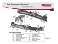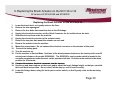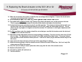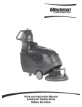
1
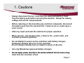
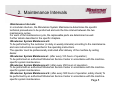
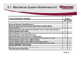
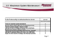
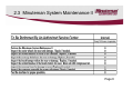
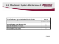
Service Manual
For the
SCV2832E, SCV2426,
SCV280000 & ES2832
Automatic Scrubbers
For:
o
Training
Troubleshooting
Adjustments
Contents
1
2
3
4
5
6
Cautions ---------------------------------------------------------------------Maintenance Intervals ---------------------------------------------------2.1 Customer Maintenance ---------------------------------------------2.2 Maintenance I after every 125 hours of operation-------------2 3 Maintenance II after every 250 hours of operation
2.3
operation------------2.4 Maintenance S after every 500 hours of operation,
minimum once per year------------------------------------------Service Mode ---------------------------------------------------------------3.1 Service Mode SC280000 -------------------------------------------Brush Pressure Settings--------------------------------------------------4.1 ES2832 and CP2832 ------------------------------------------------Error Codes -----------------------------------------------------------------5.1 Table of Error Codes (LCD)------------------------------------------
Page 4
Page 5
Page 6
Page 7
Page 8
Page 9
Page 10
Page 11
Page 13
Page 14
Page 16
Page 17
Page 2
Contents
5.4 Error Codes (LED) -------------------------------------------------------------- Page
6 Side Squeegee Adjustment (cylindrical) ----------------------------------------- Page
6.1 Side Squeegee Adjustment (disk)-------------------------------------------- Page
7 Rear Squeegee Adjustment
Page
8 Replacing the Brush Actuator On SC2832 Models--------------------------- Page
9 Trouble Shooting the Code 8 Error ----------------------------------------------- Page
10 Testing the Throttle Potentiometer----------------------------------------------- Page
11 Identifing the Cause of Trio Controllers ---------------------------------------- Page
12 Notes------------------------------------------------------------------------------------ Page
21
25
26
27
30
33
36
38
39
Page 3
1. Cautions
•
Always disconnect the A.C. Cord from the outlet and and D.C. Cord
from the battery pack before servicing the machine. Except for making
voltage
lt
and
d currentt measurements.
t
•
Before replacing or disconnecting any electrical componets, disconnect
the battery pack from the machine first. Failure to do so could cause a
short circuit.
circuit
•
After any repair work test the machine for proper operation.
•
When servicing the machine always observe the general safety and
accident prevention guidlines.
•
Do not attempt to power up the controllers with battery chargers.
Permanent damage will occur to the controller.
36 volt chargers usually have an output in excess of 48 volts.
•
Use only Minuteman approved battery chargers.
•
Do not apply power directly to the motors without first disconnecting
di conn cting
them from the controller circuit.
Page 4
2. Maintenance Intervals
•Maintenance Intervals:
In a modular structure, the Minuteman System Maintenance determines the specific
technical proceedures to be preformed and sets the time interval between the two
maintenance cycles.
For each of the maintenance cycle, the replaceable parts are determined as well.
Further details described in the specific chapters.
•Minuteman System Maintenance K:
To be performed by the customer (in daily or weekly intervals) according to the maintenance
and care instructions as specified in the operating instructions.
The operator must be professionally instructed after delivery of the machine by selling
dealer.
•Minuteman System Maintenance I: (after every 125 hours of operation)
To be preformed an authorized Minuteman Service Center in accordance with the machinespecific system maintenance.
•Minuteman System Maintenance II: (after every 250 hours of operation)
To be preformed an authorized Minuteman Service Center in accordance with the machinespecific system maintenance.
•Minuteman System Maintenance S: (after every 500 hours of operation, safety check) To
be performed by an authorized Minuteman Service Center in accordance with the machinespecific system maintenance.
Page 5
2.1 Minuteman System Maintenance K
Page 6
2.2 Minuteman System Maintenance I
Page 7
2.3 Minuteman System Maintenance II
Page 8
2.4 Minuteman System Maintenance S
Page
g 9
3. Service Mode
The Service mode switch can be used to lower the brush deck.
Press and hold the switch in the down position and the deck will lower. Once
it is in serv
service mode, the
e deck can
n raised
d and lowered
o
by pressing
r
tthe top or
lower part of the rocker switch. To return the machine back to normal
operation: Turn the key switch off and back on. The machine will reset.
The switch located below the seat
behind the panel on tthe SCVs.
Vs (Not
equipped on the SC280000 models)
The switch is located below the recovery
t k on th
tank
the ES2832 and
d CP2832 models.
d l
Page 10
3.1 Service Mode SC280000
Push and hold the brush
pressure down button for
15-20
15
20 seconds.
Once it is in service mode,
You can raise and lower
th deck
the
d kb
buy pressing
i th
the
brush pressure up and
down arrows.
To return the machine back
to normal operation: Turn
the key switch off and back
on. The machine will reset.
Page 11
3.2 Service Mode SCV2426
The Service Mode Switch on
the SCV2426 is located next
to the step on the front of the
machine on the operator’s
operator s
left side.
Once it is in service mode,
the deck can raised and
lowered by pressing the
upper or lower part of the
rocker switch.
To return the machine back to normal operation: Turn the key switch off
and back on. The machine will reset.
Page 12
4. Brush Pressure Settings
The brush pressure range can be
changed when changing the type of
deck on the SC2832E, SC2426P,
CP2832 and ES2832 models.
g
wire into
Connect the orange/violet
the terminal block with red/black wire
group for cylindrical decks and
unplug it for the disk decks.
The terminal block is located below
the Trio controller on the SCVs and
below the control panel on the ES
Trio Controller
Page 13
SCV 2832E Shown
4.1 ES2832,CP2832, and Phoenix 34
It is now available to change the brush pressure settings in
the field, when changing brush decks on current production
models of the Easy Scrub 28 and 32. No other modifications
will be required.
Changing the brush pressure settings will only be required,
when changing the cylindrical over to the disk deck or disk
over to the cylindrical decks. Changing the size only
(Example: Changing the 28 disk to 32 disk) will not require
changing the settings.
The orange/violet wire from the controller has been added to
change settings.
Connecting the orange/violet wire to the terminal block puts it
in the low-pressure mode for cylindrical decks.
Disconnecting the orange/violet from the terminal block puts
the brush pressure in the high-pressure
p
mode for disk decks.
Instructions:
1. Remove the switch panel, by removing the four screws.
2. Locate the terminal block. See Photograph.
Page 14
4.2 ES2832,CP2832, and Phoenix 34
Locate the Red/Black wire group
Locate the Orange/Violet wire
Page
g 15
5. Error Codes
The model SC280000 Rider scrubber uses a LCD display mounted above the steering wheel which
indicates the error code when they occur. The will be displayed as a four digit code with a picture of
a wrench next it. The top three are the hour meters for Total Time, Brush Motors and Drive Motor.
The SC2832E,
SC2832E SC2426P,
SC2426P ES2862
ES2 2 and CP2832
8 models uses
u
a 10
1 light LED
D display
d sp
to indicate
n
the
battery condition a error codes. The battery condition will be displayed with 1 to 10 LEDS. 10 LEDs
would be a fully charged battery one LED batteries are discharged.
When a error occurs 1 to 10 LEDS will flash indicating a specific error has occurred. There are two
aspects of the error codes.
A. How many LEDS are flashing
B. How many times it is flashing ( referred to as sequence)
Page 16
6. Table of Error Codes
Code Information or Fault Description
0810
0811
0812
0813
Comments and Corrective Action
1312
TILLER FAULT-1
For all Throttle Potentiometer Circuit Diagnostic Codes:
TILLER MAX WIPER DIFFERENCE ERROR
1- Check throttle wiring for sho
1
shorts
s or opens
opens. Repair or replace as necessary.
necessary
TILLER MAX PULL DOWN DIFFERENCE ERROR 2- If Diagnostic Code is not cleared, then replace throttle.
TILLER MAX PULL SAFE DIFFERENCE ERROR
"
"
"
"
Throttle displaced during start up. Check throttle springs (Riders) or drive switches (ES or
TILLER REFERENCE ERROR
CPs)
TILLER LO REFERENCE ERROR
1- Check throttle wiring for shorts or opens. Repair or replace as necessary.
TILLER HI REFERENCE ISO ERROR
2- If Diagnostic Code is not cleared, then replace throttle.
TILLER LO REFERENCE ISO ERROR
"
"
"
"
TILLER ERROR BOTH HAVE READINGS
"
"
"
"
EXCESSIVE CURRENT TRIP
Current draw of all output devices connected to TRIO+ exceeded 250 amp maximum limit.
Brush Actuator on Aux-1 exceeded 21 amp max. current limit. Check wiring or replace
SOFT AUX1 OVERCURRENT OCCURRED
device.
Squeegee Actuator on Aux-2 exceeded 21 amp max. current limit. Check wiring or replace
SOFT AUX2 OVERCURRENT OCCURRED
device.
1313
SOFT AUX3 OVERCURRENT OCCURRED
1314
1318
SOFT AUX4 OVERCURRENT OCCURRED
SOLUTION TANK EMPTY
Water Pump on Aux-3 exceeded 7 amp max. current limit. Check wiring or replace device.
Water Solenoid on Aux-4 exceeded 7 amp max. current limit. Check wiring or replace
device.
Solution Tank Empty signal from float switch
131C
1321
1322
1411
1412
1413
1414
1500
1501
1507
1600
1D02
1E03
1E04
1E06
SOFT ALARM OVERCURRENT OCCURRED
AUX1 OVERCURRENT 2 OCCURRED
AUX2 OVERCURRENT 2 OCCURRED
ERROR AUX 1 POSITIVE SHORTED LOW
ERROR AUX 1 NEGATIVE SHORTED LOW
ERROR AUX 2 POSITIVE SHORTED LOW
ERROR AUX 2 NEGATIVE SHORTED LOW
BRAKE FAULT OPEN CIRCUIT
BRAKE FAULT 2
BRAKE OVER CURRENT ERROR
HIGH BATTERY ERROR
FRONT END SPEC CHANGE TRIP
INHIBIT ACTIVATED
INHIBIT ACTIVATED2
INHIBIT INPUT OUT OF RANGE
Alarm circuit exceeded 2 amp max. current limit. Check wiring or replace device.
Device connected to Aux-1 exceeded 12 amps for > .1 sec Check Brush Actuator.
Device connected to Aux 2 exceeded 12 amps for > .1 sec. Check wiring or replace device.
Check Brush Actuator Motor and wiring. Repair or replace as necessary.
Check Brush Actuator Motor and wiring. Repair or replace as necessary.
Check Squeegee actuator and wiring. Repair or replace as necessary.
Check Squeegee actuator and wiring. Repair or replace as necessary.
Check Electric Brake circuit for a faulty connection.
Check Electric Brake circuit for a faulty connection.
Check Brake circuit wiring and brake
brake. Repair or replace as necessary
necessary.
Battery is overcharged or damaged. Replace battery.
Drive parameters have been reprogrammed. Cycle power with key switch.
Solution Tank Empty - Check float switch
Recovery Tank Full - Check float switch
Invalid Inhibit signal. Check wiring and device. Repair or replace as necessary.
0814
0815
0816
0817
0818
1310
1311
Page 17
6. Table of Error Codes
2C00
2C01
2C02
2C03
2F01
3A00
7000
7001
LOW BATTERY ERROR
LOW BATTERY ERROR2
SOFT BATTERY LOCKOUT OCCURRED
SOFT BATTERY LOCKOUT 2 OCCURRED
TILLER DISPLACED ERROR
BAD SETTINGS
STARTUP WITH PUSH SELECTED
PUSH ACTIVATED IN DRIVE MODE
Battery Charge to low. Recharge battery.
Battery Charge to low. Recharge battery.
Battery Charge to low. Recharge battery.
Battery Charge to low. Recharge battery.
Throttle displaced on Power-up. Release throttle and then re-engage throttle.
Illegal program parameter settings.
Freewheel Input signal detected at startup. Disconnect Freewheel input.
Freewheel Input signal activated while driving. Disconnect Freewheel input.
7500
7600
7601
7602
7603
7604
TILLER COMMS TIMEOUT
TIMEO T
SOFT BRUSH MOTOR DISCONNECTED ERROR
SOFT BRUSH CURRENT FOLDBACK
SOFT BRUSH CURRENT FOLDBACK2
SOFT BRUSH CURRENT FOLDBACK3
SOFT BRUSH INHIBIT
Problem with
h LCD Module or wiring.
n Repair or replace as necessary.
necessary
Check Brush Motor wiring and connectors
Too much Brush Pressure/Current. Check for jammed Brushes or Deck or Brush motor short.
Too much Brush Pressure/Current. Check for jammed Brushes or Deck or Brush motor short.
Too much Brush Pressure/Current. Check for jammed Brushes or Deck or Brush motor short.
Brush Inhibit signal is active.
7605
7700
7701
7702
7703
BRUSH STARTUP OVERCURRENT DETECTION
SOFT VACUUM MOTOR DISCONNECTED ERROR
SOFT VACUUM CURRENT FOLDBACK
SOFT VACUUM CURRENT FOLDBACK2
SOFT VACUUM CURRENT FOLDBACK3
Possible Brush motor problem or shorted brush circuit wiring.
Check Vacuum Motor wiring and connectors
Too much Vac motor current. Check for shorted Vac motor or wiring.
Too much Vac motor current. Check for shorted Vac motor or wiring.
Too much Vac motor current. Check for shorted Vac motor or wiring.
7800
7801
7802
7803
7804
7880
7900
7901
8000
9000
TRACTION MOTOR FAULT-1
TRACTION MOTOR OVER CURRENT ERROR
TRACTION MOTOR IN FOLDBACK STATE
MOTOR LINE VOLTAGES INSTABILITY TIMEOUT
TRACTION MOTOR IN DRIVE BOOST
TRACTIO SPEED INPUT OUT OF RANGE
TRACTION
EMERGENCY STOP ERROR
SOFT BELLY BUTTON ACTIVATED
SERVICE MODE
BRUSHES NOT FITTED
Check Traction Motor wiring and connectors
Too much Traction motor current. Check for shorted Traction motor or wiring.
Traction Motor was overloaded for too long, Control limiting current to protect motor.
Possible Traction Motor or loose wiring problem.
Traction Motor under heavy load or Current Limit / Fold back parameters set too low.
Check Throttle Potentiometer and wiring.
Emergency Stop function activated.
Safety Bar switch is activated. (ES and CP models only)
Service Timer limits have been reached.
Check Brush Deck to make sure Brushes are fitted properly.
Page 18
6. Table of Error Codes
0003
0100
0204
0705
0706
0A01
0B02
0B0B
1704
1705
1706
1800
1802
1B20
1B21
2102
2103
2D01
3100 Shorted Circuit
3101
3102
3103
3104
3105
3200
3201
3210
3211
For All of these Diagnostic Codes:
1- Turn Off Key switch and disconnect batteri
1
batteries.
s.
2- Wait 1 minute.
3- Reconnect Batteries and turn on key switch.
4- If Diagnostic Code is not cleared, then replace TRIO+ / TRIO+HD control.
IMPORTANT!
TRIO+ / TRIO+HD can be damaged internally by shorting Batt+ to any of it's Inputs or Outputs.
Check Wiring Harness for shorts before installing a replacement Control.
If replacement control fails, then replace Wiring Harness before installing any more Controls.
Check For Shorts on the Brush and Drive Motor Circuits. Also Water inside of motors.
Page 19
6. Table of Error Codes
3212
For All of these Diagnostic Codes:
3213
1- Turn Off Key switch and disconnect batteries.
3214
2- Wait 1 minute.
3- Reconnect Batteries and turn On Key switch.
3601
4- If Diagnostic Code is not cleared, then replace TRIO+
4
TRIO / TRIO+HD
HD control.
3602
3603
3608
3609
IMPORTANT!
360A
TRIO+ / TRIO+HD can be damaged internally by shorting Batt+ to any of it's Inputs or Outputs.
360B
Check Wiring Harness for shorts before installing a replacement Control.
360C
If replacement control fails, then replace Wiring Harness before installing any more Controls.
360D
360E
7501
Page 20
5.1 Table Error Codes (LED)
Single flash Low Batteries- Charge
the batteries
Single flash Traction drive motor disconnected
Single flash - Brush motor disconnected
Single flash - Brush actuator overload
Two flash – Squeegee actuator overload
Page 21
5.1 Table Error Codes (LED)
Single flash – Vacuum motor disconnected
Single flash
flash- Off Isle Wand Activated
Si l flflashSingle
h Potentiometer fault
Single flash
flash- Control fault check all connections to
controller- see “Trouble Shooting the Code 8 Error”
Page 22
5.1 Table Error Codes (LED)
Single
g Flash- Solution tank empty- Riders onlyy
Two flash-Not
Not used
Th
Three
flflash-Water
h
solenoid fault
Four flash-Water pump fault
Five flash-Electric
flash Electric brake circuit fault
fault- Check all connection to
the brake.
Page 23
5.1 Table Error Codes (LED)
Single flash- High battery voltage- Check all connections
Ripple-Throttle activated during start up.
Page 24
6. Side Squeegee Adjustment
SCV2426 & SCV2832E Only
The side squeegees on the
cylindrical decks can be
adjusted by loosening the two
black knobs and moving the
squeegee assemble up or
down.
Cylindrical Decks
B
E
The brush assembly may be
accessed by removing the
yellow knob C. The squeegee
assembly is hinged at D
D.
Remove the three wing nuts
that mount the brush idler
bearing assembly E and
remove the brush roll.
Repeat the process on both
sides of the machines
A-Side Squeegee
B-Black Adjustment Knob
C-Yellow
C
Yellow Brush Access Knob
D-Side Squeegee Hinge
E-Bush Access Plate
Page 25
6.1 Side Squeegee Adjustment
SCV2426 & SCV2832E Only
Disk Decks
Wing Nuts
The side squeegee
assemblies can be
adjusted by loosening
the two wing nuts and
moving the assembly
up or down.
Wing Nuts
Repeat the process on
both sides, if needed.
Squeegee
Assembly
Page 26
7. Squeegee Adjustment
Later Models Onlyy
•
The pitch of the squeegee
can be adjusted by turning
th knob.
the
k b L
Loosen th
the wing
i
nuts before adjusting.
Tighten the wing nuts to
lock into position
position.
Wing Nuts
Adjustment Knob
Page 27
7. Rear Squeegee Adjustment
Later Models Only
Page 28
7. Rear Squeegee Adjustment
Later Models Onlyy
Page 29
8. Replacing the Brush Actuator on the SCV 28 or 32
All Versions Of SCV2832E and SC280000
Replacing the Brush Actuator on the SCV 28 or 32
1.
2.
3.
4.
5.
6.
7.
8.
9.
10.
11.
12.
Lower the brush deck, so it gently rests on the floor.
Remove the side squeegees.
Remove the four bolts that mount the deck to the lift linkage.
Unplug the electrical connector and the Quick Connector for the solution from the deck.
Slide the deck out from under the machine.
Unplug the electrical connector to the actuator motor.
Remove the two pins that mount the actuator on each end.
Remove the actuator from the machine.
Mount the new actuator. Do not connect the electrical connector on the actuator at this point.
Connect the battery pack.
Turn the machine on.
Put the machine in Service Mode. Hold one of the brush pressure buttons on the touch pad for over 20
seconds and release on the model SC2800000. The SC28/32E’s service mode switch is located in the
controller compartment under the seat, on the operators left side. Push the rocker switch in the down
position for 20 seconds.
13 Connect the actuator electrical connector into the harness
13.
harness.
14. Use the up and down buttons on the touch pad to adjust the brush linkage height, so that you can slide
the brush deck into position. Do not raise it all the way up, until it is set correctly.
15. Lower the linkage down, using the touch pad or rocker switch, so that it gently rests on the mounting
brackets.
Page 30
8. Replacing the Brush Actuator on the SCV 28 or 32
All Versions Of SCV2832E and SC280000
16. Slide the brush deck into position, install the four mounting bolts and tighten. Connect the brush motor
connector and solution quick connector.
17 Locate
17.
L
t the
th bl
black
k rubber
bb removable
bl plug
l
on the
th right
i ht side
id off th
the actuator
t t and
d remove.
18. For models with cylindrical decks only. Remove the plastic side deck cover on the operators left side.
This is a gray plastic piece screwed to the side of the solution tank above the deck area.
19. Use the brush pressure up button to raise it up a little at a time. The clearance between the top belt cover
and the under side of the tank should between 1/4 to 3/8 inch, when the deck stops rising up. Do not
allow
ll
it tto rise
i any hi
higher
h or it might
i ht over load
l d the
th actuator.
t t
If it continues
ti
to
t rise
i higher,
hi h
adjustment
j t
t will
ill
be required.
20. For Disk machines only, the actuator should be set so that you can slide the brushes under the deck and
not bottom out under the machine.
21. Adjust the actuator adjustment screw to change setting see drawing. Turn the screw no more than 1/8 of a
t
turn
att a time.
ti
Th
The adjustment
dj t
t screw closest
l
t to
t the
th shaft
h ft controls
t l how
h
high
hi h it rises.
i
The
Th screw furthest
f th t
from movable controls maximum down pressure. Look at the rubber plug to determine which way to turn
the screw.
22. Lower the brush deck and return it back up for the new settings to change.
23. Adjust the down setting so that the actuator cannot lift the drive motor off the floor. Set it so it only lifts
some pressure off
ff the drive wheel.
24. Once the correct setting is made replace the rubber plug into the side of the actuator motor.
25. Replace side plastic cover.
26. Turn the key switch off and back on.
27. Test the machine.
Page 31
8.1 Actuator Adjustment
Page 32
8.2 Entering Service Mode with a Stuck Actuator
Page 33
9. Trouble Shooting the Code 8 Error
ES2832, CP2832, SCV2426 and SC2832E Models Only)
1. Check for loose or burnt connections on the controller, batteries, cables and
the circuit breaker. Make the sure the circuit breaker is not damaged.
2. Measure the total battery voltage at the batteries and at the battery
connections on the controller. They should be exactly the same. A 1/10 of a
volt or more difference would indicate a problem in the connections.
3. Check to see, if the operator has recently washed the machine down and got
water inside off the brush motor or in the controller area.
4. On the ES2832 and CP2832 only disconnect the plug on the Service Mode
Switch. This is accessible by tilting the solution tank forward. Power the
machine up with it disconnected
disconnected. If error code is cleared repla
replace the switch.
5. Check for a disconnected or an open circuit or faulty potentiometer on the
throttle or speed circuit. Controller may not be detecting it in the circuit. Do a
continuity test. See “Testing the potentiometer” section.
Page 34
9. Trouble Shooting the Code 8 Error
6. Disconnect one motor connector from the Trio controller at a time and
disconnect the batteries for 1 minute and restart the machine. If the code
8 disappears and is replaced by a different code, the circuit disconnected
should be considered suspect. For example the brush was disconnected.
The code 8 is replaced by code 3. Code 3 indicates the brush motor is
disconnected Check for a loose or broken connection at the brush deck
disconnected.
deck.
Check to see if water has gotten inside the brush motor. Check for a
shorted motor.
7. Static electricity. Check both the ground chains; there is one on the brush
deck and one on the rear of the machine. They should be contacting the
floor. The one on the deck should touch the floor when the deck is down.
They also should have continuity between the end of the chain and the
frame
a eo
of tthe
e machine.
ac e Repair
epa o
or cclean
ea if needed
eeded if needed.
eeded
8. If everything checks OK, replace the Trio Controller.
Note controllers can be damaged by loose connections on inputs and outputs, static
electricity and water on electrical components such as on or in the controller and motors.
Page 35
10. Testing the Throttle Potentiometer
1.
2.
3.
4.
5.
6
6.
7.
The throttle potentiometer resistance can be measured with an ohmmeter.
Unplug
g the throttle potentiometer at the connector next to it.
Analog type meters are recommended for this test.
Measure the resistance across the red and white wire on the potentiometer assembly. It should
measure approximately 5K (5 thousand ohms).
potentiometer, the resistance should be zero
Measure across the black and white wires on the p
ohms with pedal on the riders in the neutral position or speed knob on the ES2832 and CP2832 in
the full counterclockwise position. When the pedal or knob is moved to the full throttle position, in
should be a smooth resistance change without dropping out. It should measure approximately 5K
(5 thousand ohms) in the full position.
Measuring across the black and
d the
th red
d wire
i th
the resistance
i t
should
h ld b
be approximately
i t l 5K (5
thousand), when in the neutral position. When the pedal is at full throttle or the knob is full speed
position, the resistance should drop to zero.
If adjustment is needed, loosen the nut and screw on the throttle arm. Adjust the potentiometer
shaft with a flat tip screw driver, until it is se
set according to the information above (on the riders
only).
Potentiometer Assembly
Adjust Here
Page 36
10. Testing the Throttle Potentiometer
8. If they do not find a problem here, have them retest at the connector at the Trio
controller.
9. Reconnect the plug at the throttle potentiometer.
10. Unplug the P3 connector (The large white connector) on the controller under the seat on the riders
and behind the two rear panels on the ES2832s and CP2832s.
11 L
11.
Locate
t th
the bl
black/orange
k/
and
d th
the bl
black/pink
k/ i k wire.
i
12. Measuring across the black/orange and black/pink wires the resistance should be zero ohms in the
neutral position. It should 5k in the full throttle position.
13. Measure across the black/pink and the black/white wires. The resistance should be 5K (5
thou
thousand)
in the neutral
t position.
ition When the
th pedal is at full throttle the resistance
re istance should drop to
zero.
14. If your reading is different with this test check all the connections between the controller and the
throttle control, including the seat switch.
Note: when moving the throttle to the full position
position, the resistance should
ould be smooth
smooth, without
dropping out for both tests. If the resistance does not go to 5K during the test, the arm and
the potentiometer may need to be adjusted to achieve it.
Page 37
11. Identifying the Cause of Trio Failures
1.
2.
3.
Check for loose or burnt connections on the controller, batteries, cables and the circuit breaker.
Make the sure the circuit breaker is not damaged (burnt or cracked).
Test the chassis drive motor harness for broken wires (riders only). Disconnect the plug labeled
Traction on the Trio controller. Connect a digital multi-meter to the plug on the two large wires.
Set the meter for Ohms (resistance). The resistance should be .3 to .4 ohms. Turn the steering
wheel in both directions until it stops several times.
imes Monitor the meter w
while
ile turnin
turning. The
he
resistance should not change or vary while turning. Any variation even .1 ohm would be indicate
a broken wire, which could cause spikes and surges, that could damage the Trio controller.
Measure the total battery voltage at the batteries and at the battery connections on the controller.
They should be exactly the same. A 1/10 of a volt or more difference would indicate a problem in
the connections.
Page 38
12. Notes
Page 39