1
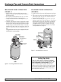
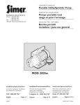
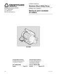
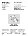
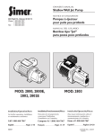
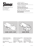
OWNER’S MANUAL
Portable Utility/Sprinkler Pump
®
293 Wright St., Delavan, WI 53115
Phone: 1-800-468-7867
1-800-546-7867
Fax:
1-800-390-5351
Model 2825ss
Installation/Operation/Parts
For further operating, installation, or maintenance assistance:
Call 1-800-468-7867
©2003 PRINTED IN U.S.A.
SIM590 (Rev. 5/21/03)
Safety
2
READ AND FOLLOW
SAFETY INSTRUCTIONS!
This is the safety alert symbol. When you see this
symbol on your pump or in this manual, look for
one of the following signal words and be alert to the
potential for personal injury.
warns about hazards that will cause serious
personal injury, death or major property damage if
ignored.
warns about hazards that can cause serious
personal injury, death or major property damage if
ignored.
warns about hazards that will or can cause
minor personal injury or property damage if ignored.
The label NOTICE indicates special instructions which
are important but not related to hazards.
Carefully read and follow all safety instructions in this
manual and on pump.
Keep safety labels in good condition.
Replace missing or damaged safety labels.
GENERAL SAFETY
1. To avoid risk of serious bodily injury and property
damage, read the safety instructions carefully before
installing this pump.
2. Follow local and/or national plumbing and electrical
codes when installing the pump.
3.
Hazardous Pressure. The pump body
may explode if used as a booster pump unles a relief
valve capable of passing the full pump flow at 60 PSI
(414 kPa) is installed. Never run the pump dry. To do
so can damage internal parts, overheat pump (which
can cause burns to people handling or servicing
pump), and will void warranty!
WARNING
Hazardous pressure!
Install pressure relief
valve in discharge pipe.
Release all pressure on
system before working on
any component.
4.
Risk of fire or explosion. To avoid risk
of fire and explosion, Pump Water Only with this
pump. Do not use this pump in an atmosphere that
might contain flammable fumes or vapors.
5.
Burn Hazard. If water is trapped in the
pump during operation it may turn to steam.
Trapped steam can lead to explosion and burns.
Never run the pump with the outlet closed or
obstructed.
7. If used with a well for potable water, always disinfect
the well and test the water for purity before using.
Check with your local health department for testing
procedures.
8. Complete pump and piping must be protected against
freezing. Freezing will cause damage and void the
warranty.
9. This pump is not designed, nor intended, for the
pumping of chemicals or corrosive liquids. Pump
water only with this pump.
10. Do not run pump dry. If the pump is dry, damage will
result and void the warranty.
ELECTRICAL SAFETY
The pump is supplied with a 3-conductor grounding type cord. Connect only to a properly grounded, GFCI protected outlet. Do not lift the pump by the
electrical cord.
Match the motor voltage and the power supply
voltage. The supply voltage must be within +/- 10%
of the motor nameplate voltage. Incorrect voltage can
cause fire or seriously damage the motor and will void
the warranty. If in doubt, consult a licensed electrician.
The pump is non-submersible. Keep the motor dry
at all times. Do not wash the motor. Do not
immerse. Protect the motor from wet weather.
If using an extension cord, use only a UL approved
indoor/outdoor, 3-wire, grounding type cord. Do
not allow any part of the cord or the receptacle ends to
sit in water or in damp locations.
Unplug the pump before servicing. To avoid fatal
shocks, proceed as follows if the pump needs
servicing.
A. Disconnect the power
to the pump outlet box
before pulling the
pump plug. Modern
motors are designed
to operate at high
temperatures. To avoid
burns when servicing
pump, allow it to cool
Hazardous voltage. Can
for 20 minutes after
shock, burn, or cause death.
shut-down before
Ground pump before connecting
handling.
to power supply. Disconnect
B.
Take extreme care
power before working on pump,
when changing fuses.
motor or tank.
To reduce the chance of
fatal electrical shocks, DO NOT stand in water or put
your finger in the fuse socket.
C. Ground the pressure switch or motor before before
running this pump.
D. Plug pump into a Ground Fault Circuit Interrupter
(GFCI) protected grounded outlet only.
WARNING
For parts or assistance, call Simer Customer Service at 1-800-468-7867
/ 1-800-546-7867
Table of Contents
3
Page
General Safety .....................................................................................................2
Warranty ..............................................................................................................3
Installation (Well Pumps) .................................................................................4, 5
Connecting Discharge Piping...............................................................................6
Pressure Booster and Sprinkling ...........................................................................7
Preparing To Start The Pump............................................................................8, 9
Troubleshooting ...................................................................................................9
Repair Parts .......................................................................................................10
Simer Limited Warranty
SIMER warrants to the original consumer purchaser (“Purchaser”) of its products
that they are free from defects in material or workmanship.
If within twelve (12) months from the date of the original consumer purchase
any such product shall prove to be defective, it shall be repaired or replaced at
SIMER’s option, subject to the terms and conditions set forth below. Your original receipt of purchase is required to determine warranty eligibility.
Exceptions to the Twelve (12) Month Warranty
Five (5) Year Warranty:
If within five (5) years from original consumer purchase any Pre-Charge water
system tank shall prove to be defective, it shall be repaired or replaced at
SIMER’s option, subject to the terms and conditions set forth below.
General Terms and Conditions
Purchaser must pay all labor and shipping charges necessary to replace product
covered by this warranty. This warranty shall not apply to acts of God, nor shall
it apply to products which, in the sole judgement of SIMER, have been subject
to negligence, abuse, accident, misapplication, tampering, alteration; nor due
to improper installation, operation, maintenance or storage; nor to other than
normal application, use or service, including but not limited to, operational failures caused by corrosion, rust or other foreign materials in the system, or operation at pressures in excess of recommended maximums.
Requests for service under this warranty shall be made by returning the defective product to the Retail outlet or to SIMER as soon as possible after the discovery of any alleged defect. SIMER will subsequently take corrective action as
promptly as reasonably possible. No requests for service under this warranty
will be accepted if received more than 30 days after the term of the warranty.
This warranty sets forth SIMER’s sole obligation and purchaser’s exclusive remedy for defective products.
SIMER SHALL NOT BE LIABLE FOR ANY CONSEQUENTIAL, INCIDENTAL, OR
CONTINGENT DAMAGES WHATSOEVER.
THE FOREGOING WARRANTIES ARE EXCLUSIVE AND IN LIEU OF ALL
OTHER EXPRESS WARRANTIES. IMPLIED WARRANTIES, INCLUDING BUT
NOT LIMITED TO THE IMPLIED WARRANTIES OF MERCHANTABILITY AND
FITNESS FOR A PARTICULAR PURPOSE, SHALL NOT EXTEND BEYOND THE
DURATION OF THE APPLICABLE EXPRESS WARRANTIES PROVIDED HEREIN.
Some states do not allow the exclusion or limitation of incidental or consequential damages or limitations on how long an implied warranty lasts, so the
above limitations or exclusions may not apply to you. This warranty gives you
specific legal rights and you may also have other rights which vary from state
to state.
SIMER • 293 Wright St. • Delavan, WI U.S.A. 53115
Phone: 1-800-468-7867 / 1-800-546-7867 • Fax: 1-800-390-5351
For parts or assistance, call Simer Customer Service at 1-800-468-7867
/ 1-800-546-7867
Installation
4
SPECIFICATIONS
Power Supply Required. ...................................115 Volts
Motor Duty ...................................................Continuous
Circuit Requirement (minimum) .....................15.0 Amps
Discharge Adapter .......................................................1”
SHALLOW WELL JET PUMP
INSTALLATIONS:
• Have a vertical depth of 25’ or less.
• Have one pipe from the well to the pump case.
• Can be installed in a bored or drilled well, or in a
driven well.
REPLACING AN OLD PUMP
Hazardous voltage. Can shock, burn or
kill. Disconnect power to pump before working on
pump or motor.
1. Drain and remove the old pump. Check the old pipe
for scale, lime, rust, etc., and replace it if necessary.
To Household
Water System
Pump Priming
Tee and Plug
Suction Pipe
From Well
Priming
Tee and
Plug
Check
Valve
Drive
Coupling
2. Install the pump in the system. Make sure that all
pipe joints in the suction pipe are air-tight as well as
water tight. If the suction pipe can suck air, the
pump will not be able to pull water from the well.
3. Adjust the pump mounting height so that the plumbing connections do not put a strain on the pump
body. Support the pipe so that the pump body does
not take the weight of piping or fittings.
You have just completed the well plumbing for your
new shallow well jet pump. Please go to Page 6 for
discharge pipe and tank connections.
WELL POINT (DRIVEN POINT)
INSTALLATION (FIGURE 1)
1. Drive the well, using “drive couplings” and a “drive
cap”. “Drive fittings” are threaded all the way
through and allow the pipe ends to butt against each
other so that the driving force of the maul is carried
by the pipe and not by the threads. The ordinary fittings found in hardware stores are not threaded all
the way through the fitting and can collapse under
impact. “Drive fittings” are also smoother than standard plumbing fittings, making ground penetration
easier.
2. Mount the pump as close to the well as possible
3. Use the fewest possible fittings (especially elbows)
when connecting the pipe from the well point to the
pump suction port. The suction pipe should be at
least as large as the suction port on the pump
(include a check valve if your pump is not equipped
with one – see Figure 1). Support the pipe so that
there are no dips or sags in the pipe, so it doesn’t
strain the pump body, and so that it slopes slightly
upward from the well to the pump (high spots can
cause air pockets which can air lock the pump). Seal
the suction pipe joints with teflon tape. Joints must
be air and water tight. If the suction pipe can suck
air, the pump cannot pull water from the well. If
one well point does not supply enough water, consider connecting two or three well points to one suction pipe.
You have just completed the suction piping for your
new shallow well jet pump. Please go to Page 6 for
discharge pipe and tank connections.
Drive
Point
Not
to
Scale
3938 0401
Figure 1 – Driven Point Installation
PERFORMANCE
Model
2825ss
0
10
10
8.5
20
8.0
Output Pressure
30
7.5
40
7.0
For parts or assistance, call Simer Customer Service at 1-800-468-7867
50
6.0
/ 1-800-546-7867
Maximum
PSI
80
Installation
5
CASED WELL INSTALLATION, 2” OR
LARGER CASING (FIGURE 2)
INSTALLATION FOR
SURFACE WATER (FIGURE 3)
1. Mount the pump as close to the well as possible.
2. Assemble the foot valve, strainer, and well pipe (see
Figure 2). Make sure that the foot valve works freely.
3. Lower the pipe into the well until the strainer is five
feet above the bottom of the well. It should also be at
least 10 feet below the well’s water level while the
pump is running in order to prevent the pump from
sucking air. Install a sanitary well seal.
4. Install a priming tee, priming plug, and suction pipe
to the pump (see Figure 2). Connect the pipe from the
well to the pump suction port, using the fewest possible fittings – especially elbows – as fittings increase
friction in the pipe (however, include a foot valve –
see Figure 2). The suction pipe should be at least as
large as the suction port on the pump. Use teflon tape
or a teflon-based pipe joint compound on threaded
pipe joints. Support the pipe so that there are no dips
or sags in the pipe, so it doesn’t strain the pump
body, and so that it slopes slightly upward from the
well to the pump (high spots can cause air pockets
which can air lock the pump). Seal the suction pipe
joints with teflon tape. Joints must be air and water
tight. If the suction pipe can suck air, the pump cannot pull water from the well.
You have just completed the suction piping for your
new shallow well jet pump. Please go to Page 6 for
discharge pipe and tank connections.
1. The pump should be installed as close to the water as
possible, with the fewest possible fittings (especially
elbows) in the suction pipe. The suction pipe should
be at least as large as the suction port on the pump.
2. Assemble a foot valve and suction pipe (see Figure 3).
Make sure that the foot valve works freely. Use teflon
tape or a teflon-based pipe joint compound on
threaded pipe joints. Protect the foot valve assembly
from fish, trash, etc, by installing a screen around it
(see Figure 3).
3. Lower the pipe into the water until the strainer is five
feet above the bottom. It should also be at least 10
feet below the water level in order to prevent the
pump from sucking air.
4. Install a priming tee, priming plug, and suction pipe
to the pump (see Figure 3). Support the pipe so that
there are no dips or sags in the pipe, so it doesn’t
strain the pump body, and so that it slopes slightly
upward from the well to the pump (high spots can
cause air pockets which can air lock the pump). Seal
the suction pipe joints with teflon tape. Joints must be
air and water tight. If the suction pipe can suck air,
the pump cannot pull water from the well.
You have just completed the plumbing for your new
shallow well jet pump. Please go to Page 6 for discharge pipe and tank connections.
To Household
Water System
To Household
Water System
Pump Priming
Tee and Plug
Pump Priming
Tee and Plug
Check
Valve
Suction Pipe
From Well
Check
Valve
Suction Pipe
From Well
Priming
Tee and
Plug
Priming
Tee and
Plug
Sanitary
Well Seal
Well
Casing
Foot
Valve
10'
Min.
Foot
Valve
5–10'
Not
to
Scale
Screen
3941 0401
Figure 2 – Cased Well Installation
Figure 3 - Surface Water Installation
For parts or assistance, call Simer Customer Service at 1-800-468-7867
/ 1-800-546-7867
10'
Min.
5'
Discharge Pipe and Pressure Tank Connections
6
PRE-CHARGE TANK CONNECTION
(FIGURE 4)
STANDARD TANK CONNECTION
(FIGURE 5)
1. Install two tees in the pump discharge port (see
Figure 4). The pipe size must be at least as large as
the discharge port.
2. Run a pipe or reinforced hose from one arm of the
first tee to the port on the pre-charged tank.
3. Connect the other end of the discharge tee to your
plumbing system.
4. Check the pre-charge of air in the tank with an ordinary tire gauge. The pre-charge should be 2 PSI less
than the cut-in setting of the pump’s pressure switch.
The pre-charge is measured when there is no water
pressure in the tank. Your new pump has a 30/50 PSI
switch, so adjust the tank pre-charge pressure to 28
PSI.
Congratulations! You have just completed the tank
connection for your jet pump.
1. Install one tee in the pump discharge port (see Figure
5).
2. Run a pipe from the pump discharge port to the inlet
port of your tank. The pipe size must be at least as
large as the discharge port.
3. Remove the 1/8” NPT pipe plug from the pump Air
Volume Control (AVC) port (see Figure 5). Run tubing
from the pump’s AVC port (see Figure 5) to the port
on the AVC mounted on the tank. See instructions
provided with tank and AVC for details. AVC port
location will vary, depending on your pump model
(see exploded views, Page 10).
To Household
Water System
To Household
Water System
Pump Priming
Tee and Plug
Pressure Switch
Check
Valve
Pump
Priming Tee
and Plug
Pressure
Switch
Air Volume
Control
Air Volume
Control Tube
Suction Pipe
From Well
Pump AVC Port
From
Well
Not
to
Scale
Figure 5 – Standard Tank Connections
Sealing Pipe Joints
Not
to
Scale
Figure 4 – Pre-charged Tank Connections
Use only Teflon tape for making all threaded
connections to the pump itself. Do not use pipe
joint compounds on plastic pumps: they can
react with the plastic in pump components.
Make sure that all pipe joints in the suction pipe
are air tight as well as water tight. If the suction
pipe can suck air, the pump will not be able to
pull water from the well.
For parts or assistance, call Simer Customer Service at 1-800-468-7867
/ 1-800-546-7867
Pressure Boosting and Sprinkling
7
BOOSTING CITY WATER PRESSURE
Hazardous pressure. Never run the pump
against a closed discharge. To do so can boil the water
inside the pump, causing hazardous pressure in the
pump causing the risk of explosion and possibly scalding
persons nearby. See Figure 6.
Connect the Pump Inlet
to the Water Faucet
for use with Sprinklers.
Water Faucet
Hose
Adapters
3942 0401
Figure 8 – Connect pump to a spigot for use with sprinklers. Connect with adapters supplied with pump
1117 0993
Figure 6: Do Not Run Pump With Outlet Shut Off
When using the pump as a high-pressure washer, use
only a reinforced high pressure hose or pipe for the discharge line.
When using a garden hose, install adapters to the pump
suction and the discharge. The suction hose will require
two female ends. Either use a standard washing machine
supply hose or modify a short piece of standard 1” garden hose as a suction line (See Figure 7).
PIPING
Both the suction and discharge ports are tapped for 1"
BSP threads. If using hoses, use hose adapters. See
Figure 7. Do not use a hose on the suction if pumping
from lakes, streams or ponds. The hose will collapse and
cause pump failure. Install a strainer with a foot valve on
the end of the suction line. Inspect and clean the strainer
frequently (Figure 9).
NOTICE: An air leak in the suction pipe may draw air in
although no water leaks out. Make sure there are no air
leaks or air pockets in the suction pipe.
115V, GFCI
Protected,
Grounded
Outlet Box
Discharge Line
(Garden Hose or
Rigid Pipe)
Hose
Adapters
Hose Adapters
Suction Line
(Garden Hose or
Rigid Pipe)
Figure - 7 Hose adapter installation
Footvalve with
strainer (clean
frequently)
Hazardous pressure. Do not shut off the
hose or the sprinklers while the pump is running. The
hose or sprinkler head may explode.
Figure - 9 Strainer and footvalve installaton
For parts or assistance, call Simer Customer Service at 1-800-468-7867
/ 1-800-546-7867
Preparing To Start The Pump
PRIMING/OPERATION
NOTICE: Do not run the pump dry. Running the pump
without water can damage the impeller and may damage
the seal, causing leaking or flooding, and will void
warranty.
All suction connections must be airtight. Make sure the
suction lift is not more than 25 feet (7.6M). Fill the pump
body through the priming port before starting the pump.
Start the pump; it should pump water in under 10 minutes (depending on the length of the suction hose and
the height of the pump above water).
PREPARING TO START THE PUMP
(REFER TO FIGURE 10)
Risk of burns. Never run pump dry.
Running the pump without water may cause the pump to
overheat, damaging the seal and possibly causing burns
to persons handling the pump. Fill the pump with water
before starting.
Hazardous Pressure. Never run the pump
against closed discharge. To do so can boil water inside
pump, causing hazardous pressure in unit, risk of explosion and possibly scalding persons handling pump.
1. Remove the priming plug from the priming tee and
fill the pump. Fill all piping between the pump and
the well and make sure that all piping in the well is
full. If you have also installed a priming tee in the
suction piping, remove the plug from the tee and fill
the suction piping. See Figure 10.
2. Replace all fill plugs.
3. Power on! Start the pump. If you don’t have water
after 2 or 3 minutes, stop the pump and remove the
fill plugs. Refill the pump and piping. You may have
8
to repeat this several times in order to get all of the
trapped air out of the piping. A pump lifting water 25’
may take as long as 15 minutes to prime.
4. After the pump has built up pressure in the system
and shut off, check the pressure switch operation by
opening a faucet or two and running enough water
out to bleed off pressure until the pump starts. The
pump should start when the pressure drops to 30 PSI
and stop when the pressure reaches 50 PSI. Run the
pump through one or two complete cycles to verify
correct operation. This will also help clean the system
of dirt and scale dislodged during installation.
Congratulations on a successful installation.
If you were unsuccessful, please refer to the
Troubleshooting section (Page 9) or call our customer
service technical staff at 1-800-468-7867.
Remove the
plug and
fill the pump
and the piping
through the
priming tee.
Figure 10: Prime the Pump
For parts or assistance, call Simer Customer Service at 1-800-468-7867
/ 1-800-546-7867
Troubleshooting
SYMPTOM
9
POSSIBLE CAUSE(S)
CORRECTIVE ACTION
Motor will not run
Fuse is blown or circuit breaker tripped
DISCONNECT POWER;Replace fuse or reset circuit breaker.
Motor runs hot and
the overload kicks
off or the does not
run and only hums.
Voltage is too low
Check voltage being supplied to the pump.
Motor runs but no
water is delivered*
Pump during new installation did
not pick up prime through:
1. Improper priming
2. Air leaks
In new installation:
* (Note: Stop pump;
then check prime
before looking for
other causes.
Unscrew priming
plug and see if water
is in priming hole).
*Pump does not
(7.6M)
deliver water to full
capacity
Impeller is plugged
Foot valve is stuck shut
Pipes are frozen
Foot valve and/or strainer are
buried in sand or mud
1. Re-prime according to instructions.
2. Check all connections on suction line, with soapy water or
shaving cream.
3. Replace foot valve.
4. Re-pipe using size of suction and discharge ports on pump.
In installation already in use:
1. Check all connections on suction line and shaft seal with soapy water.
2. Lower suction line into water and re-prime. If receding water level
in well exceeds 25’ (7.6M), a deep well pump is needed.
Clean impeller.
Replace the foot valve.
Thaw pipes.
Raise the foot valve and/or strainer above bottom of water source.
Clean foot valve and strainer.
Water beign pumped is lower than
A deep well jet will may needed if the water being pumped is more than 25’
estimated
Steel piping (if used) is corroded or
limed, causing excess friction
Piping is too small in size
Pump not being supplied with
enough water
depth to water.
Replace with plastic pipe where possible, otherwise with new steel pipe.
3. Leaking foot valve.
4. Pipe size is too small
Pump has lost prime through:
1. Air leaks
2. Water level below suction pipe inlet
Re-pipe using size of suction and discharge ports on pump.
Add additional well points.
For parts or assistance, call Simer Customer Service at 1-800-468-7867
/ 1-800-546-7867
Repair Parts
10
8
7
6
18
5
4
2
17
3
1
16
13
11
29
12
10
9
14
2 3
15
19
20
21
22
23
24
22
25
26
27
3985 0501
28
Key No.
1
2
3
4
5
6
7
8
9
10
11
12
13
14
15
16
17
18
19
20
21
22
23
24
25
26
27
28
29
Part Description
Pump Body
O-Ring, Drain Plug
Drain Plug
O-Ring, Nozzle
Diffuser, Venturi, Nozzle Assembly
Impeller
Mechanical Seal, Assembly
O-Ring, Pump Body
Flange
Intermediate Support
Handle
Washer, Handle
Screw, Handle
Lock Nut, Handle
Water Singer
Handle Grip, Handle
Fan,Cooling
Fan Cover
Power Cord
Screws, Capacitor Holder
Grounding Lug
Capacitor Box W/ Cover
Capacitor
O-Ring, Capacitor Box
Washer, Ground Screw
Lockwasher, Ground Screw
Screw, Ground
Base Assembly
Screw, Pump Body
No. Used
Part Number
1
2
2
1
1
1
1
1
1
1
1
1
1
1
1
1
1
1
1
11
1
1
1
1
1
1
1
1
6
723S2290
111P0990
121P2100
111P0480
101P2840
731S2220
ZBR00010
111P1190
101P1290
731P0170
101P1450
121P1500
121P1600
121P0950
102P0540
102P1650
102P0570
721S1090
191P0560
121P2060
171P4070
102P2830
171P5430
111P1350
121P0090
121P0920
121P1280
ZBR05420
121P0340
For parts or assistance, call Simer Customer Service at 1-800-468-7867
/ 1-800-546-7867
11
For parts or assistance, call Simer Customer Service at 1-800-468-7867
/ 1-800-546-7867
12
For parts or assistance, call Simer Customer Service at 1-800-468-7867
/ 1-800-546-7867