1
s- ss- ol- _Ip
6"
-,_
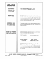
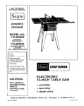
Save This Manual For
Future Reference
o wr_ers
manual
MODEL NO.
113.298760
SAW WITH LEGS
TWO CAST IRON
TABLE EXENSIONS
MOTOR AND
QUICK RELEASE
RIP FENCE
i,j_ll j,
_lt_,,_,IH,
!1'! !1"
Serial
Number
Modeland serial numbermay be found
at the left-hand side of the base
You should record both model and
serial number in a safe place for future
use
104NCH TABLE SAW
FOR YOUR
SAFETY:
. assembly
ooperating
, repair parts
READ ALL
INSTRUCTIONS
CAREFULLY
Sold by SEARS,
Part No,, SP5415
ROEBUCK
AND CO., Chicago,
IL. 60684 U.S.A.
Printed in USA.
FULL
ONE YEAR WARRANTY
ON CRAFTSMAN
TABLE
SAW
If within one year from the date of purchase, this Craftsman Table Saw fails due to a defect in
material or workmanship, Sears will repair it, free of charge This warranty applies only while
this product is in use in the United States.
WARRANTY SERVICE IS AVAILABLE BY SIMPLY CONTACTING
]'*HE NEAREST SEARS
SERVICE CENTER/DEPARTMENT
THROUGHOUT
THE UNITED STATES
This warranty gives you specific legal rights, and you may also have other rights which vary
from state to state_
SEARS, ROEBUCK
AND CO:, DepL 698/731A,
SAFETY iNSTRUCTiONS
Safety is a combination of common sense, slaying
alert and knowing how your table saw works Read
this manual to understand this saw..
Learn the use and function of the ON-OFF switch,
guard, spreader, anti-kickback device, miter gauge,
fence, table insert and blade elevation and bevel
controls. (See page 22)
7. NEVER STAND ON TOOL Serious injury could
occur if the tool tips or you accidentally
hit the
cutting tool Do not store anything above or near'
the tool where anyone might stand on the tool to
reach them
3 Review and understanding of all safety instructions
and operating procedures in this manual,,
BEFORE EACH USE:
methods for this saw.
1 Inspect your saw
a To avoid injury from accidental starting, unplug
the saw, turn the switch off and remove the
switch key before raising or removing the
guard, changing the cutting tool, changing
the setup or adjusting anything
b. Check for alignment of moving parts, binding
of moving parts, breakage of parts, mounting,
and any other conditions that may affect the
way it works If any part is missing, bent, or'
broken in any way, or arty electrical parts don't
work properly, turn the saw off and unplug the
(See page 41)
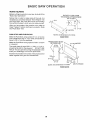
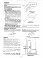
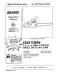
Read the following DANGER label found on the front of
the saw:
I!
USE
R_,_P
OWNERS
MANUAL
BEFORE
OPERATtNG
MACHtNE
_i _KNQW _,OW TO AVQ_D "K_C KUAC K$ =
I DAN E" t FO.O0"OW.SAFETY:
SAWOLADIE
'_A_D$
GUARD
OUT
OF
USE A ' PUS;" 5TIC_"
WARNING:
FOR
PATH
"_HRU
OF
5AW_HG
6
SAW'LADE
t
DO
NG'
NEVER
PErFOrM
_A_H
OPEFkAt_ONS
AAQ_JND
OR
" FRt_EHARD
OV[ft
•
5AWtJLA_3E
WHEN REQUIRED
u_E
_;_o
rOt.T. ,_, AUP
[IRANC,t
CIRt_U,,
AND
t_SE
_
AMP
,_ME
_ELAY
FOR TABLE SAW
5 To avoid injury from electrical shock, make sure
your fingers do not ,DUCt1the plug's metal prongs
when plugging in or' unplugging the saw..
6. To avoid back injury, get help or use recommended casters when you need to move the saw.
Always get help if you need to lift the saw, Hold
the saw close to your body Bend your knees so
you can lift with your legs, not your back.
WARNING:
To avoid mistakes that could cause
serious, permanent injury, do not plug the saw in
until the following steps have been satlsfactorily
completed.
1_ Assembly and alignment (See pages 9 - 21).
READ AND UNDERSTAND
WEA_I$AF_T'tGOGG_,ES
IL 60684
ed for 120 volt 15 amp circuits
The green
conductor in the cord is the grounding wire. To
avoid electrocution,
NEVER connect the green
wire to a live termina!
BEFORE USING THE SAW:
4. Review of the maintenance
Sears Tower, Chicago,
FUf_
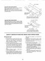
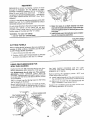
WHEN INSTALLING OR MOVING THE SAW:
1. AVOID DANGEROUS ENVIRONMENT., Use the
saw in a dry place protected from r'ain..Keep work
area well lighted,
2_ To avoid injury from unexpected saw movement:
a Put the saw on a firm level surface where there
is plenty of room for handling and properly
supporting the workpiece..
b, Support the saw so the table is level and the
saw does not rock.
c. Bott the saw to the floor if it tends to slip, walk,
or slide during normal use_
d_ When using table extensions over 24" wide on
any side of the saw, bolt the saw to the floor or
prop up the outer' end of the extension from
the floor' to keep the saw from tipping.
3. Put the saw where neither operators or bystanders must stand in line with the saw blade_
4 GROUND THE SAW - This saw has an approved
3-conductor cord and a 3-prong grounding type
plug, The plug fits grounding type outlets design-
saw,
c. Replace damaged, missing, or failed parts
before using the saw again
d. Use the sawblade guard, spreader, and antikickback pawls for any thru-sawing (wher]ever
the blade comes through the top of the workpiece). Make sure the pawls work properly.
Make sure the spreader is in line with the
sawblade.
e_REMOVE
ADJUSTING
KEYS
AND
WRENCHES
Form habit of checking for and
removing keys and adjusting wrenches from
tool before turning it on.
f. To avoid injury from jams, slips or thrown pieces
(kickback and throwback):
1. USE ONLY RECOMMENDED
ACCESSO*
RIES° Follow the instructions that come with
the accessories Consult the owner's manual
for recommended accessories. The use of
improper accessories may cause risk of injury
to persons.
2
2. Choose the right blade orcutting accessory
for the material and the type of cutting you
plan to do
3 Never use grinding wheels, abrasive cut-off
wheels, friction
wheels (metal slitting
blades) wire wheels or buffing wheel They
can fly apart explosively.
4 Choose and inspect your cutting tool carefully.
a To avoid cutting tool failure and thrown
shrapnel (broken pieces of blade), use
only 10" or smaller blades or other cutting
tools marked for speeds of 3450 rpm or
higher.
b. Always use unbroken, balanced blades
designed to fit this saw's 518" arbor
c When thru-sawing,
(making cuts where
the blade comes through the workpiece
top) always use a 10 inch diameter blade.
This keeps the spreader in closest to the
blade.
d Do not overtighten arbor nut. Use arbor
wrenches to "snug" it securely,
e. Use only sharp blades with properly set
teeth Consult a professional bladesharpener when in doubt..
f Keep blades clean of gum and resin.
5.. Adjust table inserts flush with the table top
NEVER use the saw without the proper
insert,
6 Make sure all clamps and locks are tight
and no parts have any excessive play
2, KEEP WORK AREA CLEAN
a. Cluttered areas and benches invite accidents
Floor must not be slippery
from wax or
sawdust
b To avoid burns or other fire damage, never use
the saw near flammable liquids, vapors or
gases
Plan ahead to protect your eyes, hands, face,
ears
a.. To avoid injury, don't do layout, assembly, or
setup work on the table while the blade is
spinning. It could cut or throw anything hitting
the blade.
AVOID ACCIDENTAL
STARTING - Make sure
switch is "OFF" before plugging saw in
Plan your work
1 USE THE RIGHT TOOL - Don't force toot or
attachment to do a job it was not designed for..
2 Dress for safety:
- Do not wear loose clothing, gloves, neckties
or jewelry (rings, wrist watches). They can get
caught and draw you into moving parts,
- Wear nonslip footwear
- Tie back long hair.
- Roll long sleeves above the elbow
- Noise levels vary widely. To avoid possible
hearing damage, wear ear plugs or muffs
when using saw for long periods of time
Any power saw can throw foreign objects into
the eyes This can cause permanent
eye
damage Wear safety goggles (not glasses)
that comply with ANSI Z87..1 (shown on package).. Everyday eyeglasses have only impact
resistant lenses. They are not safety glasses.
Safety goggles are available at Sears retail
catalog stores. Glasses or goggles not in
compliance with ANSI Z87 1 could seriously
hurt you when they break
WEAR
YOUR
- For dusty operations, wear a dust mask along
with the safety goggles
3 Inspect your workpiece.. Make sure there are no
nails or foreign objects in the part of the workpiece to be cut.
4. Plan your cut to avoid KICKBACKS and THROWBACKS - when a part or all of the workpiece
binds on the blade and is thrown violently back
toward the front of the saw:
Never cut FREEHAND: Always use either a rip
fence, miter gauge or fixture to position and
guide the work, so it won't twist, bind on the
blade and kickback
Make sure there's no debris between the
workpiece and its supports
When cutting irregularly shaped workpieces,
plan your work so it will not slip and pinch the
blade:
- A piece of molding, for example, must lie
flat or be held by a fixture or jig that will not
let it twist, rock or slip while being cut.. Use
jigs, fixtures where needed to prevent workpiece shifting
- Use a different, better suited type of tool for
work that can't be made stable.
- Use extra caution with large, very small or
awkward workpieces:
-Use extra supports (tables, saw horses,
blocks, etc..) for any workpieces
large
enough to tip when not held down to the
table top. NEVER use another person as a
substitute for a table extension, or as additional support for a workpiece that is longer
or wider then the basic saw table, or to help
feed, support or pull the workpiece.
- Never confine the piece being cut off That
is, the piece NOT against the fence, miter
gauge or fixture. Never hold it, clamp it,
touch it, or use length stops against it. It
must be free to move If confined, it could
get wedged against the blade and cause a
kickback or throwback
- Nevercut morethan one workpieceat a
time
-Never turn your table saw "ON" before
clearingeverythingexceptthe workpiece
andrelatedsupportdevicesoff the table.
Plan the way you will push the workpiece through.
-NEVER pull the workpiece through Start and
finish the cut from the front of the table saw.
- NEVER put your fingers or hands in the path of
the sawblade or other cutting tool..
-NEVER reach in back of the cutting tool with
either hand to hold down or support the workpiece, remove wood scraps, or for any other
reason..
- Avoid hand positions where a sudden slip could
cause fingers or hand to move into a sawblade or
other cutting too!
- DON'T OVERREACH Always keep good footing
and balance
- Push the workpiece against the rotation of the
blade NEVER feed material into the cutting tool
from the rear' of the saw.
- Always push the workpiece
sawblade
all the way past the
- As much as possible, keep your face and body to
one side of the sawblade, out of line with a
possible kickback or throwback.
- NEVER turn the saw "ON" before clearing the
table of all tools, wood scraps, etc, except the
workpiece and related feed or support devices
for the cut planned
c Wait for all moving parts to stop
d Check blade, spreader and fence for proper
alignment before starting, again..
8 To avoid throwback of small, cut off pieces:
a Use the guard assembly
b To remove pieces trapped inside the guard:
1 Turn saw off
2.. Remove switch key
3 Unplug saw
4. Wait for blade to stop before
guard
additional instructions
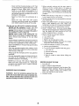
RiP TYPE CUTS
b Unplug
the saw
for
- A FEATHERBOARD
can help guide the workpiece. See BAStC SAW OPERATION - USING
THE RIP FENCE. Always use featherboards for
any non-thru rip type cuts.
_,____i___24"
_I
5/I 6" APART
4-1/2""_
1 Before actually cutting with the saw, watch it
while it runs for a short while, if it makes an
unfamiliar noise or vibrates a tot, stop immediately. Turn the saw off. Unplug the saw Do not
restart until finding and fixing the problem
2. Make sure the top of the arbor-or cutting tool
turns toward the front of the saw
3. Set the cutting tool as low as possible for the cut
you're planning
4, KEEP CHILDREN AWAY All visitors should be
kept a safe distance from work. Make sure
bystanders are clear of the saw and workpiece
5 Let the blade reach full speed before cutting
6. DON'T FORCE TOOL. tt will do the job better
and safer at its designed rate.. Feed the workpiece
into the blade only fast enough to let it cut
without bogging down or binding
7. Before freeing any jammed material:
a Turn switch "OFF"..
the
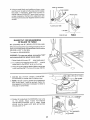
- NEVER use the miter gauge when ripping
- Use a push stick whenever the fence is 2 to 6
inches from the blade Use an auxiliary fence and
push block whenever' the fence must be within 2
inches of the blade. (See "Basic Saw Operation
Using The Rip Fence" section)
- Never-rip anything shorter than 10" long
-When using a push stick or push block, the
trailing end of the board must be square A push
stick or block against an uneven end could slip
off or push the work away from the fence..
WHENEVER SAW IS RUNNING
WARNING:
Don't let familiarity (gained from frequent use of your table saw) cause a careless mistake. Always remember that a careless fraction of a
second is enough to cause a severe injury.
lifting
_-_
Before Starting
-To avoid kickbacks and slips into the blade,
make sure the rip fence is paratlel to the sawblade
Check the antikickback pawls. (See BASIC SAW
OPERATION - USING THE RIP FENCE) The
pawls must stop a kickback once it has started,
Replace or sharpen antikickback
pawls when
points become dull.
- Plastic and composition
(like hardboard) materials may be cut on your saw However, since
these are usually quite hard and slippery, the
antikickback
pawls may not stop a kickback,
Therefore, be especially careful in your set-up
and cutting procedures..
While cutting
-To avoid kickbacks and slips into the blade,
always push forward on the section of the workpiece between the saw blade and the rip fence
Never push forward on the piece being cut off
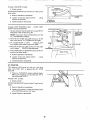
additional instructions for
CROSS CUT TYPE CUTS
While cutting
Before starting
- NEVER use the rip fence when crosscutting
An auxiliary wood facing attached to the miter
gauge can help prevent workpiece twisting and
throwbacks.
Attach it to the holes provided..
Make the facing long enough and big enough to
support your work. Make sure, however, it will
not interfere with the sawbtade guard.
- Use jigs or fixtures to help hold any piece too
small to extend across the full length of the miter
gauge face during the cut This lets you properly
hold the miter gauge and workpiece and helps
keep your hands away from the blade.
GLOSSARY
- To avoid blade contact, always hold the miter
gauge as shown in the BASIC SAW OPERATIONS - USING THE MITER GAUGE
BEFORE LEAVING THE SAW
1. Turn the saw off
2. Wait for blade to stop spinning
3. Make workshop child-proof
Lock the shop. Disconnect master switches. Remove the yellow
switch key. Store it away from children and
others not qualified to use the tool
4 Unplug the saw.
OF TERMS FOR WOODWORKaNG
Anti-Kickback
Pawls (AKB)
Device which, when properly maintained, is designed to stop the workpiece from being kicked back at
the operator during ripping operations
Arbor
The shaft on which a cutting tool is mounted
Crosscut
A cutting or shaping operation made across the
width of the workpiece
Dado
A non-through cut which produces a square sicted
notch or trough in the workpiece.
Featherboard
A device which can help guide workpieces during rip
type operations
Freehand
Performing a cut without using a fence, miter gauge,
fixture, hold down or other proper device to keep the
workpiece from twisting during the cut
Gum
A sticky, sap based residue from wood products
Heel
Misatignment of the blade
Kerf
The amount of material removed by the blade in a
through cut or the slot produced by the blade in a
non-through or partial cut..
Kickback
An uncontrolled grabbing and throwing of the workpiece back toward the front of the saw during a rip
type operation
Leading End
The end of the workpiece which, during a rip type
operation, is pushed into the cutting tool first
Molding
A non-through cut which produces a special shape
in the workpiece used for joining or decoration
Push Stick
A device used to feed the workpiece through the saw
during narrow ripping type operations
and help
keep the operator's hands welt away from the blade.
Push Block
A device used for ripping type operations too narrow
to allow use of a push stick
Rabbet
A notch in the edge of a workpiece
Resin
A sticky, sap base substance that has hardened
Ripping
A cutting operation along the length of the workpiece.
Revolutions Per Minute (RPM)
The number of turns completed by a spinning object
in one minute
Sawbiade Path
The area of the workpiece or table top directly in line
with the part of the workpiece which will be, or has
been, cut by the blade
Set
The distance that the tip of the sawblade tooth is
bent (or set) outward from the face of the blade.
Throw-Back
Throwing of pieces in a manner similar to a kickback
Thru*Sawing
Any cutting operation where the blade extends
completely through the thickness of the workpiece
Trailing End
The workpiece end last cut by the blade in a ripping
operation
Workpiece
The item on which the cutting operation is being
done The surfaces of a workpiece are commonly
referred to as faces, ends, and edges
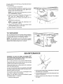
MOTOR
SPECRFtCATDONS AND ELECTROCAL REQUIREMENTS
This saw is designed to use a 3450 RPM motor only.. Do
not use any motor that runs faster than 3450 RPM. It is
wired for operation on 120 volts, 60 Hz. alternating
current. IT MUST NOT BE CONVERTED TO OPERATE ON 230 VOLTS°
If,the outlet you are planning to use for' this saw is of the
two prong type DO NOT REMOVE OR ALTER THE
GROUNDING PRONG IN ANY MANNER
Use an
adapter as shown and always co nnect the grounding tug
to a known ground
CAUTION: Do not use blower' or washing machine
motors or any motor with an automatic reset over'toad protector as their use may be hazardous.
For
replacement motor refer to parts list in this manual.
It is recommended that you have a qualified electrician
replace the TVVO prong outlet with a properly grounded
THREE prong outlet.,
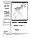
CONNECTING
A temporary adapter, as shown below, is available for
connecting plugs to 2-prong receptacles° The green
grounding lug extending from the adapter must be connected to a permanent ground, such as to a properly
grounded outtet box..
TO POWER SOURCE OUTLET
This saw must be grounded while in use to protect the
operator from electrical shock.
If power cord is worn or cut, or damaged in any way, have
it replaced immediately
Your saw is for use on 120 volts and has a plug that looks
like the one below..
3-PRONG
A temporary adapter, as illustrated, is available for connecting plugs to 2-prong receptacles. The temporary
adapter should be used only until a properly grounded
outlet can be installed by a qualified electrician
GROUNDING
PLUG
LUG
_
.Loo
3-PRONG
__
f
_-
MAKE
t_
SURE
THIS
IS
.NOW.
GROUND
CONNECTED
TO
A
®
GROUNDING
/
PRONG
RECEPTAO'E
ADAPTER
.Y
3-PRONG
GROUNDED
OUTLET
WARNING:
The green grounding lug extending
from the adapter must be connected to a permanent
ground such as to a properly grounded outlet box.
Not all outlet boxes are properly grounded.
Plug power cord of fully assembled saw into 120V
properly grounded type outlet protected by a 15-amp
time delay or Circuit-Saver fuse or circuit breaker.
If you are not sure that your outlet box is properly
grounded, have it checked by a qualified electrican
If you are not sure that your outlet is properly
grounded, have it checked by a qualified electrician.
NOTE: The adapter illustrated is for use only if you
already have a properly grounded 2-prong receptacle.
WARNING:
Do not perm'it fingers to touch
terminals of plug when installing or removing
plug to or from the outlet,
the
the
The use of any extension cord wilt cause some loss of
power. To keep this to a minimum and to prevent overheating and motor burn-out, use the table below to
determine the minimum wire size (A.,W.G) extension
cord., Use only 3 wire extension cords which have 3
prong grounding type plugs and 3-pole receptacles
which will accept the plug on the saw.
WARNING: If not properly grounded this power tool
can incur the potential hazard of electrical shock
particularly when used in damp locations, in proximity to plumbing, or out of doors_ if an electrical
shock occurs there is the potential of a secondary
hazard such as your hands contacting the sawblade.
Extension Cord Length
Wire Size A.W,G.
0-25 Ft ..........................
26-50 Ft ......................
51-100 Ft .......................
This saw is equipped with a 3-conductor cord and
grounding type plug which has a grounding prong,
approved by Underwriters' Laboratories and the Canadian Standards Association. The ground conductor has
a green lug and is attached to the tool housing at one end
and to the ground prong in the attachment plug at the
other' end,_
CHECK
MOTOR
16
14
12
ROI"ATION
WARNING: For your own safety, make sure plug is
not connected to power source outlet when changing motor rotation.
This plug requires a mating 3-conductor grounded type
outlet as shown.
Tt}e motor must rotate CLOCKWISE when viewed from
the shaft end to which you will mount the pulley If it does
not, change the direction according to the instructions
furnished with the motor..
6
CONTENTS
WARRANTY ...............................................................................
2
SAFETY iNSTRUCTIONS FOR TABLE SAWS ..............
2
Removing and Installing Sawblade ....................... 24
Exact-l-Cut ......................................................................
24
BASIC SAW OPERATION ................................................
25
Rip Type Cuts ...............................................................................
4
Work Helpers ...............................................................25
Cross Cut Type Cuts ..............................................................
5
GLOSSARY OF WOODWORKING TERMS .....................
5
Safety Instuctions for Basic Saw Operatiori ....... 26
MOTOR SPECIFICATIONS AND ELECTRICAL
Using the Miter Gauge ................................................29
REQUIREMENTS ..........................................................6
Crosscutting ........................................................ 29
UNPACKING AND CHECKING CONTENTS ...............7
Repetitive Cutting ..................................................30
Tools Needed ........................................................................
7
Miter Cutting ............................................................30
List of Loose Parts .................................................................
8
Bevel Crosscutting ..................................................
3i
ASSEMBLY ........................................................................................
9
Compound Miter Cutting .......................................31
Installing Handwheels .................................................................
9
Using the Rip Fence ..........................................................
31
Checking Table Insert ......................................................
9
Ripping ............................................................................
32
Checking Blade Squareness to Table .............................
9
Bevel Ripping ..........................................................
32
Using Featherboards for Thru-Sawing ............. 32
Assembling Steel Legs ..........................................................
10
Mounting Saw ..................................................................................
10
Resawing .........................................................................
35
Cutting Panels .........................................................
35
Attaching Table Extensions ............................................
1t
Using Featherboards lot Non-Thru Sawing .....35
Mounting Switch .....................................................................
12
Rabbeting .......................................................................
36
Installing Rip Fence Guide Bars .................................
12
Aligning Rip Fence ..................................................................
14
Ploughing and Molding ................................... 36
Adjusting Rip Scale Pointer ..........................................
16
Dadoing ..................................................................36
Molding Cutting ..........................................................
37
Installing Blade Guard .....................................................
16
ADJUSTMENTS ................................................................................
37
Mounting the Motor .............................................................
18
Miter Gauge ............................................................... 37
Installing Belt Guard .............................................................
20
Plugging in Motor ..........................................................
21
Heeling Adjustment or Parallelism of Sawblade
GETTING TO KNOW YOUR SAW ................................
22
to Miter Gauge Groove ...................................... 38
On-Off Switch ........................................................................
22
Blade Tilt or Squareness of Blade to Table ..........39
Elevation Handwheel ....................................................
23
Tilt Mechanism ........................................................ 41
Tilt Handwheel .....................................................................
23
MAINTENANCE ......................................................... 41
Tilt Lock Handle ...................................................................
23
LUBRICATION .................................................................42
RECOMMENDED ACCESSORIES ......................... 42
Rip Fence ..........................................................................
23
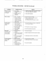
TROUBLESHOOTING
................................................ 43
Miter Gauge ..................................................................
23
Blade Guard ........................................................................................
23
REPAIR PARTS ............................................................ 45
Table insert ........................................................................
23
UNPACKaNG
AND CHECKONG CONTENTS
TOOLS NEEDED
COMBINATION
SQUARE
MUST
STRAIGHT
3/4" THICK,
Medium Screwdriver
Small Screwdriver
DRAW
BOARD
LIGHT
ALONG
LINE
THIS
ON
BE
EDGE
*'_',,',
BE
TRUE,
EDGE
THIS
PERFECTLY
OF BOARD
EDGE
MUST
STRAIGHT
_
t
_-')__r_
Ptler
18
iWrencTh;16
1/2 in.
Combination
Square
f
L
@
/
9/16 ino
3/4 in,
SHOULD
BE NO GAP OR OVERLAP
HERE WHEN
SQUARE
OVER
IN DOTTED
Separate ait parts from packing materials and check
each one with the illustration and the list of Loose Parts
to make certain all items are accounted for, before
discarding any packing material.,
IS FLIPPED
POSITION
WARNING: To avoid fire or health hazard, never use
gasoline, naptha or similar highly volatile solvents,
WARNING: To avoid injury, if any parts are missing,
do not attempt to assemble the table saw, plu g In the
power cord or turn the switch on until the missing
parts are obtained and are installed correctly.
Apply a coat of automobile wax to the table
Wipe all parts thoroughly with a clean, dry cloth.
WARNING: Foryour own safety, never connect plug
to power source outlet until all assembly steps are
complete, and you have read and understand the
safety and operational instructions,
Remove the protective oil that is applied to the table top
and edges of the table,, Use any ordinary household type
grease and spot remover,
7
®
Y
AA
S_ZE
©
AB
AC
Ao'_
AF
AN
AK
AL
AJ
AM
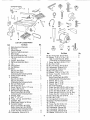
LIST OF LOOSE PARTS
Item
Part Name
A
B
C
D
E
F
J
Blade Guard and Spreader. ...............
Rip Fence .......................................
Owners Manual ............................
Cast hon Table Extensions ..................
Miter Gauge .................................
Rip Fence Guide Bar Rod .................
Rip Fence Guide Bar with Rip Scale
(Front) ......................................
Support, Motor Base .........................
Rip Fence Guide Bar (Rear) ..................
Leg .......................................
Side Stiffener ....................................
End Stiffener ..............................
Motor. .......................................
Bag of Loose Parts ........................
Bag of Loose Parts
(Containing the Following Items)
Outlet, OnlOff with Key ....................
Handwheel .................................
Bag of Loose Parts .........................
Bag of Loose Parts
(Containing the Following Items)
Belt and Pulley Guard ........................
Belt Guard Clip "S" . .....................
Screw, Pan Hd. 10-32 x If2" Long ...........
Support, Belt Guard .........................
Belt Guard Support Bracket ..................
Bag of Loose Parts No. 62750
(Containing the Following Items)
Wrench, Arbor. ...............................
Belt, "V" 1f2" x 41". ...........................
Puiley, ti2" dia with 518" Bore ..............
Spreader, Rod ..............................
Blade Guard SupportwtScrew
...........
Spreader Support ..............................
Bag of Loose Parts No 62751 ..............
Bag of Loose Parts No. 507780
(Containing the Following Items)
Screw, Hex Hd 5tt6-18 x t-1f4 ............
Lockwasher, External 5t16 ..................
S
V
AJ
AK
AL
AM
H
K
N
0
P
Q
R
G
L
M
T
U
W
Z
AB
Qty.
t
t
1
2
1
1
1
t
1
4
2
2
1
2
I
2
3
1
3
3
1
1
1
1
1
1
1
1
t
8
8
AN
AO
Item
P_rt Name
AN Nut, Heavy Hex Jam 5116-18 .................
AO Washer. 11f32 x 11f16 x 1t16 ............
Z
AA
AA
AB
AB
AN
A0
AP
AQ
X
X
X
Y
Z
Z
Z
AA
AA
AC
AD
AE
AF
AG
AB
AB
AB
AO
gty,
8
8
Bag of Loose Parts No 62752
(Containing the Following Items)
Screw, Hex Hd. 5116-18 x 1-1f4 ...........
4
Nut, Hex 114-20 ...............................
24
Nut, Hex Heavy Jam 5/16-18 .............
4
Lockwasher, External 5/16 ...................
4
Lockwasher, External 1!4 .....................
24
Nut, Hex Jam 1t2-t3 ........................
8
Washer, 11/32 x 11/16 x 1/16 .............
8
Screw, Truss Hd. 1/4-20 x 5/8 ............
24
Foot, Leveling 1f2 ...........................
4
Bag of Loose Parts No. 62751
(Containing the Following Items)
Wrench, Hex "L" 118 .......................
1
Wrench, Hex "L" 3f32 .....................
1
Wrench, Hex "L" 5/32 .......................
1
Nut, Self-Threading .....................
2
Screw, Hex Hd, 5/16-18 x 5/8 in, long .....
3
Screw, Hex Hd 5/!6-18 x 3/4 in. long .....
2
Screw, Hex Hed. 5/16-18 x 1 in long ......
4
Screw, Hex Hd. 5/16.18 x 1-3/4 in long .... 2
Screw, Hex Hd. t/4-20 x 5/8 in long ......
2
Nut, Heavy Hex Jam 5f16-18 ...............
10
Nut, Hex 114-20 ..........................
2
Carriage Bolt, 5f16-18 x 3f4 ............
4
Spacer, Rip Fence Guide Bar ................
2
Tie Wire .................................
2
Screw, Pan Hd. 10-32 x 3f4 .................
2
Screw, Thumb 5f!6-18 x I ..................
1
Lockwasher, External #10 ..................
2
Lockwasher, External If4 ...................
2
Lockwasher, External 5f16 ...............
12
Washer, 21f64 x 5t8x tt16 ................
2
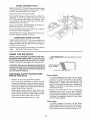
ASSEMBLY
Before mounting the saw on legs, a stand or a bench,
the Table Insert and Blade Squareness must be
checked at this time..
LOCKWASHER
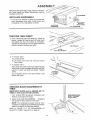
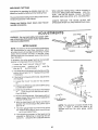
INSTALLING
HANDWHEELS
1. Line up FLAT SPOTS on shaft and hardwheei,
push handwheel onto shaft. Install screw and
Iockwasher to lock handwheel on shaft..
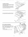
10-32 x 3/4 IN,
PHILLIPS
HEAD SCREW
ELEVATION
HANDWHEEL
CHECKING
TABLE
TILT HANDWHEEL
INSERT
2. insert should be flush with table top. Check as
shown. Loosen flat head screw that holds insert
and adjust the four set screws as necessary.
Tighten flat head screw. Do not tighten screw to
the point where it deflects the insert..
SETSCREW
WRENCH
3. To remove insert..
A) Loosen Screw
B) Lift insert from front end, and pull toward
front of saw.
4 To replace insert.
Place insert into insert opening in table and push
toward rear of saw to engage spring clip and until
keyslot in insert will drop over screw Tighten
screw.
Do not tighten screw to the point where it will
deflect the insert
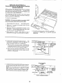
CHECKING
TABLE
BLADE SQUARENESS
TO
IMPORTANT:
BLADE must be SQUARE (90 ° ) to
TABLE, in order to proceed with assembly.
1_Turn ELEVATION handwheel clockwise
blade is up as high as it will go..
until
MAKE SURE SQUARE
IS NOT TOUCHING
TiP OF TOOTH
2. Check for BLADE SQUARENESS ..... if blade is
not square to table, adjust it at this time.
NOTE: The combination square must be "true"
-see start of "Unpacking and Checking Contents"
section on page 6 for checking method..
Refer to "BLADE TILT, OR SQUARENESS
OF
BLADE TO TABLE" adjustment on page 34
9
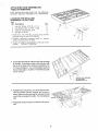
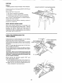
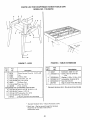
ASSEMBLING
STEEL LEGS
From among the loose parts, find
Hardware:
the following
24 Truss Head Screws, 1/4-20 x 5/8 in, long (top of
screw is rounded)
ASSEMBLE
SCREWS
THROUGH
HOLES
MARKED
"X"
24 Lockwashers,
1/4 in., External Type (approx
dia,. of hole 1/4 in..)
24 Hex Nuts, 1/4-20 (approx. dia of hole 1/4 in.)
8 Hex Nuts, 1/2-13 (approx. dia_ of hole 1/2 in..)
4 Leveling feet
Assemble
_
SIDE
STIFFENER
the legs as shown ....
END
STIFFENER
1 insert the Truss Head Screws through the holes
in the legs, then through the holes in the stiffeners MAKE SURE THE SCREWS TO THROUGH
THE HOLES
IN THE SIDE STIFFENERS
MARKED "X"
\
2._Install the Iockwashers ..... screw on the nuts but
do not tighten until completely assembled
, 1/2 IN,
3._Install leveling feet.
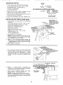
MOUNTING
HEX
NUTS
SAW
I. From among the loose parts, find the following
hardware:
4 Hex Head Screws, 5/16-18 x 1-1/4 in Iongo
4 Hex Nuts, 5/16-18 (approx. dia._of hole 5/16 in )
4 Lockwashers, 5/16 in. Externa! Type (approx.
dia of hole, 5/16 in.)
8 Flat Washers, (dia. of hole 11/32 in.)
2. Plase saw on legs so that holes in bottom of saw
Jine up with holes in top of legs..
3. Install screws, washers, Iockwashers and nuts as
shown.
If you mount the saw on any other' bench, make sure
that there is an opening in the top of the bench the
same size as the opening in the bottom of the saw so
that the sawdust can drop through Recommended
working height is 33 to 37 inches from the top of the
saw table to the floor.
SAW
WASHER
11-I14
BASE
HEX
HEAD
SC. W
FLAT
7/16 DIA. HOLES
13
I
._.Jj
END
FLAT WASHER
LOCKWASHER
--'-"
-'f_'__
HEXNUT
STIFFENER--,'-!
1
2-3/4
NOTE: All dimensions
10
in inches
, i__¸¸" ;
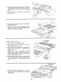
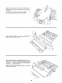
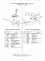
ATTACHING
AND ASSEMBLING
TABLE EXTENSIONS
From among the loose parts find the following
hardware: (Quantity indicated is for 2 extensions)
HARDWARE FOR INSTALLING
EXTENSIONS TO SAW TABLE
Ref,
No,
1
2
3
4
I
Description
Hex Hd Screw, 5/16-18 x 1-1/4 ......
Flat Washer (Dia of Hole t!/32)
....
External Lockwasher, 5/t6
..........
Hex Nut, 5/16-18 ......................
Insert four (4) 5/t6-t8
through
holes in each
x 1-1/4 in
EXTENSION
long
Qty.
8
8
8
8
screws
3
2 Position
extension
against
table
so screws
extend through
holes in table
3 _nstall flat washer, Iockwashers,
and nuts on the
screws
DO NOT TIGHTEN
4
4 Line up the rear edge of extension with the rear edge
of the table=, Line up top su trace of the extension with
the top of the table at the locations indicated by the
"X"s (see illustration),. Use a combination square to
line-up these edges SLIGHTLY TIGHTEN nuts with
a 9/16" wrench
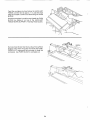
CHECK
WITH
SQUARE
AT 2 PLACES
MARKED
WITH "X"
.,
6_
If adjustment is necessary, you should tap the extension into position using a hammer and a block of
woo& Make sure the rear edge of extension is lined
up with the rear edge of the table, Then firmly tighten
nuts r
BLOCK OF WOOD
Repeat the same procedure to install the other extension,,
11
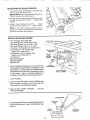
MOUNTING
t
SWITCH
JAM NUT
5/16-18
1
From among loose parts find the following:
2 Hex Head Screws, 5/16-18 x 3/4 in. long
2 Flatwashers (dia. of hole 21/64 in )
2 External Lockwashers
2 Hex Nuts, 5/16-18
2 Insert two 3/4 inch screws through
washers then through holes in switch.
,@ ,_
(_
two flat
10TH
iLOCKWASHER
\_
\
• 8TH
t_\
HOLE
_ _\
_
_,L_JL_
3 Insert screws through holes eight and ten in front
fence guide bar as illustrated.
4 tnstall two lockwashers
INSTALLING
and nuts Tighten
RIP FENCE
GUIDE
HOLE
FRONT
FENCE
GUIDE
BAR
(UPSIDE
DOWN)
HEX HEAD
SCREW
5/16-18
x 3/4 IN_
nuts
BARS
1. From among tile loose parts find the following
hardware:
7TH
2 Hex Head Screws, 5/16-18 x 1-3/4 in long
2 Hex Head Screws, 5/16-18 x 1 in. long
4 External Lockwashers, 5/16 in
(approx dia. of hole 5/16 in )
4 Hex Nuts, 5/16-18
(approx dia. of hole 5/16 in.)
2 Spacers, 3/4 in. dia x 1/2 in long
2 Self-threading
nuts
1 Fence Guide Bar Rod
HOLE
3RD
HOLE
LEFT SIDE OF
FRONT
GUIDE
BAR
(GUIDE
BAR IS TO BE
TURNED
END FOR END
AFTER
SCREWS
ARE
INSTALLED)
HEX HEAD
SCREW
5/16-18
x I-3/4
2 Lay guide bars on saw table.
NOTE: The various holes in the bar allows them
to be positioned on this saw and also makes
them adaptable to other models
IN,
3 insert a 1-3/4 inch long screw through the
THIRD hole IN THE FRONT BAR as illustrated
Insert another 1-3/4 inch long screwthrough
ihe SEVENTH hole in bar.
4. Place spacers
on screws
5 Turn front bar end for end and insert bolts
through holes in middle and on right sides of
front of saw table as illustrated
.
instalt
tockwashers and nuts DON'T SCREW NUTS
ON ALL THE WAY, just get them started on the
SCr ews
_'_" SELF-TH R E ADIN G NUT
.
\
6 Insert 1 in long screws in SECOND and
FOURTH or FIFTH holes of rear bar and attach
to table the same way as front bar
7. Insert ends of FENCE GUIDE BAR ROD
through holes in bars as illustrated
NOTE: The ends of the ROD are not threaded ....
the SELF THREADING
NUTS will cut threads
on the rod as they are screwed on Just start nuts
onto ends of rod
FENCE
BAR
12
GUIDE
ROD
4TH OR 5TH
HOLE
2ND
HOLE
8. Holdrodwithonehandandwitha I/2 in,,wrench
or pliersstartscrewingonONEofthenutsonlyA
TURNORTWO. screwon othernut thesame
way.
9, Using TWO1/2 in. wrenchesor pliers tighten
bothof the nuts.
10,Slidethe barsso thatscrewsarein the MIDDLE
of the slottedholes.
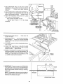
1I. Position rip fence over miter gauge groove,
holdinguptherearendwhileengagingfrontend
with bar lowerfenceontotable,
8 THICKNESSES
OF PAPER
12,,Raisebladeall the wayup,
13.Carefullymovefenceagainstblade,
14.Movefront bar until "0" mark on rip scaleis
approximatelyat tip of pointer,
15,MoveFRONTbarupwardsuntilfenceisapproximatelyt/32 in, abovetable . . tighten screw at
left end of bar
NOTE: Fold a piece of newspaper making 8
thicknesses and place between rip fence and
table to act as a spacer. This will hold the fence
off of the table approx 1/32 in.
16, Adjust rear bar so that the fence is approximately
1/32 in., above table make sure it is square with
fence guide bar rod..,
tighten screw at end of
bar.
17. Move fence to RIGHT edge of table. _. make sure
it is approx. 1/32 in. above table at front and rear and
tighten screws.
13
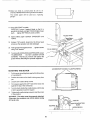
ALIGNING
RIP FENCE
The fence should slide easily along the bars and
always remain in alignment (parallel to sawblade
and miter gauge grooves),
The alignment is maintained by a spring underneath
the fence which bears against the front guide bar
To move the fence, loosen the lock handle and grasp
the fence with one hand at the front
For very close adjustments, grasp the guide bar-with
both hands and move the fence with your thumbs
SELF ALIGNING
ADJUSTMENT
Place fence on saw but DO NOT LOCK IT..
Move the R EAR END of the fence slightly to the right
or left , . when you release it, the fence should
"spring" back to its original position
If it does not, the spring
CREASED
pressure
must be IN-
1 Loosen the screws
2 Move Spring slightly
toward front of fence,.
14
If fence does not slide easily along the bars, the
pressure of the spring can be REDUCED
1 Loosen the screws
2, Move spring slightly
tighten screws,
toward
rear of fence
,
WARNING:
TO AVOID INJURY FROM JAMS OR
KICKBACK, BE SURE TO PROPERLY ADJUST AND
PUSH LOCK LEVER ALL THE WAY DOWN UNTIL
THE LEVER RESTS ON THE STOP BEFORE USING
THIS RIP FENCE.
SPRING
SLIDE
ADJUST
RIP FENCE
LOCK LEVER
SPRING
TO
PRESSURE
ADJUSTMENT
The rip fence lock lever when locked down, should hold
the rip fence securely, it should not be difficult to push
down and lock,
If lock lever does not lock fence securely
1 Raise lock lever.
.,
FENCE
HEAD
2. Tighten the adjusting nut using a small screwdriver
until the lever, when locked, holds the rip fence
securely
If lock lever is difficult Io push down
1,, Raise lock lever_
2.. Loosen the adjusting nut using a small screwdriver
until the lever is easy to push down and holds 1he rip
fence securely,,
RIP FENCE
ALIGNMENT
ADJUSTMENT
HEX
The rip fence must be PARALLEL with the sawblade and
Miter Gauge grooves.,, Move fence until it is along side
of groove, Do NOT LOCK IT, It should be parallel to
groove.. If it is not;
SCREWS
FENCE
1. Loosen the two "Hex Head Screws",
2,, Hold fence head tightly against bar, ,. move end of
fence so that it is parallel with groove.,
3, Alternately tighten the screws,
4 Recheck alignment,
5,, Repeat steps as needed.
15
HEAD
ADJUSTING
RIP SCALE
POINTER
Turn ELEVATION HANDWHEEL clockwise until
blade is up as high as it will go
IMPORTANT: BLADE must be SQUARE (90 °) to
TABLE, in order to ALIGN rip fence
LOCK HANDLE _-_
2. Position fence on right side of sawbtade so that it
touches the sides of the teeth
tighten lock
handle.
3 Loosen screw holding the pointer
. .. adjust
pointer so that it points to "0" .... tighten screw.
NOTE: If you cannot adjust pointer so that it
points to "0", loosen the screws holding the front
guide bar and move the guide bar,
INSTALLING
BLADE
GUARD
1 From among the loose pads, find:
2 Hex Head Screws, 1/4-20 x 5/8 in. long
3 Hex Head Screws, 5/16-18 x 5/8 in. long
2 Hex Head Screws, 5/16-18 x 1 in, long
2 Hex Nuts, 1/4-20 (approx. dia, of hole 1/4 in.)
2 Lockwashers, 1/4 in. External Type
(approx. dia. of hole 1/4 in.)
2 Lockwashers, 5/16 in. External Type
(approx. dia, of hole 5/16 in_)
1 Thumbscrew
BLADE
GUARD
SUPPORT
5/t6_18
X
_
5/B IN.
HEX HD..
SCREW
Blade Guard Support
Spreader Support
Spreader Rod
5/16 IN.,
LOCKWASHERS
2 Before installing the blade guard, you must check the
heeling adjustment (parallelism of sawblade to miter
gauge groove).. The procedure for making this check
and adjusting it are found in the"Adjustments" section
of this manual
Refer to "Heeling Adjustment or
Parallelism of Saw Blade to Miter Gauge Groove".,
5/t6-18 X 5/8 IN,.
HEX HD,. SCREWS
3. Lower the blade.
4 Screw the MOTOR BASE CLAMP SCREWS part
way into cradle. Screw the 5/16-18 x 5/8 inch Hex
Head screw into the blade guard support.
5 Attach BLADE GUARD
TIGHTEN SCREWS
SUPPORT .....
DO NOT
'THUMB SCREW_
6 insert SPREADER ROD into SPREADER SUPPORT
until pin fits into notch° Insert THUMBSCREW and
tighten it.
\ c,.To
16
L
suP o.T
7,. Slide SPREADER ROD into BLADE GUARD
SUPPORT until end of ROD is even with edge of
SUPPORT •
Tighten Hex Head Screw in
support,
8. Attach SPREADER to SPREADER SUPPORT so
that the edge of the spreader is even with the
edge of the spreader support . tighten screws,
9 Raise ANTIKICKBACK
PAWL (hold it in place
with a piece of masking tape)
. align spreader SQUARE to table
Tighten
SCREWS.,
both 5/t6-18
1/4_20 HEX
HD. SCREW
1/4 INo LOCKWASHER
1/4-20 HEX NUT
x 1 in,, HEX HEAD
SPREADER EDGE
EVEN WITH SPREADER
SUPPORT EDGE
END OF ROD
EVEN WITH EDGE
OF SUPPORT
5/16-18 X 1 IN.
HEX HD_ SCREWS
r
t0. Raise blade all the way up
square with table,
make sure it is
1t Raise Blade Guard
lift up both ANTIKICKBACK PAWLS .... insert one of the SETSCREW
WRENCHES in the notches to hold the pawls out
of the way.
I2
Lay blade of square or other straightedge
side of blade,
along-
I3, Loosen Hex Head Screw in BLADE GUARD
SUPPORT and move spreader so that it touches
blade of square .,, tighten screw.
14 NOTE: The spreader is now square with the table
and approximately in line with the sawblade, The
spreader requires further adjustment to align it
PARALLEL to the blade and in the MIDDLE of the
cut (KERF) made by the sawblade,
HEX HD,
SCREW
15..IMPORTANT: To work properly, the SPREADER
must always be PARALLEL to the sawblade and
adjusted so the cut workpiece will pass on either
side at the spreader without binding or skewing
to the side.
NOTE: The spreader is thinner than the width of
the cut (KERF) made by the sawblade by approximately six thicknesses of paper.
LOOKING
17
DOWN ON SAW
16 Make two folds in a small piece (6 x 6 in ) of
ordinary NEWSPAPER making three thicknesses
The folded
gauge",
paper will be used as a "spacing
I
17. Place RIP FENCE on table _...
CAREFULLY move it against blade so that it is
parallel to the blade, and just TOUCHES tips of saw
teeth..,
tighten RIP FENCE LOCK LEVER
18. Insert folded
FENCE,
paper between
SPREADER
FOLDED
and
PAPER
;ETSCREW
19, Using a 7/16" wrench, loosen the 1/4-20 hex head
screws so the spreader can slide sideways.
2Q Hold spreader flat against fence
using 7/16" wrench.
tighten screws
7/16
IN. WRENCH
\
21. To remove BLADE GUARD and SPREADER, loosen
THUMBSCREW .... DO NOT LOOSEN OTHER
SCREWS, This lets you remove and replace the
guard without disturbing the spreader alignrnenL
LOOSEN BOTH CRADLE CLAMP SCREWS
MOUNTING
THE MOTOR
1
Put the motor mounting base against the flat surface
of a workbench,
2
Position the motor so the Shaft is facing away from
you,
3.
Loosen both cradle clamp screws.
4
Put a square against the LEFT side of the motor and
against the top of the workbench.
5
Turn the motor inside the cradle clamps until the top
of both capacitors touch the square.
6.
:,z
__
Tighten both cradle clamp screws to hold the motor
in this position.
WARNING: The motor must be properly attached.
Otherwise, the workpiece can hit the motor during
45 ° bevel cuts,
CA O'TORS t
._. MOTOR
IMOTOR MOUNTING
BASE
18
7 Fromamongthe looseparts,find
the following
hardware:
4 Carriage Bolts, 5/16-18 x 3/4 in.. long
4 Hex nuts, 5/16-!8 (approx dia.. of hole 5/16 in.)
4 Lockwashers, 5/16 in. External Type (approx dia
of hole 5/16 in)
I Cast Iron Motor Pulley
8.
9
I0
The motor base is installed in the cradle for shipment. Pull the motor base away from the cradle and
put it on the floor before mounting the motor to it..
PtacemotoronMOTOR
BASE ..,insertboltsthrough
holes in MOTOR BASE ......
then through the motor
MOUNTING BASE. Install lockwashers and nuts.
5/16
THESE
EDGES
,CARRIAGE
5/16-18
X
BOLT
314 IN,,
NUT
5/16-18
\o
Position motor so that edge of MOTOR MOUNTING
BASE and MOTOR BASE are even as illustrated,..
slide motor all the way to the RIGHT ... tighten the
four nuts
CRADLE
t 1 Loosen set screw in motor pulley using 5/32 in. Hex
"L" wrench. Slide pulley onto shaft with HUB away
from motor° DO NOT TIGHTEN SET SCREW..
MOTOR BASE
t: J
MOTOR MOUNTING
BASE
[
12. Install 3/I 6 in. square key (furnished with motor) in
grooves inpulleyand motorshaft.. DONOTTtGHTEN
SET SCREW.
!3
TWO
PULLEY
KEY
Lift motor and insert the TWO PINS on motor base
into HOLES IN cradle,
go
push motor in as far as it will
\
19
I
CRADLE
14. Lower the blade .....install belt on saw pulley and
motor pulley,,
15. Sight along edges of both pulleys and move motor
pulley so that belt is parallel to the edges of both
pulleys .... tighten the set screw in the motor' pulley°
PINS
16, IMPORTANT:
Measure the distance from end of
motor shaft to pulley .....mark this dimension down;
you will need it later when reinstalling the pulley.
17,_
MOTOR BASE
CLAMP SCREWS
Make sure blade is 900 to table .... raise it all the way
up,,
,SLOT
18, Lift motor until edge of washer (see illustration ) is
even with end of slot. In this position, pull motor
toward you (pins will slide in the cradle) until belt is
TIGHT .... make sure washer is still even with end of
slot ......tighten the two MOTOR BASE CLAMPS
SCREWS
PIVOT.
SCREW
WASHER
I
EDGE OF WASHER
EVEN WITH END
OF SLOT
19. Put your' hand around the belt half way between the
two pulleys and squeeze belt until two sides of belt
touch, The motor should move freely as you squeeze
the belt, If motordoes not move freely, belt tension
must be readjusted
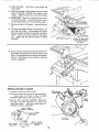
INSTALLING
BELT GUARD
1 Remove the belt and motor pulley
BELT GUARD
SUPPO
2 Screwsfurnished
with guard are"self threading"
o . . screw them into holes in BELT GUARD
SUPPORT BRACKET, then remove them.
PIVOT
SCREW
3, Position BELT GUARD SUPPORT BRACKET
and BELT GUARD SUPPORT as shown and
install the screws
. make sure motor shaft is in
CENTER of hole in SUPPORT
BELT
SUPPORT
GUARD
BRACKET
Two
Ho,.
c osEsT
s
TOGETHER
CENTERED
BELT
GUARD
SUPPORT
..,,,_-
_,,,,,_,,.
%
10-32 X 1t2 IN.
SELF-THREADING
SCREW
2O
OPENING
Install three CLIPS (furnished with guard) 90 °
apart starting with one clito at the end of the
guard as shown.,
LONG END of clip facing
AWAY from you
BELT GUARD
LONG END
5 Reinstall motor pulley the same way it was when
you aligned the belt
6, Place belt on SAW PULLEY ., insert end of belt
through opening in END of guard.
7 Slip belt over motor pulley
8, Press guard onto support so that bottom of
guard is approximately
3/4 in away from belt,
NOTE: To remove guard, lift up on LONG TABS
of clips
pull guard outward. The clips should
remain on the BELT GUARD SUPPORT
t
!
3/4 IN,
PLUGGING
IN MOTOR
1 From among the loose parts, find two wire ties,
2, Route motor cord along right side of cabinet and
snap ties in 1/4" hole in side of cabinet Secure
two cords in wire ties.
3 Plug motor cord into outlet on side of switch box,,
WIRE
EXTENSION
REMOVED
PICTURE
CLARITY
21
FOR
TIES
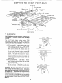
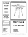
GETTBNG TO KNOW YOUR SAW
9
SAWBLADE
7
8
10
TABLE
BLADE
GUARD
INSERT
EXACT-I-CUT
ANTIK[CKBACK
PAWLS
6
MITER
GAUGE
5
RIP
FENCE
HOLES
ATTACHING
4
TILT LOCK HANDLE
(UNDERNEATH
TABLE)
/
2
ELEVATION
HANDWHEEL
3
\
I
1
ON-OFF
TILT
HANDWHEEL
SWITCH
ON-OFF SWITCH
CAUTION: Before turning switch on, make sure the
blade guard is correctly installed and operating
properly,
The On-Off Switch has a locking feature. THIS
FEATURE
IS INTENDED
TO HELP PREVENT
UNAUTHORIZED
AND POSSIBLE HAZARDOUS
USE BY CHILDREN AND OTHERS
@
A. TO turn saw ON ..... stand to either' side of the
blade never in line with it . , insert fingerunder switch lever and pull END of lever out
/ (YELLOW
After turning switch ON, always allow the
blade to come up to full speed before cutting
Do not cycle the motor +switch on and off
rapidly, as this may cause the sawblade to
loosen+ tn the event this should ever occur +,
atlow the sawblade to come to a complete
stop and retighten the arbor nut normally, not
excessively. Never leave the saw while the
power is "ON".
B. TO turn saw OFF .... PUSH lever in Never
leave the saw until the cutting tool has come
to a complete stop..
C.. TO lock switch in OFF position+., hold switch
IN with one hand..
REMOVE key with other
hand
WARNING:
For your own safety, lower blade or
other cutting tool below table surface. (If blade is
tilted, return it to vertical (90 o) position). Always lock
the switch "OFF". When saw is not in use...remove
key and keep it in a safe place.+.also...in the event of
a power failure (all of your lights go out) turn switch
off.+.lock it and remove the key. This will prevent the
saw from starting up again when the power comes
back on.
22
KEY
PLASTIC)
FOR
FACING
2
3
4
5
ELEVATION HANDWHEEL
....elevates or lowers
the blade.. Turn clockwise to elevate .... counterclockwise to lower
If necessary, the miter gauge head can then be
swiveled slightly to compensate and then locked..
TILT HANDWHEEL .... tilts the blade for bevel
cutting.. Turn clockwise to tilt toward left ......
counterclockwise
to tilt toward right.
Slots are provided in the miter gauge for attaching an AUXILIARY FACING to make it easier to
cut long pieces. Be positive facing does not
interfere with the proper operation of the sawblade guard
When the blade is tilted to the LEFT as far as it
will go, it should be at 45 ° to the table and the
bevel pointer should point 45 °
Select a suitable piece of smooth straight wood
..... drill two holes through it and attach it with
screws
NOTE: There are LIMIT STOPS inside the saw
which prevent the blade from tilting beyond 45 °
to the LEFT and 90 ° to the RIGHT° (See "Adjustments" section "Blade Tilt, or Squareness of
Blade to Table")..
NOTE: When bevel crosscutting,
attach facing
so that it extends to the right of the miter gauge
and use the miter gauge in the groove to the right
of the blade
TILT LOCK HANDLE..
locks the blade in the
desired tilt position
To loosen, turn counterclockwise. Push handle in and turn it to another
position
if necessary in order to tighten or
loosen
v
RIP FENCE
is locked in place by pushing the
lock lever down until the lever rests on the stop
To move the fence, lift the lock lever and grasp
the fence with one hand at the front.
STOP PIN
45 ° SLOT
FOR STOP PIN
7
Holes are provided in the rip fence for attaching
a wood facing when using the dado head, or
molding head.
Select a piece of smooth straight wood approx
3/4 in thick and the same size as the rip fence.
Attach it to the fence with three Round Head #10
Wood Screws 2 in tong. To remove the facing,
loosen the screws, slide the facing forward and
pul! the screws through the round holes
WOOD
t .........
Y
_
FAC|NG
i l
"_J_J
BLADEGUARD must always be in place and
working properly for all thru-sawing cuts That
is, all cuts whereby the blade cuts completely
through the workpiece
To remove the guard for special operations,
loosen the thumbscrew and slide the guard off of
othe rod. DO NOT DISTURB THE SETTING OF
THE ROD
When replacing the guard, make sure the PIN in
the rod engages with the NOTCH in the spreader
support. Make sure thumbscrew
is tightened
securely
FACING
1
8
TABLE INSERT is removable for removing
i_'stalling blades or other cutting tools
or
> )
\-..OU.D .EAo/
6
MITER GAUGE _. head is locked in position for
crosscutting
or mitering by tightening the lock
knob ALWAYS LOCK IT SECURELY WHEN IN
USE..
SCREW
WARNING:
"OFF" and
outlet before
A.. Lower
There are two slots for the stop pin at the 45
degree right and left positions for conveniently
setting the Miter Gauge to cut miters
NOTE: The slots for the stop pin and the graduations are manufactured to very close tolerances
which provide accuracy for average woodworkingo In some cases where extreme accuracy is
required, when making angle cuts, for example,
make a trial cut and then recheck it
For your own safety, turn switch
remove plug from power source
removing insert.
the blade below the table surface.
B. Raise blade guard
C Loosen Screw
D Lift insert from the front end, and pull toward
front of saw
23
NEVER OPERATE
THE SAW WITHOUT
THE
PROPER INSERT IN PLACE USE OF THE SAW
BLADE INSERT WHEN SAWING . . • USE THE
COMBINATION
DADO MOLDING INSERT WHEN
DADOING OR MOLDING..
9
REMOVING
AND INSTALLING
SAWBLADE,
WARNING:
For your own safety, turn switch
"OFF" and remove plug from power source
outlet before removing or installing sawbladeo
A Raise Blade Guard
NUT
remove insert.
WOOD
By To REMOVE blade, place a block of wood
against front of blade _. PULL arbor wrench
toward you to LOOSEN arbor nut
BLOCK
BLADE GUARD NOT SHOWN
FOR PICTURE CLARITY
BLADE GUARD NOT SHOWN
PICTURE CLARITY
C To TIGHTEN arbor nut, place a block of wood
against rear of blade .. PUSH wrench away
from you
When installing the blade .....make sure the teeth
are pointing toward the front of the saw .. and
that the blade and collars are clean, and free
from any burrs
The HOLLOW side of the collar must be against
the blade.
Always tighten the arbor nut securely
ARBOR
NUT
NOTE:When using the Dado or Molding Head, it
is not necessary to instat] the loose collar.
To replace insert.
Place insert into insert opening in table and push
towrd rear of saw to engage spring clip and until
keyslot in insert will drop over screw. Tighten
screw
Do not tighten screw to the point where it will
deflect the insert..
"10 EXACT-I-CUT
The "yellow" plastic disc imbedded in the table
in front of the sawblade, is provided for marking
the location of the "sawcut" on the workpiece_
A Check disc . . .. if it is above table surface,
place a piece of hardwood on top of it and tap
it down..
B,, With blade 90 ° (square to table) cut off a piece
of wood.
C. Pull miter gauge back until wood is over disc..
Using very sharp pencil, mark a line on disc..
BLADE GUARD NOT SHOWN
FOR PICTURE CLARITY
D With miter gauge in right hand groove, follow
same procedure and mark another line on
disc.
E These lines indicate the "path"
(kerf) made by the sawblade.
F. When cutting the workpiece,
workpiece with line on disc.
of the cut
line up mark on
24
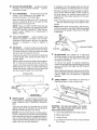
BASIC
WORK
SAW
OPERATION
HELPERS
Before cutting any wood on your saw, study all of the
"Basic Saw Operations"
SLIGHTLY LESS THAN
THICKNESS OF WORKPIECE
UP TO 3/8"
Notice that in order to make some of the cuts, it is
necessary to use certain devices "Work Helpers" like
the Push Stick, the Push Block and the Auxiliary
Fence/Work Support, which you can make yourself.
After you have made a few practice cuts, make up
these "helpers" before starting any projects Make
the "Push Stick" first
45 ° NOTCH
PUSH STICK AND PUSH BLOCK
NOTE: All dimensions
Make the Push S!ick using a piece of 1 x2, or rip one
from a wide board, say 11-1/2 in, wide, and set the rip
fence 9-7/8 in. from the sawblade.
in inches
PUSH STICK
THESE EDGES MUST
BE PARALLEL
Make the Push Block using a piece of 3/8 in and 3/4
in, plywood,
The small piece of wood 3/8 in x 3/8 in x 2-1/2 in
should be GLUED to the plywood.
DO NOT USE
NAILS, This is to prevent dulling the sawblade in the
event you mistakingly cut into the push block.
3/4 PLYWOOD
12
4-3/4
Position the handle in the center of the plywood and
fasten together with glue and woodscrews.
3/8
NOTE: All dimensions
in inches
PUSH BLOCK
25
3/8
3/8 PLYWOOD
3/4 PLYWOOD
AUXILIARY
FENCEP,
NORK
SUPPORT
3-1/2""
Make one using a piece of 3/8 in. and 3/4 in.. plywood
Fasten together with glue and wood screws.
1-1/4
NOTE: Since the Push Block is used with the Auxiliary
Fence, the 4-3/4 in. dimensions must be held identical
on both the pieces,
THIS FACE AND
EDGE MUST BE
PARALLEL
3/8 PLYWOOD
NOTE: All dimension in inches
AUXILIARY
FENCE/WORK
SUPPORT
3/4 PLYWOOD
AUXILIARY PANEL WORK SUPPORT
Make using a piece of 3/4" and 3/8" plywood. Fasten
together with glue and wood screws Use this auxiliary
panel work support only when cutting large panels that
require the rip fence to be positioned past the exposed
side of the extension.
3-5/8
[-3/8
FACE & EDGE
MUST BE
PARALLEL
3/8 PLYWOOD
NOTE: All dimension
2
in inches
AUXILIARY PANEL/WORK SUPPORT
SAFETY BNSTRUCTaONS
FOR BASIC SAW OPERATRONS
BEFORE EACH USE:
Make sure the spreader is in line with the
sawblade
REMOVE
ADJUSTING
KEYS
AND
WRENCHES
Form habit of checking for and
removing keys and adjusting wrenches from
tool before turning it on
1 inspect your saw
a. To avoid injury from accidental starting, unplug
the saw, turn the switch off and remove the
switch key before raising or removing the
guard, changing the cutting toot, changing
the setup or adjusting anything
b,, Check for alignment of moving parts, binding
of moving parts, breakage of parts, mounting,
and any other conditions that may affect the
way it works If any part is missing, bent, or
broken in any way, or any electrical parts don't
work properly, turn the saw off and unplug the
saw.
c
Reptace damaged, missing,
before using the saw again.
or failed
To avoid injury
pieces (kickback
from jams, slips
and throwback):
1. USE ONLY RECOMMENDED
or thrown
ACCESSO-
RIES (See page 42) _Follow the instructions
that come with the accessofie& Using other
accessories may be dangerou&
2. Choose the right blade or cutting accessory
for the material and the type of cutting you
plan to do,
3. Never' use grinding wheels, abrasive cut-off
wife wheels or buffing wheel. They can fly
apart explosively.
parts
d Use the sawblade guard, spreader, and antikickback pawls for any thru-sawing (whenever
the blade comes through the top of the workpiece). Make sure the pawls work properly
26
i
!'
Any power saw can throw foreign objects into
the eyes This can cause permanent
eye
damage Wear safety goggles (not glasses)
that comply with ANSi Z87,1 (shown on package) Everyday eyeglasses have only impact
resistant lenses, They are not safety glasses
Safety goggles are available at Sears retail
catalog stores Glasses or goggles not in
compliance with ANSI Z87..1 could seriously
hurt you when they break.
4 Choose and inspect your cutting tool carefully
a To avoid cutting tool,failure and thrown
shrapnel (broken pieces of blade), use
only 10" or smaller blades or other cutting
tools marked for speeds of 3450 rpm or
higher
b Always use unbroken, balanced blades
designed to fit this saw's 5/8" arbor
c,, When thru-sawing,
(making cuts where
the blade comes through the workpiece
top) always use a 10 inch diameter blade
This keeps the spreader in closest to the
blade,
d, Do not overtighten arbor nut. Use arbor
wrenches to "snug" it securely.
e Use only sharp blades with properly set
teeth
Consult
a professional
blade
sharpener when in doubt.
f Keep blades clean of gum and resin
WEAR
YOUR
- For dusty operatio6s, wear a dust mask along
with the safety goggles
3 inspect your workpiece
Make sure there are no
nails or foreign objects in the part of the workpiece to be cut,
4 Plan your cut to avoid KICKBACKS and THROWBACKS - when a part or alf of the workpiece
binds on the blade and is thrown violently back
toward the front of the saw:
5 Adjust table inserts flush with the table top
NEVER use the saw without the proper
insert
6 Make sure all clamps and locks are tight
and no parts have any excessive play
2. KEEP WORK AREA CLEAN
a Cluttered areas and benches invite accidents
Floor must not be slippery
from wax or
sawdust
- Never cut FREEHAND: Always use either a rip
fence, miter gauge or fixture to position and
guide the work, so it won't twist, bind on the
blade and kic,kback
-Make
sure there's no debris between the
workpiece and its supports
- When cutting irregularly shaped workpieces,
plan your work so it will not slip and pinch the
blade,,
b To avoid burns or other fire damage, never use
the saw near flammable liquids, vapors or
gases.
Plan ahead to protect your eyes, hands, face, ears.
a. To avoid injury from accidental blade contact,
don't do layout, assembly, or setup work on the
table while the blade is spinning It could cut or
throw anything hitting the blade
AVOID ACCIDENTAL STARTING - Make sure switch
is in "OFF" position before plugging saw in
Plan your work
1 USE THE RIGHT TOOL - Don't force tool or
attachment to do a job it was not designed for
2. Dress for safety:
Do not wear loose clothing, gloves, neckties
or jewelry (rings, wrist watches) They can get
caught and draw you into moving parts
° Wear nonstip footwear
- Tie back tong hair.
- Roll tong sleeves above the elbow.
- Noise levels vary widely To avoid possible
hearing damage, wear ear plugs or muffs
when using saw for long periods of time,
- A piece of molding, for example, must lie
flat or be held by a fixture or jig that will not
let it twist, rock or slip while being cut., Use
jigs, fixtures where needed to prevent workpiece shifting,
- Use a different, bettersuited type of tool for
work that can't be made stable
-Use extra caution with large, very small or
awkward workpieces:
-Use extra supports (tables, saw horses,
blocks, etc) for any workpieces
Iarge
enough to tip when not held down ot the
table top, NEVER use another person as a
substitute for a table extension, or as additional support for a workpiece that is longer
or wider then the basic saw table, or to help
feed, support or pull the workpiece
27
1 Before actually cutting with the saw, watch it
while it runs for a short while, If it makes an
unfamiliar
noise or vibrates excessively, stop
immediately
Turn the saw off. Unplug the saw
Do not restart until finding and correcting the
problem
2 Make sure the top of the arbor or cutting tool
turns toward the front of the saw.
- Never confine the piece being cut off That
is, the piece NOT against the fence, miter
gauge or fixture. Never hold it, clamp it,
touch it, or use length stops against it. It
must be free to move. If confined, it could
get wedged against the blade and cause a
kickback or throwback..
-Neve_
time..
cut more than one workpiece
at a
3 Set the cutting tool as tow as possible for othe cut
you're planning
4. KEEP CHILDREN AWAY All visitors should be
kept a safe distance from work Make sure
bystanders are clear of the saw and workpiece
5 Let the blade reach full speed before cutting
6 DON'T FORCE TOOL. it will do the job better
and safer at its designed rate. Feed the workpiece
into the blade only fast enough to let it cut
without bogging down or binding.
7 Before freeing any jammed material:
a Turn switch "OFF".
-Never
turn your table saw "ON" before
clearing everything except the workpiece
and related support devices off the table.
Plan the way you will push the workpiece through.
- NEVER pull the workpiece through Start and
finished the cut from the fron of the tabet saw
- NEVER put your fingers or hands in the path of
the sawblade or other cutting tool.
- NEVER reach in back of the cutting tool with
either hand to hold down or support the workpiece, remove wood scraps, or for any other
reason.
-Avoid awkward operations and hand positions
where a sudden slip could cause fingers or hand
to move into a sawblade or other cutting tool
- DON'T OVERREACH.
and balance.
b Unplug the saw.
c. Wait for all moving parts to stop.
d Check blade, spreader and fence for proper
alignment before starting, again
8. To avoid throwback of small, cut off pieces:
a Use the guard assembly
b.. To remove pieces trapped inside the guard:
t Turn saw off..
Always keep good footing
- Push the workpiece against the rotation of the
blade., NEVER feed material into the cutting tool
from the rear of the saw.
- Always push the workpiece
sawblade.
2 Remove switch key.
3. Unplug saw
4. Wait for blade to stop before
guard
all the way past the
- As much as possible, keep your face and body to
one side of the sawblade, out of line with a
possible kickback or throwback;
- NEVER turn the saw "ON" before clearing the
table of all tools, wood scraps, etc,, except the
workpiece and related feed or support devices
for the cut planned
lifting
the
BEFORE LEAVING THE SAW
1 Turn saw off
WHENEVER SAW IS RUNNING
WARNING:
Don't let familiarity
(gained from fre o
quent use of your table saw) cause a careless mistake. Always remember that a careless fraction of a
second is enough to cause a severe injury.
28
2. Wait for blade to stop spinning
3. Make workshop child-proof. Lock the shop, Disconnect master switches. Remove the yellow
switch key. Store it away from children and
others not qualified to use the tool.
4. Unplug the saw.
USING
THE
MITER
GAUGE
The MITER GAUGE is used when CROSSCUTTING,
MITER CUTTING, BEVEL CUTTING, COMPOUND
MITER CUTTING, DADOING andwhen RABBETTING
AND MOLDING across the end ol a narrow workpiece.
- An auxiliary wood facing attached to the miter
gauge can help prevent workpiece twisting and
throwbacks
Attach it to the holes provided
Make the facing long enough and big enough to
support your work Make sure, however, it will
not interfere with the sawblade guard
- Use jigs or fixtures to help hold any piece too
small to extend across the fulf length of the miter
gauge face during the cut This lets you properly
hoid the miter gauge and workpiece and helps
keep your hands away from the blade
WARNING: For you rown safety, always observe the
following safety precautions in additio n to the safety
instructions
on pages 2, 3, 4, 5, 6, 26, 27, and 28.
ADDITIONAL
FOR CROSS
SAFETY
INSTRUCTIONS
CUT TYPE CUTS
Before starting
- NEVER use the rip fence when crosscutting
While cutting
-To avoid blade contact, always hold the miter
gauge as shown in the BASIC SAW OPERATIONS - USING THE MITER GAUGE
WORKPIECE
CROSSCUTTING
1
Crosscut
A cutting or shaping operation made across the width
of the workpiece
The graduations
on the miter gauge provide
accuracy for average woodworking
In some cases
where extreme accuracy is required, when making
angle cuts, for example, make a trial cut and then
recheck it with an accurate square, or protractor
1 ill
TABLE
\
If necessary, the miter gauge head can be swiveled
slightly to compensate for any inaccuracy
NOTE: The space between the miter gauge bar and
the groove in the table is held to a minimum during
manufacturing
For maximum
accuracy when using the miter
gauge, always "favor" one side of the groove in the
table In other words, don't move the miter gauge
from side to side while cutting, but keep one side of
the bar riding against one side of the groove
NOTE: Glue a piece of sandpaper to the face of the
miter gauge head
This will help prevent the
workpiece from "creeping" while it is being cut
The Hold-Down
Clamp
(Optional
Accessory)
should be used on the miter gauge for greater
acc u racy
The miter gauge may be used in either of the
grooves in the table, Make sure it is locked
WARNING:
To avoid blade con;tact, hold the miter
AUXILIARY
FENCE/
WORK SUPPORT
gauge properly°
When using the miter gauge in the LEFT hand
groove, hold the workpiece firmly against the miter
gauge head with your left hand, and grip the lock
handle with your right
When using the RIGHT Hand groove, hold the
workpiece with your right hand and the iockhandfe
with your left hand
When cutting long workpieces, insert AUXILIARY
FENCE/WORK SUPPORT and position it on top of the
guide bars to support the workpiece as near to the end
as possible. If this does not adequately support the
workpiece, you can make a simple support by clamping
a piece of plywood to a sawhorse. See first illustration
under "Crosscutting".
Use a Hold-Down Clamp (Optional Accessory) on the
miter gauge for greater accuracy,,
29
REPETITIVE
\
CUTTING
REPETITIVE
CUTTING
is known as cutting
a
quantity of pieces the same length without having to
mark each piece,
t Use the Stop Rods (optional accessory) only for
cutting duplicate pieces 6 in, long and longer
2. Follow all safety precautions
instructions for cross cutting
and operational
When making repetitive cuts from a long workpiece,
make sure it is adequately supported
Use the Hold-Down Clamp (Optional
the miter gauge for greater-accuracy.
Accessory)
on
WORK
,RY FENCE/
SUPPORT
/
', ....
i i
\
i. NEVER USE THE RIP FENCE AS A LENGTH STOP
BECAUSE THE CUT OFF PIECE COULD BIND
BETWEEN THE FENCE AND THE BLADE CAUSING A KICKBACK
BLOCK
2 When making repetitive cuts shorter than 6 in., clamp
a block ol wood 2 in long to the table to act as a length
stop.. Do not clamp directly to the bottom edge of the
table because the swivel of the clamp will not grip
properly Place a small blcok of wood between the
bottom edge of the table and the "C" clamp.,
CAUTION: When clamping the block, make sure
that tile end of the block is well in front of the
sawblade. Be sure it is clamped securely.
4, Make th_ cut ......turn the saw oil .... remove the piece
3. Slide the workpiece along the miter gauge until it
touches the block .... hold it securely or' clamp it with
the Hold-Down Clamp (Optional Accessory)
MITER
after the blade has stopped and before cutting the
next piece
CUTTING
MITER CUTTING is known as cutting wood at an
angle other than 90 ° with the edge of the wood
Follow the same procedure as you would for crosscutting.
Adjust the miter gauge to the desired angle, and lock
it
The miter gauge may be used in either of the grooves
in the table.
When
groove,
gauge
handle
using the miter gauge in the LEFT hand
hold the workpiece firmly against the miter
he_id with your left hand, and grip the lock
with your right,
When using the RIGHT hand groove, hold the
workpiece with your right hand and the knob with
your' left hand
Use the Hold-Down Clamp (Optional Accessory)
the miter gauge for greater accuracy,
on
30
BEVEL
CROSSCUTTING
BEVEL CROSSCUTTfNG is the same as crosscutting
except that the wood is also cut at an angle
other
than 90 ° with the flat side of the wood
Adjust the blade to the desired angle.
Use the Miter Gauge in the groove to the RIGHT of
the blade It cannot be used in the groove to the
LEFT because the blade guard wilt interfere, Hold
the workpiece with your right hand and the lockhandle with your left hand
Use the AUXILIARY FENCE/WORK
additional support of the workpiece
SUPPORT
for
Lay it across the guide bars to support the workpiece
as near to the end as possible.
Use the Hold-Down Clamp (Optional Accessory)
the miter gauge for greater accuracy_
COMPOUND
MITER
on
CUTTING
COMPOUND MITER CUTTING is a combination of
miter cutting and bevel crosscutting,
The cut is
made at an angle other than 90 ° to both the edge and
the flat side of the wood,
Adjust the miter gauge and the blade to the desired
angle ,, Make sure miter gauge is locked
USUNG
THE
RIP FENCE
RIPPING, BEVEL RIPPING, PLOUGHING, MOLDING,
RESAWING AND RABBETTING are performed using
the RlP FENCE together with the AUXILIARY FENCE/
WORK SUPPORT, PUSH STICK OR PUSH BLOCK°
- A FEATHERBOARD
piece
24"
KERFS ABOUT
5/16" APART
WARNING: Make sure the featherboard against the
edge presses only on the uncut portion (forward of
the blade). It might otherwise pinchthe blade in the
kerf and cause a kickback.
ADDITIONAL
SAFETY
FOR RIP TYPE CUTS
4-1/2
5"
INSTRUCTIONS
Before starting
-To avoid kickbacks and slips into the blade,
make su re the rip fence is parallel to the sawblade
- Check the antikickback pawls (See BASIC SAW
OPERATION - USING THE RIP FENCE.) The
pawls must stop a kickback once it has started
Replace or sharpen antikickback
pawls when
points become dull
-Plastic
and composition
(like hardboard)
materials may be cut on your saw However,
since these are usually quite hard and slippery,
the aptikickback
pawls may not stop a kickback
Therefore, be especially careful in your set-up
and cutting procedures
- NEVER use the miter gauge when ripping
- Use a push stick whenever the fence is 2 to 6
inches from the blade, Use an auxiliary fence and
_push block whenever the fence must be within 2
inches of the blade.. (See "Basic Saw Operation
Using The Rip Fence" section..)
-When using a push stick or push block, the
trailing end of the board must be square A push
stick or block against an uneven end could slip
off or push the work away from the fence.
- Never rip anything
can help guide the work-
shorter than 10" long.
While cutting
-To avoid kickbacks and slips into the blade,
always push forward on the section of the workpiece between the saw blade and the rip fence
Never push forward on the piece being cut off
31
RiPPiNG
Ripping
A cutting operation along J.helength of the workpiece..
ALWAYS SUPPORT LONG WORKPIECES
Position the fence to the desired WIDTH OF RiP and
lock in place
Before starting
to rip, be sure
A Rip Fence is parallel to sawblade
B Spreader is properly aligned with sawblade
C Antikickback
pawls are functioning property=
When ripping LONG BOARDS or LARGE PANELS,
always use a work support
A simple one can be made by clamping
plywood to a sawhorse
BEVEL RIPPING NARROW
a piece of
WORK
When bevel ripping material 6 in.. or narrower, use
fence on the right side of the blade ONLY. This will
provide more space between the fence and the
sawblade for use of a push stick.. If the fence is
mounted to the left, the sawblade guard may interfere
with proper use of a push stick
USING FEATHERBOARDS
THRU-SAWING
FOR
/
Featherboards
are not employed for thru-sawing
operations when using the miter gauge.
Featherboards are used to keep the work in contact
with the fence and table as shown, and to help stop
kickbacks.
Add 7-1/2 inch high flat facing board to the fence,
the fult length of the fence
Mount featherboards to fence and table as shown,
so that leading edges of featherboards will support
workpiece
"C" CLAMPS
/
l'
FEATHERBOARD
WORK SUPPORT.
WARNING: Make sure the featherboard against the
edge presses only on the uncut portion (forward of
the blade). It might otherwise pinch the blade in the
kerf and cause a kickback.
Before starting the operation (switch "OFF" and
cutter below table surface):
(a) Install featherboards so they exert pressure on
the workpiece; be positive they are secure, and
(b) Make sure by trial that the featherboards
wilt
stop a kickback if one should occur.
32
CLAMPS
When "WIDTH OF RIP" is 6 in.. and WIDER use your
RIGHT Hand to feed the workpiece until it is clear of
the table.,
Use LEFT hand ONLY to guide the workpiece
not FEED the workpiece with the left hand.
.... do
When "WIDTH OF RIP" is 2 in, to 6 in. wide USE THE
PUSH STICK to feed the work.
When WIDTH OF RIP is NARROWER than 2 ir_,, the
push stick CANNOT be used because the guard will
interfere .... USE the AUXILIARY FENCE/WORK
SUPPORT and PUSH BLOCK.
Attach Auxiliary Fence/Work
with two "C" clamps.
Support
to rip fence
33
Feedthe workpieceby handalongthe AUXILIARY
FENCEuntil the endis approx.1 in,,pastthe front
edgeof the table,Continueto feedusingthe PUSH
BLOCK,
Holdtheworkpiecein positionandinstallthePUSH
BLOCK by sliding it on top of the AUXILIARY
FENCE/WORK
SUPPORT(ThisMayRaiseGuard)
BAFFLE
NarrowstripsthickerthantheAuxiliaryFence/Work
Supportmayenterthe guardandstrikethe baffle.
CAREFULLYraiseguard onlyenoughto clear'the
workpieceUsePUSHBLOCKto completecut
34
RESAWING
RESAWING is known as ripping a piece of wood
through its thickness.
Do not attempt to resaw
BOWED or WARPED material. NOTE: To RESAW a
piece of wood wider than 3-3/8 inch.
it will be
necessary to remove the blade guard ... and use the
AUXILIARY FENCE/WORK SUPPORT (See "Work
Helpers")
SMALL
BLOCK
OF WOOD
Clamp it to the table so that the workpiece wil! SLIDE
EASILY but not TILT or MOVE SIDEWAYS without
BINDING between the two fences.
/ /'\
Do not clamp directly to the bottom edge of the table
because the "swivel" of the clamp will not grip
properly.. Place a small block of wood between the
bottom edge of the table and the "C" clamp.
2. Make first pass to a depth slightly less than
one-half the widt h of the board; keep same face
of board against fence for second pass as the
first pass.
3, install blade guard immediately upon completion of the resawing operation.
WARNING: For your own safety:
1, Do not "back up" (reverse feed)
.....................
:
.....
...............
i ,,/,,i,
i,i,
AUXILIARY PANEL/
WORK SUPPORT
CUTTING
PANELS
When cutting p6nels (whenever fence is positioned
outside of table surface), ALWAYS use the AUXILIARY PANEL/WORK SUPPORT
I Unlock fence and raise rear end.
2 Position AUXILIARY FENCE/WORK SUPPORT
as shown and attach it with two "C" clamps
USING FEATHERBOARDS
NON-THRU
SAWING
FOR
Featherboards are not employed during non thrusawing operations when using the miter gauge
Use featherboards for all other non "thru-sawtng"
operations
(when
sawMade
guard
must be
removed) Featherboards are used to keep the work
in contact with the fence and table as shown, and to
stop kickbacks
Add 7-1/2 inch high flat facing board to the fence,
the fult length of the fence.
Mount featherboards tO fence and table as shown,
so that leading edges of featherboards will support
workpiece until cut is complete, and the workpiece
"C '° CLAMPS
/
has been pushed completely
(sawblade, dado head, molding
pushstick, as in ripping
Before starting the operation
cutter below table surface):
past the
head, etc)
(switch
cutter
with a
"OFF"
and
(a) Install featherboards so they exert pressure on
the workpiece; be positive they are secure, and
(b) Make sure by trial that the featherboards
stop a kickback if one should occur
wilt
Replace the sawblade guard as soon as the non
thru-sawing operation is complete
)ARD
CLAMPS
WORK SUPPOR'F.
"C" CLAMPS
35
RABBETING
RABBETING is known as cutting out a section of the
corner of a piece of material, across an end or along
an edge,
_- FIRST CUT
RABBET
I SECOND
j
CUT
To make a RABBET requires cuts which do not go al!
the way through the material Therefore the blade
guard must be removed
1 Remove blade guard.
2 For rabbeting along an edge (long way of workpiece) as shown, add facing to rip fence approximately as high as the workpiece is wide. Adjust
rip fence and blade to required dimensions; then
make first cut with board flat on table as any rip
(type) cut; make second cut with workpiece on
edge. Follow afl precautions, safety instructions,
and operational instructions as for ripping, or rip
type operations, including feather boards and
push stick, etc.
RABBETING ALONG
THE EDGE
3 For rabbeting across an end, for workpiece 101/2" and narrower make the rabbet cut with the
board flat on the table. Using the miter gauge
fitted with a facing, follow the same procedures
and instructions for cross cutting making successive cuts across the width of the workpiece to
obtain the desired width of cut. DO NOT use the
rip fence for rabbeting across the end
4, INSTALL BLADE GUARD IMMEDIATELY UPON
COMPLETION OF RABBETING OPERATION,
PLOUGHING
RABBETING
ACROSS THE END
Rabbet cuts can also be made in one pass of the
workpiece over the cutter using the dado head or
molding head
AND MOLDING
MOLDING is shaping the workpiece with the grain
the long way of the workpiece, using the fence Use
featherboards and push sticks as required
PLOUGHING is grooving with the grain the long
way of the workpiece, using the fence USE featherboards and push sticks as required
PLOUGHING
MOLDING
LJ
DADOING
Instructions
for operating the Dado Head are contained in booklet furnished with the Dado Head.
The Recommended
Dado Head is listed
Recommended Accessories in this manual
®
under
The arbor on the saw, is only long enough so that the
widest cut that can be made is t3/!6" wide.
It is not necessary to install the outside loose collar
before screwing on the arbor nut.. Make sure the
arbor nut is tight.
ALWAYS USE DADO INSERT LISTED
RECOMMENDED
ACCESSORI ES.
LOOSE COLL
tff
UNDER
When using the dado head, it will be necessary to
remove the Blade Guard and Spreader. Use MITER
GAUGE, FENCE, FEATHERBOARDS,
and PUSH
STICK, etc. as required.,
ARBOR NUT1"
REMOVE
ALWAYS REPLACE THE BLADE, GUARD AND
SPREADER WHEN YOU ARE FINISHED DADOING.
.......
_,
I "_,, SAW ARBOF
SAWBLADE
INSTALL
DADO HEAD
BACK OF SAW
36
AND I
[
MOLDING
CUTTING
Instructions tor operating the Molding Head are contained in a booklet furnished with the Molding Head.
When using the molding head, it will be necessary to
remove the Blade Guard and Spreader
USE CA[JTION.
USE MITER GAUGE, FENCE, FEATHERBOARDS, AND PUSH STICK, ETC., AS REQUIRED.
The recommended molding head is listed under Recommended Accessories in this manual_
Always use Molding
mended Accessories.
Insert listed
under
ALWAYS REPLACE THE BLADE GUARD AND
SPREADER WHEN YOU ARE FINISHED MOLDING
Recom-
ADJUSTMENTS
LOCK
WARNING: For your own safety, turn switch "OFF"
and remove plug from power source outlet before
making any adjustments,
MITER
KNOB
BAR
GAUGE
NOTE: The slots for the stop pin and the graduations
are manufactured
to very close tolerances which
provide accuracy for average woodworking.
In some
cases where extreme accuracy is required, when
making angle cuts, for example, make atrial cut and
then recheck it
SQUARE
INDICATOR
BLOCK
if necessary, the miter gauge head can be swiveled
slightly to compensate for any inaccuracy.
1.. Loosen the "knob"
and pull "stop pin" OUT.
2. Swivel the head
position it at "0".
stop pin IN. . lock the handle..
push the
3.. The HEAD should be square with the Bar and the
pointer should point to "0".. Readjust the pointer
if necessary
t
4 If the head is not square with the bar, adjustments
are required
A Loosen the "knob"
(2).
(1) and the "two screws"
B. Position the HEAD square with the BAR using
a combination square
C PUSH the STOP PIN into theslot in the head at
"0 ...... push the pin into the slot and twist it
Lock the knob.
D. Recheck with the square, lfthe head is still not
square, loosen the screws (2) and readjust the
INDICATOR BLOCK.
i/8
E With the head square with the bar and the pin
pushed into the slot adjust the pointer (3) to
point to "0".
IN. SETSCREW
WRENCH
NOTE: The setscrew isiocated
inside of the
head, To reach it, swivel the head to 60
degrees and turn the miter gauge upside
down,
F The miter gauge head must rest on top of the
bar without being able to move up and down
... yet it must swivel freely.
G The swiveling movement of the head can be
adjusted by tightening or loosening the setscrew (4).., using the 118 in. setscrew wrench
37
HEELING ADJUSTMENT
PARALLELISM
OF SAWBLADE
GAUGE GROOVE
or
TO NtlTER
While cutting, the material must move in a straight
line PARALLEL to the SAWBLADE .... therefore both
the miter gauge GROOVE and the RIP FENCE must
be PARALLEL to the SAWBLADE..
If the sawbtade IS NOT parallel to the miter gauge
groove, the blade will bind at one end of the cut
(This is known as "HEELING").
To check for parallelism:
WARNING: For your own safety, turn switch "OFF"
and remove plug from power source outlet.
/
1 Raise blade all the way up
raise b{ade guard
2.. Mark an "x" on one of the teeth which is SET
(bent) to the LEFT
3. Place the head of a combination
square in the
GROOVE .... adjust blade of square so that it just
touches the tip of the MARKED tooth
5. if tooth touches square at FRONT and REAR...
sawblade
is PARALLEL
to MITER GAUGE
GROOVE.
4. Move square to REAR, rotate blade to see if
MARKED tooth again touches blade of square.
6 ff tooth does not touch the same amount
.. the
mechanism
underneath
must be adjusted to
make the blade PARALLEL to GROOVE
A Rear trunnion must be moved TOWARD the
combination square if there is a space between
marked tooth and end of square in step 4
B.. Rear trunnion must be moved AWAY from the
square if marked tooth pushes square out of
position in the groove.
REAR-TRUNNION
SCREWS
7 Loosen all three screws that hold the rear trunnion
and all three screws that hold the front trunnion
NOTE: All six screws can be reached through
back of saw. Use a 9/16 in., wrench To reach
left-hand front trunnion screw, tilt blade to 45°..
After loosening screws reposition blade at 90 °,_
/
J
FRONT-TRUNNION
38
\
SCREWS
EDGE OF TRUNNION
8 Using a wood block and mallet as shown, move
rear trunnion to right or left as required to realign
the blade.. If necessary, shift front trunnion in
similar manner; but do NOT move front trunnion
unless necessary Recheck the alignment with
the square, then securely retighten all six trunnion
screws
WOOD
PLACE
BLOCK
BLOCK
HERE
-- OR HERE
REAR
OFSAW
EDGE OF
CRADLE
BLADE TILT, OR SQUARENESS
OF BLADE TO TABLE
90 ° (SQUARE) and 45 ° (BEVEL) STOP COLLARS..
When the bevel pointer is pointing directly to the "0"
mark on the bevel scale, the sawblade should make a
SQUARE cut 90 ° to the table
To check for SQUARENESS:
WARNING: For your own safety, turn switch "OFF"
and remove plug from power source outlet°
1 Raise blade all the way UP.
raise blade guard..
2 TILTbladeafewdegreestotheLEFT
. now tilt
blade back to the RIGHT as far as it will go
3 Place the square against blade. Make sure square
is not touching the TI P of one of the saw TEETH
,,
4. Operate
the tilt-lock
handle
(COUNTERCLOCKWISE) to loosen the tilt clamp screw..
_
5, NOTE: Handle is spring loaded for engagement
with screw head - must be pushed inward for
disengagement whenever necessary to obtain a
new grip on screw head..
I=
.i
°
___o
m
_TILTCLAMPSCREW
_._._
LOCK
HANDLE
6 Rotate tilt handwheel CLOCKWISE a few turns
to tilt
blade
Now
rotate
handwheel
COUNTERCLOCKWISE
until it stops. Blade
should now be square with table and pointer
should point to "0".
TILT
BEVEL SCALE
39
HANDWHEEL
/
TILT
POINTER
If blade is SQUARE to table;
POINTER
A. Check pointer
tF POINTER DOES NOT point to the"0"
bevel scale;
mark on the
\
A Remove Elevation Handwheel,
SCALE ADJUSTING
B Loosen screw and adjust pointer
medium screwdriver,
-y
. _ , using
SCREW
/
POINTER AT
"0" POSITION
C Install Elevation Handwheel
if blade is NOT SQUARE to table ..... the 90 ° LIMIT
STOP must be ADJUSTED,
1.. Using a medium size screwdriver,
setscrews in 90 ° STOP COLLAR.
loosen BOTH
NOTE: If you can't reach the setscrews,
TILT HANDWHEEL slightty_
turn the
45 _ STOP COLLAR
2, ROTATE the STOP COLLAR moving it all the
way to the end of TILT SCREW (to the right)._
3. TILT blade RIGHT or' LEFT .... checking
your square until blade is square to table.
with
90 ° STOP COLLAR
4., ROTATE STOP COLLAR moving it to the right
until it stops _.. TIGHTEN the setscrew&
TILT
HANDWHEEL
5,_Check POINTER If it DOES NOT point to the"0"
mark on the bevel scale ._.
A Remove Elevation
REAR OF SAW
/
HandwheeL
B, Loosen screw and adjust
medium screwdriver,
pointer .....
using
C Install Elevation Handwheet,
45 ° POSITION
TILT blade to LEFT as far as it will go, It will stop
when the PIVOT NUT is against the 45 ° STOP
COLLAR
Ao Place an ACCURATE square against blade.
Make sure square is not touching the TIP of
one of the saw TEETH,
If blade is 45 ° to table;
A_ Check pointer.
If POINTER DOES NOT point to the 45 ° mark on the
scale;
A Remove Elevation Handwheel,
B,, Loosen two screws on scale and adjust scale
until POINTER points to 45 ° mark_
C, Install Elevation Handwheel,
4O
If bladeisNOT45° STOPCOLLARandSCALEmust
beADJUSTED,.
I, RemoveElevationHandwheel.
2. Usingasmallsizescrewdriver,reachthrucurved
slot in front trim paneland loosenBOTHsetscrewsin 45° STOPCOLLAR.
NOTE:If youcan'treachthesetscrews,turn the
TILT HANDWHEEL
slightly.,
3, ROTATEthe STOPCOLLARmoving it IN or
OUT and TILT blade RIGHT or LEFT ....
checkingwith your squareuntil blade is 45 _ to
table.
4, TIGHTEN
the setscrews,
NOTE: If you can't reach the setscrews,
TILT HANDWHEEL slightly.,
turn
5,, Loosen two screws on scale and adjust scale
until POINTER points to 45 ° mark,
6,, Install Elevation
Handwheel
TILT MECHANISM
The handwheel should turn freely without binding
The turning action can be adjusted by tightening or
loosening the screws in the bearing retainer
TILT HANDWHEEL
NOTE: Tilt Handwheel must be removed to adjust,
When adjusting the screws in the bearing retainer,
hold the nut inside using a 3/8 in wrench.
ADJUST
_
TWO
THESE
SCREWS
MAINTENANCE
\
WARNING: For yourown safety, turn switch "OFF"
and remove pJug form power source out_et before
maintaining or lubricating your saw.
Do not allow sawdust to accumulate
inside the saw,
Frequently blow out any dust that may accumulate
inside the saw cabinet and the motor.,
Frequently clean your cutting tools with Craftsman
Gum and Pitch Remover..
A coat of automobile-type
wax applied to the table
will help to keep the surface clean and allow workpieces to slide more freely,,
2. Rotate pawl toward rear of spreader so that teeth
are above top of spreader,,
If the power cord is worn or cut, or damaged in any
way, have it replaced immediately,
Make sure the teeth of the ANTIKICKBACK
are always sharp,. To sharpen:
3. Hold spreader with left hand and place pawl over
corner of workbench,
pawls
4 Using a small round file (Smooth Cut) sharpen
the teeth
1, Remove blade guard
41
LUBRUCATgON
The following
parts should be oiled occasionally
with SAE No, 20 or No 30 engine oil
t. Titt screw threads and pivot nuL (First Clean with
Craftsman Gum & Pitch Rernover..)
2 Elevation screw threads and pivot nut (First
Clean with Craftsman Gum & Pitch Remover.)
3. Cradle bearing points..
4. Bearing points in guard assembly,
and rip fence.
miter gauge
0
BEARING
POINTS
llllm,_,1/ i
SEARS RECOMMENDS THE FOLLOWING ACCESSORUES
ITEM
CAT, NO.
Caster Set ........................................................................
9-22221
Caster Set ..............................................................................
9-22222
ITEM
CAT. NO,
Work Light .....................................................................
See Catalog
7 In,,Dia, Adjustable Dado Head ................See Catalog
7 In, Dia Dado Head ...................................See Catalog
Sanding Wheel .................................................................
See Catalog
Miter-Gauge Stop Rods ...................................................
9-29924
Miter-Gauge Hold-Down Clamp .........................9-29928
Taper Jig .............................................................
See Catalog
Universal Jig ..................................................................
See Catalog
Power Tool Know How Handbook .....................9-29117
7 In. Molding Head Set .......................................
See Catalog
7 In.. Molding Head .....................................................
See Catalog
8 in,. Dado ...................................................................
See Catalog
Molding/Dado insert for 7 In,. Dia,
Molding or Dado Head ..........................................
9-29997
MoldinglDado Insert for 8 in. Dia,
Molding or Dado Head .................................................
9-22287
Sears may recommend other accessories not listed in the manual. See your nearest Sears store or Catalog
department for other accessories. Do not use any accessory unless you have received and read complete
instructions for its use.
42
TROUBLE
SHOOTUNG
WARNING: For your own safety, turn switch "OFF" and always remove plug from
power source outlet before trouble shooting.
TROUBLE
TROUBLE
PROBABLE
-- GENERAL
CAUSE
REMEDY
vibration.
1. Blade
out of balance,
I. Discard
make square
1. Miter
gauge not adjusted
I, See "Adjustments"
Excessive
Cannot
SHOOTING
Cut when crosscutting,
Cut binds, burns
stalls motor
or
when
and use a different
section
blade_,
"Miter
Gauge/°
properly.
I, Sharpen
1, Dul] blade with improper
tooth
ripping°
Blade
or"iep'i'ace"'l_'iade,
.....
set°
2, Blade
2. See "Adjustments"
is Heeling.
3 Warped
section,
3. Make sure concave
board
"down,"
4o Rip fence not parallel
"Heeling
or hollow
Adjustment
side is facing
feed slowly
4. See °'Assembly"
section,
"Aligning
Rip Fence"
5, See "Assembly"
Blade Guard."
section, "Installing
to blade,•
5. Spreader
.............
alignme,nt
Cut not true at 90 °
1, Stop
adjusted,
Tilt and elevating
1. Sawdust
turn hard°
of
, ,
collars
or 45 ° positions,
handwheel
out
1, See ""Adjustments"
not properly
section, "B'lade Tilt,'0r
"Squareness of Blade to Table."
on threads
screw or elevating
2, Bearing
of tilt
1. See "Maintenance
and Lubrication"
section,
screw_
2. See "Maintenance"
retainers
"Tilt
to tight,,
TROUBLE
SHOOTING
section
and Elevation
Mechanisms"
-- MOTOR
NOTE: Motors used on wood-working tools are particularly
susceptible to the accumulation of sawdust and wood chips
and shouid be blown out or "vacuumed"
frequently
to
prevent interference with normal motor ventilation,
PROBABLE
TROUBLE
Excessive
noise°
CAUSE
REMEDY
1. Motor,
1. Have motor
technician
your
Motor
1_ Circuit
fails to develop
overloaded
full power., (Power
lights,
appliances
output
of motor
other
motors,,
rapidly
with
volta_]e
at motor
decreases
decrease
For example,
a reduction
maximum
of which
a reduction
of 19% in
power output
capable, while
2, Undersize
too
wires
or circuit
2_ Increase
at
or motors
on
using the saw,
is
a reduction
3, General
power
overloading
3, Request
of
length
of wiring.
and Electrical
section°
a voltage
check
from
the power
company
facilities,
sections
country,
electrical
power output,)
Specification
Requirements"
a reduction
of 36% in
wire sizes, or reduce
See "Motor
long,
of 20% in voltage causes
maximum
appliances
same circuit when
and
service
is available
Sears store.
1, Do not use other
with
causes
the motor
nearest
by qualified
service
in
terminals,
of 10% in voltage
checked
Repair
exceed
(In some
of the
demand
power
for
may
the capacity
of existing
generating
and distribution
4., Incorrect
breakers
systems)
fuses or circuit
in power
4. Install
line.
43
correct
fuses or circuit
breakers
company,
.... "
TROUBLE
TROUBLE
SHOOTING
PROBABLE
or fails to come up
to full
Motor
REMEDY
,,
...............
1 Low voltage
2. Windings burned out
or open
3,, Starting switch not
operating
starts s|owly
speed.
overheats°
1. Motor
cooling.
circu lation
through
3. Have switch rep/aced
sawdust,
'
(Air
"1,, 'Feed work
2, Clean
restricted
motor
,,,, ,,,
1. Request voltage check from powe_company
2,, Have motor repaired or replaced
over!oaded,_
2; Improper
(Continued)
CAUSE
.............
Motor
-- MOTOR
circulation
due to
slower
out sawdust
into blade,
to provide
through
See "Maintenance
normal
air
motor,.
and Lubrication"
section.
accumulating
inside of saw).
1., Burned
Starting switch in
motor will not
switch
contacts
t. Have switch
(due to extended
operate.
hold-in
from
periods
and request
a voltage
check
company.
caused
by low fine voltage,
2, Shorted
replaced
the power
etc..)
capacitor
2. Test capacitor and replace if defective,,
(when equipped}
3_ Loose or broken
3. Have wiring checked and repaired,
connections.
....
Motor
stalls
(resulting
in blown
fuses or tripped
circuit
breakers)_
j
........................
1o Starting
switch
not
1,, Have switch
replaced_
operating.
2, Voltage
motor
too
tow to permit
2. Request
voltage
check
from
the power
company,,
to reach operating
speed_
3o Fuses or circuit
breakers
3_ Install
proper
size fuses or circuit
breakers,,
do not have sufficient
capacity.
...................
Frequent opening of
fuses or circuit
breakers.
,1o Motor'
=
overloaded,.
2_ Fuses or circuit
...............
1. Feed work
breakers
2, Install
slower
proper
into blade,.
size fuses or' circuit
do not have sufficient
capacity,.
3. Starting
operating
switch
not
(motor
3, Have switch
does
not reach speed)°
44
replaced.
breakers
FIGURE
Key
No.
Part
No,
1
2
3
4
62942
62945
62775
9404336
5
6
7
8
62941
423567
62946
STD600805
9
62528
1 - RIP FENCE
ASSEMBLY
Key
No.
Description
Handle
Shoe
indicator
Screw, Pan Cross Type "T"
No, 4-40 x 1/4
Head, Fence
Screw Sems 3/8-16 x 1/2
Channel, Fence
Screw Pan Cross Type 'q-"
8-32 x 1/2
Spring, Fence Lock
.............
62952
Part
No.
Description
10
11
12
13
62529
62531
62944
62533
14
t5
STD551210
STD611005
16
17
18
62532
62940
62943
Lock, Rear Fence
Roller, Rear Fence
Rod, Fence Lock
Spring, Head Alignment
(Includes Key #16)
Lockwasher, External No,. 10
Screw, Hex Head Type "A"
No 10 x I/2
Pad, Alignment
Cam
Nut, Adjustment
* Standard
Hardwa[e
ttem-- May be purchased locally,
, ,,,lUl
ilUU
ii u ll
.ll.
i
t
S
l
6
I
FIGURE
Key
Noo
.........
_"
1
2
3
4
5
6
2 - ON/OFF
POWER
Part
No,
OUTLET
60381
Description
i/n ul ul
U,Ull ,i
60381
...... • On/Off Power Outlet Complete
60375
Cord, Molded
60380
Housing, Switch
9-22255
t- Key, Switch
60374
Switch, Locking
60377
Cover, Switch
448007
Screw, Pan Hd,, No 6 x 3/4
f
Does Not Include Key No. 3 Order Separately
If Required
45
Stock 1tern - May be secured through the hardware
department of most Sears Retail Stores or Catalog
Order Houses,
PARTS
LIST FOR CRAFTSMAN
10 INCH TABLE SAW
MODEL NO. 113.298760
12
7
8
9
10
13
16
t4
6
5
8
O_
34
32
33
31
Figure3
35
7
PARTS
LIST FOR CRAFTSMAN
10 INCH TABLE SAW
MODEL NO. 113,298760
Always
order
by Part Number
FIGURE
Key
No.
11
12
13
14
15
16
17
18
62718
STD501102
133645
162584
62493
i62952
62710
62709
19
20
21
22
23
62539
60381
STD523117
9-29929
STD511107
3 PARTS
LIST
No.
Part
NO.
Description
lullul,lll
62579
STD522506
STD55t225
STD541025
ST D523110
62541
STD55123t
STD54103!
60313
62703
not by Key Number.
Key
Part
No.
1
2
3
4
5
6
7
8
9
t0
-
ii
hi,J/u/u,,,,,,
24
25
26
27
28
29
30
31
32
33
34
35
36
37
38
39
40
41
42
Guard Assembly
(See Fig. 6)
*Screw, Hex Hd. 1/4-20 x 5/8
*Lockwasher,
External t/4
*Nut,
Hex 1/4-20
*Screw,
Hex 5/16-18 x 1
Bar, Fence Rear
*Lockwasher,
External 5/16
*Nut,
Hex 5/16-18
Nut, Self-threading
insert Assembly,
(includes
Key No. 11 & 12)
Clip, Retaining
*Screw, Locking Set 10-32 )f 3/16
Screw, Fiat Hd. 10-32 x 1
Rod, Separation
insert, Exact-l-Cut
Fence Assembly,
Rip,See
Fig. I)
Tape, Fence
Bar Assembly, Fence Guide
(includes
Key No. I7)
Spacer, Fence Guide Bar
Switch Assembly
Box (See Fig. 2)
*Screw, Hex 5/16-I8
x I-3/4
I Gauge Assembly,
Miter (See Fig. 5)
"Screw, Pan Hd. t0-32 x 3/4
* Standard Hardware !tern - May be purchased locally.
NOTE: Shipping and handling charges for standard hardware items
(identified by *1 such as nuts, screws, washers, etc., make
buying these items by mail uneconomical. To avoid shipping
and handling charges, you may obtain most of these locally.
i
STD551210
818526
STD511103
820070
STD610805
62702
62700
60252
60255
STD601!05
60253
60254
454896
STD551237
71165
STD54141t
820030
STD522507
STD551031
62750
62751
SP5415
Description
Hi u uiH,l,/u/llt
ii
............
*Lockwasher,
External No. 10
Handwheet
Assembly
*Screw, Pan Hd. t0-32 x 3/8
Panel, Front
*Screw, Pan Hd. Ty "AB" No. 8 x 1/2
Scale, Adiustable
Bevel
Base
Guard, Bett
Ciip, "S"
*Screw, Pan Hd. Ty "T" 10-32 x !/2
Support, Belt Guard
Bracket, Support
*Screw, Hex Hd. 3/8-16 x 1/2
*Lockwasher,
External 3/8
Tie, Wire
Nut,, Lock 10-32
" Motor
*Screw, Hex Hd. 5/16-18 x 3/4
"Washer, 21/64 x 5/8 x 1/16
Bag of Loose Parts (Not illustrated)
(Includes Bag 62751)
Bag of Loose Parts (Not iilustrated)
Owners Manual (Not Hfustrated)
* Any attempt to repair this motor may create a hazard unless repair
is done by a qualified service technician. Repair service is available
at your nearest Sears Store.
t
Stock Item - May be secured through the hardware department of
most Sears Retail Stores or Catalog Order Houses,
PARTS
1
3
4
5
6
LIST FOR CRAFTSMAN
10 INCH TABLE
MODEL NO. 113.298760
SAW
7
f
12
/
14
19
20
21
16
15
6t
!8
1
60
59
,p,
Go
25
22
23
31
49
23
t
42
®
45
f
28
39
31
32
44
29
32
38
37
36
35
34
34
33
Figure
4
32
30
PARTS
LIST FOR CRAFTSMAN
10 INCH TABLE
MODEL NO. 11&298760
FIGURE
Part
No.
NO.
i
4_
,,O
1
2
3
4
5
6
7
8
9
10
tl
12
13
I4
15
16
t7
18
19
20
21
22
23
24
25
26
27
28
29
30
31
32
*
62587
60204
STD571812
STD523106
STD523110
STD551231
62292
STD541031
STD532507
60206
60205
STD551037
63011
62295
62833
62696
9-32138
62498
6362
3540
62437
62698
37900
STD523710
STD551237
37899
63054
37828
18
37829
STD581062
37838
4 PARTS
Descr!ption
........................
Support, Spreader
Screw, Thumb 5/16-18 x 1
* Pin, Roll 3/16 x 1-1/4
* Screw Hex Hd. 5/16-18 x 5/8
* Screw, Hex Hd. 5/16-18 x 1
* Lockwasher, External 5/16
Support, Guard
* Nut, Hex 5/16-18
* Bolt, Carriage 5/16-18 x 3/4
* Screw, Hex ind. Wash. Hd. 1/4-10 x 1-1/2
Spring
* Washer, .380 x 47/64 x 3/32
Washer, Knob Clamp
Spacer
Table, Trunnion
Table, 10 In. Saw
t- Blade, Saw 10 ln.
Collar, Blade
Nut, Arbor
Wrench, Arbor
Retainer, Bearing
Screw, Tilt
Collar, Stop
* Screw, Hex Hd. 3/8-16 x 1
* Lockwasher, External 3/8
Nut, Tilt
Ring, Retaining 3/4
Spring, Clamp Screw
Handle, Clamp Screw
Screw, Clamp
* Ring, Retaining 5/8
Washer, .629 x 7/8 x 1/64
Standard Hardware Item - May Be Purchase Locally.
SAW
LIST
Key
No.
Part
No.
Description
ii
33
34
35
36
37
38
39
4O
41
42
43
60i'78
STD302111
62697
62699
STD601103
STD551210
62489
62312
6527
STD304410
30419
44
45
46
47
48
49
50
51
52
53
54
55
56
57
58
59
60
61
62
STD328022
STD600803
3508
37158
3509
30420
STD580025
6532
37825
37824
37823
STD581037
37836
37887
37837
30628
6423
STD551025
62585
li, lll,ll
u nHl,ullll
Washer, Spring
O-ring
Screw, Lift
Pointer
Screw Pan Hd. Ty "T" 10-32 x 3/8
Lockwasher, External No. 10
Cradle (Includes Key No's. 40 and 41)
Link
Ring, Retaining 3/4
Belt, V 1/2 x 41
Housing, Arbor Assembly (includes Key No's.
44, 45, 46, 47, 48, 49, 50, and 51)
Pulley, 5/8 Bore (Includes Set Screw)
Screw, Pan Hd. Ty "T" 8-32 x 3/8
Retainer, Arbor Bearing
Ring, Retaining 5/8
Bearing, Saw Arbor
Housing, Arbor
Key, Woodruff
Arbor (Includes Key No's. 31,47, and 50)
Sup'port, Motor Base
Base, Motor
Pin, Hinge
Ring, Retaining 3/8
Wrench, Hex "L" 3/32
Wrench, Hex "L" 1/8
Wrench, Hex '%" 5/32
Screw, Pivot Arm
Washer, Spring
Washer, 17/64 x 47/64 x 1/16
Rod, Spreader
Stock Item - May be secured through the Hardware Department
of most Sears Retail Stores or Catalog Order Houses.
PARTS
LIST FOR CRAFTSMAN
10 INCH TABLE
MODEL NO. 113.298760
1
2
SAW
4
3
I
/
12
/
/
11 1
14
6
6
7
10
8
10
9
9
FIGURE
Key
No.
t
2
3
4
5
6
9
10
11
12
13
14
5 - MITER
GAUGE
ASSEMBLY
FIGURE
Part
No.
Key
No.
Description
9-29929
62693
62692
+Gauge Assembly, Miter
Plug, Button
Knob, Miter Gauge
(Includes Key Nov 1)
STD 551031 *Washer, Plain, 21/64 x 1 x 1/16
37893
Gauge, Miter
STD 510803 1*Screw, Pan Hdo 8_32 x 5/16
135
Indicator
37895
Block, Miter Gauge Indicator
37896
Pin, Miter Gauge Stop
9417295
*Screw, Pan Hd,,,
w/Lockwasher, 8-32 x 5/8
62230
Rod Assembly, Miter Gauge,
Consisting of Items 11, 12, 13
STD 541231 *Nut, Hex. 5/16-18
62225
Stud, Clamp
62383
Stud, Pivot
60288
Screw, Locking Set 1/4-20 x 3/8
* Standard
Hardware
Item
!
2
3
4
5
6
7
8
9
10
11
12
- May Be Purchased
+ Stock Item - May be secured through
of most Sears Retail Stores or Catalog
5O
6 - 62579 GUARD
Part
No.
62579
60297
62391
62395
,62389
62390
STD 551025
62520
62396
62580
62410
STD 571810
62519
Locally.
the Hardware
Department
Order Houses,.
ASSEMBLY
Description
Guard Assembly, Saw
Nut, Push
Pin 1/4 x 1-1/2"
Support, Guard
Guard, Saw
Pin, 1/4 x 1-3/4"
*Washer, 17/64 x 5/8 x 1/16"
Spacer, Pawl
Pawl
Spreader, Assembly Blade
Pin, 1/4 x 1"
*Pin. Roll, 3/t6 x t5/16"
Spring, Pawl
PARTS
3
1
4
LIST FOR CRAFTSMAN
10 INCH TABLE
MODEL NO. 113.298760
SAW
5
10
6
2
5
4
L
3
FIGURE
Key
No.
Part
Noo
FIGURE
7 - LEGS
Key
No.
9
STD 523! !2!*Screw,
Part
No.
Description
!
60314
Screw, Serrated Truss Hd 1/4-20
2
62552
Leg
3
62554
Stiffener,
Side
4
STD 551225 *bockwasher,"Ext 1/4
5
STD 541025 *Nut, Hex 1/4-20
6
62553
Stiffener,
End
7
STD 541250 *Nut, Hex 1/2-13
8
803835
Foot, Leveling
HARDWARE FOR ATTACHING
LEGS TO SAW.
10
11
12
8 - TABLE
x 5/8
1
2
62947
STD523112
3
4
5
STD551031
STD551131
STD541031
507780
Hex Hd 5/16-18 x 1-1/4
Hardware
Items -
May be Purchased
Locally,
I" Stock Item -- May be secured through the Hardware
Department
of most Sears retail stores or
catalog
order
Description
Extension, Table 'I2 x 27
* Screw, Hex Hd, 5t16-18 x
1-1t4
* Washer. 11/32 x 11/t6 x 1/16
* Lockwasher, External 5/16
* Nut, Hex 5/16-18
Bag of Loose Parts (Not tllus,
* Standard Hardware Item - May be purchased locally,
STD 551031I.Washer,
tl/32 I,D
STD 5511311. Lockwasher, Ext, 5/16
STD 541031 / Nut, Hex 5/16-18
62752
I Bag of Loose Parts (not illustrated)
* Standard
EXTENSIONS
house.
51
_.lllllll
,i,iillllll
,ll,,,i
L,I,Iii,
i
_,_
10 fNCH TABLE SAW
SERVICE
MODEL NO.
113.298760
HOW TO ORDER
REPAIR PARTS
Nowthat you have purchased your 10-inch table saw,
should a need ever exist for repair parts or service,
simply contact any Sears Service Center and most
Sears, Roebuck and Co stores. Be sure to provide all
pertinent facts when you call or visit.
The model number of your 10-inch table saw will be
found on a plate attached to your saw, at the left-hand
side of the base°
WHEN ORDERING
THE FOLLOWING
REPAIR PARTS, ALWAYS
INFORMATION:
PART NUMBER
PART DESCRIPTION
MODEL NUMBER
113.298760
NAME OF ITEM
10-INCH TABLE SAW
GIVE
All parts listed may be ordered from any Sears Service
Center and most Sears store&
If the parts you need
are not stocked locally, your orderwill be electronically
transmittedto
a Sears Repair Parts Distribution Center
for handling_
Sold by SEARS,
Part No. SP5415
ROEBUCK
AND CO., Chicago,
Form No, SP5415
IL 60684 U.S.A.
Printed in USA.
7/90