1
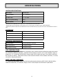
UNITED STATES STOVE COMPANY
“Keeping North America Warm
Since 1869”
Ashley Heritage
MODEL 5700
OWNER’S MANUAL
ÌPlease read this entire manual before installation and use of this appliance. Failure to follow these instructions could result in property damage, bodily injury, or even death.
ÌContact your local building or fire officials about restrictions and installation inspection
requirements in your area.
ÌSave these instructions.
UNITED STATES STOVE COMPANY
227 INDUSTRIAL PARK ROAD
SOUTH PITTSBURG, TENNESSEE 37380
WWW.USSTOVE.COM
FOR TECHNICAL ASSISTANCE:
-- (800) 750-2723
PHONE:
FAX: (423) 837-2109
5700 rev 1
Part No 851606A
TABLE OF CONTENTS
TABLE OF CONTENTS .................................................................................................................2
SAFETY PRECAUTIONS...............................................................................................................3
SPECIFICATIONS .......................................................................................................................5
Heating Specifications .............................................................................................................5
Dimensions.............................................................................................................................5
Electrical Specifications............................................................................................................5
Fuel Considerations .................................................................................................................5
Safety and EPA Compliance .....................................................................................................5
INSTALLATION ..........................................................................................................................6
Installation Options ................................................................................................................ 6
Floor Protection ..................................................................................................................... 6
Clearances ............................................................................................................................ 7
Venting Requirements .............................................................................................................8
Maximum Venting Distance......................................................................................................8
Pellet Vent Type......................................................................................................................8
Pellet Vent Installation ............................................................................................................8
Pellet Vent Termination ...........................................................................................................8
Vent Termination Clearances ...................................................................................................9
Through the Wall Installation.................................................................................................10
Through the Roof/Ceiling Installation ..................................................................................... 10
Outside Air Supply................................................................................................................. 11
Special Mobile Home Requirements........................................................................................ 12
OPERATION..............................................................................................................................13
How Your Stove Works..........................................................................................................13
Control Panel ........................................................................................................................ 14
Unit Preparation.................................................................................................................... 14
Performing a “Dry Run” ......................................................................................................... 14
Start-Up Procedure ............................................................................................................... 15
Shut Down Procedure............................................................................................................ 15
Daily Operation ..................................................................................................................... 16
Safety and Convenience Features........................................................................................... 16
MAINTENANCE .........................................................................................................................17
Exhaust System .................................................................................................................... 17
Interior Chambers ................................................................................................................. 17
Ash Disposal ......................................................................................................................... 17
Check and Clean the Hopper.................................................................................................. 17
Main Door Gaskets ................................................................................................................ 17
Fan Motors ........................................................................................................................... 17
Painted Surfaces ................................................................................................................... 17
Glass .................................................................................................................................... 18
Fall Start-Up ......................................................................................................................... 18
Spring Shut Down ................................................................................................................. 18
Yearly Servicing .................................................................................................................... 18
TROUBLE SHOOTING ...............................................................................................................20
REPAIR PARTS DIAGRAM ........................................................................................................22
REPAIR PARTS LIST .................................................................................................................23
WIRING DIAGRAM ...................................................................................................................24
FACTORY DEFAULTS.................................................................................................................25
SERVICE RECORD.....................................................................................................................26
-2-
SAFETY PRECAUTIONS
ÌIMPORTANT: Read this entire manual before
ÌDisconnect the power cord before performing
installing and operating this product. Failure
to do so may result in property damage, bodily
injury, or even death. Proper installation of
this stove is crucial for safe and efficient operation.
any maintenance! NOTE: Turning the ON/OFF
Switch to ”OFF” does not disconnect all power
to the electrical components of the stove.
ÌNever try to repair or replace any part of the
stove unless instructions for doing so are
given in this manual. All other work should be
done by a trained technician.
ÌInstall vent at clearances specified by the vent
manufacturer.
ÌDo not connect the pellet vent to a vent serving ÌAllow the stove to cool before performing any
any other appliance or stove.
maintenance or cleaning. Ashes must be disposed in a metal container with a tight fitting
lid. The closed container of ashes should be
placed on a non-combustible surface or on the
ground, well away from all combustible materials, pending final disposal.
ÌDo not install a flue damper in the exhaust
venting system of this unit.
ÌUse of outside air is required for this unit.
ÌContact your local building officials to obtain a
permit and information on any additional installation restrictions or inspection requirements in your area.
ÌDo not throw this manual away. This manual
ÌThe exhaust system should be checked monthly
during the burning season for any build-up of
soot or creosote.
ÌDo not touch the hot surfaces of the stove.
Educate all children on the dangers of a hightemperature stove. Young children should be
supervised when they are in the same room as
the stove.
has important operating and maintenance instructions that you will need at a later time.
Always follow the instructions in this manual.
ÌThis heater is designed and approved for premium hardwood pellet fuel only. Any other
type of fuel burned in this heater will void the
warranty and safety listing.
ÌNever use gasoline, gasoline-type lantern fuel,
kerosene, charcoal lighter fluid, or similar liquids to start or ’freshen up’ a fire in this stove.
Keep all such liquids well away from the stove
while it is in use.
ÌThe hopper and stove top will be hot during operation; therefore, you should always use
some type of hand protection when refueling
your stove.
ÌA power surge protector is required. This unit
must be plugged into a 110 - 120V, 60 Hz
grounded electrical outlet. Do not use an
adapter plug or sever the grounding plug. Do
not route the electrical cord underneath, in
front of, or over the heater. Do not route the
cord in foot traffic areas or pinch the cord under furniture.
ÌA working smoke detector must be installed in
the same room as this product.
ÌThe use of outside air is mandatory for safe operation of this unit.
ÌThe heater will not operate during a power outage. If a power outage does occur, check the
heater for smoke spillage and open a window
if any smoke spills into the room.
ÌDo not unplug the stove if you suspect a malfunction. Turn the ON/OFF SWITCH to ”OFF’
and contact your dealer.
ÌThe feed door, hopper lid, and ash pan must be
closed and sealed during operation.
ÌYour stove requires periodic maintenance and
cleaning (see ”MAINTENANCE ”). Failure to
maintain your stove may lead to improper
and/or unsafe operation.
ÌNever block free airflow through the open vents
of the unit.
-3-
SAFETY PRECAUTIONS
ÌKeep foreign objects out of the hopper.
ÌThe moving parts of this stove are propelled by
high torque electric motors. Keep all body
parts away from the auger while the stove is
plugged into an electrical outlet. These moving parts may begin to move at any time while
the stove is plugged in.
ÌDo not place clothing or other flammable items
on or near this stove.
ÌWhen installed in a mobile home, the stove
must be grounded directly to the steel chassis
and bolted to the floor. WARNING—THIS
UNIT MUST NOT BE INSTALLED IN THE BEDROOM (per HUD requirements). CAUTION—
THE STRUCTURAL INTEGRITY OF THE MOBILE
HOME FLOOR, WALL, AND CEILING/ROOF
MUST BE MAINTAINED.
ÌThis appliance is not intended for commercial
use.
Note: United States Stove Company grants no warranty, implied or stated, for the installation
or maintenance of your stove, and assumes no responsibility of any consequential damage(s).
-4-
SPECIFICATIONS
HEATING SPECIFICATIONS
Heat Output1
38,000 BTU/hr
Heating Capacity2
800 – 2,000 sq ft
Fuel Burn Rate3
1.5 – 4.7 lbs/hr
Burn Time (lowest setting)
24 hrs
Hopper Capacity
50 lbs
1
BTU output will vary depending on the quality of fuel. Use PFI listed fuels for the best results.
2
Heating capacity will vary depending on floor plan layout of your home, degree of insulation, and the outside temperature.
3
Pellet size may effect the actual rate of fuel feed and burn times. Fuel feed rates may vary by as much as 20%. Use PFI listed fuel for best results.
DIMENSIONS
Height
38 3/4 in
Width
24 1/4 in
Depth
25 3/4 in
Weight (empty)
280 lbs
ELECTRICAL SPECIFICATIONS
Electrical Rating
110-120 volts 60 HZ 3.0 amps
Watts (operational)
175 (approximately)
Watts (igniter running)
425 (approximately)
FUEL CONSIDERATIONS
Your Ashley Heritage Model 5700 stove is designed to burn premium hardwood pellets that comply with Associa-
tion of Pellet Fuel Industries standards. (Minimum of 40 lbs density per cubic ft, 1/4” to 5/16” diameter, length no
greater than 1.5”, not less than 8,200 BTU/lb, moisture under 8% by weight, ash under 1% by weight, and salt under 300 parts per million). Pellets that are soft, contain excessive amounts of loose sawdust, have been, or are wet,
will result in reduced performance.
SAFETY AND EPA COMPLIANCE
Your Ashley Heritage Model 5700 stove has been safety tested and listed to ASTM E 1509, (UM) 84-HUD by
OMNI-Test Laboratories, Inc. Beaverton, Oregon, USA. It is also exempt from EPA Phase II requirements.
-5-
INSTALLATION
INSTALLATION OPTIONS
ÌRead this entire manual before you install and use your Ashley Heritage stove. Failure to follow
instructions may result in property damage, bodily injury, or even death!
(See specific installation details for clearances and other installation requirements)
A Freestanding Unit—supported by (4) legs and placed on a non-combustible floor surface in compliance with
clearance requirements for a freestanding stove installation.
An Alcove Unit—supported by (4) legs and placed on a non-combustible floor surface in compliance with clearance
requirements for an alcove installation.
Your Ashley Heritage Model 5700 stove may be installed to code in either a conventional or mobile home
(see SPECIAL MOBILE HOME REQUIREMENTS).
It is recommended that only a authorized technician install your Ashley Heritage stove, preferably an NFI certified
specialist.
IMPROPER INSTALLATION: The manufacturer will not be held responsible for damage caused by the
malfunction of a stove due to improper venting or installation. Call (800) 750-2723 and/or consult a professional installer if you have any questions.
FLOOR PROTECTION
This unit must be installed on a non-combustible floor surface. If a floor pad is used, it should be UL listed or equal.
The floor pad or non-combustible surface should be large enough to extend a minimum of 6-inches in front, 6inches on each side, and 1-inch behind the stove (see FIGURE 1).
Floor protection must extend under and 2-inches to each side of the chimney tee for an interior vertical installation
(see FIGURE 2).
Your Ashley Heritage Model 5700 stove will need a minimum 36 1/4” x 30 3/8” floor protector.
FIGURE 1
THROUGH THE WALL INSTALLATION
FIGURE 2
CLEARANCES
-6-
INTERIOR VERTICAL INSTALLATION
INSTALLATION
Your Ashley Heritage Model 5700 stove has been tested and listed for installation in residential, mobile home, and
alcove applications in accordance with the clearances given in FIGURES 3-5 and TABLE 1.
NOTE: Distance “C” on the right-hand side of your Ashley Heritage Model 5700 stove may need
to be greater than the minimum required clearance for suitable access to the control panel.
FIGURE 3
FIGURE 4
SIDEWALL CLEARANCES
PARALLEL INSTALLATION
SIDEWALL CLEARANCES
CORNER INSTALLATION
A—BACKWALL TO UNIT
3 IN / 75 MM
B—SIDEWALL TO FLUE
12 IN / 305 MM
C—SIDEWALL TO TOP EDGE OF UNIT
10 IN / 254 MM
CORNER
D—ADJACENT WALL TO UNIT
10 IN / 254 MM
ALCOVE
E—ALCOVE DEPTH
36 IN / 914 MM
F—ALCOVE HEIGHT
60 IN / 1520 MM
PARALLEL
TABLE 1
CLEARANCES
FIGURE 5
ALCOVE CLEARANCES
VENTING REQUIREMENTS
-7-
INSTALLATION
ÌInstall vent at clearances specified by the vent manufacturer.
ÌDo not connect the pellet vent to a vent serving any other appliance or stove.
ÌDo not install a flue damper in the exhaust venting system of this unit.
The following installation guidelines must be followed to ensure conformity with both the safety listing of this stove
and to local building codes.
IMPORTANT! This unit is equipped with a negative draft system that pulls air through the burn pot
and pushes the exhaust out of the dwelling. If this unit is connected to a flue system other than the
way explained in this manual, it will not function properly.
MAXIMUM VENTING DISTANCE
Installation MUST include at least 3-feet of vertical pipe. This will create some natural draft to reduce the possibility
of smoke or odor during appliance shutdown and keep exhaust from causing a nuisance or hazard by exposing people or shrubs to high temperatures. The maximum recommend vertical venting height is 12-feet for 3-inch type
“PL” vent. Total length of horizontal vent MUST NOT exceed 4-feet. Use no more than 180 degrees of elbows (two
90-degree elbows, or two 45-degree and one 90-degree elbow, etc.) to maintain adequate draft.
PELLET VENT TYPE
A UL listed 3-inch or 4-inch type “PL” pellet vent exhaust system must be used for installation and attached to the
pipe connector provided on the back of the stove (use a 3-inch to 4-inch adapter for 4-inch pipe). Use 4-inch vent if
the vent height is over 12-feet or if the installation is over 2,500 feet above sea level.
We recommend the use of Simpson Dura-Vent® or Metal-Fab® pipe (if you use other pipe, consult your local building codes and/or building inspectors). Do not use Type-B Gas Vent pipe or galvanized pipe with this unit. The pellet
vent pipe is designed to disassemble for cleaning and should be checked several times during the burning season.
Pellet vent pipe is not furnished with the unit and must be purchased separately.
PELLET VENT INSTALLATION
The installation must include a clean-out tee to enable collection of fly ash and to permit periodic cleaning of the
exhaust system. 90-degree elbows accumulate fly ash and soot thereby reducing exhaust flow and performance of
the stove. Each elbow or tee reduces draft potential by 30% to 50%.
All joints in the vent system must be fastened by at least 3 screws, and all joints must be sealed with HI-TEMP RTV
silicone sealant to be airtight. The area where the vent pipe penetrates to the exterior of the home must be sealed
with silicone or other means to maintain the vapor barrier between the exterior and the interior of the home.
Vent surfaces can get hot enough to cause burns if touched by children. Noncombustible shielding or guards may be
required.
PELLET VENT TERMINATION
Do not terminate the vent in an enclosed or semi-enclosed area, such as; carport, garage, attic, crawl space, under
a sundeck or porch, narrow walkway, or any other location that can build up a concentration of fumes.
The termination must exhaust above the outside air inlet elevation.
The termination must not be located where it will become plugged by snow or other materials.
-8-
INSTALLATION
VENT TERMINATION CLEARANCES:
A)
B)
C)
D)
E)
F)
G)
H)
I)
Minimum 4-foot clearance below or beside any door or window that opens.
Minimum 1-foot clearance above any door or window that opens.
Minimum 3-foot clearance form any adjacent building.
Minimum 7-foot clearance from any grade when adjacent to public walkways.
Minimum 2-foot clearance above any grass, plants, or other combustible materials.
Minimum 3-foot clearance from an forced air intake of any appliance.
Minimum 2-foot clearance below eves or overhang.
Minimum 1-foot clearance horizontally from combustible wall.
Must be a minimum of 36-inches above the roof and 24-inches above the highest point or the roof within 10feet.
I
A
F
B
C
H
D
F
A
E
FIGURE 6
VENT TERMINATION CLEARANCES
-9-
INSTALLATION
THROUGH THE WALL INSTALLATION
(RECOMMENDED INSTALLATION)
To vent the unit through the wall, connect the pipe
adapter to the exhaust motor adapter. If the exhaust
adapter is at least 18-inches above ground level, a
straight section of pellet vent pipe can be used through
the wall.
Your Ashley Heritage dealer should be able to provide
you with a kit that will handle most of this installation,
which will include a wall thimble that will allow the
proper clearance through a combustible wall. Once outside the structure, a 3-inch clearance should be maintained from the outside wall and a clean out tee should
be placed on the pipe with a 90-degree turn away from
the house. At this point, a 3-foot (minimum) section of
pipe should be added with a horizontal cap, which would
complete the installation (see FIGURE 7).
A support bracket should be placed just below the termination cap or one every 4-feet to make the system more
stable. If you live in an area that has heavy snowfall, it
is recommended that the installation be taller than 3-feet
to get above the snowdrift line. This same installation
can be used if your stove is below ground level by simply
adding the clean-out section and vertical pipe inside until
ground level is reached. With this installation you have
to be aware of the snowdrift line, dead grass, and
leaves. We recommend a 3-foot minimum vertical rise
on the inside or outside of the house.
FIGURE 7
TYPICAL THROUGH THE WALL INSTALLATION
The “through the wall” installation is the least expensive and simplest installation. Never terminate the end
vent under a deck, in an alcove, under a window, or between two windows. We recommend Simpson Dura-Vent®
or Metal-Fab® kits.
THROUGH THE ROOF/CEILING INSTALLATION
When venting the stove through the ceiling, the pipe is connected the same as through the wall, except the cleanout tee is always on the inside of the house, and a 3-inch adapter is added before the clean-out tee.
You must use the proper ceiling support flanges and roof flashing (supplied by the pipe manufacturer; follow the
pipe manufacturer’s directions). It is important to note that if your vertical run of pipe is more than 15-feet, the
pellet vent pipe size should be increased to 4-inches in diameter.
Do not exceed more than 4-feet of pipe on a horizontal run and use as few elbows as possible. If an offset is required, it is better to install 45-degree elbows rather than 90-degree elbows.
-10-
INSTALLATION
OUTSIDE AIR SUPPLY
ÌThe use of outside air is mandatory for safe operation of this unit.
For all installations it is mandatory that this unit be connected to an outside air supply .
Metal pipe (solid or flexible) must be used for the outside air installation. PVC pipe is NOT approved and should
NEVER be used.
A wind shield over the termination of the outside air pipe or a 90-degree elbow or bend away from the prevailing
winds MUST be used when an outside air pipe is installed through the side of a building. The outside air termination
MUST be at least 1-foot away from the exhaust system termination.
The outside air pipe on your Ashley Heritage Model 5700 stove is 1 7/8” OD. The outside air connecting pipe
must be at least 1 7/8” ID. The outside air connection used MUST NOT restrict the amount of air available to your
stove. The outside air connecting pipe must be as short and free of bends as possible, and it must fit over, not inside, the outside air connection to the stove (USSC Part No FAK1780 Fresh Air Kit is recommended).
WIND HOOD
1 7/8” ID
2” MIN
WIRE MESH
SCREEN
FIGURE 9
TYPICAL OUTSIDE AIR TERMINATION
FIGURE 8
EXHAUST/INLET LOCATIONS
NOTE: Dimensions from the floor to your
stoves inlet/exhaust pipes are approximate and
may vary depending on your installation.
-11-
INSTALLATION
SPECIAL MOBILE HOME REQUIREMENTS
ÌWARNING! - DO NOT INSTALL IN A SLEEPING ROOM
ÌCAUTION! - THE STRUCTURAL INTEGRITY OF THE MOBILE HOME FLOOR, WALL, AND CEILING/
ROOF MUST BE MAINTAINED.
In addition to the previously detailed installation requirements, mobile home installations must meet the following
requirements:
•The stove must be permanently attached to the floor.
•The stove must have a permanent outside air source (USSC Part No FAK1780 Fresh Air Kit is recommended).
•The stove must be electrically grounded to the steel chassis of the mobile home with 8 GA copper wire using a serrated or star washer to penetrate paint or protective coating to ensure grounding.
•Vent must be 3 or 4-inch “PL” Vent and must extend a minimum or 36-inches above the roofline of the mobile
home and must be installed using a UL/ULC listed ceiling fire stop and rain cap.
•When moving your mobile home, all exterior venting must be removed while the mobile home is being relocated.
After relocation, all venting must be reinstalled and securely fastened.
•Check with your local building officials as other codes may apply.
-12-
OPERATION
ÌDo not operate your stove with the viewing or ash pan doors open. The upper auger will not feed
pellets under these circumstances and a safety concern may arise from sparks or fumes entering
the room.
ÌThis heater is designed and approved for premium hardwood pellet fuel only. Any other type of fuel
burned in this heater will void the warranty and safety listing.
ÌA working smoke detector must be installed in the same room as this product.
HOW YOUR STOVE WORKS
Your Ashley Heritage Model 5700 stove utilizes a dual au-
ger fuel feed system that is operated by a microprocessor controlled digital circuit board. The digital circuit board allows the
dual auger fuel feed system to run in a timer-based, noncontinuous cycle; this cycling allows the top auger to run for a
predetermined period of seconds, while the bottom auger operates continuously. The top auger drops pellets to the bottom
auger, while the bottom auger pushes the pellets forward to
the burn pot. As pellets enter the burn pot, outside air is
drawn across the fuel and heated during the combustion process. This heated combustion air is then pulled through the
heat exchanger by the exhaust blower, where it is used to heat
air that is drawn into the heat exchanger system by the room
air fan (see FIGURE 10).
Because a forced draft pressure is required for the combustion
process inside your stove, it is extremely important that the
exhaust system be properly installed and maintained. And,
that when operating your stove, you make sure that the hopper lid, door, and ash pan slides are all properly sealed.
Your stove’s heat output can vary from hi to low by adjusting
the settings on the control panel (located on the lower righthand side of the stove). The “HEAT RANGE” setting will vary
FIGURE 10
the auger systems feed rate and the exhaust blower speed (i.e.
HOW YOUR STOVE WORKS
combustion air). The “BLOWER SPEED” setting will adjust
the room air fan speed (i.e. convection air). Each setting has a
range of 1 to 9 (lowest to highest). Any combination of “HEAT RANGE” and “BLOWER SPEED” can be used during the operation of your stove.
Your stove can run efficiently over extended periods of time and at different heat output levels as long as the fuel
supply is uninterrupted and proper cleaning and maintenance is performed. (NOTE: Operating your stove on
a high “HEAT RANGE” setting and a low “BLOWER SPEED” setting for extended periods of time may cause your
stove to reach an over-temperature condition, in which case, the stove will automatically reduce the fuel feed rate
and/or increase the room air fan speed. This is a safety precaution that has been designed into your stove and is
not a malfunction).
-13-
OPERATION
CONTROL PANEL
Turning the stove OFF/ON, as well as adjustments for the fuel feed rate and room air fan
speed are performed by pressing the appropriate button(s) on the control panel which is located on the
lower right-hand side of your Ashley Heritage Model
5700 stove (see FIGURE 11).
Pressing the “ON” button on the control panel will begin the start-up sequence for the stove. Fuel will begin
to feed through the auger feed system and, once an
adequate amount of fuel has been deposited into the
burn pot, the auto-start igniter will ignite the fuel.
Pressing the up/down arrow buttons beneath the
“HEAT RANGE” and “BLOWER SPEED” will adjust
the amount of fuel that is fed to the burn pot and the
amount of room air drawn through the stove to be
heated, respectively. Either value can be set from 1 to
9 (lowest to highest).
FIGURE 11
DIGITAL CONTROL PANEL
Pressing the “OFF” button on the control panel will
cause the stove to enter its shut-down sequence. The fuel feed system will stop pulling fuel from the hopper and,
once the fire goes out and the stove cools down, the lower auger and all of the blowers will stop running.
The “A”, “B”, and “C” buttons on the control panel are reserved for diagnostic use only. These controls are disabled by default when the unit is shipped from our factory.
UNIT PREPARATION
After carefully unpacking and reading the instructions for installing your stove, you will need to perform the following steps:
1) Attach the two (2) included spring handles; one (1) for the door handle and (1) ash pan slide lever by screwing
them on in their respective locations.
2) Adjust the legs as necessary so that the stove is sitting level on the floor.
3) Locate and attach the firewall impingement plate inside the stove (see FIGURE 12).
4) Attach the electrical cord to the back of the stove first; then plug it into a 110-volt outlet (an outlet surge protector is highly recommended).
5) Check that the hopper lid latch is properly adjusted so as to create a tight fit between the hopper lid and hopper.
Important: Hopper Lid Latch must be tight so that the hopper is sealed airtight while
the stove is operating, failure to do so may result in a hopper fire.
PERFORMING A “DRY RUN”
Perform a “dry run” on your stove prior to making the exhaust/inlet connections and starting your stove for the first
time.
1) Check that there is NO fuel in the hopper or burn-pot.
2) Check that the hopper lid, viewing door, and ash pan slides are securely closed.
3) Press the “ON” button on the control panel. This will start the upper auger, bottom auger, and exhaust blower.
-14-
OPERATION
4) Check that both augers and the exhaust blower are operating (the room air blower will not start at this time).
DO NOT open the viewing door, the auto-start igniter will get very hot during this test. The stove will automatically shut down after approximately 23 minutes.
START-UP PROCEDURE
ÌNever use gasoline, gasoline-type lantern fuel, kerosene, charcoal lighter fluid, or similar liquids to
start or ’freshen up’ a fire in this stove. Keep all such liquids well away from the stove while it is in
use.
1) Verify that the hopper is clean and free of foreign matter.
2) Verify that all of the required exhaust/inlet connections have been made in accordance with this manual and
that the stove is plugged into an outlet (an outlet surge protector is highly recommended).
3) Fill the hopper with wood pellets; do not allow any part of the bag or any other foreign material into the hopper,
as this may jam the augers.
4) Ensure that all pellet matter is cleared from the hopper gasket seating surface.
5) Close the hopper lid and secure the latch.
6) Make sure that the viewing door and ash pan slides are securely closed (the safety pressure switch will not allow
the stove to feed fuel if there is no draft pressure inside the stove) .
7) Press the “ON” button on the control pad and set the “HEAT SETTING” to “5”.
8) The stove will begin to feed fuel and the auto-start igniter will ignite the fuel in approximately 5 minutes.
Once a consistent flame has been established, you can adjust the “HEAT RANGE” and “BLOWER SPEED” on the
control pad to your desired settings. (Note: The room air fan will not function until the heat exchanger in the stove
reaches the factory preset temperature).
First Fire: Adjust the “HEAT RANGE” and “BLOWER SPEED” to a “5” setting and allow the stove to
operate in this manner for approximately three (3) hours (or more if necessary), allowing the stove to “cure
out” as the paint and oils from the manufacturing process burn off. We recommend that you open doors
and windows in your home during this process.
SHUT DOWN PROCEDURE
WARNING: Never shut down this unit by unplugging it from the power source.
Press the “OFF” button on the control pad to put the stove in shut down mode. At this time, the red light above the
pad will illuminate. Once this is done, the top auger will stop feeding pellets to the bottom auger, but the room air
fan, exhaust blower, and bottom auger will continue to operate. When the internal temperature of the unit drops
below the factory preset temperature, the room air fan, exhaust blower, and bottom auger will cease to operate.
The red light will then shut off and the unit will be completely shut down.
The hotter the unit is during its operation, the longer it will take for the stove to complete the shut down cycle. If
the stove stays on for more than 2 hours after pressing the “OFF” button and you are sure that the fire is out, the
stove can be unplugged from the outlet. After approximately 10 seconds, the unit can be re-connected to the
power source and the control board will be reset.
-15-
OPERATION
DAILY OPERATION
ÌThe hopper and stove top will be hot during operation; therefore, you should always use some type
of hand protection when refueling your stove.
ÌNever place your hand near the auger while the stove is in operation.
This unit has a 50-pound hopper and should be filled when the hopper level drops below 3-inches.
Ensure that all pellet matter is cleared from the hopper gasket surface before closing. Be sure to close hopper securely after refueling. Do not operate this unit with the hopper lid open or unsecured.
In the event of a power outage, the stove WILL NOT function. It is very important that unit be vented properly
(with outside air), as the natural draft is needed to clear the smoke from the stove during a power outage. Also, DO
NOT open the hopper lid because this may allow fire to burn-back into the hopper. If the unit was “ON” when the
power outage occured, one of the following will take place:
1) If the stove is still warm, it will resume feeding fuel and continue to operate normally. If the fire has gone out,
you will have to press the “OFF” button and then the “ON” button again to begin a new start-up sequence.
2) If the stove has cooled-off, it will reset to its “OFF” condition. At this point, you may press the “ON” button
and the unit will begin a new start-up sequence.
NOTE: The unit will also shut down in the event of an exhaust blower failure; if this is the case, the unit will not restart and you must contact Customer Service at (800) 750-2723.
SAFETY AND CONVENIENCE FEATURES
Your Ashley Heritage Model 5700 incorporates a safety pressure switch that helps ensure that everything is
in proper working order before feeding fuel to the burn pot. Because the stove works using an induced draft pressure, the stove will not continue to operate if the viewing door or ash pan slides are left open; or if the combustion
blower fails or the exhaust system is blocked.
The temperature limit control will prevent your stove from operating at abnormally high temperatures. Should
the stove temperature begin to approach the factory pre-set limit, the temperature limit control will automatically
slow down the auger feed rate until the temperature returns to a normal condition.
Your Ashley Heritage Model 5700 stove also includes an auto-start igniter as a standard feature. The use of
other fire starter materials (wood chips, starter gel, etc.) is not necessary. By simply pressing the “ON” button on
the digital control panel, your stove will begin to feed fuel and automatically start within 5 minutes.
Additionally, your Ashley Heritage Model 5700 stove includes an integral ash pan, making the cleaning and
removal of ash less frequent and more convenient
-16-
MAINTENANCE
ÌFailure to clean and maintain this unit as indicated can result in poor performance and safety hazards.
ÌUnplug your stove’s electrical cord prior to removing the back panel or opening the exhaust system
for any inspection, cleaning, or maintenance work.
ÌNever perform any inspections, cleaning, or maintenance on a hot stove.
ÌDo not operate stove with broken glass , leakage of flue gas may result.
EXHAUST SYSTEM
The by products of combustion contain small particles of fly ash. Fly ash will collect in the exhaust venting system
and restrict the flow of flue gases. Incomplete combustion, such as during startup, shutdown, or incorrect operation
of the stove will lead to soot formation which will collect in the exhaust system. Therefore, it is important that the
exhaust system be inspected and cleaned at least monthly during the burning season.
Check the clean out tees periodically to determine the required cleaning schedule. 3 or 4-inch chimney brushes are
available for chimney cleaning. If the exhaust system or outside air pipes have screens on them, frequently clean
the screen. A plugged screen will shut off combustion air and cause a fire to die or burn poorly.
INTERIOR CHAMBERS
Periodically remove and clean the burn plate and the area inside the burn pot. In particular it is advisable to clean
out the holes in the burn plate to remove any build up that may prevent air from moving through the burn pot
freely. When replacing the burn plate, be sure that it is properly seated in the burn pot. (NOTE: It is not necessary
to remove the burn pot for normal cleaning, if you do, you MUST replace the gasket that goes between the burn pot
and firewall.)
Remove the firewall impingement plate and clean any ash that may have collected in the heat exchanger system.
If a vacuum is used to clean your stove, we suggest using a vacuum designed for ash removal. Some regular vacuum cleaner (i.e. shop vacs) may leak ash into the room.
ASH DISPOSAL
Remove the ash pan and dump the ash as needed. (NOTE: Ashes should be placed in a metal container with a
tight fitting lid. Place the container on a non-combustible surface well away from all combustible materials. Retain
all ash material in the container until all cinders have thoroughly cooled.)
CHECK AND CLEAN THE HOPPER
Check the hopper periodically to determine if there is any sawdust or pellets that are sticking to the hopper surface.
Clean as needed.
MAIN DOOR GASKETS
Inspect the main door and glass window gaskets periodically. The main door may need to be removed to have
frayed, broken, or compacted gaskets replaced by your Authorized “Ashley Heritage” Dealer.
FAN MOTORS
Clean the air holes on the motors of both the exhaust and room air fans annually. Remove the exhaust blower from
the exhaust duct and clean out the internal fan blades as part of your fall start-up.
PAINTED SURFACES
Painted surfaces may be wiped down with a damp cloth. If scratches appear, or you wish to renew your paint, con-17-
MAINTENANCE
tact your Authorized “Ashley Heritage” Dealer to obtain a can of suitable high-temperature paint.
GLASS
We recommend using a high quality glass cleaner. Should a build up of creosote or carbon accumulate, you may
wish to use 000 steel wool and water to clean the glass. In the event you need to replace the glass, only high temperature ceramic glass of the correct size and thickness may be used. Contact your Authorized “Ashley Heritage”
Dealer to obtain this glass.
FALL START UP
Prior to starting the first fire of the heating season, check the outside area around the exhaust and air intake systems for obstructions. Clean and remove any fly ash from the exhaust venting system. Clean any screens on the
exhaust system and on the outside air intake pipe. Turn all of the controls on and make sure that they are working
properly. This is also a good time to give the entire stove a good cleaning throughout.
SPRING SHUTDOWN
After the last burn in the spring, remove any remaining pellets from the hopper and the auger feed system. Scoop
out the pellets and then run the auger until the hopper is empty and pellets stop flowing (this can be done by pressing the “ON” button with the viewing door open). Vacuum out the hopper. Thoroughly clean the burn grate, firebox, ash pan and ash traps. It may be desirable to spray the inside of the cleaned hopper with an aerosol silicone
spray if your stove is in a high humidity area. The exhaust system should be thoroughly cleaned.
YEARLY SERVICING
A yearly servicing and cleaning by your Authorized “Ashley Heritage” Dealer is recommended. A fee may be
charged for this service.
-18-
MAINTENANCE
FIGURE 12
MAINTENANCE PARTS DIAGRAM
-19-
TROUBLE SHOOTING
ÌDisconnect the power cord before performing any maintenance! NOTE: Turning the ON/OFF Switch
to ”OFF” does not disconnect all power to the electrical components of the stove.
ÌNever try to repair or replace any part of the stove unless instructions for doing so are given in this
manual. All other work should be done by a trained technician.
PROBLEM
CAUSE:
Too rich air/fuel mixture
Orange, lazy flame—excessive •Clean out the burn plate and burn pot.
fuel build-up in the burn pot
•Check that the ash pan slides are completely closed.
•Make sure that the viewing door is shut and sealed tightly. If not, adjust the door
catch and/or replace the gaskets.
•Check that the outside air connection is clear of any obstructions.
•Check that the hopper lid is sealed tightly.
•Check the exhaust system, clean as needed.
PROBLEM
CAUSE:
Firepot burns out of fuel
Fire goes out or stove shuts
•Hopper is empty, refill the hopper.
down. Lower auger turns, but
•Loss of draft pressure. Check that the main door, ash pan slides, and hopper lid are
no fuel is feeding.
all sealed tightly. Check that the outside air connection is clean and clear of any
obstructions. Check the exhaust system, clean as needed.
•Auger system is jammed or there is “bridging” of the fuel in the hopper, preventing
fuel from flowing into the auger feed system.
PROBLEM
CAUSE:
Auto-Start Igniter fails to ignite the fuel in the burn pot
Stove does not start a fire
•Turn the stove “OFF”. Clear the unspent fuel from the burn pot and try again.
when “ON” button is pushed.
•Check the pellet quality. Replace if moist, wet, or dirty.
•Loss of draft pressure. Check that the main door, ash pan slides, and hopper lid are
all sealed tightly. Check that the outside air connection is clean and clear of any
obstructions. Check the exhaust system, clean as needed. The safety pressure
switch will not supply power to the auto-start igniter if there isn’t sufficient
draft pressure inside the stove.
•Check that the auto-start igniter is not blocked with ash or soot (the igniter is
located behind the 3/8” diameter hole located on the back wall of the burn pot).
NOTE: The gasket between the burn pot and rear firewall is critical for the flow
of hot air from the auto-start igniter into the burn pot. If you have previously
removed the burn pot, this gasket must be replaced.
•The Auto-Start Igniter gets “red hot” during start-up. If you can not visibly see the
igniter glowing during start-up, then the auto-start igniter may need to be replaced or there is a problem with the electrical control system.
-20-
TROUBLE SHOOTING
-21-
REPAIR PARTS DIAGRAM—MODEL 5700
-22-
REPAIR PARTS LIST—MODEL 5700
ITEM
PART NO.
DESCRIPTION
ITEM
PART NO.
1
69465B
Main Weldment
23
40488
DESCRIPTION
Auger Housing
2
69461
Impingement Plate Weldment
24
40489
Auger, Short
3
69462
Ash Dump Weldment
25
40490
Auger, Long
4
25361
Guide, Ash Dump Rod
26
88101
Gasket, Mounted Bearing
5
89954
Spring Handle
27
891105
Mounted Bearing
6
69466
Hopper Weldment
28
25370
Stop, Auger Motor
7
88110
Gasket, Hopper Bottom
29
891117
Shaft Collar, 3/4" ID
8
69463B
Ash Pan Weldment
30
83045
Washer
9
89899
Knob
31
83337
5/16-18 x 1-1/4 Bolt
10
891122
Burnpot Weldment
32
80474
Auger Motor
11
88102
Gasket, Burnpot
33
86613
Air Intake Tube
12
25355
Burn Plate
34
80481
Ignitor Cartridge
13
83475
5/16-18 x 1-3/4 Bolt
35
80472
Blower, Distribution
14
25080B
Latch, Door
36
88106
Gasket, Distribution Blower
15
69467
Feed Door Assembly
37
88107
Insulation, Exhaust Chute
15.1
25266
Feed Door
38
80473
Blower, Exhaust
15.2
891067
Door Glass w/Ashley Logo
39
88100
Gasket, Exhaust Blower
15.3
88087
Glass Gasket (1 x 3/16)
40
25377B
Blower Access Cover
15.4
25393
Glass Retainer
41
80478
Pressure Switch
15.5
88066
5/8 Rope Gasket
42
891121
Silicone Tube
15.6
25452
Handle, Door
43
89586
Auger Nipple
15.7
83506
3/8 x 1-1/4 Roll Pin
44
25344B
Back, Cabinet
15.8
89574
Handle, Brass Spring
45
80462
Recepticle, 3 Prong
16
69464B
Cabinet Top-Front Weldment
46
80461
Power Supply Cord
17
69471B
Cabinet Top-Lid Weldment
18
88109
Seal, Hopper Lid
19
891125
Latch, Hopper Lid
20
80475
Circuit Board Assembly
21
80480
Temperature Sensor
22
83524
5/16-18 x 1 Flat Head Socket Cap Screw
HOW TO ORDER REPAIR PARTS
When inquiring about spare parts, always give the full model number which is on the nameplate attached to the
back of the unit.
The following information is needed when ordering spare parts:
1) Part Number:
2) Part Description:
3) Model Number:
5700
4) Serial Number:
United States Stove Company
227 Industrial Park Road
PO Box 151
South Pittsburg, TN 37380
(888) 299-1440 (Parts Department)
www.usstove.com
-23-
WIRING DIAGRAM
-24-
FACTORY DEFAULTS
FACTORY DEFAULT SETTINGS
Setting
Description
Default
Value
(P1) Auger Period
Time limit for the upper auger period of
operation. Display in is 1/10th sec.
16 sec
(P2) Cold Stove Temp
Low temperature limit that a warm stove
must reach in order to shut down completely.
95 deg F
(P3) Hot Stove Temp
Maximum temperature limit that the stove
is allowed to reach before ceasing to feed
fuel.
350 deg F
(P4) Hot Stove Hysterisis
Temperature differential below the Hot
Stove Temp that the stove must reach before resuming operation.
1 deg F
(P5) Room Air On Temp
Minimum temperature that the stove must
reach before the room air fan will operate.
115 deg F
(P6) Auger Load Time
Time limit that the auger will feed fuel dur- 15 sec
ing the start-up sequence prior to engaging the automatic igniter.
(P7) Igniter On Time
Time limit that the automatic igniter is engaged during the start-up sequence.
8 min
(P8) Start-Up Time
Time limit that the stove will be allowed to
operate before the Room Air On Temp
must be reached.
15 min
(P9) Factory Defaults
Selecting this variable will reset all of the
variables to the factory defaults.
-
(PA) Room Fan On Temp
High temperature limit that will cause the
stove to reduce the fuel feed rate by 25%
and maximize the room air fan speed.
290 deg
(PB) Auger Start Operation
Variable to control the auger fuel feed dur- 0
ing start-up. (0 = On, 1 = Off).
(PC) Auger Operation Select
Variable to set the upper auger period of
operation. (0 = 4 sec, 1 = 6 sec)
-25-
1
SERVICE RECORD
DATE
SERVICE OR CLEANING PERFORMED
-26-
-27-
UNITED STATES STOVE COMPANY
227 INDUSTRIAL PARK ROAD
PO BOX 151
SOUTH PITTSBURG, TN 37380
(800) 750-2723
WWW.USSTOVE.COM
-28-