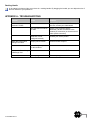
1
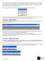
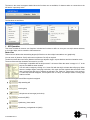
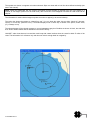
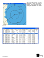
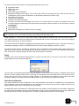
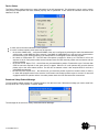
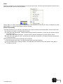
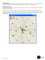
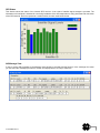
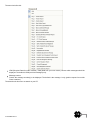
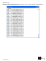
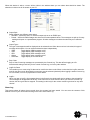
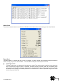
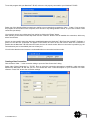
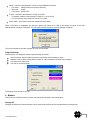
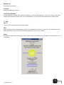
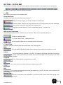
In the United States
WARNING: It is a violation of the rules of the Federal Communications Commission to
input an MMSI that has not been properly assigned to the end user, or to otherwise input any inaccurate data in this
device.
WARNING: This product is a supplemental navigation tool only! The user assumes all responsibility associated with
the use of this device and safe navigation.
It is important to understand that all vessels may not be equipped with AIS transponders and therefore are not visible to
this transponder. Likewise, certain conditions, such as equipment failures, the environment, improper use and crowded
port scenarios, may exist whereby the vessel equipped with this AIS transponder is not visible to other AIS transponders.
CAUTION: Before proceeding to install, test or use your new ACR Electronics product, please read this
Product Support Manual in its entirety.
If you have questions regarding the contents of the manual, please contact our Technical Service Department at
ACR Electronics, Inc., Telephone +1 (954) 981-3333. Please be ready to provide the technician with the page
number you wish to discuss. If you have a question that is not covered in the manual, please visit our website and
access the Frequently Asked Questions (FAQs) section for further information or call our Technical Service
Department. The website address is www.acrelectronics.com. If in the future you lose this manual, you may access
and print a replacement on the ACR website.
2
Y1-03-0223 Rev. D
Table of Contents
SECTION 1 - INSTALLATION _________________________________________________ 4
SECTION 2 - STARTING THE LINK2AIS™ SOFTWARE ___________________________ 4
SECTION 3 - MAIN WINDOW _________________________________________________ 5
SECTION 4 - MENU STRUCTURE _____________________________________________ 5
SECTION 5 - STATUS BAR _________________________________________________ 23
APPENDIX A - TROUBLESHOOTING__________________________________________ 25
APPENDIX B - SUPPORT, WARRANTY, USEFUL LIFE and NOTICES _______________ 26
PLEASE READ ALL WARNINGS,
CAUTIONS AND NOTES CAREFULLY
3
Y1-03-0223 Rev. D
SECTION 1 - INSTALLATION
For detailed instructions on how to install the Link2AIS™ software, please refer to the product support manual provided
with this product.
SECTION 2 - STARTING THE LINK2AIS™ SOFTWARE
When starting the program, it welcomes you and asks for a connection (see also “Connect / Disconnect”).
Select one of the already defined connections in the drop-down list or define a new connection by clicking the “New…”
button as described in “Creating a New Connection”, page 21. When the selection has been made, press “Connect” to
start the program.
When you click “Abort Program” or have chosen a connection not available, the program will not be able to communicate
with the device. The following message appears to warn you about this state:
NOTE: The device requires static data to be entered. When connecting to a new AIS device, the static data is most likely
not defined. The program automatically enters the page to define the static ship data. However, the page can be selected
at any time.
In the United States
WARNING: It is a violation of the rules of the Federal Communications Commission to
input an MMSI that has not been properly assigned to the end user, or to otherwise input any inaccurate data in this
device.
Once connected, you can choose any of the pages selectable from the menus.
Many settings will be stored on your PC. When you start the program again, most appearances will be the same as when
you last used the program.
4
Y1-03-0223 Rev. D
By pressing the button "Clear all settings", all settings regarding this program will be removed from your PC and the
program stops execution. This function is useful when you want to completely remove the program from your computer. It
is not necessary to remove the settings when you merely want to update the program. The software is capable of
interpreting the settings as stored by the previous version.
After pressing the button to remove the settings, the program will inform you that this has been done:
Many controls have “Tool Tips” attached to them. For information about a button or setting, let the cursor hover on an item
and wait until a short description for this item pops up. You can easily test this in the status bar.
SECTION 3 - MAIN WINDOW
The main window will hold all views and dialogs of the program. There are some additional controls and indicators to
simplify operating this program.
In the title bar there is the control menu on the far left, the title of the program and the state buttons on the far right where
the program area can be maximized, minimized or the program terminated.
Just below the title bar there is the menu bar that will be described in the section “Menu Structure”.
On the bottom there is the status bar with miscellaneous information of the program and your transponder. The status bar
will be described in the section “Status Bar”.
SECTION 4 - MENU STRUCTURE
The menu is organized hierarchically. Almost all of the functions open a window. The position, size and state (e.g.
maximized) of the windows will be stored on your PC. When you re-open one of the windows it will appear in the same
position, size and state as when you last used this window.
Note that the menu has two states: the normal user state and the expert state. The expert state should only be used when
special functionality contained in the menu “Maintenance” is required. The standard menu looks like this:
When the expert mode has been selected, it looks like this:
5
Y1-03-0223 Rev. D
The items in the menu bar appear shaded when the functions are not available, for instance when no connection to the
AIS device is presently active.
The functions are as follows:
1. AIS Operation
This menu contains all common user functions. Included are functions to define or view your own ship‟s status and data,
to view other ships, and to control the VHF transceiver.
Radar View
This menu item shows other transmitting targets (AIS devices on other ships, base stations etc.) graphically.
You can zoom in (shortcut: Ctrl+I) and zoom out (shortcut: Ctrl+O) as required.
The title bar shows the zoom factor (distance between two adjacent rings) in square brackets and the orientation mode.
The zoom factor and the orientation are stored on your PC.
Each target is identified with the ship‟s name if it is known. When the name is empty or is „?‟ in the
ship list, the MMSI is shown instead.
You can select a target by clicking on it. A text field with the ship‟s relevant data will pop up. When
there are multiple targets overlaying each other, click again until the required data are shown. Note
that a selected ship will also be marked as selected in the “Ship List” (shown later in this section).
To make this text field disappear, click anywhere but on a ship. The example shows a moving ship
with its text field.
The different targets have different symbols assigned:
a ship standing still
a moving ship
a ship shown as lost target (see below)
an aircraft (SAR)
a (stationary ) base station
a (stationary ) navigational aid (AtoN)
6
Y1-03-0223 Rev. D
The symbols are shown in magenta color when selected. Ships are drawn with a bold line when defined as buddy (see
later in this manual).
NOTE: When the transponder has not received a message for 360 seconds (6 minutes) from one of the targets it is
marked as “lost target” (strike out in the radar view). After 10 minutes it will disappear from both the radar view and the
ship list.
The information for each individual target may take some time to appear (up to several minutes).
The radar view shows the targets as “viewed from top”. You can show the radar view as either “North Up” (shortcut:
Ctrl+N) or “Course Up” (shortcut: Ctrl+C). The default display mode is “North Up” as shown in the picture, where north,
(0°), is always on top.
The selected target will be colored magenta on a semi-transparent gray box. Buddies are shown in black, but with thick
lines. How to define buddies will be described in the section “Buddy”.
Link2AIS™ radar view shows a low resolution world map with coastal outlines when the vessel is within 50 miles of the
coast. This information is for reference only and does not include enough detail to navigate by.
7
Y1-03-0223 Rev. D
When “Course Up” is selected, your vessel
always points up and the north direction is
rotated as required. Your current Courseover-Ground is shown by the arrow centered
at the top of the screen.
Ship List
This window shows information received from other AIS-equipped targets in the area (ships, base stations etc.).
8
Y1-03-0223 Rev. D
The columns show the information of a target (each target takes up one row):
Sequential number
MMSI of the target
Type of AIS
Name of the target (if assigned)
Approximate distance to the target. This is only shown when the connected unit has a GPS fix and when the
coordinates are valid. Please note that this is an approximate distance for indication only!
SOG (speed over ground)
COG (course over ground)
Call sign of the target (if assigned)
Time since the last received message from this AIS. The column shows the number of seconds since the last
received message from this target. After 360 seconds (6 minutes) the target is market as “lost” and after 10 minutes
it will disappear.
LAT (latitude)
LON (longitude)
Buddy name if assigned (see “Buddy” section, next page)
NOTE: When you click on a line, the ship becomes selected. It will also be selected in the “Radar View” if it is visible. To
undo a selection, click on a line without a target or to the right of the right-most column.
Fields containing a “?” have not or not yet been received, meaning that the fields have not been filled with valid data. A
“N/A” indicates that the content of this field has been transmitted with no value or the default value or cannot be computed
(e.g. distance with faulty or invalid coordinates).
The column width can be adjusted by dragging the right-hand border of the appropriate column. The columns can also be
rearranged by dragging a column to a different position in the table. These settings are stored on your PC.
All columns can be sorted in ascending or descending order by clicking the column header. When opening the ship list
window, the default sort order is ascending distance. Ships with a distance “N/A” are put on top immediately following your
ship. They may be a pending danger to all other ships, as their position is unknown.
Buddy
A Buddy can be defined by double-clicking either on a ship in the radar view or on a line in the ship list. The following
dialog appears to let you define the Buddy text:
You may enter a text describing the Buddy. This text appears in a tag in the radar view and in a separate column in the
ship list. To delete a Buddy, double-click it on the map or in the ship list, delete the buddy name in the window and click
OK and the ship will revert to normal (not being a Buddy). If the ship has been displayed on the screen after being
designated a Buddy, the software will store the Buddy name on your PC when the program is terminated.
Static Data Configuration
This window shows the current configuration of the AIS transponder and allows the configuration to be programmed
during installation. When an AIS transponder not yet configured is connected for the first time (no MMSI received by the
program) this window will open automatically after a short while.
All configuration data of the Nauticast™-B AIS will be read out in advance to make changes more convenient. By pressing
the “Save” button all settings will be sent to the Nauticast™-B AIS. You will be warned when there are any invalid data
and the data will not be sent to the transponder. For instance, the dimensions must be in the valid range.
9
Y1-03-0223 Rev. D
A Nauticast™-B AIS transponder connected to this program looks like this:
Configuring the Transponder
For instructions on configuring the transponder, please see the Product Support Manual included with this product.
Own Ship Data
This window shows information on the current state of your AIS transponder. A typical response looks like this:
10
Y1-03-0223 Rev. D
Device Status
The Device Status window shows key status information of the AIS transponder. This information can be used to quickly
verify that the transponder has been installed properly and is operational. It also shows the software versions of the
Nauticast™-B AIS.
A check next to the items indicates correct operation.
If a red X is shown instead, some action may be required:
o No check at “MMSI valid” – verify that the MMSI of the unit is configured by selecting the static data window and
verifying that a valid MMSI has been entered. If the MMSI is 000000000 then it has not been programmed or
the connection is not working properly or the transponder is not designed to work with this program.
o No check at “GPS position fix” – the GPS has not acquired a position fix. Allow up to 5 minutes for a fix to be
acquired. If the X is still present after several minutes check the GPS antenna position and connection and the
clear sky visibility.
o No check at “Pos. Report Tx‟d” – the AIS has not yet transmitted its position. Please allow up to 5 minutes after
GPS fix has been acquired for the green check to appear. When the X is still present after several minutes
please refer to the active alarms section. The AIS will not transmit unless it has acquired GPS fix and has a
valid MMSI programmed.
o No check at “Pos. Report Rx‟d” – the AIS has not yet received a position report from another vessel. If there is
no other AIS equipped vessel in the area the X will remain until another position report is received. If other AIS
equipped vessels are present and the X remains please check the VHF antenna and its connections.
Broadcast Safety Related Message
To send a safety related message in a distress situation, click this menu item. Select the message you need to send from
the drop-down list. Then press the “Transmit” button.
The message will be sent as a “Safety Related Broadcast Message”.
11
Y1-03-0223 Rev. D
Silent
With this command you can stop transmissions by using the silent mode. The LEDs will indicate that the AIS device is in
silent mode and the menu item will be checked.
Clicking again on “Silent” reactivates the transmissions. The Nauticast™-B AIS will still receive messages from other
stations when it is in silent mode but will not transmit anything.
Switch Functionality
The switch connected to your AIS device can perform one of several functions as described below, selected in this menu.
No switch or no action – the switch has no function.
Switch fitted and sends SRM – a safety related message (“MAYDAY MAYDAY”) is sent once per minute as long as
the switch is active.
Switch fitted and disables transmitter – the device will not transmit anything as long as the switch is active.
Switch fitted and toggles Tx on/off – the silent mode of the device is turned on or off when the switch is activated for
a short time period.
Additionally the blue LED's mode of operation can be selected.
Blue LED shows switch state – the LED shows the state of the switch (default).
Blue LED flashes when receiving message – the LED flashes (and remains lit for a short period of time) when a
message is received.
12
Y1-03-0223 Rev. D
2. Maintenance
This menu contains rarely used items. It is turned off by default. This menu can be turned on in the program settings
dialog by entering the expert mode. Most of the menu items are only of interest to a trained technician.
GPS Satellite Position
The figure below represents a two-coordinate system with the numbers on the outside representing the standard
coordinates of a compass rose.
The degrees of declination coming from the outer ring coordinates rise from each horizon to 90° being directly over head.
The filled circles represent the satellites with the satellite number inside the circle. The satellites actually used for
computation are shown in a different color (see legend on the graph). It is normal to display a combination of used and
unused satellites. The colors can be changed in the program settings menu to your taste.
13
Y1-03-0223 Rev. D
GPS Status
This window shows the status of the internal GPS receiver. A bar chart of satellite signal strength is provided. The
information in this window is intended for use during installation of the AIS transponder to verify placement and connection
of the GPS antenna. Each bar represents a satellite with its number noted below the bar.
AIS Message View
A way to monitor AIS messages is the Message View window is provided with this function. In the message view menu
you can select the messages you want to monitor and display them in an easy to read form.
14
Y1-03-0223 Rev. D
The menu looks like this:
VDM (Received Data from other Vessels) / VDO (Data from your own Vessel). Choose which messages should be
displayed. The default is VDM (received messages) only.
Message number
Choose the message number(s) to be displayed. The default is the message 1 only (position reports from mobile
Class A stations).
The selections in this menu are stored on your PC.
15
Y1-03-0223 Rev. D
AIS Console Log
The Console Log is a powerful tool for monitoring AIS traffic. As soon as the window opens it starts displaying the
information provided by the Nauticast™-B AIS.
16
Y1-03-0223 Rev. D
When this window is active, a menu will be visible in the window where you can select what should be shown. The
selections in this menu will be stored on your PC.
Output Style
Switch between two different output styles.
o Standard – means raw data, i.e. the same output style as on an ECDIS port.
o Parsed – VDO and VDM messages are shown as comma separated values. The messages are split up for easy
reading and import on a spreadsheet program. All other messages are shown the same way as in standard
style.
Output Types
The type of messages that will be displayed can be selected here. When the menu item is checked, this type of
message will be shown. You can select and deselect them independently.
o VDM:
Toggle display VDM messages on/off
o VDO:
Toggle display VDO messages on/off
o GPS:
Toggle display GPS messages on/off
o Others:
Toggle display other messages on/off
o Sent Data:
Toggle display of sent data on/off
Stop / Start
Stop or Start if incoming messages are processed by the Console Log. This also affects logging to a file.
Note that this setting is valid only for the current Console Log, not for any other window.
Logfile for Demo
This enables you to create a log file that can be used for the demo mode. When not checked, the log file cannot be
used for the demo mode. Note that this menu item must be selected (checked) before logging is started. Once a log
file is recorded, it can be re-played when in Demo Mode.
Logfile…
When you open a log-file, all messages shown in the Console Log window will also be written to the selected file.
The messages will be appended to the file, so the last in the file is the newest. When you close the Console Log
window, the file log will also be stopped. This setting is valid only for the current console log and not for any other
window.
Alarm Log
This window shows all alarms that occurred since the program has been started. You can store the contents of this
window to a file of your choice when clicking on the menu item “Alarm Log”.
17
Y1-03-0223 Rev. D
Modem Data
This window shows the state of your Nauticast™-B AIS‟s internal state and the internal settings of the Class B device.
Demo Mode
The Demo Mode is a function that may be used for replaying a voyage, showing some interesting sample scenarios to
others or simply for your own documentation. To use this demo mode you need to capture a scenario.
Capturing the data
The data will be stored in a special log file that has to be created. This can be done in the log file's menu where you
have to ensure that "Logfile for Demo" is activated. At least the output types VDM, VDO and the standard output
style must be selected before starting the log file. When all selections have been made properly, a new log file can
be started. Record voyages or interesting scenarios for a maximum time of 24 hours (automatic stop), but be aware
that the file grows fast in size.
18
Y1-03-0223 Rev. D
Start the Demo Mode
To replay such a log file, initially a connection to the Demo Mode has to be established. To do so, create a new
connection for the Demo Mode (it is a pseudo-connection) and connect to it. After connecting successfully you will
be asked for a file to replay. At this stage you may select one of the recorded log files prepared for the Demo Mode.
The selected file will be played in a continuous loop. The Demo Mode configuration window will be shown on
top of all other windows.
The replay speed can be changed with the radio buttons (it may not be as fast as indicated due to too many
messages captured in the file). The speed factor is just a rough estimation of the recorded situation. At any time the
MMSI of any of the available targets can be selected. This simulates the recording from aboard the selected vessel
and makes it possible to act as if the situation was recorded from this position. If the current situation is of special
interest, you may pause the Demo Mode at any time with the Pause button. To continue playing, the button must be
pressed again. The slider is an indicator of the current position in the demo file. The slider can be used to jump to a
known situation of special interest as well. However, some ships may need some time until they appear at the
correct position. Capturing another log file during Demo Mode is not possible.
Stopping the Demo Mode
You can stop the demo mode by disconnecting or by terminating the program.
3. Configuration
This menu item lets you configure the program. You can connect or disconnect and change the appearance of the
windows.
Connect / Disconnect
To use this program for monitoring or configuring your Nauticast™-B AIS, the Link2AIS™ Software must be connected to
your Nauticast™-B AIS.
When starting the program, you will select a connection. You may later disconnect at any time and then re-connect to the
same or any other device on one of your communication ports. There is no need to disconnect before terminating the
program.
19
Y1-03-0223 Rev. D
To use this program with your Nauticast™-B AIS, make sure it is properly connected to your Nauticast™-B AIS.
Select one of the already defined connections or define a new connection by pressing the “New…” button. If you are using
the program for the first time on this computer, there will not be any settings stored in the list, so you have to create a new
connection (see below).
You may also remove any existing entry from the list by clicking the "Delete" button.
After selecting a connection from the drop down list click "Connect". Now the PC will establish the connection, which may
take a few seconds.
As soon as a successful connection has been established between the Nauticast™-B AIS and the Link2AIS™ Software, a
green icon and the text “Connected” will appear in the bottom left corner of the main screen. When the connection is
possible but the Nauticast™-B AIS cannot be found, the icon will remain amber. When no connection is possible (e.g. the
communication port is not available) the icon will stay red.
You will notice that the menu items are not selectable when no connection has been made.
Creating a New Connection
Click the button "New…" in the connection dialog to open the "New Connection" dialog.
Select either “Serial Connection” or “TCP/IP”. Enter or select the connection parameters to establish a valid connection
between the Nauticast™-B AIS and your PC. You should also enter a short description for your connection for easier
reference. Press "OK" to save the connection settings.
20
Y1-03-0223 Rev. D
Serial - Connect to the Nauticast™-B AIS via a serial RS232 connection
o Port name: COMx (select from the drop down list)
o Baud rate:
38400
o Flow control: default is off
TCP/IP - Connect to the Nauticast™-B AIS via TCP/IP
o IP-Address: address of the Nauticast™-B AIS; e.g. 10.10.10.100
o Port: port number of the Nauticast™-B AIS; e.g. 10001
Demo Mode - This pseudo-connection enables the Demo Mode
When a connection is established, you will see a green icon, similar to an LED, in the bottom left corner of the main
window and the message “Connected”. If a connection cannot be made, a warning message will appear:
The icon will remain red and the message will read “Disconnected”.
Program Settings
This dialog lets you change the default program settings as follows:
Units of measure (nautical miles and knots or kilometers and kilometers per hour)
Whether or not an alarm sounds when an alarm or a text message is received by the program
The colors in the GPS views
The color of a selected target
The settings will be stored on your PC.
4. Window
This menu item contains functions to select and arrange the windows in the main window.
Arrange All
Arranges the windows so that all title bars can be read and all windows can be selected with the pointing device.
21
Y1-03-0223 Rev. D
Minimize All
All windows are minimized.
Close All
Close all currently open windows.
List of Open Windows
The list contains all currently open windows. Selecting one of the windows brings it to the front to become the active
window. When the list becomes too long, a link to a dialog where you can pick the active window will be shown instead.
5. Info
Info (?)
This provides help and information about the program.
Help
Help is displayed from the accompanying help file of the selected item if there is an entry in the file. Otherwise the main
page will be shown. This can also be accessed by pressing the F1 key on your keyboard.
About
Provides information about the program and its version. Links to ACR Electronics web pages are also shown for your
convenience.
22
Y1-03-0223 Rev. D
SECTION 5 - STATUS BAR
The status bar at the bottom of the main window displays important information of the program and your transponder.
The fields, from left to right, contain the following information:
1. LEDs
On the left side you‟ll notice icons resembling LEDs.
Connection Status
The LEDs on the far left reflect the status of the connection.
When you start the program you are not connected to the AIS device.
You have made a connection but the program does not (yet) recognize the device. With amber light:
some actions (menu items) do not work until the light is green.
The program and the Nauticast™-B are communicating properly – connection OK.
LEDs on your Transponder
These four LEDs show you which of the LEDs on your Nauticast™-B are lit. Some possible patterns are:
The device is working and OK.
The “Silent” mode is active – nothing will be sent.
An error happened. Read the error message and solve the problem.
2. Data Fields
Most of the status bar is taken by fields that are duplicates of the “Own Ship Data”.
MMSI
This is the MMSI (9 digit Marine Mobile Service Identity) of the transponder connected to your PC.
Latitude
Your current latitude as computed by your GPS. The longitude and latitude are shown when the GPS
receiver is able to determine your position. This is the same position as the one shown in the “Own
Ship Data”.
Longitude
Your current longitude as computed by your GPS.
COG
Your current COG (Course Over Ground) as computed by your GPS.
SOG
Your current SOG (Speed Over Ground) as computed by your GPS. The units can be selected in the
program settings dialog.
Date and Time
The UTC date and time as transmitted by your GPS receiver. Note that the time may lag a few
seconds.
23
Y1-03-0223 Rev. D
3. Alarms and Incoming Messages
On the far right there are two symbols. When you click on either of them, the appropriate window will open.
White symbols indicate there are no new messages to be read.
When a message is received the corresponding symbol changes color as described below.
The audible alarm can be turned on or off in the program settings dialog for both message types.
Alarms
When the Nauticast™-B AIS sends an alarm, the bell icon in the bottom right corner will change to red and
you will hear an alarm. Click the icon to open the alarm window and see all active alarms and their
acknowledgement state.
All active alarm messages generated by the AIS unit are shown in the alarm window. Alarms will be automatically
acknowledged when the alarm window is open. This can be done by clicking on the bell symbol.
Note that alarms may take up to 1 minute to clear from this display once the cause disappears.
It is normal for GPS related alarms to be displayed when the AIS is first switched on. These alarms will clear automatically
once a GPS position fix is acquired.
You can review all alarms of the current session by selecting the menu item “Alarm Log”.
Please refer to the troubleshooting section for a description of each alarm message.
Incoming Messages
When the Nauticast™-B AIS receives a safety related or binary message it will be sent to this program,
changing the color of the message icon to amber. By clicking on this icon a window will open. It contains a list
of the last messages received.
24
Y1-03-0223 Rev. D
Resizing Handle
In the status bar‟s bottom right corner there is a resizing-handle. By dragging the handle you can adjust the size of
the main window to your preference.
APPENDIX A - TROUBLESHOOTING
Problem
Cause
Solution
Unable to connect to the
Nauticast™-B AIS
Incorrect connection data
Verify data (IP-address, COM-Port, etc.). If
not sure, contact your administrator
Not connected to network
or cable
Check if your computer and the
Nauticast™-B have connection to the
network (IP-connection) or the same serial
cable (serial connection)
Nauticast™-B not
configured correctly
Contact your service partner
Enquiry not successful
Close form and re-open it
Load settings not provided
for this sentence
See standard for more information
Not connected
Connect to the Nauticast™-B
No output types selected
Select output types
Static data configuration
settings not loaded
No output in Console Log
or Message View
25
Y1-03-0223 Rev. D
APPENDIX B - SUPPORT, WARRANTY, USEFUL LIFE and NOTICES
Support
Contact your local dealer for Nauticast™-B AIS support.
Please visit the ACR Website for Service centers near you.
ACR Electronics Europe GmbH
Technical Support
Handelskai 388 / Top 632
A-1020 Vienna, Austria
Tel:
+43 (1) 5 237 237 - 0
Fax:
+43 (1) 5 237 237 - 150
Email: [email protected]
Web: www.acr-europe.com
ACR Electronics Inc.
Customer Service
5757 Ravenswood Road
Fort Lauderdale, FL 33312, U.S.A.
Tel.:
+1 (954) 981-3333
Fax:
+1 (954) 983-5087
Email: [email protected]
Web: www.acrelectronics.com
Limited Warranty
This product is warranted against factory defects in material and workmanship for a period of 1 (one) year* from date of
purchase or receipt as a gift. During the warranty period ACR Electronics, Inc. will repair or, at its option, replace the unit at
no cost to you for labor, materials and return transportation from ACR. For further assistance, please contact our Technical
Service Department at ACR Electronics, Inc., 5757 Ravenswood Road, Fort Lauderdale, FL 33312-6645. Email:
[email protected], Fax: +1 (954) 983-5087, Telephone: +1 (954) 981- 3333.
This warranty does not apply if the product has been damaged by accident or misuse, or as a result of service or
modification performed by an unauthorized factory. Except as otherwise expressly stated in the previous paragraph, THE
COMPANY MAKES NO REPRESENTATION OR WARRANTY OF ANY KIND, EXPRESS OR IMPLIED, AS TO
MERCHANTABILITY, FITNESS FOR A PARTICULAR PURPOSE, OR ANY OTHER MATTER WITH RESPECT TO THIS
PRODUCT. The Company shall not be liable for consequential or special damages.
To place the warranty in effect, register online at www.acrelectronics.com or return the attached card within 10 days.
*Five years for the following products: EPIRB, PLB, S-VDR, SSAS
Useful Life Policy
The typical service life of a properly maintained Product is limited to 12 years from date of manufacture. Products that are 12
years and 1 month or older from date of manufacture will not be serviced by ACR or our Battery Replacement Centers. A
Product that is 12 or less years old from date of manufacture will be serviced as long as the unit appears fit to be placed
back into its final operational cycle. Service includes the replacement of those items that must be replaced at service
intervals and the verification that the device appears to be in good mechanical and electrical working condition by an ACR
authorized service technician.
Other notices
ACR Electronics diligently works to provide a high quality Product Support Manual, however, despite best efforts,
information is subject to change without notice, and omissions and inaccuracies are possible. ACR cannot accept liability for
manual contents. To ensure that you have the most recent version of the Product Support Manual, please visit the ACR
website at www.acrelectronics.com.
In accordance with a policy of continual development and product improvement the Nauticast™-B hardware and software
may be upgraded from time to time and future versions of the Nauticast™-B may therefore not correspond exactly with this
manual. When necessary, upgrades to the product will be accompanied by updates or addendums to this manual.
©2008 by ACR Electronics, Inc., part of Cobham plc. All rights reserved. Reproduction in whole or in part is permitted only
with permission of ACR Electronics, Inc. Ongoing product improvements may change product specifications without notice.
This software uses components and source code developed by other companies or groups.
Copyrights, trademarks or registered trademarks are the property of their respective owners.
26
Y1-03-0223 Rev. D