1
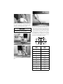
R
Operating and
Maintenance
Instructions
Manual
HCT908
Variable Speed
Hole-Cutting Tool
• Before operating or servicing the HCT908 Hole-Cutting Tool, read all
instructions in this manual and all warning labels on the tool.
• Always wear safety glasses, hardhat, foot protection, and hearing
protection.
• Save this operating and maintenance manual.
Failure to follow instructions and warnings can result in serious personal
injury, property damage, and/or product damage.
If you need additional copies of any literature, or if you have any questions about the safe operation of this tool,
contact Victaulic Tool Company, 1326 Tatamy Road, Easton, PA 18042, Phone: 610-559-3300.
Victaulic® Tool Company • 1326 Tatamy Road • Easton, PA 18045 • 1-800-PICK VIC • FAX: 610-250-7065
® Registered Trademark of Victaulic
© Copyright 2000 Victaulic
Printed in U.S.A.
HCT908
INDEX
Hazard Identification. . . . . . . . . . . . . . . . .2
Operator Safety Instructions . . . . . . . . . .3
Introduction . . . . . . . . . . . . . . . . . . . . . . . .4
Installing the Hole Saw onto the
Arbor Assembly. . . . . . . . . . . . . . . . . . . . .6
Tool Setup and Operation . . . . . . . . . . . . .6
Removing the Hole Saw from the
Arbor Assembly. . . . . . . . . . . . . . . . . . . . .9
Receiving Tool . . . . . . . . . . . . . . . . . . . . . .4
Maintenance . . . . . . . . . . . . . . . . . . . . . .10
Tool Nomenclature . . . . . . . . . . . . . . . . . .4
Accessories . . . . . . . . . . . . . . . . . . . . . . .11
Power Requirements. . . . . . . . . . . . . . . . .5
Troubleshooting. . . . . . . . . . . . . . . . . . . .12
HAZARD IDENTIFICATION
Definitions for identifying the various hazard levels are provided below.
This safety alert symbol indicates important safety messages. When you see this symbol,
be alert to the possibility of personal injury. Carefully read and fully understand the
message that follows.
The use of the word “DANGER” identifies an
immediate hazard with a likelihood of death or serious
personal
injury
if
instructions,
including
recommended precautions, are not followed.
NOTICE
The use of the word “NOTICE” identifies special
instructions that are important but not related to
hazards.
2
The use of the word “WARNING” identifies the
presence of hazards or unsafe practices that could
result in death or serious personal injury if
instructions, including recommended precautions, are
not followed.
HCT908
OPERATOR SAFETY INSTRUCTIONS
The HCT-908 is designed only for cutting holes in steel and stainless steel pipe. Using this tool
requires dexterity and mechanical skills, as well as sound safety habits. Although this tool is manufactured for safe, dependable operation, it is impossible to anticipate those combinations of circumstances that could result in an accident. The following instructions are recommended for safe
operation of this tool. The operator is cautioned to always practice “safety first” during each phase of
use, including setup and maintenance.
1. Read this manual before operating or servicing this tool. Become familiar with the tool’s
operations, applications, and limitations. Be particularly aware of its specific hazards. Store this manual
in a clean area where it is always readily available. Additional copies of this manual are available upon
request by calling or writing to the Victaulic Tool Company.
2. Avoid using the tool in dangerous environments. Do not expose the tools to rain, and do not use
the tools in damp or wet locations. Do not cut holes into pressurized pipe or pipe that is filled with water,
other fluid, or compressed gas. Keep the work area well lit.
3. Do not operate tools in gaseous or explosive environments. The motors in these tools produce
a normal spark, which could ignite fumes.
4. Ground all tools to protect the operator from electric shock.
5. Inspect the equipment. Before starting the tool, check the moveable parts for any obstructions. Make
sure that the tool’s parts are installed and secured properly.
6. Wear proper apparel. Do not wear loose clothing or jewelry, and keep long hair tied back.
7. Wear protective items when working with tools. Always wear safety glasses, hardhat, foot
protection, and hearing protection. A face or dust mask may be necessary if the cutting operation
produces fine particles.
8. Stay alert. Do not operate the tool if you are drowsy from medication or fatigue. Avoid horseplay around
the equipment.
9. Keep visitors away from the immediate work area. All visitors should be kept a safe distance from
the equipment at all times.
10. Secure work. Use clamps or a vise to hold work.
11. Do not overreach. Maintain proper footing and balance at all times.
12. Remove adjustment keys and wrenches from the tool. Always check to make sure adjustment
keys and wrenches are removed from the tool before operation.
13. Keep work areas clean. Keep the work area around the tool clear of obstructions that could limit the
movement of the operator. Clean up all oil and coolant spills. Remove shavings from the tool to maintain
proper operation.
14. Avoid accidental starting. Do not carry the plugged-in tool with your finger on the trigger.
15. Use proper extension cords for outdoor use. When using the tool outdoors, use only extension
cords marked suitable for outdoor use.
16. Do not force the tool. Do not force a smaller tool or attachment to do the job of a heavy-duty tool.
17. Do not abuse the power cord. Never carry the tool by the cord or yank it out of the receptacle. Keep
the cord away from heat, oil, and sharp objects.
18. Maintain tools with care. Keep tools sharp and clean at all times to ensure the best and safest
performance. Follow the instructions for lubricating and changing accessories.
19. Disconnect tools when not in use. Always disconnect tools when not in use; before servicing; when
changing accessories, such as blades, arbors, and chucks; and before removing the coupon from the hole
saw.
20. Store idle tools. When tools are not in use, store them in a dry, secure place.
21. Disconnect power cord before servicing the tool. Only authorized personnel should attempt to
change hole saws and perform maintenance on the tools. Always disconnect the power cord before
servicing or making any adjustments.
22. Use only Victaulic replacement parts and accessories. Use of any other parts may result in
improper operation and hazardous situations.
3
HCT908
NOTICE
Drawings and/or pictures in this manual may be exaggerated for clarity.
INTRODUCTION
The Victaulic HCT908 Variable Speed Hole-Cutting Tool is specifically designed to cut holes in steel
and stainless steel pipe for branch connections using Victaulic Hole Cut Products. This tool is not
designed for use on cast iron or PVC pipe. The HCT908 is suitable for 1¹⁄₄ - 8-inch (42,4 - 219,1-mm)
pipe sizes and can cut up to 4¹⁄₂-inch (115-mm) hole sizes.
RECEIVING TOOL
Upon receipt of the tool, check to make sure all necessary parts are included. If the shipping
container does not contain the correct components, contact Victaulic Tool Company. NOTE: If the
tool is rented, save the shipping container for return shipment.
Quantity
Description
1
Drill Motor Assembly with Chuck Key
1
Extra Pilot Drill with Coupon Saver
1
Arbor Assembly
1
Coupon Removal Tool
2
Instruction Manuals
1
Shipping Container
NOTE: Hole saws must be ordered separately.
Permanent carrying case is available and can be ordered separately.
TOOL NOMENCLATURE
Speed Control Dial
(on topside of Drill Motor Handle)
Feeder Knob
Drill Motor Handle
Drill Motor
Power Cord
Bearing
Feeder Rod
Trigger
Chuck Key
(attached to
power cord)
Vise
Handle
Chuck
Base
Coupon
Removal Tool
4
Chain
Slot
Arbor
Assembly
Chain
HCT908
POWER REQUIREMENTS
• To reduce the risk of electric shock, make sure the electrical source is properly grounded, and
follow all instructions carefully.
• Before performing any maintenance on the tool, disconnect it from the electrical source.
• Always unplug tool after each use.
Failure to follow these instructions could result in death or serious personal injury.
The tool is equipped with a three-prong plug and must be plugged into a grounded, single-phase
electrical receptacle (Figure A below). If an adapter is used to accommodate the three-prong plug,
the adapter’s wire must be attached to a known ground (refer to Figures A and B and power supply
chart below). Never remove the third prong.
➥
ADAPTER
➥
➥
➥
GROUNDING
PRONG IS
LONGEST OF
THE 3 PRONGS
GROUNDED
OUTLET BOX
Figure A
METAL
SCREW
➥
GROUNDED
OUTLET BOX
➥
Figure B
GROUNDING
MEANS
Figure C
NOTICE
• The tool is equipped with a UL Listed three-conductor cord and three-prong grounding type plug to fit the proper,
grounding type receptacle. The green (or green and yellow) conductor in the cord is the grounding wire. Never
connect the green (or green and yellow) wire to a live terminal.
Model
volts/(amps)
120
Power Supply
Requirements
120 VAC, 15 amp, 50/60 cycle power supply
(7)
EXTENSION CORD REQUIREMENTS
FOR ELECTRICALLY-POWERED TOOLS
It is important to use the proper extension cord size (e.g. conductor-sized American Wire Gauge/circular mils) when pre-wired outlets are not available. Cord size selection is based upon tool rating
(volts/amps) and cord length (feet/meters). Use of cord size thinner than required will cause a significant voltage drop at the tool while it is operating. The voltage drop may cause damage to the tool
and can result in failure of the tool to operate properly. Use of a heavier cord size than required is
acceptable.
The chart below contains the required cord sizes for cord lengths up to and including 100 feet (30
meters). Avoid using cords beyond 100 feet (30 meters) in length.
Recommended Extension Cord Conductor Size at Various Cord Lengths
Circuit Rating volts
(amps)
Cord Length feet
(meters)
Conductor Size American Wire Gauge
(circular mils)
25
12
(8)
(6 530)
120
50
12
(15)
(15)
(6 530)
100
10
(30)
(10 380)
5
HCT908
INSTALLING THE HOLE
SAW ONTO THE ARBOR
ASSEMBLY
TOOL SETUP AND
OPERATION
• DO NOT plug the tool into the electrical source until
instructed.
Failure to follow this instruction could result in serious
personal injury.
1. Ensure that the pipe is secured before
attempting to use this hole-cutting tool.
1. Depending on the type of arbor assembly
included with the tool, thread or push the locking ring of the arbor assembly back as far as it
will go.
2. Locate the center of the hole to be cut on
the pipe run. Mark this center point clearly
with a punch.
NOTICE
2. Thread the hole saw onto the arbor assembly just enough to line up the holes in the top of
the hole saw with the drive pins on the arbor
assembly. If the pins do not line up with the
holes, back off the hole saw just enough to line
up the holes with the drive pins
3. Thread or push the locking ring of the arbor
assembly all the way down, making sure the
pins of the arbor assembly engage the holes in
the top of the hole saw. Make sure the hole saw
is flush with the arbor assembly and that the
hole saw is installed firmly onto the arbor
assembly.
6
• When selecting the hole location, take into account
the width of the product you are installing. Ensure
that it will fit and not interfere with couplings or
grooves. Additionally, allow room on the pipe to
mount the hole-cutting tool.
3. Place the hole-cutting tool onto the pipe.
Hook the chain around the pipe and insert it
into the chain slot on the side of the tool’s base.
Leave the chain loose enough to allow base
movement.
HCT908
4. Raise the drill motor to its highest position
by rotating the feeder knob counterclockwise.
8. Using the vise handle, tighten the chain
around the pipe to secure the hole-cutting tool.
• To reduce the risk of electric
shock, check the electrical
source for proper grounding,
and follow the instructions
below.
Failure to follow these instructions could result in
death or serious personal injury.
5. Take the hex-shaped end of the arbor
assembly, and insert it into the chuck of the
drill’s motor.
Switch –
shown in
forward
position
Trigger
9. Check the switch on the underside of the
drill motor’s handle. Make sure the switch is in
the “forward” position, as shown above.
6. Support the arbor assembly, while tightening the chuck securely with the chuck key provided.
7. Align the hole saw’s drill bit with the center
punch mark.
10a. Install cord by aligning connector’s keyways. Push connector in as far as it will go.
Turn the cord’s nut ¹⁄₄-turn to the right to lock
the cord in place.
7
HCT908
10b. Plug the drill motor’s cord into an appropriate outlet or extension cord (refer to “Power
Requirements” section on page 5).
• NEVER use the HCT908 Hole-Cutting Tool on
applications where spark hazards exist or contact
with water can occur.
Failure to follow this instruction could result in serious
personal injury and product damage.
Speed
Control
Dial
11. Set the speed control dial (on the topside
of the drill motor’s handle) for the correct application. Refer to the chart below.
Hole Saw
Size
inches
(mm)
1
(26 mm)
1¹⁄₄
(32 mm)
1¹⁄₂
(38 mm)
1³⁄₄
(45 mm)
2
(51 mm)
2¹⁄₂
(64 mm)
2³⁄₄
(70 mm)
3¹⁄₂*
(89 mm)
4¹⁄₂*
(115 mm)
Speed Control
Setting
for Steel Pipe
Speed Control
Setting for
Stainless Steel
Pipe
8
3 to 4
8
3 to 4
8
3 to 4
8
3 to 4
8
3 to 4
8
2 to 3
8
2 to 3
3 to 4
3 to 4
3 to 4
3 to 4
NOTE: All of the settings shown to the right are based on using Milwaukee^ 4/6 Super-Tough° BI Metal Hole Saws or Victaulic Hole Saws.
* Milwaukee 4/6 Super-Tough Bi-Metal Hole Saws or Victaulic Hole
Saws MUST be used for 3¹⁄₂-inch (89 mm) and 4¹⁄₂-inch (115 mm)
sizes.
^Milwaukee is a registered trademark of Milwaukee Electric Tool Corporation.
°Super-Tough is a registered trademark of Milwaukee Electric Tool Corporation.
8
12. Depress the trigger on the underside of
the drill motor’s handle, and feed the hole saw
by turning the feeder knob clockwise. Feed the
saw into the cut at a moderate rate to maintain
good cutting action. DO NOT feed the saw too
fast, since it can cause the motor to stall. If difficulties occur during the cutting operation,
refer to the “Troubleshooting” section on page
12.
13. After completing the cut, remove your finger from the trigger, and retract the hole saw
by turning the feeder knob counterclockwise.
NOTICE
• To extend hole saw life, apply steel pipe thread
cutting oil to the hole while you are performing the
cutting operation.
• Avoid touching the coupon with
your bare hands. Coupons can be
very hot and sharp.
Failure to follow this instruction
could result in serious personal
injury.
HCT908
14. Unplug the tool from the electrical source.
Remove the coupon from the hole saw by using
the coupon removal tool, as shown above. Use
care not to damage the wire wound into the
drill. Remove any chips from the drill.
NOTICE
• If the coupon fell out of the tool and into the pipe,
remove the coupon from inside the pipe.
17. Brush away shavings from around the hole
so that the hole-cut product’s gasket can seal
properly on the pipe. Use a file, if necessary, to
remove burrs or scratches from the gasket sealing area. The pipe surface within ⁵⁄₈" (16 mm)
of the hole must be clean, smooth, and free
from indentations that might affect gasket
sealing. The pipe around the entire circumference within the “A” dimension (refer to chart
and illustration above) must be free of any dirt
or projections that might prevent the hole-cut
product from seating fully on the pipe
A
⁵⁄₈"
(16 mm)
15. Support the tool. Loosen the vise handle.
16. Continue to support the tool. Unhook the
chain from the slot. Remove the tool from the
pipe.
Branch Size
inches
(mm)
“A” Dimension
inches
(mm)
¹⁄₂
3 ¹⁄₂
(21,3)
(90)
³⁄₄
3 ¹⁄₂
(26,9)
(90)
1
3 ¹⁄₂
(33,7)
(90)
1 ¹⁄₄
4
(42,4)
(100)
1 ¹⁄₂
4
(48,3)
(100)
2
4¹⁄₂
(60,3)
(115)
2 ¹⁄₂
4³⁄₄
(73,0)
(120)
76,1 mm
4³⁄₄
(120)
3
5¹⁄₂
(88,9)
(140)
4
6¹⁄₂
(114,3)
(165)
9
HCT908
LUBRICATION
REMOVING THE HOLE
SAW FROM THE ARBOR
ASSEMBLY
The HCT908 Hole-Cutting Tool is lubricated at
the factory. However, periodic lubrication of
the following parts will maintain smooth and
proper operation of the tool.
• Always unplug the tool from the electrical source
before removing the hole saw from the arbor
assembly.
Failure to follow this instruction could result in serious
personal injury.
1. Lubricate the feeder rod with light oil.
1. Remove the arbor assembly from the drill by
using the chuck key provided.
2. Lubricate the bearing with light oil.
ADJUSTING THE GIB
2. Depending on the type of arbor assembly
included with the tool, pull or thread the locking ring all the way up, making sure the pins in
the arbor assembly are completely free from the
hole saw. Unscrew the hole saw from the arbor
assembly and remove.
MAINTENANCE
• Before performing any maintenance on the tool,
disconnect it from the electrical source.
Failure to follow this instruction could result in serious
personal injury.
10
After many uses, play may develop at the gib,
allowing excessive side-to-side movement of
the drill motor assembly. This play is easily corrected by using the screw adjustment provided.
1. Loosen the lock nuts, and adjust the screws
to take up any slack (refer to the photo above).
2. Re-tighten the lock nuts while holding the
screws in place. Check the side-to-side movement in the assembly. Run the assembly up
and down by using the feeder knob, and check
for excessive drag. When properly adjusted,
very little side-to-side motion will occur, and
very little drag will be felt when rotating the
feeder knob.
HCT908
ARBOR ASSEMBLY FOR
1¹⁄₄-INCH (32-mm) OR LARGER
DIAMETER HOLE SAWS
ACCESSORIES
ARBOR ASSEMBLY FOR 1-INCH
(26-mm) DIAMETER HOLE SAW
405
406 407 408 409
411 414 416 417
412
413
415
404
402
402
Item
No.
Part No.
450
R-450-900-HCT
Qty.
Description
Ref. Arbor Assembly
Item
No.
Part No.
400
R-400-900-HCT
Qty.
Description
Ref. Arbor Assembly1
402
R-402-900-HCT
1
Coupon-Retaining Drill Bit
402
R-402-900-HCT
1
Coupon-Retaining Drill Bit
412
N-M14-000-007
1
Arbor
404
N-S90-050-010
1
Nyloc Half Dog Set Screw
415
N-S90-050-004
1
Nyloc Half Dog Set Screw
405
N-M14-000-025
1
Arbor
413
N-M18-000-011
*
Hole Saw 1" (26 mm)
406
N-M18-000-016
*
Hole Saw 1¹⁄₄" (32 mm)
407
N-M18-000-021
*
Hole Saw 1¹⁄₂" (38 mm)
408
N-M18-000-026
*
Hole Saw 1³⁄₄" (45 mm)
409
N-M18-000-031
*
Hole Saw 2" (51 mm)
411
N-M18-000-037
*
Hole Saw 2¹⁄₂" (64 mm)
414
N-M18-000-040
*
Hole Saw 2³⁄₄" (70 mm)
416
N-M18-000-047
*
Hole Saw 3¹⁄₂" (89 mm)
417
N-M18-000-050
*
Hole Saw 4¹⁄₂" (115 mm)
*Hole saws must be ordered separately
*Hole saws must be ordered separately.
1
Arbor assembly is supplied with the tool.
11
HCT908
TROUBLESHOOTING
PROBLEM
POSSIBLE CAUSE
SOLUTION
Base will not fully tighten
onto the pipe.
Vise handle has run out of threads.
Loosen vise handle and position one link tighter on
chain slot. Re-tighten vise handle.
Motor will not run.
1) Tool is not plugged in.
2) A fuse is blown, or the circuit
breaker is off or tripped.
3) Motor trigger switch is defective.
4) Plug is not making good contact
with the receptacle.
5) Tool cord is damaged.
1) Plug the tool into the proper voltage outlet or
extension cord.
2) Replace the power supply fuse, or reset the
breaker.
3) Replace the motor trigger switch.
4) Inspect the connection and make repairs, as
necessary.
5) Replace the tool’s cord.
Pilot drill will not cut.
1) Drill motor is running in reverse.
2) Pilot drill is not tight in the arbor.
3) Pilot drill is dull.
1) Move the motor switch to the forward position.
2) Tighten the arbor’s set screw. Make sure it
engages the pilot drill’s flats.
3) Replace the pilot drill.
Hole saw blade will not
cut.
1) Drill motor is running in reverse.
2) Hole saw blade is dull.
3) One or more teeth have been
broken off the hole saw blade.
4) Pipe has a hard spot or a hard weld
seam.
5) Chips are stuck in the cut.
1) Move the motor switch to the forward position.
2) Replace the hole saw blade.
3) Replace the hole saw blade. Inspect the cut to see
if teeth are lodged in the pipe. Remove lodged
teeth with a center punch or a small chisel (wear
eye protection).
4) Use a sharp hole saw blade and generously
lubricate the cut with thread-cutting oil. Cut the
hole slowly.
5) Remove chips from the hole saw’s teeth and the
cut.
Excessive torque is
required to rotate the
feeder knob.
1) Move the motor switch to the forward position.
1) Drill motor is running in reverse.
2) There is a lack of lubrication on the 2) Lubricate the feeder rod according to the
instructions in the “Maintenance” section of this
feeder rod.
manual.
3) The gib is too tight.
3) Re-adjust the gib according to the instructions in
the “Maintenance” section of this manual.
Drill motor gets very hot.
1) Holes are being cut too fast.
2) Hole saw blade is dull.
3) An undersized or too long of an
extension cord is being used.
1) Feed the hole saw into the cut at a moderate rate,
and do not bog down the motor.
2) Replace the hole saw blade.
3) Replace the extension cord with one of the proper
size and length (refer to “Power Requirements”
section in this manual).
Excessive side-to-side
play is occurring.
Gib is out of adjustment.
Adjust the gib, according to the instructions in the
“Maintenance” section of this manual.
Pilot drill does not retain
the coupon.
Coupon retaining drill bit is damaged.
Replace the pilot drill.
Hole saw life is short.
Speed control dial is set too high.
Set the speed control dial to the recommended
setting listed in this manual.
Victaulic® Factory Representatives and Distributor Stocks Worldwide
Victaulic reserves the right to change product specifications, designs and standard equipment
without notice and without obligation.
TM-HCT908
12
3022 Rev.B
9/01
RM00908000