1
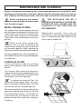
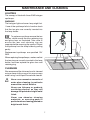
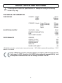
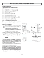
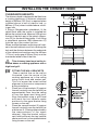
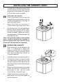
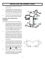
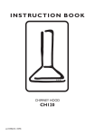
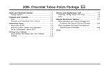
ELTSHDC110SG/
Users Guide
&
Installation Instructions
CONTENTS
IMPORTANT SAFETY INFORMATION
Installation
Page
2
Child Safety
2
Maintenance and service
3
Cooker Hood Controls
To Operate
4
5
Recirculation
5
Extraction
5
Metal Grease Filters
6
Charcoal Filter
6
Lighting
7
Cleaning
7
INSTALLATION INSTRUCTIONS
Technical Information
8
ELECTRICAL CONNECTION
Elecrical Requirements
9
Electrical Connection
9
YOUR APPLIANCE
OPERATING INSTRUCTIONS
MAINTENANCE AND CLEANING
INSTALLING THE CHIMNEY HOOD
1
Components
10
Installation Requirements
10
Clearance Heights
11
Fitting the Wall Brackets
11
Drilling the Holes 1
12
Fixing the Canopy
12
Ducting
13
Recirculation
13
Fitting the Recirculation Ducting
13
Fitting the Telescopic Chimney
14
IMPORTANT SAFETY INFORMATION
These warnings are provided in the interests of safety. Ensure that you understand
them all before installing or using this appliance. Your safety is of paramount importance.
If you are unsure about the meaning of any of these warnings contact the Helpline.
• INSTALLATION
•
Any installation work must be
undertaken by a qualified electrician or
a competent person.
•
This hood must be installed in
accordance with the installation
instructions and all measurements
must be adhered to.
•
If the cooker hood is installed for use
above a gas appliance then the
provision for ventilation must be in
accordance with the latest edition of
the Gas Safety Codes of Practice and
the Gas Safety (Installation & Use)
Regulations, the Building Regulations
issued by the Department of the
Environment, the Building Standards
(Scotland) (Consolidated) Regulations
issued by the Scottish Development
Department.
•
It is dangerous to alter the
specifications or modify this product in
any way.
•
When installed between adjoining wall
cabinets the wall cabinets must not
overhang the hob.
If the room where the cooker hood is to
be used contains a fuel burning appliance
such as a central heating boiler then its
flue must be of the room sealed or
balanced flue type.
•
If other types of flue or appliances are
fitted ensure that there is an adequate
supply of air to the room.
•
The ducting system for this appliance
must not be connected to any existing
ventilation system that is being used for
any other purpose.
•
Do not install above a cooker with a highlevel grill.
• CHILD SAFETY
•
This appliance is designed to be operated
by adults. Children should not be allowed
to tamper with the appliance.
• DURING USE
The fan motor of this cooker hood
incorporates a cut-out device which will
operate if the cooker hood is installed
below the minimum height
recommended under the section
‘Clearance Height’, or if the motor
becomes overheated. If the cut-out
device is activated, switch off the fan
motor and allow the cooker hood to
cool. The cut-out device will reset itself
when the fan motor has cooled
significantly.
•
•
2
•
This product is for domestic use only.
•
Never leave frying pans unattended during
use as overheated fats and oils might
catch fire.
•
Never do flambé cooking under this
cooker hood.
•
Do not leave naked flames under the
cooker hood.
IMPORTANT SAFETY INFORMATION
• MAINTENANCE AND SERVICE
•
This appliance can be a hazard if the
grease filters and charcoal filters are not
cleaned and replaced as recommended.
•
Always insist on genuine RANGEmaster
spare parts.
•
The halogen light and cover lamp might
hot.
•
Under no circumstances should you
attempt to repair the appliance yourself.
Repairs carried out by inexperienced
persons may cause injury or more
serious malfunction. In the event of your
chimney hood requiring service contact:
RANGEmaster Helpline: 0845 603
5312, or
Consumer Services: 0870 789 5107
3
YOUR APPLIANCE
OPERATING INSTRUCTIONS
The chimney hood is designed to extract
unpleasant odours from the kitchen, it will
not extract steam. The appliance can be
installed to recirculate or extract
contaminated air.
BUTTON V1 - Turns the fan On and Off at
the low speed setting. This is
an ideal speed when cooking
for long periods as the
continuous flow of air is
particularly quiet.
COOKER HOOD CONTROLS
BUTTON V2 - Second speed, suitable for
most normal operating
conditions. This speed gives an
excellent ratio between treated
air when the hood is recirculated
and the level of noise.
The chimney hood functions are controlled
by four push buttons located centrally on
the front of the canopy.
L
0-1
V1
BUTTON L
MID
V2
MAX
BUTTON V3 - Third speed, suitable for
removing strong odours when
frying or simmering for long
periods.
0-1
V3
- Turns the worktop lighting
On and Off.
4
OPERATING INSTRUCTIONS
TO OPERATE
Select the required fan speed and light if
required.
To obtain the best performance when cooking
it is advisable to switch the chimney hood on
for a few minutes before you start cooking
and leave it running for about 15 minutes after
finishing.
RECIRCULATION
In the recirculation mode contaminated air
enters the chimney hood through the grease
filter cassettes. The air is cleaned as it passes
through the (optional) charcoal filter and is
passed out through grilles in either side of the
chimney stack into the kitchen.
EXTRACTION
In the extraction mode contaminated air
enters the chimney hood through the grease
filter cassettes and is passed out through
ducting into the atmosphere.
When used in the ducting mode
the charcoal filter is not required.
Never do flambé cooking under
this chimney hood.
When using a gas hob under this
chimney hood never leave the
burners uncovered while the
hood is in use or when the pans
have been removed.
The grease filters and the
charcoal filter should be cleaned
and replaced as recommended or
more frequently if the hood is
used consistently over 4 hours
per day.
5
MAINTENANCE AND CLEANING
Regular maintenance and cleaning will ensure good performance and reliability, while
extending the working life of the hood. Special attention should be paid to the grease
filter cassettes and the charcoal filter when the hood is used in the recirculation mode.
Before carrying out any maintenance or cleaning isolate the cooker hood
from the mains supply.
METAL GREASE FILTERS
THIS APPLIANCE CAN BE A
POSSIBLE FIRE HAZARD IF THE GREASE
FILTERS ARE NOT CLEANED AND THE
CHARCOAL FILTERS REPLACED AS
RECOMMENDED.
The grease filters absorb grease and dust
during cooking to help keep the chimney hood
clean inside, and should be cleaned every
month with normal usage or more frequently
if the hood is used consistently over 4 hours
per day.
Replacement charcoal filters may be
purchased by returning the enclosed order
form, or by telephoning 01803 296155 if you
wish to pay by credit card.
Remove the metal grease filter
cassettes one at a time, by pressing the
release catch towards the rear of the hood
as illustrated opposite. When replacing the
filters ensure that the handle faces forwards.
The metal grease filters can be washed in a
dishwasher or by hand using a mild detergent
or liquid soap.
CHARCOAL FILTER
In the recirculation mode the activated
charcoal filter absorbs smells and unwanted
odours.
The charcoal filter cannot be cleaned or
regenerated and must be replaced every four
months, or more frequently if the hood is used
consistently over 4 hours per day.
To replace the charcoal filter, first
remove the metal grease filters and press
against the plastic retaining clips to remove
the charcoal filter as illustrated opposite.
We recommend that you wear rubber gloves
when removing the charcoal filter as the filter
will be saturated in grease. Put the filter into
a polythene bag or container so that the
grease and dirt cannot spill onto clothing of
furnishing.
6
MAINTENANCE AND CLEANING
LIGHTING
The canopy is fitted with three 20W halogen
spotlamps.
WARNING!
The halogen light and cover lamp might hot.
If one of the spotlamps fails to function check
that the two pins are correctly inserted into
the lamp holder.
To replace a spotlamp remove the two
screws, which secure the lens retaining ring
and glass lens as illustrated. Take care to
ensure the lens and retaining ring are
supported while removing the screws. Extract
the spotlamp from the lamp holder by pulling
gently.
Replacement spotlamps are specified 12V
20W.
When replacing the spotlamps, make sure that
the two pins are correctly inserted in the lamp
holder, and then replace the glass lens and
retaining ring.
CLEANING
We recommend the chimney hood is cleaned
using a damp cloth wrung out in warm soapy
water using a mild liquid household cleaner.
Never use excessive amounts of
water when cleaning, in particular
around the control buttons.
Never use thinners or products
containing alcohol, as they will
damage the painted or bright metal
finish.
Never use abrasive cleaning
materials, or scouring pads in
particular when cleaning painted or
bright metal finish.
7
INSTALLATION INSTRUCTIONS
It is dangerous to alter the specifications or attempt to modify this chimney
hood in any way.
TECHNICAL INFORMATION
DIMENSIONS
CANOPY: Height
Width
Depth
CHIMNEY: Height - Upper Chimney
Lower Chimney
Width
Depth
ELECTRICAL SUPPLY
VOLTAGE: ~50Hz
POWER CONSUMPTION:
FAN:
SPOTLAMPS: 3x20W
PERFORMANCE
SPEEDS
CAPACITY m3/h*
CAPACIITY m3/h**
PRESSURE PA
INPUT W
NOISE LEVEL dBA***
70mm
1098mm
500mm
215mm
740mm
300mm
260mm
230V
265W
205W
60W
3
550
660
320
205
68
*IEC 61591 method for cooker hoods in evacuation mode - ** IEC 61591 method with free delivery - ***IEC
60704-2-13 method
Note: CE Marking certifies that this appliance complies with the requirements
laid down in EEC directive 89:336 (Electromagnetic compatibility) and
subsequent modifications and Low Voltage directive 72/23/E.
8
ELECTRICAL CONNECTION
THIS APPLIANCE MUST BE EARTHED
ELECTRICAL REQUIREMENTS
Any permanent electrical installation must
comply with the latest I.E.E. Regulations and
local Electricity Board regulations. For your
own safety this should be undertaken by a
qualified electrician e.g. your local Electricity
Board, or a contractor who is on the roll of
the National Inspection Council for Electrical
Installation Contracting (NICEIC).
ELECTRICAL CONNECTION
Before connecting to the mains supply
ensure that the mains voltage corresponds
to the voltage on the rating plate inside the
cooker hood.
This appliance is fitted with a 3 core mains
cable and must be permanently connected
to the electricity supply via a double-pole
switch having 3mm minimum contact gap on
each pole. A Switched Fuse Connection Unit
to BS.1363 Part 4, fitted with a 3 Amp fuse, is
a recommended mains supply connection
accessory to ensure compliance with the
Safety Requirements applicable to fixed
wiring instructions.
This appliance conforms to BS.800:1988 and
EEC Directive No. 78 308 regarding
suppression of radio and television
interference.
9
INSTALLING THE CHIMNEY HOOD
COMPONENTS
The chimney hood comprises of the
following: No 1 150x120mm ducting spigot (A)
No 1 125x120mm ducting spigot (D)
No 1 Splashback (B) optional
No 1 Canopy (C)
No 2 Recirculation grilles (G)
No 1 Lower chimney stack (I)
No 1 Recirculation ducting (P)
No 2 Recirculation extension ducts (P1)
No 1 Recirculation spigot (R)
No 1 Upper chimney stack (S)
No 2 Chimney fixing brackets (2)
Please ensure when the appliance is fitted it
is easily accessible to an engineer in the
event of a breakdown.
All installations must comply with
local authorities requirements for
the discharge of exhaust air.
D
Incorrect installation may affect the
safety of this chimney hood.
INSTALLATION REQUIREMENTS
Before installation check the wall
to which the hood is to be fitted for
electric cables, gas and water
pipes.
This chimney hood is designed to be fixed to
any vertical surface over a cooking area, and
can be used in the extraction (ducted to the
outside) or recirculation mode.
The installation work must be undertaken by
a qualified and competent person.
RANGEMASTER Consumer Products
disclaims any responsibility for damage due
to incorrect installation of the chimney hood
or if the hood is not installed in compliance
with relevant regulations controlling this type
of installation.
10
INSTALLING THE CHIMNEY HOOD
CLEARANCE HEIGHTS
The chimney hood is designed to be fitted over
a cooking appliance. A minimum clearance
height of 650mm (251/2ins) is required when
installed above a built-in electric hob, or
685mm (27ins) when installed above a builtin gas hob.
If fitting a Rangemaster splashback, fit the
splash back after the cooker is installed but
before the cooker hood. Measure 328 up from
the top of the thick part of the splash (dimension ‘B’) for the hood fixing holes. If not fitting
a splashback measure 1000 (dimension ‘A’)
from the top of the cooker flue trim.
When installed between adjoining wall cabinets, the wall cabinets must not overhang the
hob and the distance between the underside
of the cabinet and worktop must be 450mm
(17½ins), and a gap of 50mm (2ins) must be
maintained either side of the hob.
This chimney hood must not be installed above a cooking appliance with a
high level grill.
1.
2.
3.
FITTING THE WALL BRACKETS
Draw a vertical line on the wall as
illustrated, from the centre of the
cooking appliance up to the ceiling
using a spirit level and marker pen.
This is to ensure the correct vertical
alignment of the various components
during installation.
Place one of the brackets (2) against
the wall, centrally over the vertical line
approximately 2mm from the ceiling
or from the upper most fixing point.
Align the bracket using a spirit level
and mark the two keyhole centre
positions for the upper bracket fixing
screws on the wall.
Place the second bracket (2) against
the wall, centrally over the vertical line
at distance X. (X being determined by
the measurement of the upper
chimney). Align the bracket using a
spirit level and mark the two keyhole
centre positions for the middle bracket
fixing screws on the wall.
11
INSTALLING THE CHIMNEY HOOD
4.
1.
Drill the holes for the fixing screws using
an 8mm masonry drill bit. Insert the rawl
plugs and fix the brackets (2) using the
4.2 x 44.4mm screws provided.
DRILLING THE HOLES 1
Draw a horizontal line through the
vertical 970mm up the wall from the top
of the cooking appliance, ensuring it is
level with a spirit level.
2.
Mark the centres for the holes 1,
116mm either side of the vertical line.
3.
Drill the two holes 1 for the fixing screws
using an 8mm masonry drill bit. Insert
the rawl plugs and the 4.2 x 44.4mm
screws provided. Tighten the screws,
leaving a space of 5-6mm between the
head and the wall.
Note: If the chimney hood is to be installed
onto a hollow construction plaster or
partition board wall then special fixing
screws will be required (not supplied).
FIXING THE CANOPY
1.
Before starting to fix the canopy to the
wall, it is necessary to adjust the
support brackets S1 by rotating the
adjustment screws clockwise about
half way through their length as
illustrated opposite.
2.
Hook the canopy C onto the two screws 1.
3.
To level the canopy on the wall rotate
the adjustment screws S1 until the
canopy is level and then tighten up the
wall fixing screws to secure the canopy
to the wall.
4.
Before fitting the chimney to the canopy
make the electrical connection as
described in the section titled
‘ELECTRICAL CONNECTION’.
5.
When the electrical connection has
been made, test the three speed fan
12
and the spotlams
INSTALLING THE CHIMNEY HOOD
DUCTING
The hood is more effective when used in the
extraction mode (ducted to the outside).
When used in the extraction mode ensure the
ducting spigot has been correctly fitted as
illustrated.
D
The ducting used must be ∅ 125
(5ins) or ∅150mm (6ins), flexible or
rigid and must be manufactured
from fire retardant material,
produced to BS.476 or DIN.4102B1. The choice should be made by
the installer. However, we
recommend flexible ducting should
only be used as an accessory as
rigid ducting will provide better
performance while reducing noise
levels.
The ducting flange D should be sleeved over
the spigot A when using 125mm (5ins)
ducting as the European ducting spigot is
∅120mm.
Ducting kits can be obtained from Kitchen
Specialist Distriutors, Builders Merchants and
DIY stores.
When the chimney hood is ducted to the
outside the charcoal filter must be removed.
RECIRCULATION
If you are using the hood in the recirculation
mode, ensure the charcoal filter is in position.
FITTING THE RECIRCULATION
DUCTING
1.
Connect the duct P to the round outlet
on top of the fan housing, which push
fits into position, by pressing it
downwards until it meets the fan
casing.
2.
Connect the spigot R on to the top of
the duct P, which push fit into position,
13
INSTALLING THE CHIMNEY HOOD
by pressing it downwards until the two
pieces meet.
3.
4.
Connect the two recirculation extension
ducting pipes P1 on to the outlets on
either side of the spigot R, which push
fit into position, by pressing them
horzontally until the two pieces meet.
7.2.1
12c
2.1
Do not fit the recirculation grilles until
after the chimney has been installed.
2
8b
FITTING THE TELESCOPIC
CHIMNEY
2.2
8a
The chimney stack consists of two sections.
1.
To fit the upper chimney section S, first
apply pressure to expand the two side
panels slightly to allow the chimney to
be fitted around the two brackets 2 as
illustrated opposite. Fix the chimney to
the two brackets 2 using four of the
screws provided with the fixing kit.
2.
To fit the lower chimney section I, first
apply pressure to expand the two side
panels slightly to allow the chimney to
be fitted around the upper chimney S
and the canopy C as illustrated
opposite. Fix the chimney to the canopy
C using two of the screws provided with
the fixing kit.
3.
To fit the two push-fit recirculation grilles
G, insert them one at a time into the
holes on either side of the chimney and
apply slight pressure until they snap
into position. Ensure the grilles are
fitted correctly with one arrow pointing
upwards
and one
forwards.
4.
When the hood is installed in the
recirculation mode, ensure the
recirculation grilles G, are properly
secured to the inside of the recirculation
ducting as illustrated opposite.
12c
14
Dir. 89/336/CEE
73/23/CEE
93/68/CEE
The symbol
on the product or on its packaging indicates that this product may not be treated as household waste. Instead it shall
be handed over to the applicable collection point for the recycling of electrical and electronic equipment. By ensuring this product is
disposed of correctly, you will help prevent potential negative consequences for the environment and human health, which could
otherwise be caused by inappropriate waste handling of this product. For more detailed information about recycling of this product,
please contact your local city office, your household waste disposal service or the shop where you purchased the product.
436001896_04 - 060210