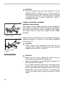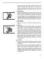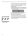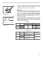
1
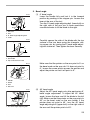
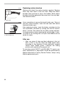
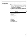
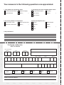
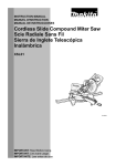
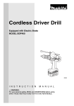
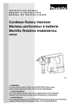
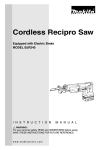
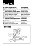
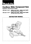
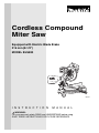
Cordless Compound
Miter Saw
Equipped with Electric Blade Brake
216 mm (8-1/2”)
MODEL BLS820
001764
I N S T R U C T I O N
M A N U A L
WARNING:
For your personal safety, READ and UNDERSTAND before using.
SAVE THESE INSTRUCTIONS FOR FUTURE REFERENCE.
SPECIFICATIONS
Blade diameter ........................................................................................... 216 mm (8-1/2”)
Hole (arbor) diameter ................................................................................. 15.88 mm (5/8”)
Max. Miter angle ......................................................................................Left 52°, Right 52°
Max. Bevel angle ......................................................................................................Left 45°
Max. Cutting capacities (H x W)
Bevel angle
Miter angle
0°
45° (left)
0°
61 mm x 122 mm
(2-3/8” x 4-13/16”)
45 mm x 122 mm
(1-3/4” x 4-13/16”)
45° (left and right)
61 mm x 85 mm
(2-3/8” x 3-3/8”)
45 mm x 85 mm
(1-3/4” x 3-3/8”)
(Note)
The max. Cutting capacities may vary according to workpiece, blade and/or charging
condition.
No load speed (RPM) .......................................................................................... 2,300/min.
Dimensions (L x W x H) ..................528 mm x 430 mm x 486 mm (20-3/4” x 17” x 19-1/8”)
Net weight ................................................................................................. 10.1 kg (22.3 lbs)
Battery Charger
DC24SA
DC24SA
Input
A.C. only 50 Hz - 60 Hz
Output
D.C. 7.2 V - 24 V
Battery Cartridge
BH2420
BH2433
Voltage
Charging time
BH2420
BH2433
55 min.
90 min.
24 V
30 min.
60 min.
• Manufacturer reserves the right to change specifications without notice.
• Specifications may differ from country to country.
2
For Your Own Safety Read Instruction Manual
Before Operating Tool
Save it for future reference
USA005-1
GENERAL SAFETY PRECAUTIONS
(For All TOOIS)
1. KNOW YOUR POWER TOOL. Read the
owner’s manual carefully. Learn the tool’s
applications and limitations, as well as the
specific potential hazards peculiar to it.
2. KEEP GUARDS IN PLACE and in working
order.
3. REMOVE
ADJUSTING
KEYS
AND
WRENCHES. Form habit of checking to
see that keys and adjusting wrenches are
removed from tool before turning it on.
4. KEEP WORK AREA CLEAN. Cluttered
areas and benches invite accidents.
5. DON’T USE IN DANGEROUS ENVIRONMENT. Don’t use power tools in damp or
wet locations, or expose them to rain.
Keep work area well lighted. Don’t use
tool in presence of flammable liquids or
gases.
6. KEEP CHILDREN AWAY. All visitors
should be kept safe distance from work
area.
7. MAKE WORKSHOP KID PROOF with padlocks, master switches, or by removing
starter keys.
8. DON’T FORCE TOOL. It will do the job better and safer at the rate for which it was
designed.
9. USE RIGHT TOOL. Don’t force tool or
attachment to do a job for which it was not
designed.
10. WEAR PROPER APPAREL. Do not wear
loose clothing, gloves, neckties, rings,
bracelets, or other jewelry which may get
caught in moving parts. Nonslip footwear
is recommended. Wear protective hair
covering to contain long hair.
11. ALWAYS USE SAFETY GLASSES. Also
use face or dust mask if cutting operation
is dusty. Everyday eyeglasses only have
impact resistant lenses, they are NOT
safety glasses.
12. SECURE WORK. Use clamps or a vise to
hold work when practical. It’s safer than
using your hand and it frees both hands
to operate tool.
13. DON’T OVERREACH. Keep proper footing
and balance at all times.
14. MAINTAIN TOOLS WITH CARE. Keep tools
sharp and clean for best and safest performance. Follow instructions for lubricating
and changing accessories.
15. DISCONNECT BATTERY FROM TOOL
before servicing; when changing accessories such as blades, bits, cutters, and
the like.
16. REDUCE THE RISK OF UNINTENTIONAL
STARTING. Make sure switch is in off
position before inserting battery.
17. USE RECOMMENDED ACCESSORIES.
Consult the owner’s manual for recommended accessories. The use of improper
accessories may cause risk of injury to
persons.
3
18. NEVER STAND ON TOOL. Serious injury
could occur if the tool is tipped or if the
cutting tool is unintentionally contacted.
affect its operation. A guard or other part
that is damaged should be properly
repaired or replaced.
19. CHECK DAMAGED PARTS. Before further
use of the tool, a guard or other part that
is damaged should be carefully checked
to determine that it will operate properly
and perform its intended function - check
for alignment of moving parts, binding of
moving parts, breakage of parts, mounting, and any other conditions that may
20. DIRECTION OF FEED. Feed work into a
blade or cutter against the direction of
rotation of the blade or cutter only.
21. NEVER LEAVE TOOL RUNNING UNATTENDED. TURN POWER OFF. Don’t leave
tool until it comes to a complete stop.
ADDITIONAL SAFETY RULES
USB034-2
DO NOT let comfort or familiarity with product (gained from
repeated use) replace strict adherence to miter saw safety
rules. If you use this tool unsafely or incorrectly, you can suffer
serious personal injury.
1. Wear eye protection.
2. Keep hands out of path of saw blade.
Avoid contact with any coasting blade. It
can still cause severe injury.
3. Do not operate saw without guards in
place. Check blade guard for proper closing before each use. Do not operate saw if
blade guard does not move freely and
close instantly. Never clamp or tie the
blade guard into the open position.
4. Do not perform any operation freehand.
The workpiece must be secured firmly
against the turn base and guide fence
with a vise during all operations. Never
use your hand to secure the workpiece.
5. Never reach around saw blade.
6. Turn off tool and wait for saw blade to
stop before moving workpiece or changing settings.
7. Remove battery from tool before changing blade or servicing.
4
8. Always secure all moving portions before
carrying the tool.
9. Be aware that this tool is always in an
operating condition, because it does not
have to be plugged into an electrical outlet.
10. Do not use the tool in the presence of
flammable liquids or gases.
11. Check the blade carefully for cracks or
damage
before
operation.
Replace
cracked or damaged blade immediately.
Gum and wood pitch hardened on blades
slows saw and increases potential for kickback. Keep blade clean by first removing it
from tool, then cleaning it with gum and pitch
remover, hot water or kerosene. Never use
gasoline to clean blade.
12. Use only flanges specified for this tool.
13. Be careful not to damage the arbor,
flanges (especially the installing surface)
or bolt. Damage to these parts could
result in blade breakage.
14. Make sure that the turn base is properly
secured so it will not move during operation. Use the holes in the base to fasten
the saw to a stable work platform or
bench. NEVER use tool where operator
positioning would be awkward.
15. For your safety, remove the chips, small
pieces, etc. from the table top before operation.
16. Avoid cutting nails. Inspect for and
remove all nails from the workpiece
before operation.
17. Make sure the shaft lock is released
before the switch is turned on.
18. Be sure that the blade does not contact
the turn base in the lowest position.
24. Do not attempt to lock the trigger in the on
position.
25. Be alert at all times, especially during
repetitive, monotonous operations. Do
not be lulled into a false sense of security.
Blades are extremely unforgiving.
26. Always use accessories recommended in
this manual. Use of improper accessories
such as abrasive wheels may cause an
injury.
27. NEVER hold workpiece on right side of
blade with left hand or vice versa. This is
called cross-armed cutting and exposes
user to risk of SERIOUS PERSONAL
INJURY as shown in the figure. ALWAYS
use vise to secure workpiece.
19. Hold the handle firmly. Be aware that the
saw moves up or down slightly during
start-up and stopping.
20. Make sure the blade is not contacting the
workpiece before the switch is turned on.
21. Before using the tool on an actual workpiece, let it run for a while. Watch for
vibration or wobbling that could indicate
poor installation or a poorly balanced
blade.
22. Wait until the blade attains full speed
before cutting.
23. Stop operation immediately if you notice
anything abnormal.
28. NEVER stack workpieces on the table top
to speed cutting operations. Cut only one
piece at a time.
29. Some material contains chemicals which
may be toxic. Take caution to prevent dust
inhalation and skin contact. Follow material supplier safety data.
SAVE THESE INSTRUCTIONS
WARNING:
MISUSE or failure to follow the safety rules stated in this
instruction manual may cause serious personal injury.
5
IMPORTANT SAFETY INSTRUCTIONS FOR
USC002-3
CHARGER & BATTERY CARTRIDGE
1. SAVE THESE INSTRUCTIONS- This manual contains important safety and operating instructions for battery charger.
6. To reduce risk of damage to electric plug
and cord, pull by plug rather than cord
when disconnecting charger.
2. Before using battery charger, read all
instructions and cautionary markings on
(1) battery charger, (2) battery, and (3)
product using battery.
7. Make sure cord is located so that it will
not be stepped on, tripped over, or otherwise subjected to damage or stress.
3. CAUTION - To reduce risk of injury, charge
only MAKITA rechargeable batteries
marked on the charger label. Other types
of batteries may burst causing personal
injury and damage.
4. Do not expose charger to rain or snow.
5. Use of an attachment not recommended
or sold by the battery charger manufacturer may result in a risk of fire, electric
shock, or injury to persons.
8. An extension cord should not be used
unless absolutely necessary. Use of
improper extension cord could result in a
risk of fire and electric shock. If extension
cord must be used, make sure:
a. That pins on plug of extension cord
are the same number, size, and shape
as those of plug on charger;
b. That extension cord is properly wired
and in good electrical condition; and
c. That wire size is at least as large as
the one specified in the table below.
Table 1: RECOMMENDED MINIMUM AWG SIZE FOR EXTENSION CORDS FOR BATTERY CHARGERS
Length of Cord (Feet)
25
50
100
150
AWG Size of Cord
18
18
18
16
9. Do not operate charger with damaged
cord or plug - replace them immediately.
10. Do not operate charger if it has received a
sharp blow, been dropped, or otherwise
damaged in any way; take it to a qualified
serviceman.
11. Do not disassemble charger or battery
cartridge; take it to a qualified serviceman
when service or repair is required. Incorrect reassembly may result in a risk of
electric shock or fire.
12. To reduce risk of electric shock, unplug
charger from outlet before attempting any
maintenance or cleaning. Turning off controls will not reduce this risk.
6
13. The battery charger is not intended for
use by young children or infirm persons
without supervision.
14. Young children should be supervised to
ensure that they do not play with the battery charger.
15. If operating time has become excessively
shorter, stop operating immediately. It
may result in a risk of overheating, possible burns and even an explosion.
16. If electrolyte gets into your eyes, rinse
them out with clear water and seek medical attention right away. It may result in
loss of your eyesight.
ADDITIONAL SAFETY RULES FOR CHARGER &
BATTERY CARTRIDGE
1. Do not charge Battery Cartridge when
temperature is BELOW 10°C (50°F) or
ABOVE 40°C (104°F).
A battery short can cause a large current
flow, overheating, possible burns and
even a breakdown.
2. Do not attempt to use a step-up transformer, an engine generator or DC power
receptacle.
5. Do not store the tool and Battery Cartridge in locations where the temperature
may reach or exceed 50°C (122°F).
3. Do not allow anything to cover or clog the
charger vents.
6. Do not incinerate the Battery Cartridge
even if it is severely damaged or is completely worn out. The battery cartridge can
explode in a fire.
4. Do not short the battery cartridge:
(1) Do not touch the terminals with any
conductive material.
(2) Avoid storing battery cartridge in a
container with other metal objects
such as nails, coins, etc.
7. Be careful not to drop, shake or strike battery.
8. Do not charge inside a box or container of
any kind. The battery must be placed in a
well ventilated area during charging.
(3) Do not expose battery cartridge to
water or rain.
SAVE THESE INSTRUCTIONS
SYMBOLS
The following show the symbols used for the charger. Be sure that you understand their
meaning before use.
.......... Ready to charge
............. Charging
............. Charging complete
...........Delay charge (Cooling)
........Defective battery
....Conditioning
...........Cooling abnormality
7
INSTALLATION
001823
1
Installing auxiliary plate
Installing the auxiliary plate using the notch in the tool’s base
and secure it by tightening the hex bolt.
2
3
1. Base
2. Hex bolt
3. Auxiliary plate
001832
1
3
1.
2.
3.
4.
2
4
Auxiliary plate
Base
Hex bolt
Nut
Bench mounting
001847
When the tool is shipped, the handle is locked in the lowered
position by the stopper pin. Release the stopper pin by lowering the handle slightly and pulling the stopper pin.
001857
This tool should be bolted with two bolts to a level and stable
surface using the bolt holes provided in the tool’s base. This
will help prevent tipping and possible injury.
1
1. Stopper pin
1
1. Bolt
8
FUNCTIONAL
DESCRIPTION
•
001803
31
2
Installing or removing battery cartridge
•
Always switch off the tool before insertion or removal of
the battery cartridge.
•
To remove the battery cartridge, withdraw it from the tool
while sliding the button on the side of the cartridge.
•
To insert the battery cartridge, align the tongue on the
battery cartridge with the groove in the housing and slip
it into place. Always insert it all the way until it locks in
place with a little click. If you can see the red part on the
upper side of the button, it is not locked completely.
Insert it fully until the red part cannot be seen. If not, it
may accidentally fall out of the tool, causing injury to you
or someone around you.
•
Do not use force when inserting the battery cartridge. If
the cartridge does not slide in easily, it is not being
inserted correctly.
1. Button
2. Battery cartridge
3. Red part
001336
2
1
3
4
1.
2.
3.
4.
Terminal cover
Battery cartridge
Charging light
Battery charger
CAUTION:
Always be sure that the tool is switched off and the
battery cartridge is removed before adjusting or
checking function on the tool.
Charging
1. Plug the battery charger into the proper AC voltage
source. Two charging lights will flash in green color
repeatedly.
2. Insert the battery cartridge into charger until it stops
adjusting to the guide of charger. Terminal cover of
charger can be opened with inserting and closed with
pulling out the battery cartridge.
3. When the battery cartridge is inserted, the charging light
color will change from green to red and charging will
begin. The charging light will keep lighting up lit steadily
during charging. One red charging light indicates
charged condition in 0 - 80% and two red ones indicates
80 - 100%.
4. With finish of charge, the charging lights will change
from two red ones to two green ones.
9
5. If you leave the battery cartridge in the charger after the
charging cycle is complete, the charger will switch into
its “ trickle charge (maintenance charge)” mode which
will last approximately 24 hours.
6. After charging, unplug the charger from the power
source.
NOTE:
•
The battery charger is for charging Makita battery
cartridge. Never use it for other purposes or for other
manufacturer’s batteries.
•
When you charge a new battery cartridge or a battery
cartridge which has not been used for a long period of
time, it may not accept a full charge. This is a normal
condition and does not indicate a problem. You can
recharge the battery cartridge fully after discharging it
completely and recharging a couple of times.
•
If you charge a battery cartridge from a just operated tool
or battery cartridge which has been left in a location
exposed to direct sunlight for a long time, the charging
light may flash in red color. If this occurs, wait for a while.
Charging will begin after the battery cartridge is cooled
by the cooling fan installed in the charger. (DC24SA
only) When the temperature on battery is more than
approx. 70°C, two charging lights may flash in red color,
and when approx. 50°C - 70°C, one charging light in red
color.
•
If the charging light flashes alternately in green and red
color, charging is not possible. The terminals on the
charger or battery cartridge are clogged with dust or the
battery cartridge is worn out or damaged.
Cooling system (DC24SA only)
10
•
This charger is equipped with cooling fan for heated
battery in order to enable the battery to prove its own
performance. Sound of cooling air comes out during
cooling, which means no trouble on the charger.
•
Yellow light will flash for warning in the following cases.
- Trouble on cooling fan
- Incomplete cool down of battery, such as, being
clogged with dust
The battery can be charged in spite of the yellow
warning light. But the charging time will be longer than
usual in this case.
•
Check the sound of cooling fan, vent on the charger and
battery, which can be sometime clogged with dust.
•
The cooling system is in order although no sound of
cooling fan comes out, if the yellow warning light will not
flash.
•
Always keep clean the vent on charger and battery for
cooling.
•
The products should be sent to repair or maintenance, if
the yellow warning light will frequently flash.
Conditioning charge (DC24SA only)
Conditioning charge can extend the life of battery by automatically searching the optimum charging condition for the
batteries in every situations.
The battery employed in the following conditions repeatedly,
will be worn out shortly, and yellow warning light may flash.
1. Recharge of battery with its high temperature
2. Recharge of battery with its low temperature
3. Recharge of full charged battery
4. Over-discharge of battery (continue to discharge battery
in spite of down of power.)
The charging time of such battery is longer than usual.
Trickle charge (Maintenance charge)
If you leave the battery cartridge in the charger to prevent
spontaneous discharging after full charge, the charger will
switch into its “trickle charge (maintenance charge)” mode
and keep the battery cartridge fresh and fully charged.
Tips for maintaining maximum battery life
1. Charge the battery cartridge before completely discharged.
Always stop tool operation and charge the battery cartridge when you notice less tool power.
2. Never recharge a fully charged battery cartridge.
Overcharging shortens the battery service life.
3. Charge the battery cartridge with room temperature at
10°C - 40°C (50°F - 104°F).
Let a hot battery cartridge cool down before charging it.
4. Charge the Nickel Metal Hydride battery cartridge when
you do not use it for more than six months.
11
001795
Blade guard
When lowering the handle, the blade guard rises automatically. The guard is spring loaded so it returns to its original
position when the cut is completed and the handle is raised.
NEVER DEFEAT OR REMOVE THE BLADE GUARD OR
THE SPRING WHICH ATTACHES TO THE GUARD.
In the interest of your personal safety, always maintain the
blade guard in good condition. Any irregular operation of the
blade guard should be corrected immediately. Check to
assure spring loaded return action of guard. NEVER USE
THE TOOL IF THE BLADE GUARD OR SPRING ARE DAMAGED, FAULTY OR REMOVED. DOING SO IS HIGHLY
DANGEROUS AND CAN CAUSE SERIOUS PERSONAL
INJURY.
1
1. Blade guard
If the see-through blade guard becomes dirty, or sawdust
adheres to it in such a way that the blade is no longer easily
visible, remove the battery cartridge and clean the guard
carefully with a damp cloth. Do not use solvents or any petroleum-based cleaners on the plastic guard.
001782
1
1. Blade guard
12
If the blade guard is especially dirty and vision through the
guard is impaired, use the supplied socket wrench to loosen
the hex bolt holding the center cover. Loosen the hex bolt by
turning it counterclockwise and raise the blade guard and
center cover. With the blade guard so positioned, cleaning
can be more completely and efficiently accomplished. When
cleaning is complete, reverse procedure above and secure
bolt. Do not remove spring holding blade guard. If guard
becomes discolored through age or UV light exposure, contact a Makita service center for a new guard. DO NOT
DEFEAT OR REMOVE GUARD.
001799
Positioning kerf board
This tool is provided with the kerf boards in the turn base to
minimize tearing on the exit side of a cut. The kerf boards are
factory adjusted so that the saw blade does not contact the
kerf boards. Before use, adjust the kerf boards as follows:
1
1. Kerf board
001800
1
2
First, remove the battery cartridge. Loosen all the screws
(2 each on left and right) securing the kerf boards. Re-tighten
them only to the extent that the kerf boards can still be easily
moved by hand. Lower the handle fully and push in the stopper pin to lock the handle in the lowered position. Adjust the
kerf boards so that the kerf boards just contact the sides of
the blade teeth. Tighten all the screws (do not tighten firmly).
After adjusting the kerf boards, release the stopper pin and
raise the handle. Then tighten all the screws securely.
3
4
1.
2.
3.
4.
5.
5
•
Saw blade
Blade teeth
Kerf board
Left bevel cut
Straight cut
001801
1
CAUTION:
Before and after changing the bevel angle, always adjust
the kerf boards as described above.
Maintaining maximum cutting capacity
This tool is factory adjusted to provide the maximum cutting
capacity for a 216 mm (8-1/2”) saw blade.
When installing a new blade, always check the lower limit
position of the blade and if necessary, adjust it as follows:
1. Adjusting bolt
001540
2
1
First, remove the battery cartridge. Lower the handle completely. Use the socket wrench to turn the adjusting bolt until
the periphery of the blade extends slightly below the top surface of the turn base at the point where the front face of the
guide fence meets the top surface of the turn base.
With the battery cartridge removed, rotate the blade by hand
while holding the handle all the way down to be sure that the
blade does not contact any part of the lower base. Re-adjust
slightly, if necessary.
3
1. Top surface ot turn base
2. Periphery of blade
3. Guide fence
•
CAUTION:
After installing a new blade, always be sure that the
blade does not contact any part of the lower base when
the handle is lowered completely. Always do this with the
battery cartridge removed.
13
001802
1
2
3
Adjusting the miter angle
Loosen the grip by turning counterclockwise. Turn the turn
base while pressing down the lock lever. When you have
moved the grip to the position where the pointer points to the
desired angle on the miter scale, securely tighten the grip
clockwise.
5
4
1.
2.
3.
4.
5.
Miter scale
Turn base
Lock lever
Pointer
Grip
•
•
001804
CAUTION:
When turning the turn base, be sure to raise the handle
fully.
After changing the miter angle, always secure the turn
base by tightening the grip firmly.
Adjusting the bevel angle
To adjust the bevel angle, loosen the lever at the rear of the
tool counterclockwise.
Push the handle to the left to tilt the saw blade until the
pointer points to the desired angle on the bevel scale. Then
tighten the lever clockwise firmly to secure the arm.
1
1. Lever
•
001805
1
2
CAUTION:
When tilting the saw blade, be sure to raise the handle
fully.
•
After changing the bevel angle, always secure the arm
by tightening the lever clockwise.
•
When changing bevel angles, be sure to position the kerf
boards appropriately as explained in the “Positioning kerf
boards” section.
3
1. Arm
2. Bevel scale
3. Pointer
001811
1
Switch action
2
•
1. Lock-off button
2. Switch trigger
14
•
CAUTION:
Before inserting the battery cartridge into the tool,
always check to see that the switch trigger actuates
properly and returns to the “OFF” position when
released.
When not using the tool, remove the lock-off button and
store it in a secure place. This prevents unauthorized
operation.
•
Do not pull the switch trigger hard without pressing in the
lock-off button. This can cause switch breakage.
To prevent the switch trigger from being accidentally pulled, a
lock-off button is provided. To start the tool, press in the lockoff button and pull the switch trigger. Release the switch trigger to stop.
•
WARNING:
NEVER use tool without a fully operative switch trigger.
Any tool with an inoperative switch is HIGHLY
DANGEROUS and must be repaired before further
usage.
•
For your safety, this tool is equipped with a lock-off
button which prevents the tool from unintended starting.
NEVER use the tool if it runs when you simply pull the
switch trigger without pressing the lock-off button.
Return tool to a Makita service center for proper repairs
BEFORE further usage.
•
NEVER tape down or defeat purpose and function of
lock-off button.
Electric brake
This tool is equipped with an electric blade brake. If the tool
consistently fails to quickly stop blade after switch trigger
release, have tool serviced at a Makita service center.
The blade brake system is not a substitute for blade guard.
NEVER USE TOOL WITHOUT A FUNCTIONING BLADE
GUARD. SERIOUS PERSONAL INJURY CAN RESULT.
ASSEMBLY
•
CAUTION:
Always be sure that the tool is switched off and the
battery cartridge is removed before carrying out any
work on the tool.
15
001840
1
Socket wrench storage
The socket wrench is stored as shown in the figure. When
using the socket wrench, pull it out of the wrench holder.
After using the socket wrench, return it to the wrench holder.
2
1. Blade case
2. Wrench holder
Installing or removing saw blade
•
•
CAUTION:
Always be sure that the tool is switched off and the
battery cartridge is removed before installing or
removing the blade.
Use only the Makita socket wrench provided to install or
remove the blade. Failure to do so may result in
overtightening or insufficient tightening of the hex bolt.
This could cause an injury.
001847
Lock the handle in the raised position by pushing in the stopper pin.
001863
To remove the blade, use the socket wrench to loosen the
hex bolt holding the center cover by turning it counterclockwise. Raise the blade guard and center cover.
1
1. Stopper pin
1
2
3
4
1.
2.
3.
4.
Center cover
Socket wrench
Hex bolt
Blade guard
16
001765
Press the shaft lock to lock the spindle and use the socket
wrench to loosen the hex bolt clockwise. Then remove the
hex bolt, outer flange and blade.
1
2
3
1. Shaft lock
2. Socket wrench
3. Hex bolt
001771
2
3
1
4
5
1.
2.
3.
4.
5.
To install the blade, mount it carefully onto the spindle, making sure that the direction of the arrow on the surface of the
blade matches the direction of the arrow on the blade case.
Install the outer flange and hex bolt, and then use the socket
wrench to tighten the hex bolt (left-handed) securely counterclockwise while pressing the shaft lock.
Return the blade guard and center cover to its original position. Then tighten the hex bolt clockwise to secure the center
cover. Release the handle from the raised position by pulling
the stopper pin. Lower the handle to make sure that the
blade guard moves properly. Make sure shaft lock has
released spindle before making cut.
Outer flange
Inner flange
Spindle
Saw blade
Hex bolt
001783
2
1.
2.
3.
4.
1
4
3
Arrow
Blade case
Saw blade
Arrow
17
001798
1
2
Dust bag
The use of the dust bag makes cutting operations clean and
dust collection easy. To attach the dust bag, fit it onto the
dust nozzle.
When the dust bag is about half full, remove the dust bag
from the tool and pull the fastener out. Empty the dust bag of
its contents, tapping it lightly so as to remove particles adhering to the insides which might hamper further collection.
3
1. Dust nozzle
2. Dust bag
3. Fastener
NOTE:
If you connect a Makita vacuum cleaner to your saw, more
efficient and cleaner operations can be performed.
Securing workpiece
•
WARNING:
It is extremely important to always secure the workpiece
properly and tightly with the vise. Failure to do so can
cause the tool to be damaged and/or the workpiece to
be destroyed. PERSONAL INJURY MAY ALSO
RESULT. Also, after a cutting operation, DO NOT raise
the blade until the blade has come to a complete stop.
001549
1
2
•
1. Support
2. Turn base
18
CAUTION:
When cutting long workpieces, use supports that are as
high as the top surface level of the turn base. Do not rely
solely on the vertical vise and/or horizontal vise to
secure the workpiece.
Thin material tends to sag. Support workpiece over its
entire length to avoid blade pinch and possible
KICKBACK.
001806
6
1
2
3
4
The vertical vise can be installed in two positions on either
the left or right side of the guide fence or the holder assembly
(optional accessory). Insert the vise rod into the hole in the
guide fence or the holder assembly and tighten the screw to
secure the vise rod.
7
5
1.
2.
3.
4.
5.
6.
7.
Vertical vise
Position the vise arm according to the thickness and shape
of the workpiece and secure the vise arm by tightening the
screw. If the screw to secure the vise arm contacts the guide
fence, install the screw on the opposite side of vise arm.
Make sure that no part of the tool contacts the vise when
lowering the handle all the way. If some part contacts the
vise, re-position the vise.
Vise arm
Vise rod
Guide fence
Holder
Holder assembly
Vise knob
Screw
Press the workpiece flat against the guide fence and the turn
base. Position the workpiece at the desired cutting position
and secure it firmly by tightening the vise knob.
•
001807
3
4
1.
2.
3.
4.
Vise knob
Projection
Vise shaft
Base
2
1
CAUTION:
The workpiece must be secured firmly against the turn
base and guide fence with the vise during all operations.
Horizontal vise (optional accessory)
The horizontal vise can be installed on either the left or right
side of the base. When performing 15° or greater miter cuts,
install the horizontal vise on the side opposite the direction in
which the turn base is to be turned. By turning the vise knob
counterclockwise, the screw is released and the vise shaft
can be moved rapidly in and out. By turning the vise knob
clockwise, the screw remains secured. To grip the workpiece,
turn the vise knob gently clockwise until the projection
reaches its topmost position, then fasten securely. If the vise
knob is forced in or pulled out while being turned clockwise,
the projection may stop at an angle. In this case, turn the
vise knob back counterclockwise until the screw is released,
before turning again gently clockwise.
The maximum width of the workpiece which can be secured
by the horizontal vise is 120 mm (4-3/4”).
19
•
002247
Holders and holder assembly
(optional accessories)
The holders and the holder assembly can be installed on
either side as a convenient means of supporting workpieces
horizontally. Install them as shown in the figure. Then tighten
the screws firmly to secure the holders and the holder
assembly.
1
2
1. Holder
2. Holder assembly
002246
2
When cutting long workpieces, use the holder-rod assembly
(optional accessory). It consists of two holder assemblies
and two rods 12.
•
1
1. Holder assembly
2. Rod 12
OPERATION
•
20
CAUTION:
Grip the workpiece only when the projection is at the
topmost position. Failure to do so may result in
insufficient securing of the workpiece. This could cause
the workpiece to be thrown, cause damage to the blade
or cause the loss of control, which can result in
PERSONAL INJURY.
CAUTION:
Always support long workpieces level with the top
surface of the turn base for accurate cuts and to prevent
dangerous loss of control of the tool.
CAUTION:
Before use, be sure to release the handle from the
lowered position by pulling the stopper pin.
•
Make sure the blade is not contacting the workpiece, etc.
before the switch is turned on.
•
Do not apply excessive pressure on the handle when
cutting. Too much force may result in overload of the
motor and/or decreased cutting efficiency. Push down
handle with only as much force as is necessary for
smooth cutting and without significant decrease in blade
speed.
•
001812
Gently press down the handle to perform the cut. If the
handle is pressed down with force or if lateral force is
applied, the blade will vibrate and leave a mark (saw
mark) in the workpiece and the precision of the cut will
be impaired.
1. Press cutting
Secure the workpiece with the vise. Switch on the tool
without the blade making any contact and wait until the
blade attains full speed before lowering. Then gently
lower the handle to the fully lowered position to cut the
workpiece. When the cut is completed, switch off the tool
and WAIT UNTIL THE BLADE HAS COME TO A COMPLETE STOP before returning the blade to its fully elevated position.
2. Miter cutting
Refer to the previously covered “Adjusting the miter
angle”.
001813
3. Bevel cut
Loosen the lever and tilt the saw blade to set the bevel
angle (Refer to the previously covered “Adjusting the
bevel angle”). Be sure to retighten the lever firmly to
secure the selected bevel angle safely. Secure the workpiece with a vise. Switch on the tool without the blade
making any contact and wait until the blade attains full
speed. Then gently lower the handle to the fully lowered
position while applying pressure in parallel with the
blade. When the cut is completed, switch off the tool and
WAIT UNTIL THE BLADE HAS COME TO A COMPLETE STOP before returning the blade to its fully elevated position.
•
•
CAUTION:
Always be sure that the blade will move down to bevel
direction during a bevel cut. Keep hands out of path of
saw blade.
During a bevel cut, it may create a condition whereby the
piece cut off will come to rest against the side of the
blade. If the blade is raised while the blade is still
rotating, this piece may be caught by the blade, causing
fragments to be scattered which is dangerous. The blade
should be raised ONLY after the blade has come to a
complete stop.
21
•
When pressing the handle down, apply pressure parallel
to the blade. If the pressure is not parallel to the blade
during a cut, the angle of the blade might be shifted and
the precision of the cut will be impaired.
4. Compound cutting
Compound cutting is the process in which a bevel angle
is made at the same time in which a miter angle is being
cut on a workpiece. Compound cutting can be performed
at angle shown in the table.
Miter angle
Left and Right 45˚
Left and Right 52˚
Bevel angle
Left 0 - 45˚
Left 0 - 40˚
When performing compound cutting, refer to “Press cutting”, “Miter cutting” and “Bevel cut” explanations.
5. Cutting crown and cove moldings
Crown and cove moldings can be cut on a compound
miter saw with the moldings laid flat on the turn base.
001555
52˚
38˚
45˚
45˚
1
45˚
45˚
2
3
1. 52/38° type crown molding
2. 45° type crown molding
3. 45° type cove molding
22
There are two common types of crown moldings and one
type of cove moldings; 52/38° wall angle crown molding,
45° wall angle crown molding and 45° wall angle cove
molding. See illustrations.
001556
(1) (2) (3) (4)
Fig.A
1
2
1. Inside corner
2. Outside corner
001557
1
(2)
(1)
(2)
(1)
(1)
(2)
(4)
2
(3)
(2)
(1)
1. Inside corner
2. Outside corner
(1)
(2)
There are crown and cove molding joints which are
made to fit “Inside” 90° corners ((1) and (2) in Fig. A) and
“Outside” 90° corners ((3) and (4) in Fig. A).
Measuring
Measure the wall length and adjust workpiece on table to
cut wall contact edge to desired length. Always make
sure that cut workpiece length at the back of the workpiece is the same as wall length. Adjust cut length for
angle of cut. Always use several pieces for test cuts to
check the saw angles.
When cutting crown and cove moldings, set the bevel
angle and miter angle as indicated in the table (A) and
position the moldings on the top surface of the saw base
as indicated in the table (B).
Table (A)
Molding
Bevel angle
position in Fig. A 52/38˚ type 45˚ type
For inside
(1)
corner
(2)
Left 33.9˚
Left 30˚
For outside
(3)
corner
(4)
Miter angle
52/38˚ type 45˚ type
Right 31.6˚ Right 35.3˚
Left 31.6˚
Left 35.3˚
Right 31.6˚ Right 35.3˚
Table (B)
Molding
Molding edge against
position in Fig. A guide fence
Ceiling contact edge should
For inside
(1)
be against guide fence.
corner
(2)
Wall contact edge should be
(3)
against guide fence.
For outside
Ceiling contact edge should be
corner
(4)
against guide fence.
Finished piece
Finished piece will
be on the Left side
of blade.
Finished piece will
be on the Right side
of blade.
23
Example:
In the case of cutting 52/38° type crown molding for
position (1) in Fig. A:
• Tilt and secure bevel angle setting to 33.9°
LEFT.
24
•
Adjust and secure miter angle setting to 31.6°
RIGHT.
•
Lay crown molding with its broad back (hidden)
surface down on the turn base with its CEILING
CONTACT EDGE against the guide fence on
the saw.
•
The finished piece to be used will always be on
the LEFT side of the blade after the cut has
been made.
EN0002-1
000031
Ceiling
Compound Miter Saw
Miter and Bevel Angle Settings
Wall
52˚
38˚
Wall to Crown Molding Angle: 52/38 degrees
Wall Angle Bevel Angle Miter Angle
(deg.)
(deg.)
(deg.)
43.0
46.8
60
61
42.8
46.3
62
42.5
45.7
63
42.2
45.1
64
41.9
44.6
65
41.7
44.0
66
41.4
43.5
67
41.1
42.9
68
40.8
42.4
69
40.5
41.9
70
40.2
41.3
71
39.9
40.8
72
39.6
40.3
73
39.3
39.8
74
39.0
39.2
75
38.7
38.7
76
38.4
38.2
77
38.1
37.7
78
37.8
37.2
79
37.4
36.8
80
37.1
36.3
81
36.8
35.8
82
36.5
35.3
83
36.2
34.8
84
35.8
34.4
85
35.5
33.9
86
35.2
33.4
87
34.9
33.0
88
34.5
32.5
89
34.2
32.1
33.9
31.6
90
91
33.5
31.2
92
33.2
30.7
93
32.8
30.3
94
32.5
29.9
95
32.2
29.4
96
31.8
29.0
97
31.5
28.6
98
31.1
28.2
99
30.8
27.7
100
30.4
27.3
Wall Angle Bevel Angle Miter Angle
(deg.)
(deg.)
(deg.)
101
30.1
26.9
102
29.7
26.5
103
29.4
26.1
104
29.0
25.7
105
28.7
25.3
106
28.3
24.9
107
28.0
24.5
108
27.6
24.1
109
27.2
23.7
110
26.9
23.3
111
26.5
22.9
112
26.1
22.6
113
25.8
22.2
114
25.4
21.8
115
25.0
21.4
116
24.7
21.0
117
24.3
20.7
118
23.9
20.3
119
23.6
19.9
23.2
19.6
120
121
22.8
19.2
122
22.5
18.8
123
22.1
18.5
124
21.7
18.1
125
21.3
17.8
126
21.0
17.4
127
20.6
17.1
128
20.2
16.7
129
19.8
16.4
130
19.5
16.0
131
19.1
15.7
132
18.7
15.3
133
18.3
15.0
134
17.9
14.6
135
17.6
14.3
136
17.2
14.0
137
16.8
13.6
138
16.4
13.3
139
16.0
13.0
140
15.8
12.8
Wall Angle Bevel Angle Miter Angle
(deg.)
(deg.)
(deg.)
141
15.3
12.3
142
14.9
12.0
143
14.5
11.6
144
14.1
11.3
145
13.7
11.0
146
13.3
10.7
147
12.9
10.3
148
12.5
10.0
149
12.2
9.7
150
11.8
9.4
151
11.4
9.0
152
11.0
8.7
153
10.8
8.4
154
10.2
8.1
155
9.8
7.8
156
9.4
7.5
157
9.0
7.1
158
8.6
6.8
159
8.3
6.5
160
7.9
6.2
161
7.5
5.9
162
7.1
5.6
163
6.7
5.3
164
6.3
4.9
165
5.9
4.6
166
5.5
4.3
167
5.1
4.0
168
4.7
3.7
169
4.3
3.4
170
3.9
3.1
171
3.5
2.8
172
3.2
2.5
173
2.8
2.2
174
2.4
1.8
175
2.0
1.5
176
1.6
1.2
177
1.2
0.9
178
0.8
0.6
179
0.4
0.3
180
0.0
0.0
25
EN0003-1
000032
Ceiling
Compound Miter Saw
Miter and Bevel Angle Settings
Wall
45˚
45˚
Wall to Crown Molding Angle: 45 degrees
Wall Angle Bevel Angle Miter Angle
(deg.)
(deg.)
(deg.)
37.8
50.8
60
61
37.5
50.2
62
37.3
49.6
63
37.1
49.1
64
36.8
48.5
65
36.6
48.0
66
36.4
47.4
67
36.1
46.9
68
35.9
46.4
69
35.6
45.8
70
35.4
45.3
71
35.1
44.8
72
34.9
44.2
73
34.6
43.7
74
34.4
43.2
75
34.1
42.7
76
33.9
42.1
77
33.6
41.6
78
33.3
41.1
79
33.1
40.6
80
32.8
40.1
81
32.5
39.6
82
32.3
39.1
83
32.0
38.6
84
31.7
38.1
85
31.4
37.7
86
31.1
37.2
87
30.9
36.7
88
30.6
36.2
89
30.3
35.7
30.0
35.3
90
91
29.7
34.8
92
29.4
34.3
93
29.1
33.9
94
28.8
33.4
95
28.5
32.9
96
28.2
32.5
97
27.9
32.0
98
27.6
31.6
99
27.3
31.1
100
27.0
30.7
26
Wall Angle Bevel Angle Miter Angle
(deg.)
(deg.)
(deg.)
101
26.7
30.2
102
26.4
29.8
103
26.1
29.4
104
25.8
28.9
105
25.5
28.5
106
25.2
28.1
107
24.9
27.6
108
24.6
27.2
109
24.2
26.8
110
23.9
26.3
111
23.6
25.9
112
23.3
25.5
113
23.0
25.1
114
22.7
24.7
115
22.3
24.3
116
22.0
23.8
117
21.7
23.4
118
21.4
23.0
119
21.0
22.6
20.7
22.2
120
121
20.4
21.8
122
20.0
21.4
123
19.7
21.0
124
19.4
20.6
125
19.1
20.2
126
18.7
19.8
127
18.4
19.4
128
18.1
19.0
129
17.7
18.6
130
17.4
18.2
131
17.1
17.9
132
16.7
17.5
133
16.4
17.1
134
16.0
16.7
135
15.7
16.3
136
15.4
15.9
137
15.0
15.6
138
14.7
15.2
139
14.3
14.8
140
14.0
14.4
Wall Angle Bevel Angle Miter Angle
(deg.)
(deg.)
(deg.)
141
13.7
14.1
142
13.3
13.7
143
13.0
13.3
144
12.6
12.9
145
12.3
12.6
146
11.9
12.2
147
11.6
11.8
148
11.2
11.5
149
10.9
11.1
150
10.5
10.7
151
10.2
10.4
152
9.8
10.0
153
9.5
9.6
154
9.2
9.3
155
8.8
8.9
156
8.5
8.5
157
8.1
8.2
158
7.8
7.8
159
7.4
7.5
160
7.1
7.1
161
6.7
6.7
162
6.4
6.4
163
6.0
6.0
164
5.6
5.7
165
5.3
5.3
166
4.9
5.0
167
4.6
4.6
168
4.2
4.3
169
3.9
3.9
170
3.5
3.5
171
3.2
3.2
172
2.8
2.8
173
2.5
2.5
174
2.1
2.1
175
1.8
1.8
176
1.4
1.4
177
1.1
1.1
178
0.7
7.0
179
0.4
0.4
180
0.0
0.0
001846
1
3
2
1. Set plate
2. Holder
3. Screw
6. Cutting repetitive lengths
When cutting several pieces of stock to the same length,
ranging from 220 mm (8-5/8”) to 365 mm (14-3/8”), use
of the set plate (optional accessory) will facilitate more
efficient operation. Install the set plate on the holder
(optional accessory) as shown in the figure.
Align the cutting line on your workpiece with either the
left or right side of the groove in the kerf board, and while
holding the workpiece from moving, move the set plate
flush against the end of the workpiece. Then secure the
set plate with the screw. When the set plate is not used,
loosen the screw and turn the set plate out of the way.
NOTE:
•
001847
Use of the holder-rod assembly (optional accessory)
allows cutting repetitive lengths up to 2,200 mm (7.2 ft.)
approximately.
Carrying tool
Make sure that the battery cartridge is removed. Secure the
blade at 0° bevel angle and the turn base at right miter angle
fully. Lower the handle fully and lock it in the lowered position
by pushing in the stopper pin.
1
1. Stopper pin
001814
Carry the tool by carrying grip as shown in the figure. If you
remove the holders, dust bag, etc., you can carry the tool
more easily.
•
•
MAINTENANCE
•
CAUTION:
Always secure all moving portions before carrying the
tool.
Stopper pin is for carrying and storage purposes only
and not for any cutting operations.
CAUTION:
Always be sure that the tool is switched off and the
battery cartridge is removed before attempting to
perform inspection or maintenance.
27
•
WARNING:
Always be sure that the blade is sharp and clean for the
best and safest performance.
Adjusting the cutting angle
This tool is carefully adjusted and aligned at the factory, but
rough handling may have affected the alignment. If your tool
is not aligned properly, perform the following:
1
001815
1. Miter angle
Loosen the grip which secures the turn base. Turn the
turn base so that the pointer points to 0° on the miter
scale. Then turn the turn base slightly clockwise and
counterclockwise to seat the turn base in the 0° miter
notch. (Leave as it is if the pointer does not point to 0°.)
Loosen the hex bolts securing the guide fence using the
socket wrench.
001816
Lower the handle fully and lock it in the lowered position
by pushing in the stopper pin. Square the side of the
blade with the face of the guide fence using a triangular
rule, try-square, etc. Then securely tighten the hex bolts
on the guide fence in the order from the right side.
001817
Make sure that the pointer points to 0° on the miter
scale. If the pointer does not point to 0°, loosen the
screw which secures the pointer and adjust the pointer
so that it will point to 0°.
2
1. Guide fence
2. Hex bolt
1
1. Triangular rule
1
2
1. Screw
2. Miter scale
3. Pointer
28
3
2. Bevel angle
001818
1
4
2
1.
2.
3.
4.
3
(1) 0° bevel angle
Lower the handle fully and lock it in the lowered
position by pushing in the stopper pin. Loosen the
lever at the rear of the tool.
Turn the 0° bevel angle adjusting bolt (lower bolt) on
the right side of the arm two or three revolutions
counterclockwise to tilt the blade to the right.
Sub arm
Arm
0° bevel angle adjusting bolt
Lever
001819
Carefully square the side of the blade with the top
surface of the turn base using the triangular rule,
try-square, etc. by turning the 0° bevel angle adjusting bolt clockwise. Then tighten the lever securely.
001820
Make sure that the pointer on the arm point to 0° on
the bevel scale on the arm sub. If it does not point to
0°, loosen the screw which secures the pointer and
adjust the pointer so that it will point to 0°.
1
2
3
1. Triangular rule
2. Saw blade
3. Top surface of turn base
3
1
2
4
1.
2.
3.
4.
Pointer
Screw
Arm
Sub arm
001821
1
1. 45° bevel angle adjusting bolt
(2) 45° bevel angle
Adjust the 45° bevel angle only after performing 0°
bevel angle adjustment. To adjust left 45° bevel
angle, loosen the lever and tilt the blade to the left
fully. Make sure that the pointer on the arm points to
45° on the bevel scale on the arm holder. If the
pointer does not point to 45°, turn the 45° bevel
angle adjusting bolt (upper bolt) on the right side of
the arm until the pointer points to 45°.
29
001145
Replacing carbon brushes
Remove and check the carbon brushes regularly. Replace
when they wear down to the limit mark. Keep the carbon
brushes clean and free to slip in the holders. Both carbon
brushes should be replaced at the same time. Use only identical carbon brushes.
1
1. Limit mark
001822
1
2
1. Screwdriver
2. Brush holder cap
Use a screwdriver to remove the brush holder caps. Take out
the worn carbon brushes, insert the new ones and secure
the brush holder caps.
After replacing brushes, insert the battery cartridge into the
tool and break in brushes by running tool with no load for
about 1 minute. Then check the tool while running and electric brake operation when releasing the switch trigger. If electric brake is not working well, ask your local Makita service
center for repair.
After use
•
After use, wipe off chips and dust adhering to the tool
with a cloth or the like. Keep the blade guard clean
according to the directions in the previously covered
section titled “Blade guard”. Lubricate the sliding
portions with machine oil to prevent rust.
To maintain product SAFETY and RELIABILITY, repairs, any
other maintenance or adjustment should be performed by
Makita Authorized or Factory Service Centers, always using
Makita replacement parts.
30
ACCESSORIES
•
CAUTION:
These accessories or attachments are recommended for
use with your Makita tool specified in this manual. The
use of any other accessories or attachments might
present a risk of injury to persons. Only use accessory
or attachment for its stated purpose.
If you need any assistance for more details regarding these
accessories, ask your local Makita service center.
•
Carbide-tipped saw blades
Miter saw blades
For smooth and precise cutting in various
materials.
•
Auxiliary plate
•
Vise assembly (Horizontal vise)
•
Vertical vise
•
Socket wrench 10
•
Holder set
•
Holder assembly
•
Holder rod assembly
•
Set plate
•
Dust bag
•
Triangular rule
•
Lock-off button (2 pcs.)
31
Memo
32
Cut
Stamp
Timbre
Makita Canada Inc.
1950 Forbes Street,
Whitby, Ontario
L1N 7B7
Fold
33
Your answers to the following questions are appreciated.
1. This product was purchased from?
3. How did you first learn of Makita Power Tools?
Hardware/lumber Store
Industrial Supply
Tool Distributor
Other (
)
Magazine/Newspaper
Catalog
From dealer
Other (
)
Store display
2. Use of the product is intended for?
4. Most favored points are?
Construction trade
Home maintenance
Design
Makita Brand
Industrial maintenance
Other (
Features
Power
Size
Other (
)
)
Price
5. Any comments?
Paste
Date Purchased
Model No.
Day
Year 20
Paste
Month
Paste
Paste
Certificate of Warranty
Mail to Makita
Serial No.
Initial Last Name
Female
Single
Married
Paste
Paste
Male
City
Paste
Paste
Street Address
Province
AGE:
Under 19
20-29
30-39
40-49
Over 50
Paste
Paste
Postal Code
Paste
Paste
Occupation:
Dealer's Name & Address:
34
Paste
Paste
Paste
Paste
Paste
Paste
Paste
Paste
Factory Service Centres
Head Office:
1950 Forbes St., Whitby, Ontario, L1N 7B7
(905) 571 - 2200
1-800-263-3734
Regional Office:
11771 Hammersmith Way, Richmond
B.C. V7A 5H6
(604) 272 - 3104
1-800-663-0909
Regional Office:
(Montreal)
6389 boul. Couture, St. Leonard, Quebec
H1P 3J5
(514) 323 - 1223
1-800-361-7049
Dartmouth:
202 Brownlow Avenue
Dartmouth, N.S., B3B 1T5
(902) 468 - 7064
1-888-625-4821
Ville St. Laurent:
(Montreal)
1140 Rue Bégin, Ville St. Laurent, Quebec
H4R 1X1
(514) 745 - 5025
1-888-745-5025
Les Saules:
(Quebec)
1200 St. Jean Baptiste, Unit 106, Les Saules,
Quebec, G2E 5E8
(418) 871 - 5720
1-800-663-5757
Nepean:
(Ottawa)
203 Colonnade Road, Unit #6, Nepean,
Ontario K2E 7K3
(613) 224 - 5022
1-888-560-2214
Whitby:
1950 Forbes St., Whitby, Ontario, L1N 7B7
(905) 571 - 2200
1-800-263-3734
London:
317 Adelaide St. S., Unit 117, London,
Ontario, N5Z 3L3
(519) 686 - 3115
1-800-571-0899
6350 Tomken Rd., Unit 8, Mississauga,
Ontario, L5T 1Y3
(905) 670 - 7255
1-888-221-9811
Calgary:
#8-6115 Fourth St. S.E., Calgary
Alberta, T2H 2H9
(403) 243 - 3995
1-800-267-0445
Edmonton:
11614-149 Street, Edmonton, Alberta,
T5M 3R3
(780) 455 - 6644
1-888-455-6644
Richmond:
11771 Hammersmith Way, Richmond, B.C.,
V7A 5H6
(604) 272 - 3104
1-800-663-0909
Coquitlam:
2131 Hartley Ave., #103
Coquitlam, B.C. V3K 2Z3
(604) 525 - 7434
1-800-266-7738
Winnipeg:
1670 St. James Street, Winnipeg, Manitoba,
R3H 0L3
(204) 694 - 0402
1-800-550-5073
Saskatoon:
206A-2750 Faithful Avenue Saskatoon,
Saskatchewan, S7K 6M6
(306) 931 - 0111
1-888-931-0111
Mississauga:
For the authorized service centre nearest you please refer to the local yellow pages directory under “tools” or contact our customer service department (Tel) 1-800-263-3734
CUSTOMER RECORD
When you need service...
• Explain the problem in a letter
• Enclose the letter with the tool
• Package carefully and send prepaid
to the nearest Makita factory or
authorized service centre
DATE
PURCHASED:
DEALER’S NAME
& ADDRESS:
MODEL NO.:
SERIAL NO.:
35
MAKITA LIMITED ONE YEAR WARRANTY
Warranty Policy
Every Makita tool is thoroughly inspected and tested before leaving the factory. It is warranted to be free of defects from
workmanship and materials for the period of ONE YEAR from the date of original purchase. Should any trouble develop during
this one year period, return the COMPLETE tool, freight prepaid, to one of Makita’s Factory or Authorized Service Centres.
If inspection shows the trouble is caused by defective workmanship or material, Makita will repair (or at our option, replace)
without charge.
This Warranty does not apply:
• where normal maintenance is required,
• repairs have been made or attempted by others,
• the tool has been abused, misused or improperly maintained,
• alterations have been made to the tool.
IN NO EVENT SHALL MAKITA BE LIABLE FOR ANY INDIRECT, INCIDENTAL OR CONSEQUENTIAL DAMAGES FROM
THE SALE OR USE OF THE PRODUCT. THIS DISCLAIMER APPLIES BOTH DURING AND AFTER THE TERM OF THIS
WARRANTY.
“The Makita Warranty is the only and the entire written warranty given by Makita for the Makita tools. No dealer or his agent
or employee is authorized to extend or enlarge upon this warranty by any verbal or written statement or advertisement.”
MAKITA DISCLAIMS LIABILITY FOR ANY IMPLIED WARRANTIES INCLUDING IMPLIED WARRANTIES OF
“MERCHANTABILITY” AND FITNESS FOR A SPECIFIC PURPOSE,” AFTER THE ONE YEAR TERM OF THIS WARRANTY.
“This Warranty gives you specific rights. The provisions contained in this warranty are not intended to limit, modify, take away
from, disclaim or exclude any warranties set forth in any provincial legislation. To the extent required by law, the provisions in
any provincial or federal legislation with respect to warranties take precedence over the provisions in this warranty.”
Makita Corporation of America
2650 Buford Hwy., Buford, GA 30518
884307A238