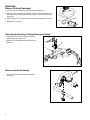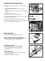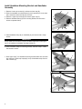
1
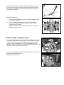
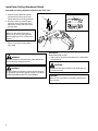
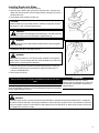
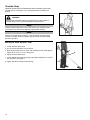
SHINDAIWA GRASS TRIMMER TO BRUSHCUTTER
CONVERSION KIT FOR T282 GRASS TRIMMER
MODEL: BCK-13
WARNING!
Minimize the risk of injury to yourself and others! Read the Owner's/Operator's manual originally supplied with the unit that is being upgraded and
familiarize yourself with the contents. Always wear eye and hearing protection when operating your unit.
X7672820301
02/11
Introduction
These are instructions to convert a grass trimmer to a blade capable unit. This is not an Owner's/Operator's manual. Information on how to operate and maintain the unit can be found in the Owner's/Operator's manual for the unit you are converting. Note this kit is supplied with a cutting attachment shield that has been redesigned to provide better visibility and a
larger cutting swath when used as a grass trimmer.
IMPORTANT!
IMPORTANT!
If the cutting attachment shield has been removed from
your unit or the unit was manufactured prior to October
2001, an additional clamp kit will be required to complete
this installation. The clamp kit required is Shindaiwa part
number 80293.
Contents
The information contained in these instructions describes
the product available at the time of publication.
Echo, Inc. reserves the right to make changes to products
without prior notice, and without obligation to make alterations to units previously manufactured.
PAGE
PAGE
PAGE
Attention Statements.........................2
General Safety Instructions...............3
Assembly...........................................4
Safety Labels.....................................3
Kit Contents.......................................3
Shoulder Strap................................10
Using a Brushcutter Blade............... 11
Attention Statements
Throughout this manual are special “attention statements”.
WARNING!
A statement preceded by the triangular attention symbol and the word “WARNING” contains information that should be
acted upon to prevent serious bodily injury.
CAUTION!
A statement preceded by the word “CAUTION” contains
information that should be acted upon to prevent mechanical
damage.
IMPORTANT!
A statement preceded by the word “IMPORTANT” is one that
possesses special significance.
NOTE:
A statement preceded by the word “NOTE” contains information
that is handy to know and may make your job easier.
IMPORTANT!
The instructions described in this manual are intended to help
you get the most from your Shindaiwa power tool as well as
to protect you and others from harm. These procedures are
guidelines for safe operation under most conditions, and are
not intended to replace any safety rules and/or laws that may
be in force in your area. If you have questions regarding your
Shindaiwa power tool, or if you do not understand something in
these instructions, your Shindaiwa dealer will be glad to assist
you. You may also contact Shindaiwa at the address printed on
the back of this instructional manual.
2
Read and follow this
operators manual.
Failure to do so could
result in serious injury.
Wear eye and hearing
protection at all times
during the operation
of this unit.
Keep bystanders
at least 50 feet (15 m)
away during operation.
Beware of thrown or
ricocheted objects.
Do not operate this unit
with a blade unless the
unit is equipped with a
Shindaiwa-approved
handlebar or barrier.
Always wear a harness
when operating this unit
with a blade. A harness
is also recommended when
using trimmer line.
If unit is used as a
brushcutter, beware of
blade thrust. A jammed
blade can cause the unit
to jerk suddenly and may
cause the operator to
lose control of the unit.
Safety Labels
IMPORTANT!
Safety and Operation Information Labels: Make sure
all information labels are undamaged and readable.
Immediately replace damaged or missing information
labels. A new label is provided in this kit and additional
labels are available from your local authorized Shindaiwa dealer. Prior to installing the new label, Remove
old label and clean the outer tube with rubbing alcohol
or similar cleaner.
General Safety Instructions
WARNING!
■■When operating with a blade, make sure the handle
is positioned to provide you with maximum protection from contacting the blade. Always make sure the
handlebar is installed in accordance with the manufacturers instruction.
■■NEVER use a cracked or warped blade: If a properly
installed blade vibrates, replace it with a new one and
re-check.
■■ALWAYS Shut off the engine immediately if a blade
binds in a cut. Push the branch or tree to ease the
bind and free the blade.
■■Beware of a coasting blade when brushcutting.
A coasting blade can injure while it continues to
spin after the throttle trigger is released or after the
engine is stopped.
Kit Contents
1
16
15
7
8
17
18
6
10
2
9
4
14
#
1
2
3
4
5
6
7
8
9
Description
Handlebar Assembly
Caution Label
Screw, 5 mm x 16 mm
Harness Hanger
Hex Nut, 5 mm
Handlebar Mounting Bracket
Plastic Clamp
Shim
Hex Bolt, 8 mm
Qty
1
1
1
1
1
1
2
2
1
13
12
11
5
3
10 Bolt Guard
11 Upper Shield Clamp
12Shim
13 Hex Bolt, 5 mm x 45 mm
14 Debris Shield
15 Debris Shield Extension
16 Shoulder Strap With Hip Cushion
17 Holder B
18 Holder A
Assembly Tool(s)
1
1
2
4
1
1
1
1
1
3
Assembly
Remove Cutting Attachment
1. Turn the unit over so that the gearcase output shaft faces UP.
2. Align the hole in the holder (A) with the notch in the gearcase flange, and
then temporarily lock the output shaft by inserting a hex wrench through
both holes.
A
3. While holding the hex wrench turn the trimmer head clockwise to remove.
4. Remove the hex wrench.
26107
Removing the Existing Cutting Attachment Shield
1. Remove the four socket-head cap screws (A),
bracket (B) and two shims (C).
2. Remove the cutting attachment shield from the
gearcase.
A
B
C
C
Remove Handle Assembly
1. Remove handle assembly. Retain all parts for
future use.
4
Disconnect Throttle Cable-Ignition Wires
1. Loosen air cleaner cover knob and remove air cleaner cover.
2. Remove wire end of throttle linkage cable (A) from carburetor throttle swivel hole.
3. Disconnect 2 ignition stop switch leads:
a. Disconnect wire with ring terminal from grounding screw (B) on engine.
b. Pull quick-connect connectors (C) apart to disconnect remaining stop switch wire.
C
D
Units with plain throttle cable end (P):
E
A
P
4.Remove throttle linkage cable from adjustment fixture (D).
5.Unscrew throttle cable adjustment fixture (D) and lock nut from carburetor
throttle cable bracket, and discard.
Units with throttle cable adjustment fixture attached to cable end (T):
T
6.Unscrew throttle linkage cable with attached cable adjustment fixture and
nut (T) from carburetor throttle cable bracket (E).
B
Remove Power Head
C
1. Loosen drive shaft clamping bolt (A).
2. Pull outer tube (B) and drive shaft out of power head (C).
A
B
Remove Throttle Control Handle Assembly
1. Loosen handle clamp screw (D), and remove throttle control assembly
and cushioned hand grip (F) from outer drive shaft tube.
D
Install Harness Hanger
1. Slide harness hanger (A) on to outer drive shaft tube (B)
and loosely attach with 5 mm x 12 mm screw (C) and nut
(D). Do not tighten screw securely until final adjustments
are completed.
Install Power Head
1. Slide outer drive shaft assembly into power head clamp, and align
power head with gear case.
F
A
C, D
B
2. Secure drive shaft assembly with clamping bolt.
5
Install Handlebar Mounting Bracket and Handlebar
Assembly
F
1. Remove 2 lower cap screws (A), and remove lower cap (B).
C
2. Place the handlebar mounting bracket (C) and 2 spacers (D) on the outer
tube, and secure with lower cap and 2 screws.
3. Remove 4 upper cap screws (E) and remove upper cap (F).
4. Remove handlebar clamp (G) from mounting bracket, and unscrew 4
screws to separate clamp.
E
D
E
B
D
E
A
G
5. Install handlebar clamp (G) on handlebar (H), and secure with 4 clamp
screws.
IMPORTANT!
Screw heads must face down to permit handlebar adjustments after upper
cap (F) is installed on handlebar mounting bracket (C).
6. Place handlebar clamp into mounting bracket, and seat clamp in rubber
anti-vibration cushion.
G
7. Place upper cap (F) on handlebar mounting bracket. Make sure anti-vibration cushions in upper cap fit properly on top of handlebar clamp. Secure
with 4 screws (E).
C
F
E
C
6
E
H
8. Secure plastic flex tubing to outer driveshaft tube using plastic clamps (I)
provided. Do not fully tighten plastic clamps until throttle cable and stop
switch wires are connected and all final throttle cable and handlebar adjustments are completed.
I
I
9. Handlebar Adjustments:
a. Loosen 2 lower cap retaining screws (A) to adjust handlebar location on outer drive shaft tube.
b. Loosen 4 handlebar clamp screws to adjust handgrip position. Access handlebar clamp screws through 4 holes (J) in bottom of handlebar mounting bracket.
c. Tighten all clamp and retaining screws securely after making final adjustments. (See page 10.)
J
E
J
E
J
E
A
E
J
Throttle Linkage and Ignition Leads
1. Thread throttle cable adjuster (A) into throttle cable bracket (B), and install
wire end into large carburetor swivel hole (C). Check throttle for freedom
of movement and that wide open throttle/low idle extremes are adjusted
properly. Turn the cable adjuster in or out to make adjustments. After
adjusting, hold the cable adjuster (A), and tighten the cable adjuster nut (D)
against the cable bracket (B) to lock the setting.
B
A
2. Connect 2 ignition stop leads from throttle cable tubing to ignition leads on
engine (E) and grounding screw (F).
C
D
E
3. Reinstall the air cleaner cover.
F
7
Install New Cutting Attachment Shield
Assemble the Cutting Attachment Shield to the Outer Tube.
1. Insert the cutting attachment shield
(A) between the outer tube and the
cutting attachment mounting plate (B).
A
E
2. Fit the two shims (C) and the upper
clamp (D) over the outer tube and install the four socket-head cap screws
(E) finger tight.
CAUTION!
D
G
C
Make sure the clamp screw and retaining nut (F) are securely tightened
before tightening the four socket head
screws.
3. Tighten the four socket-head cap
screws to secure the cutting attachment shield.
A
C
B
F
Sub-Shield.
WARNING!
NEVER operate the unit without the cutting attachment
shield installed and tightly secured!
(when trimmer head is in use)
1. Attach the sub-shield (G) extension to the cutting attachment shield (A).
WARNING!
WARNING!
A cutting attachment shield or other protective device is
no guarantee of protection against ricochet. YOU MUST
ALWAYS GUARD AGAINST FLYING DEBRIS!
NEVER use this machine without sub-shield when using a trimmer head.
CAUTION!
Make sure the sub-shield is completely hooked at the
hook receiver.
8
Installing Brushcutter Blade
D
2. Align the hole in blade holder (A) with the matching hole in the gear case
flange and then temporarily lock the output shaft by inserting a hex wrench
through both holes.
C
1. Install blade holder (A) onto output shaft (G).
B
3. Fit the blade over the flange on holder (A).
G
CAUTION!
A
Install the blade (E) so its printed surface is visible to the operator when the
brushcutter is in the normal operating position.
WARNING!
The blade must fit flat against the holder flange. The blade mounting
hole must be centered over the raised boss on blade Holder (A).
WARNING!
Holder (B) must fit flush against the blade and the splines engaged
to the output shaft.
E
4. nstall blade holder (B) on the output shaft (G).
WARNING!
Do not attach any blade to a unit without proper installation of all required
parts. Failure to use the proper parts can cause the blade to fly off and seriously injure the operator and/or bystanders.
B
5. Install the bolt guard (C) and then the blade retaining bolt (D). Using the
combination spark plug wrench/screwdriver, tighten the bolt firmly in a
counter-clockwise direction.
6. Remove the hex wrench.
The unit should now be completely assembled and ready for use with a
blade.
IMPORTANT!
Units with adjustable carburetors must be readjusted for blade use, otherwise
serious engine damage can occur.
IMPORTANT!
Discard blades that are bent, warped,
cracked, broken or damaged in any way.Use
a sharp blade. A dull blade is more likely to
snag and thrust.
WARNING!
A standard grass trimmer unit with loop handle should NEVER be operated with blade-type attachments. For blade use,
the trimmer must be fitted with a bicycle-type handlebar or barrier bar that is located in front of the operator to reduce the
risk of the operator coming in contact with the cutting attachment. (Per ANSI B175.3). When using a blade, the unit must
be equipped with a harness or strap.
9
Shoulder Strap
Adjust the shoulder strap so the shoulder pad rests comfortably on the off-side
shoulder and the cutting path of the cutting attachment is parallel to the
ground.
WARNING!
Always wear a shoulder strap when operating this unit with a blade. A
shoulder strap is also recommended when using trimmer line.
NOTE:
Using a shoulder strap with a brush-cutter allows you to maintain proper
control of the unit and reduces fatigue during extended operation.
NOTE:
Although a shoulder strap accessory is not required for use with a grass
trimmer, a shoulder strap can increase operator comfort during extended
periods of operation.
balance and adjust unit
1. Loosen harness clamp screw.
2. Put on harness and attach unit to harness.
3. Slide harness clamp up (A) or down until unit balances with head approximately 50-75 mm (2 -3 in.) from the ground.
B
4. Tighten harness clamp screw.
5. Loosen Handle bar clamp screws (B), and position Handle bar for comfortable operation. (See page 7.)
6. Tighten Handle bar clamp screws securely.
10
A
Using A Brushcutter Blade
WARNING!
■■Before working with a blade-equipped unit, always inspect and clear the area of objects that could interfere with or
damage the blade.
■■Never use a blade near sidewalks, fence posts, buildings or other objects that could cause injury or damage.
■■Never use a blade for purposes other than those for which it was designed.
■■Whenever you strike a hard object with a blade, always stop the brushcutter and carefully inspect the blade for damage. NEVER OPERATE THE UNIT WITH A DAMAGED BLADE!
■■A blade-equipped unit must be equipped with a bicycle-type handlebar or barrier as well as a harness or strap.
■■Always make sure the cutting attachment shield is properly installed before operating the unit.
Blade Thrust
‘Blade thrust’ is a sudden sideways or backward motion of the brushcutter.
Such motion may occur when the blade jams or catches on an object such
as a sapling tree or tree stump. BE CONSTANTLY ALERT FOR BLADE
THRUST AND GUARD AGAINST ITS EFFECTS!
Eleven
O’Clock
Handle Bar
A brushcutter’s handle bar helps prevent the operator from moving forward,
or the unit moving rearward, thus preventing inadvertent bodily contact with
the blade. ALWAYS KEEP THE HANDLE BAR SECURELY IN PLACE ON
THE UNIT!
DO NOT C
UT
Blade
Rotation
OK To Cut
Shoulder Strap or Harness
A shoulder strap or harness provides additional protection against blade
thrust. In addition, a shoulder strap or harness gives significant support and
comfort to help ensure safe and efficient operation.
When operating a unit equipped with a blade, make sure both the handle/
barrier bar and shoulder strap or harness are adjusted to the size of the
operator using the unit.
The blade rotates counter-clockwise. For best performance and to minimize
being struck by debris, move the blade from right to left while advancing on
your work. Position the blade so cuts are made between the blade’s 7 o’clock
and 11 o’clock positions (as viewed from above). DO NOT cut between the
11 o’clock and 5 o’clock positions (shaded area).
Seven
O’Clock
Five
O’Clock
BCC17
11
Consumer Product Support
If you require assistance or have questions concerning the application, operation or maintenance of this product you
may call the Shindaiwa Consumer Product Support Department at 1-877-986-7783 from 8:30 am to 4:30 pm (Central
Standard Time) Monday through Friday. Before calling, please know the model and serial number of your unit.
ECHO Incorporated.
400 Oakwood Road
Lake Zurich, IL 60047-1564 U.S.A.
Telephone: 1-877-986-7783
Fax: 1-847-540-8416
www.shindaiwa.com
Copyright© 2011 By Echo, Incorporated
All Rights Reserved.
Yamabiko Corporation
7-2 Suehirocho 1-Chome, Ohme,
Tokyo, 198-8760, Japan
Phone: 81-428-32-6118
Fax: 81-428-32-6145