1
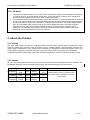
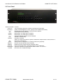
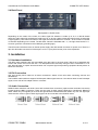
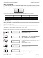
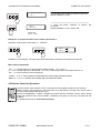
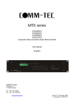
MTX series
MTX0808DA
MTX1608DA
MTX1616DA
DVI and Stereo-Audio Matrix Switcher
User Manual
(English)
COMM-TEC GmbH
Siemensstr. 14
D-73066 Uhingen
Tel.: +49-7161-3000-0
Fax: +49-7161-3000-333
www.comm-tec.de
Version A1- June 2009
© Copyright by COMM-TEC
User Manual for DVI/Stereo-Audio Matrix
COMM-TEC MTX Series
Table of Contents
1. Safety Warnings / Precautions...................................................................................................................................2
2. About the Product ......................................................................................................................................................3
3. Installation ..................................................................................................................................................................5
4. Operation ...................................................................................................................................................................6
5. Specifications .............................................................................................................................................................9
6. Warranty, Service and Returns Policy .....................................................................................................................10
1. Safety Warnings / Precautions
Please read this manual carefully before using your Matrix Switcher. It is recommended that you keep this
manual handy for future reference. These safety instructions are to ensure the long life of your MTX unit and to
prevent fire and shock hazard. Please read them carefully and follow all warnings.
1.1 General
•
•
•
Do not open the cover of the equipment since there are high-voltage components inside creating the
risk of electric shock.
Qualified Comm-Tec service personnel, or authorized representatives must perform all service. Service
preformed by unauthorized personnel without prior approval will void the warranty.
Changes or modifications not expressly approved by the manufacturer (responsible for compliance)
could void the user’s authority to operate the equipment.
1.2 Installation
•
•
•
•
•
•
•
For best results, place the unit on a flat, level surface in a dry area away from dust and moisture.
Handle the Matrix Switcher carefully. Dropping or jarring can damage internal components.
Do not place heavy objects on top of the equipment.
To prevent fire or shock, do not expose this unit to rain or excessive moisture. Do not place the
equipment in direct sunlight, near heaters or heat radiating appliances, or near any liquid. Exposure to
direct sunlight, smoke, or steam can harm internal components.
To turn off the main power, be sure to remove the power cord from the power outlet. The power outlet
socket should be installed as near to the equipment as possible and should be easily accessible. Make
sure the outlet is properly grounded for safety as per local regulations.
Do not pull the power cord or any cable that is attached to the equipment.
If the equipment is not used for an extended period, disconnect the power cord from the outlet to avoid
fire, shock, and loss of power.
1.3 Safety Guidelines for the Rack-Mounting of the Equipment.
•
•
•
•
•
Never restrict the airflow through the equipments’ fan or vents.
Normal operating ambient temperature is between 40-100 degrees F (5 – 40°C).
When installing equipment into a rack, distribute the units evenly. It is recommended to leave one space
on top and bottom of equipment.
Connect the unit to a properly rated power circuit (100V - 240V, 50/60Hz).
Reliable grounding of the Rack-Mounted Equipment should be maintained.
1.4 Cleaning
•
Unplug the equipment power cord before cleaning. Clean surfaces with a dry cloth. Never use strong
detergents or solvents, such as alcohol or thinner. Do not use a wet cloth or water to clean the unit.
COMM-TEC GMBH
www.comm-tec.de
2 of 11
User Manual for DVI/Stereo-Audio Matrix
COMM-TEC MTX Series
FCC / CE Notice
•
•
This device complies with part 15 or the FCC Rules. Operation is subject to the following two conditions:
(1) This device may not cause harmful interference, and (2) this device must accept any interference
received, including interference that may cause undesired operation.
This equipment has been tested and found to comply with the limits for a Class A digital device, pursuant
to Part 15 of the FCC Rules. These limits are designed to provide reasonable protection against harmful
interference when the equipment is operated in a commercial environment. This equipment generates,
uses, and can radiate radio frequency energy and, if not installed and used in accordance with the
instruction manual, may cause harmful interference to radio communications. Operation of this
equipment in a residential area is likely to cause harmful interference in which case the user will be
required to correct the interference at his own expense.
2. About the Product
2.1 Function
The MTX series Matrix Switcher is a high-performance pro-AV matrix switcher that is designed for cross
switching multiple DVI computer video and audio inputs to multiple outputs. The MTX series switchers are
mostly used in presentation rooms, board-rooms, broadcast TV engineering, multi-media meeting rooms, big
screen display engineering, television education, command control centers, and many other installations.
COMM-TEC provides a wide range of AV matrix switchers ranging from 4-inputs to 256 and 2-outputs to 256.
2.2 Features
All video signal connectors are DVI-D female, the audio connectors are provided with 5pin screw terminals. The
MTX Matrix Switchers can be controlled via front panel, with Infrared Remote or via RS-232 port.
Type
Configuration Video
Audio
5 pin screw
Unit Height
MTX0808DA
8x8
DVI-D
terminal
5 pin screw
3 ru
MTX1608DA
16x8
DVI-D
terminal
5 pin screw
7 ru
MTX1616DA
16x16
DVI-D
terminal
7 ru
COMM-TEC GMBH
www.comm-tec.de
Accessories included
Infrared Remote, power cord, RS-232 cable,
Quick-Start- Guide, CD-ROM with Software
and Manuals
3 of 11
User Manual for DVI/Stereo-Audio Matrix
COMM-TEC MTX Series
2.3 Front Panel
Button/*Indication Function
The LCD-Display shows the entered commands and messages
COMM-TEC
MTX0808DA
(status, acknowledgement, errors, prompt, matrix model and firmware)
0-9
Number entry for I/O selection, save and recall of presets
AV
Audio-follows-Video switching
VIDEO
Break-Away, only Video part is switched
AUDIO
Break-Away, only Audio part is switched
/
separates different numbers in one command
END
Finishes command entry
ENTER
Executes command
Option: one input to all outputs, inputs are switched to outputs with the same number or
disconnect of all routings
ALL
SAVE
Saves present configuration in a preset (number entry required)
RECALL
Recall of a preset (number entry required)
CANCEL
Deletes last entry or/and returnes to standby status
STATUS
Shows the present Video- and Audioroutings in the LCD display
*THROUGH
Inputs are switched to outputs with the same number: 1 to 1, 2 to 2,....
*CLOSE
Disconnect all crosspoints/routings
COMM-TEC GMBH
www.comm-tec.de
4 of 11
User Manual for DVI/Stereo-Audio Matrix
COMM-TEC MTX Series
2.4 Back Panel
Back panel 8 x 8 with Audio
Depending on the model of the matrix, the video signal I/O interface is made up of 8 or 16 DVI-D female
terminals. Audio signal I/O terminals are made up of 8 or 16 5pin captive screw terminals for each channel (left
& right together). The channel numbers of the signal I/O terminals start from channel 1 to the maximum number
of channels depending on the model. The left audio channel is indicated with L +/-, the right channel with R +/-.
Common ground is connected to the middle pin (grounding sign).
The MTX matrix switchers have an internal power supply with IEC female connector for power cord. There is a
9pin Sub D female connector for RS-232 port. An RJ-11 port (AUX Control) is for future expansion.
3. Installation
3.1 Hardware Installation
The MTX matrix switchers are rack-mountable using the holes in the front panel. Take a set of standard rack
screws and secure the unit into the rack. For ideal performance and easy wiring access it is advisable in a 19“
rack leave at least 1ru space above and below. Do not place high heat-producing equipment directly above or
below the enclosure.
3.2 DVI Connection
Use good quality DVI-D cable for all video connections. Switch off all units while connecting sources and
destinations.
The DA MTX matrix switchers support DVIComputer Video signal sources. If the device doesn’t have DVIoutput
signal, use a VGA to DVI adapter cable or converter.
3.3 Audio Connection
RGBHV Matrix switchers with audio come with terminal block connectors (captive screw terminals connectors)
located under the BNC connectors. There are two types of audio signals: balanced or unbalanced. Balanced
audio cables carry two signals per channel and ground while unbalanced audio cables only use one signal per
channel and a common ground. Both signal types can be connected to the RA MTX series.
COMM-TEC GMBH
www.comm-tec.de
5 of 11
User Manual for DVI/Stereo-Audio Matrix
COMM-TEC MTX Series
3.4 RS-232 Connection
All functions of the MTX units can be controlled with external controllers like computers or third party controllers
(e.g. AMX). A serial controller is any device that is connected to the standard RS-232 serial port (9pin SubD
female) on the rear panel and that can send and receive ASCII character format.
The port settings are:
BAUD
Data Bits
Stop Bit
Parity
9600
8
1
NONE
Connect serial controllers refering to the table below for RS-232 cable connector pin mapping:
Description
Pin-#. at UP-1280SU
RS-232 Port
2
3
5
Pin-# at PC
RS-232 Port
2
3
5
Tx Transmit
Rx Receive
Gnd Ground
Description
Rx Receive
Tx Transmit
Gnd Ground
4. Operation
The DVI matrix switcher can be controlled by the front control panel, infrared remote controller, Ethernet control
(optional), and the RS-232 communication port.
4.1 Front Panel Operation
Using the front control panel, the switcher can be controlled directly by pressing the buttons using this format:
“Input Channel” + “Switching Mode” + “Output Channel” + “End” + “Enter”
Example 1: Transfer video and audio signals from input channel 1 to output channels 3 and 4
1
2
3
4
Input Command:
1
AV
Video
Audio
Input Command:
1B
2
3
Input Comm and:
/
Input Comm and:
END
1B3,
2
2. Press the button for switching mode “AV”.
Display feedback on LCD: “B” (“B” for both audio and
video, “A” for audio only; “V” for video only).
4
1B3
0
1. Press the button for input channel number “1”.
Display feedback on LCD: “1”
3
4
Input Comm and:
1B3, 4
COMM-TEC GMBH
3. Press the button for the first output channel
number”3”.
Display feedback on LCD: “3”
4. Press the break button “/”.
Display feedback on LCD: “,”
5. Press the button for the second output channel
number “4”.
Display feedback on LCD: “4”
www.comm-tec.de
6 of 11
User Manual for DVI/Stereo-Audio Matrix
COMM-TEC MTX Series
Input Comm and:
0
/
ENTER
END
1B3, 4.
7. Press the button “ENTER” to perform this
command.
Display feedback on LCD: “Switch OK”
1B3,4.
RECALL
6. Press the button “END” to finish the command.
Display feedback on LCD: “.”
Switch OK
Switch OK!
AV: 01 -> 004
Example 2: To inquire the status on the output channel No.4
Operation: Press buttons in this order “4”, “STATUS”
2
3
4
RECALL CANCEL
STATUS
VIDEO : 3
AUDIO: 2
4
4
Feedback on LCD-Display: The video input #3 and the audio input #2 are switched to the output #4.
More switch commands:
„ALL“ + „1“: Routes inputs to outputs with the same number: 1 to 1, 2 to 2,....
„1“ + „ALL“: Routes input #1 to all outputs, <2> <ALL>: Routes Input #2 to all outputs, and so on.
„ALL“ + „2“: Disconnects all routed crosspoints.
„SAVE“ + „0“ to „9“: Saves present configuration as preset under selected number.
„RECALL“ + „0“ to „9“: Recalls saved preset with the selected number.
4.2 Remote Controller Operation
The MTX series matrix switcher can be controlled with the supplied infrared remote controller.
Button functions are the same as with front panel. Only the buttons „Through“ and „Close“ have a
functions when pressed directly after „ALL“.
The keys <PROGRAM>, <UNDO>, <DEMO> are without function. Attention <LOCK> button: before
usage set password with control software. Otherwise front panel can be only unlocked with this
software.
For details please refer to Front Panel Operation.
COMM-TEC GMBH
www.comm-tec.de
7 of 11
User Manual for DVI/Stereo-Audio Matrix
COMM-TEC MTX Series
4.3 RS-232 Operation
Through the RS-232 port located on rear panel one is able to control and operate the MTX Matrix remotely.
Communication protocol: RS-232, ASCII commands are case sensitive.
Port Settings: Baud rate: 9600, Data bit: 8, Stop bit: 1, Parity bit: None
ASCII
Commands and
Protocols
Example
Default
Rewrites the password. Must be 8 digits.
/+xxxxxxxx;
/+12345678;
None
Locks the keyboard
/%Lock;
/%Lock;
Not Locked
Unlocks the keyboard
/%Unlock;
/%Unlock;
N/A
Turns OFF buzzer
/:Belloff;
/:Belloff;
Beep ON
Turns ON buzzer
/:Bellon;
/:Bellon;
N/A
Sets the delay time for background light in minutes.
Range: 001 to 240.
/%Backlightxxx;
/%Backlight005;
30 min.
Connects input "x" to ALL output channels.
Connects the video signal from input "x" to the matching
output.
xAll.
3All.
N/A
x#.
4#.
Not Connected
Connects ALL input signals to the matching output channels.
All#.
All#.
N/A
Switches OFF ALL the output channels.
All$.
All$.
All ON.
Switches OFF output "y".
y$.
2$.
N/A
Connects video from input "x" to output "y".
xVy.
2V3.
N/A
Connects video from input "x" to outputs "y, y2, y3".
xVy,y2,y3.
1V3,4,5.
N/A
Connects audio from input "x" to output "y".
xAy.
2A4.
N/A
Connects audio from input "x" to outputs "y, y2, y3".
xAy,y2,y3.
1A2,3,4.
N/A
Connects video and audio from input "x" to output "y".
xBy.
3B5.
N/A
Connects video and audio from input "x" to outputs "y, y2, y3".
xBy,y2,y3.
2B4,5,6.
N/A
Connects input "x" to ALL outputs in group "g".
xPg.
1P1.
N/A
Groups the outputs "y, y2, and y3" under the group "g".
Saves configuration to the preset command "y". "y" ranges
from 0 to 9.
gPPy,y2,y3.
2PP1,2,3.
N/A
Savey.
Save9.
All Available
Recalls the preset command "y".
Recally.
Recall7.
N/A
Clears the preset command "y".
Cleary.
Clear5.
N/A
Displays the outputs channels in Group "g".
Sg.
S2.
N/A
Displays the input channel of output "y".
Statusy.
Status4.
N/A
Displays the inputs to the connected outputs one by one.
Status.
Status.
Displays the models information.
/*Type;
/*Type;
N/A
Varies per
model
Displays Software Version
/^Version;
/^Version;
V2.z
Displays COM port feedback information.
/:MessageOn;
/:MessageOn;
N/A
Functions
System Command
Operation/Control Command
Feedback/Status Command
COMM-TEC GMBH
www.comm-tec.de
8 of 11
User Manual for DVI/Stereo-Audio Matrix
COMM-TEC MTX Series
5. Specifications
Type
Spezifikationen
Video
Bandwidth
MTX0808DA
MTX1608DA,
MTX1616DA
165MHz (-3dB), all digital
Resolution
1600x1200 @60 bit Clock Jitter: <0.15Tbit
Switching speed
Video input
200ns
Connector
DVI-D female
Signal strength
T.M.D.S +/- 0.4Vpp
Maximum/Minimum level
T.M.D.S 2.9V/3.3V
Resistance
50 Ω
Max. distance
< than 36m, 1600x1200@60Hz
Video Output
Connector
Maximum/Minimum level
DVI-D female
T.M.D.S 2.9V/3.3V
Resistance
Max. distance
50 Ω
< than 7m, 1600x1200@60Hz
Audio Signal
I/O connector
3.8 mm with screw, 5 pole
Gain
0dB
Frequency respond
20 Hz - 20 kHz
General harmonic
distortion + noise
S/N
Segregation rate
0,03% bei 1 kHz
>90dB
>80dB @1 kHz
CMRR
Signal
Impedance
>75dB @ 20 Hz - 20 kHz
Stereo, balanced
Eingang: >10 kΩ (balanced/ unbalacend)
Ausgang: 50 Ω (unbalanced), 100 Ω (unbalanced)
+19,5dBu, (balanced/ unbalanced)
±0,1dB
+19,5dBu (balanced/ unbalancend)
Max. input level
Gain error
Max. output level
Control type
Serial control port
RS-232, 9-pin Sub D connector female
Baudrate and protocol
Serial port pin out
Command/ protocol
Sonstiges
Power supply
temperature
humidity
Dimensions
(W x D x H) / HE
weight
MTBF
Warranty
COMM-TEC GMBH
Baudrate: 9600, Data bit: 8, Stop bit: 1, Parity bit: none
2 = TX, 3 = RX, 5 = GND
ASCII
100V - 240V~, 50/60 Hz, universal international power
Storing and operating temperature: 5° - +40°C
Storing and operating humidity: 10% - 90%
483 x 260 x 133,5mm – 3ru
483 x 260 x 312mm – 7ru
4,2 kg
10kg
30.000 hours
1 year
www.comm-tec.de
9 of 11
User Manual for DVI/Stereo-Audio Matrix
COMM-TEC MTX Series
6. Warranty, Service and Returns Policy
This product is under warranty for a period of one (1) year from the date of purchase.
COMM-TEC’s liability and Buyer’s remedies under this warranty shall be limited solely to repair of the faulty
units free of charge.
This warranty does not apply if the product has been modified, repaired by an unauthorized agent, or
improperly installed, used, or maintained.
If a problem occurs first contact your dealer or COMM-TEC for trouble shooting.
If verification of a problem requires factory repair, ask COMM-TEC’s representative to issue a
Return Materials Authorization (RMA) number.
Merchandise will not be accepted without a RMA number.
When returning a product to COMM-TEC in Uhingen for repair please comply with the following instructions:
• Shipping and insurance costs must be prepaid
• Use original shipping container(s), (if possible)
• Indicate the RMA number clearly on the outside of each container
• Enclose a written description of the problem
The under warranty repaired units will be returned Carriage Free to the sending party (dealer or consumer).
Outside the warranty period, COMM-TEC will repair the faulty units, charging all arising expenses of the repair
e.g. labor, parts, transportation and insurance, to the sending party (dealer or consumer).
For any problems during installation and operation of a MTX series unit
call the COMM-TEC hotline +49 07161 3000-0,
send a fax +49 07161 3000-333
or e-mail to [email protected]
COMM-TEC GMBH
www.comm-tec.de
10 of 11