1
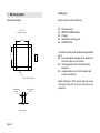
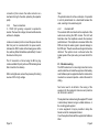
bhi ltd
P.O. Box 136
Bexhill on Sea
East Sussex
TN39 3WD
tel: +44 (0)870 240 72 58
fax: +44 (0)870 240 72 59
[email protected]
www.bhi-ltd.co.uk
Page 20
Sound Engineering Solutions from bhi
Sound Engineering Solutions
bhi
bhi
NEDSP1061-KBD
Noise Eliminating PCB Module
Generic Installation
and
Operating Manual
1061-110D
Issue A
Page 1
Important Information
Notes:
Copyright
This publication, including all photographs and illustrations is
protected under international copyright laws, with all rights reserved.
Neither this manual, nor any of the material within, may be copied
or reproduced without the written consent of bhi Ltd.
Disclaimer
The information in this document is subject to change without notice.
bhi Ltd. makes no representations or warranties with respect to the
contents hereof and specifically disclaims any implied warranties of
merchantability or fitness for any particular purpose. Furthermore,
bhi Ltd. reserves the right to revise this publication and to make
changes from time to time in the content hereof without obligation
of bhi Ltd. to notify any person of such revision or changes.
The fitting of the bhi NEDSP1061-KBD module may involve the
removal of small surface mount components and the drilling out of
the transceivers’ case. This should only be carried out by a qualified
engineer. bhi accepts no responsibility for the fitting or installation
of the NEDSP1061-KBD module and are not liable for any damage
to equipment caused by its fitment. Fitting this module may invalidate
your warranty.
All attempts have been made to ensure that this information is up to
date. It is possible that these instructions contain errors, or the
equipment is slightly different to the one used to compile this
information. In all cases it is up to the installer to ensure that the
module is fitted correctly.
By installing this module you are doing so at your own risk.
Page 2
Page 19
Packing List:
7. Machining details
Hole machining details.
Please check the contents of the box.
n
n
n
n
n
DSP PCB
Mounting hole detail
27.3mm
Operating manual
NEDSP1061-KBD assembly
Z bracket
Self adhesive mounting pads
bhi NEDSP label
21.0mm
To install this module you will need the following additional
items:
n
service manual/circuit diagram of the equipment in
which the module is to be installed.
n
all the appropriate tools to disassembling the
equipment
n
suitable soldering iron and bits for working with
surface mount devices.
4 holes 3.0mm diameter
4.0mm diameter
(switch)
3.5mm diameter
(LED)
Before attempting to fit this module study this manual
thoroughly along with the service manual for your
equipment.
5.1mm
Keyboard holes
Page 18
Page 3
Contents
1.
Introduction
1.1 NEDSP1061-KBD features
1.2 Limitations
1.3 Audio DSP noise cancellation
5
5
6
6.3.2
Demonstration 2:
Follow the procedure as above. Wait for the second 2
tone beep, then release the key.
In this mode the filter level is set to level 3.
2.
Module description
2.1 Module layout
2.2 Connections
2.3 Electrical characteristics
2.4 Controls
2.4.1
Input level
2.4.2
Output level
2.4.3
Beep volume level
2.4.4
Overload LED
2.5 Module mounting
7
7
8
8
8
8
8
8
9
Installation
3.1 Introduction
3.2 Circuit location
3.3 Fitting
3.3.1
Audio connections
3.3.2
Power connections
10
10
10
11
11
12
6.4 Notes about the noise reduction.
When using the module on level 4 some distortion may
be heard. This is quite normal when listening to high
levels of noise at level 4.
4.
Setup
13
6.5 Noise reduction levels.
5.
Troubleshooting
14
L evel
Tone Reduction
White Noise
Reduction
6.
Operation
6.1 Introduction
6.2 Operation
6.3 Demonstration mode
6.4 Notes about noise reduction
6.5 Noise redcution level
Machining drawings
15
15
15
16
16
17
18
1
5dB
11dB
2
8dB
13dB
3
21dB
20dB
4
65dB
35dB
3.
7.
Page 4
The noise cancellation is switched on for 3 seconds, then
off for 3 seconds. This loops until the user aborts this
mode.
This is a good demonstration for listening noisy SSB
conversations showing the before and after.
6.3.3
Exiting the demonstration mode.
Hold down the button until the 2 tone beep is heard.
Release the button.
After a short delay the LED will flash indicating the stored
level, as during the normal switch on.
Page 17
Noise cancellation on/off.
Press and release the button and the led will extinguish,
and the noise cancellation will be activated. A short beep
will acknowledge the key press.
Changing the filter level.
Hold down the button. The led will flash the filter level,
and if the button is held it will step through all the levels.
When the desired level has been reached release the
button. This new value will be stored in the modules’
memory and will be the default setting the next time the
unit is powered up.
6.3. Demonstration mode.
The NEDSP1061-KBD module features 2 preset
demonstration modes. These demonstrate the noise
cancellation abilities of the NEDSP1061 module.
6.3.1
Demonstration 1:
Hold down the button and switch on the equipment. After
a short time the unit will emit a 2 tone beep. Release
the button. The unit is now in demonstration mode 1.
The module will switch the noise cancellation on for 1.5
seconds, then off for 1.5 seconds. It will then move onto
the next level and repeat this continuously through all 4
levels.
This mode a particularly effective when the equipment
is just receiving static, as it demonstrates the attenuation
of white noise at all the levels.
Alternatively tune the equipment into a good quality FM
speech broadcast. This demonstration shows how little
the DSP alters the speech, at any of the levels.
Page 16
1. Introduction
The NEDSP1061-KBD is a modular solution to noise
reduction. It incorporates DSP technology to provide up
to 35dB of noise cancellation. The module is controlled
by a single pushbutton with LED indication for ease of
use.
1.1 NEDSP1061-KBD module features:
n
n
n
n
n
n
n
n
n
n
n
Fully adaptive to changing noise environments
Input and output level controls
Input overload indication
Virtually no distortion to speech signal
Up to 35dB of noise cancellation
4 levels of noise reduction
5 – 15V supply range
4.6dB on board gain
Single key operation of all functions
LED indication of DSP level and status
Small size 26mm x 37mm
1.2 Limitations.
This module is designed to pass speech. Other signals
such as data and music will to some degree pass
through, but the integrity of these signals
cannot be guaranteed.
This module is designed to be placed in a low level audio
path only. The module will not drive a loudspeaker or
other high power load (see bhi amplified DSP module).
The unit is single channel (mono).
Page 5
This module is designed for communication type
applications. The upper frequency limit is 4.5KHz and
therefore not suitable for hi fidelity applications.
1.3 Audio DSP Noise cancellation.
The bhi DSP processes the incoming audio signal and
then differentiates the speech from the noise. The
unwanted noise and interference is then attenuated to
leave only the speech.
The following diagrams are taken from actual audio
signals and illustrate how the audio signal is being
processed.
Speech
Noise
Original signal.
Speech with a lot of
background noise
Processed speech.
Speech with reduced
noise
Reduced noise
6. Operation
6.1 Introduction.
All functions of the NEDSP1061-KBD are controlled by
a single button.
•
•
Single press turns the noise cancellation on/off.
Holding down the button changes the DSP filter
level.
The mode of operation is indicated both visually and
audibly.
The LED is illuminated red when the noise cancellation
is off.
When the noise cancellation level is changed the LED
will flash green to indicate which level has been selected.
Simultaneously the DSP will beep to give audible
indication of DSP level. This allows the operator to change
the DSP level without having to look at the LED to see
which level has been selected.
A short beep is emitted to acknowledge a button press.
The module will store the current DSP level, and will return
to this level when the equipment is switched on.
6.2 Operation.
Switch on the equipment.
The LED will illuminate red to indicate the noise
cancellation is off. The unit will flash/beep to indicate the
DSP filter level last used.
Figure 1. Noise cancellation.
Page 6
Page 15
5. Troubleshooting
2. Module description
2.1 Module Layout.
Start
The following diagram shows the layout of the
NEDSP1061-KBD module.
Audio
Distortion
Overload
LED
Illuminates
(P1)
Yes
Output
level
Overload
LED
Input
level (P2)
+
+
Keyboard
PCB
+
Reduce Input
Level using P2.
No
Reduce Output
Level using P1.
Pushbutton
DSP
PCB
Mounting
holes
(4 off)
M3 Ring Tag
(0V)
Top
Red wire
(5-15VDC)
Beep volume
control
Bi Colour
LED
Screened Audio Lead
(Audio In/Out)
(P3)
Yes
Distortion
Figure 2. Module layout.
2.2 Module Connections.
No
The NEDSP1061-KBD module has five connections.
End
Figure 6. Troubleshooting flowchart.
Page 14
Red wire:
M3 Tag:
Screened Lead:
5 - 15VDC
0V
Red
Blue
Black
Audio In
Audio Out
Audio Screen
Page 7
2.3 Electrical characteristics.
4. Setup
Electrical Characteristics
Parameter
Description
V in
Supply voltage
Iin
Supply current
In
Audio input signal
Out
Audio output signal
(1.7 Xs input max)
Min
Typ
Max
Units
5
9
15
V
45
50
mA
50
300
Vrms
630
Vrms
Table 1. NEDSP1061-KBD Electrical characeristics
The levels come factory set to the maximum position.
This should be adequate for most applications. However
the module can be adjusted as follows.
Tune the equipment to a strong signal.
Switch off the noise reduction (LED will illuminate RED).
Adjust the input P2 until the overload led illuminates.
Back off the pot slightly.
2.4 Controls.
Adjust P3 to give the correct listening volume, without
distortion.
Controls are provided to allow the NEDSP1061-KBD to
be integrated in to the target system. 3 level controls are
provided.
Adjust P1 to give the desired beep volume level, or off if
required.
2.4.1
Input Level:
To set the audio level to the optimum level for the DSP.
2.4.2
Output Level:
To match the output level of the DSP module to that of
the following stage.
2.4.3
Beep volume level:
Allows the user to adjust the beep volume control to suit.
The beep volume can be reduced to zero if required.
The modules are factory set to the maximum level.
Turning the potentiometers anti clock wise will increase
the levels.
Page 8
Page 13
connection (this screens the cable and acts as a
mechanical fixing for the cable, protecting the capacitor
pads).
3.3.2
Power connections.
5 - 15VDC (9V typically) is required to operate the
module. The lower the voltage, the less heat the module
will have to dissipate.
Locate a convenient point to connect the power. Ensure
that this point is connected after the power switch,
otherwise the DSP module will be drawing power all the
time, and may flatten the batteries (where fitted). Connect
the red wire to this point.
The 0V connection is formed using the M3 ring tag.
Locate a suitable 0V point (such as a PCB retaining screw
that is fixed into the chassis).
When routing the wires, ensure they are away from strong
sources of RF or high voltage.
Note:
The potentiometers do not have end stops. It is possible
to set the potentiometer in a dead band between the
ends, resulting in the audio being lost.
2.4.4
Overload LED.
The overload LED circuit monitors the amplitude of the
audio level entering the DSP module. The LED will
illuminate when the amplitude exceeds the maximum
permitted level. If the amplitude is increased further the
DSP will clamp the audio signal to prevent damage to
the DSP input. This will cause the audio signal to become
distorted. The optimum level is achieved when the
loudest peaks of the input audio, just cause the LED to
glow.
2.5 Module mounting.
The DSP module has four mounting holes that can be
used to retain the unit inside the equipment. Alternatively
a self adhesive pad is supplied to allow the module to be
mounted in a convenient position - without the need for
drilling.
Two holes need to be drilled in the casing of the
equipment for the keyboard. Hole sizes and positions
can be found in section 7.
The keyboard can retained using the supplied ‘Z’ bracket
or alternatively retained using a suitable adhesive, or
the mounting pads supplied.
In some equipment it may be possible to clamp the
bracket under the loudspeaker bracket.
Cover the keyboard holes with the supplied self adhesive
label.
Page 12
Page 9
Audio source
Pre-amp
Volume
Control
Loudspeaker
Audio Out
(Blue)
3.2 Circuit location.
The NEDSP1061-KBD module is inserted into the path
of noisy audio. Using the input and output level controls
allows the unit to appear transparent to the audio signal.
Coupling Capacitor
Audio In
(Red)
3.1 Introduction.
Before commencing installation study the equipment’s
service manual/circuit diagram thoroughly to familiarise
yourself with the circuit diagram and disassembly
procedure.
For optimum performance provide the module with a
constant amplitude signal, for example before the volume
control.
Remove this
Black
(Screen)
3. Installation
Power Amp
NEDSP1061
Audio out
Pre amp
NEDSP1061
Place the NEDSP1061
In place of the
Coupling capacitor
Power amp
Figure 5. NEDSP1061-KBD recommended position.
Note:
On some modern receivers/transceivers the volume
control is digital and doesn’t operate in the audio
path.Contact the manufacturer for advise for the most
suitable postion for theDSP module..
Figure 3. Basic connection diagram
Place NEDSP1061-KBD module
in place of the coupling
capacitor
Audio out
Audio source
Pre amp
Power amp
Remove this
Capacitor
NEDSP1061
Figure 4. NEDSP1061-KBD Audio path
Page 10
3.3 Fitting.
After locating a suitable location for the module in the
circuit, refer to the service manual for diassembly
information.
3.3.1
Audio connections.
Carefully remove the chosen coupling capacitor, taking
care to not damage the PCB pads. Solder the blue wire
from the screened lead to the power amp side of the
capacitor and the red to the other.
The black wire should be connected to a convenient 0V
Page 11